
A Self-Tuning Filter-Based Adaptive Linear Neuron Approach for Operation of Three-Level Inverter-Based Shunt Active Power Filters under Non-Ideal Source Voltage Conditions


Abstract
:1. Introduction
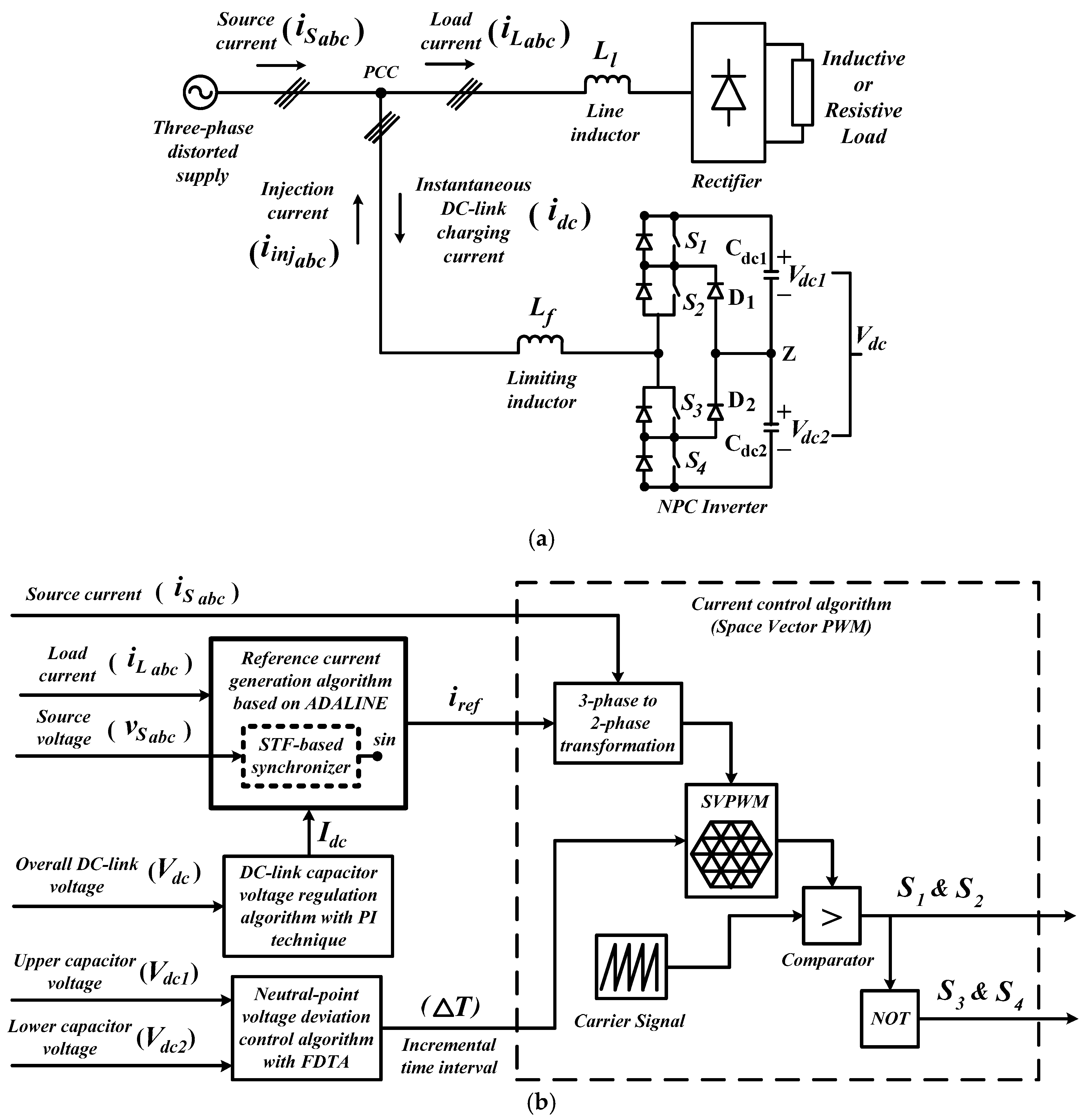
2. Working Principle and Control Algorithms of Shunt Active Power Filter (SAPF)
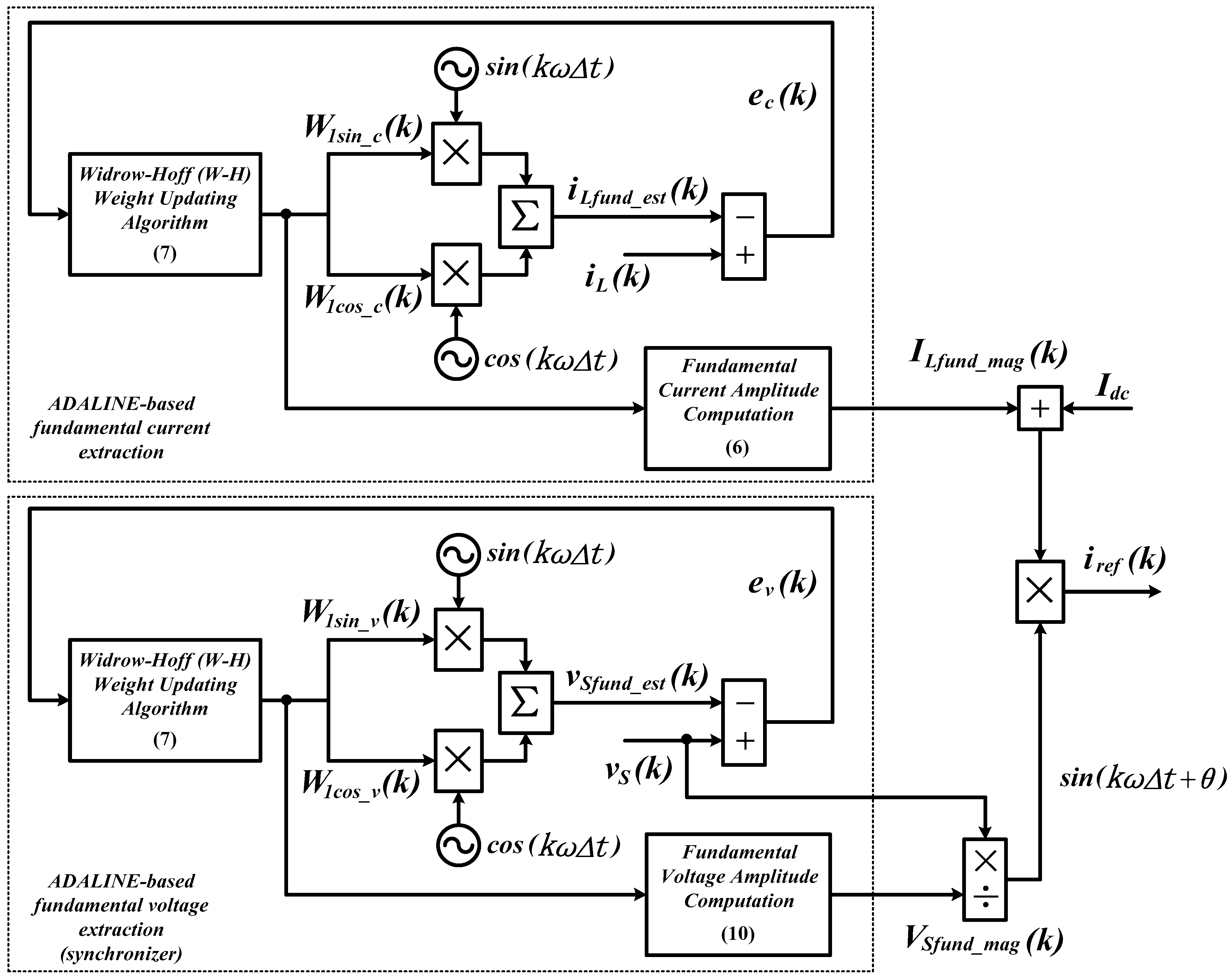
3. Self-Tuning Filter (STF)-Based Adaptive Linear Neuron (ADALINE) Algorithm
3.1. Unified ADALINE Algorithm
3.2. STF-Based Fundamental Voltage Extraction Algorithm (Synchronizer Algorithm)
- (1)
- Extract the fundamental (sinusoidal) source voltage from the measured source voltage ,
- (2)
- Compute the magnitude of fundamental source voltage , and
- (2)
- Divide directly with the computed magnitude .
4. Simulation Results
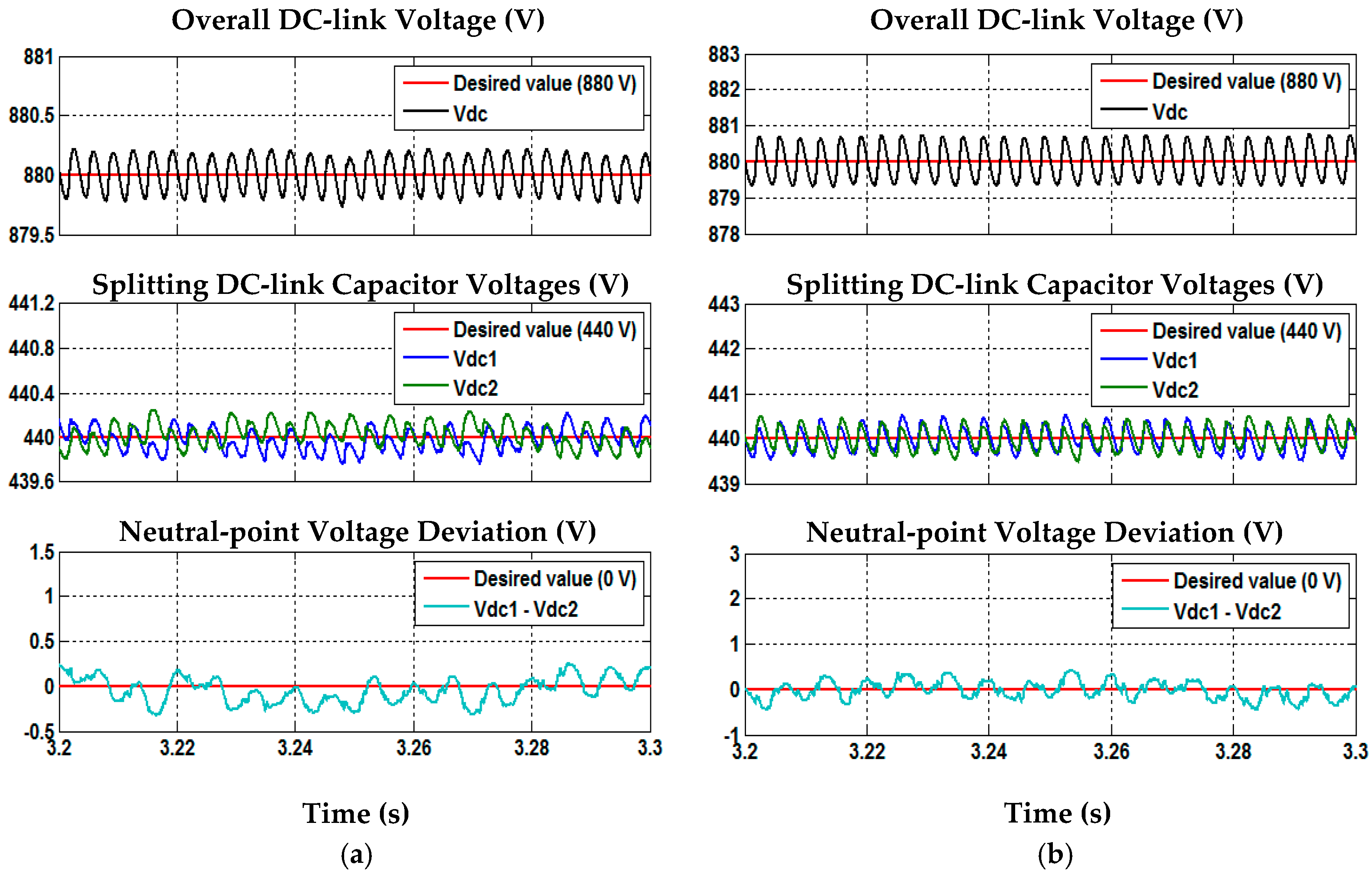
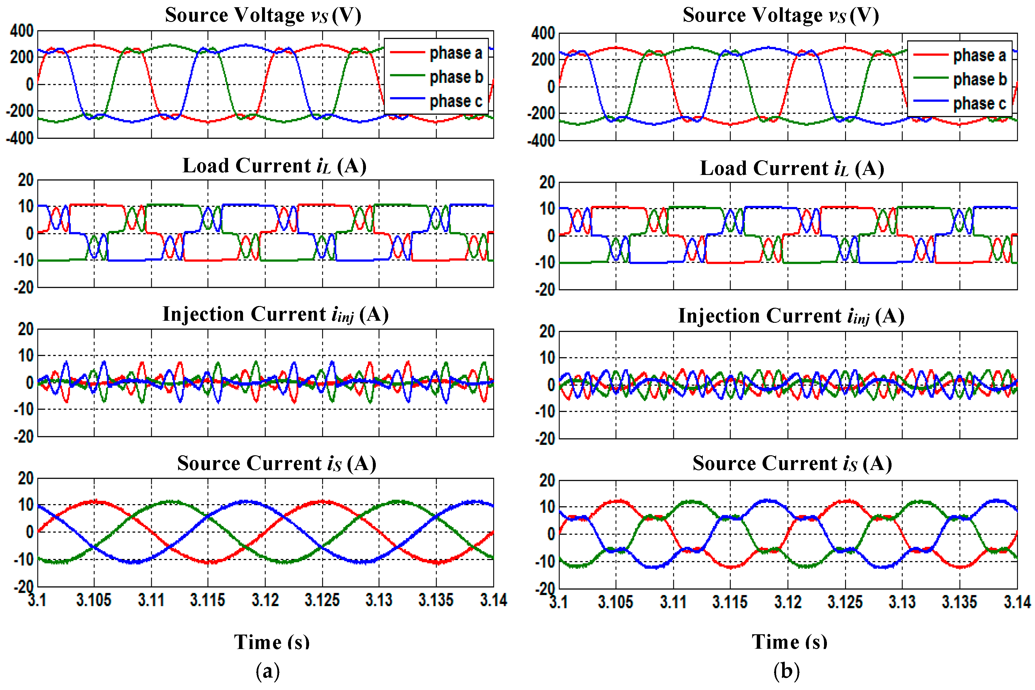
4.1. Balanced-Sinusoidal Source Voltage (Case 1)
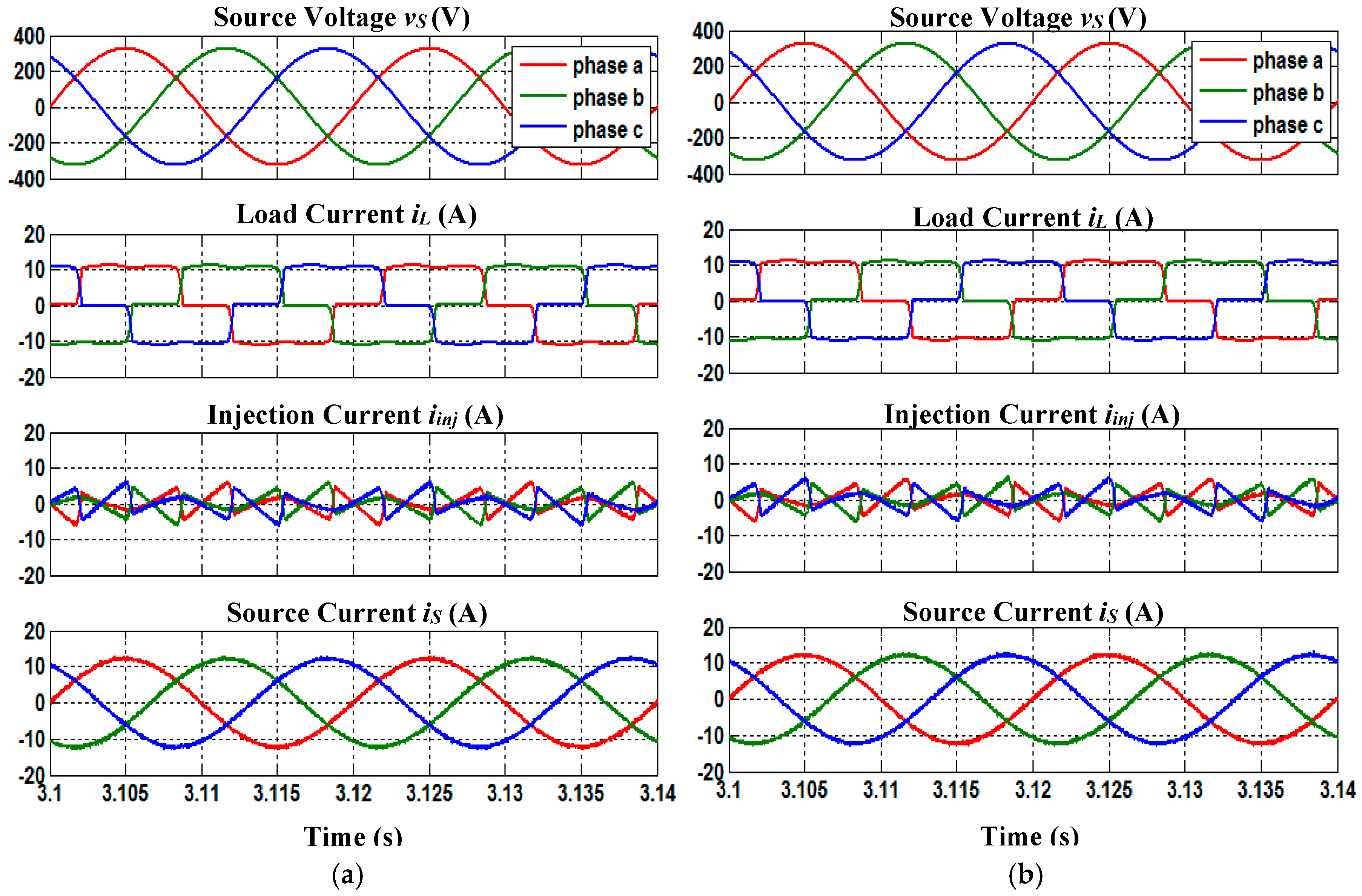
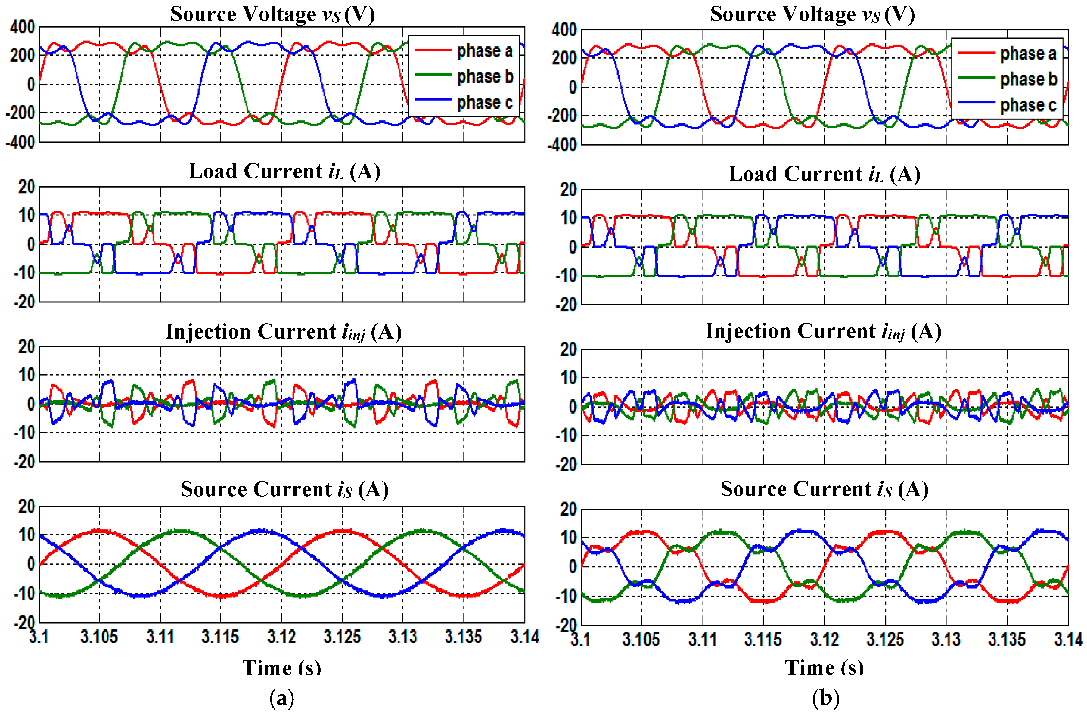
4.2. Balanced-Distorted Source Voltage Containing Only Odd-Order Harmonics (Case 2)
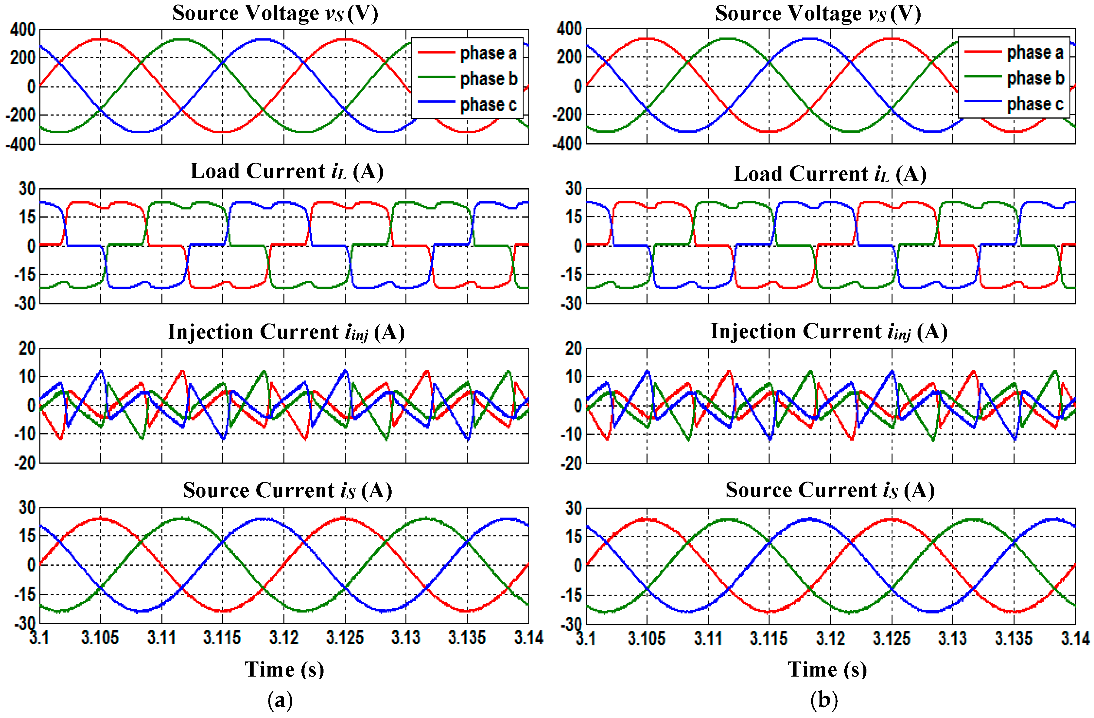
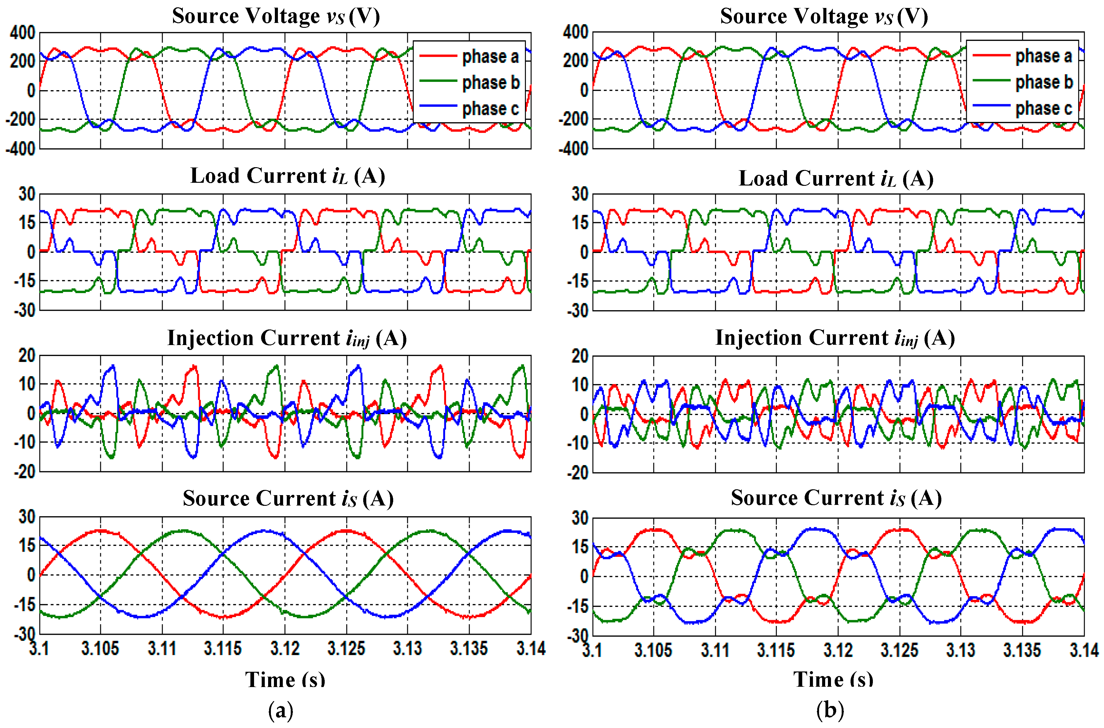
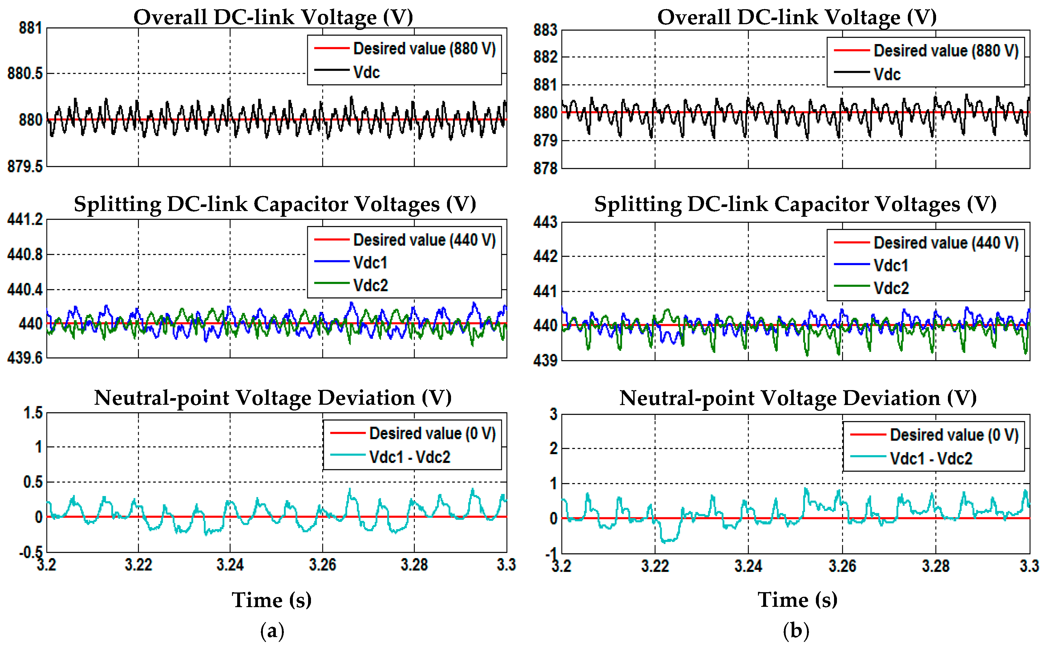
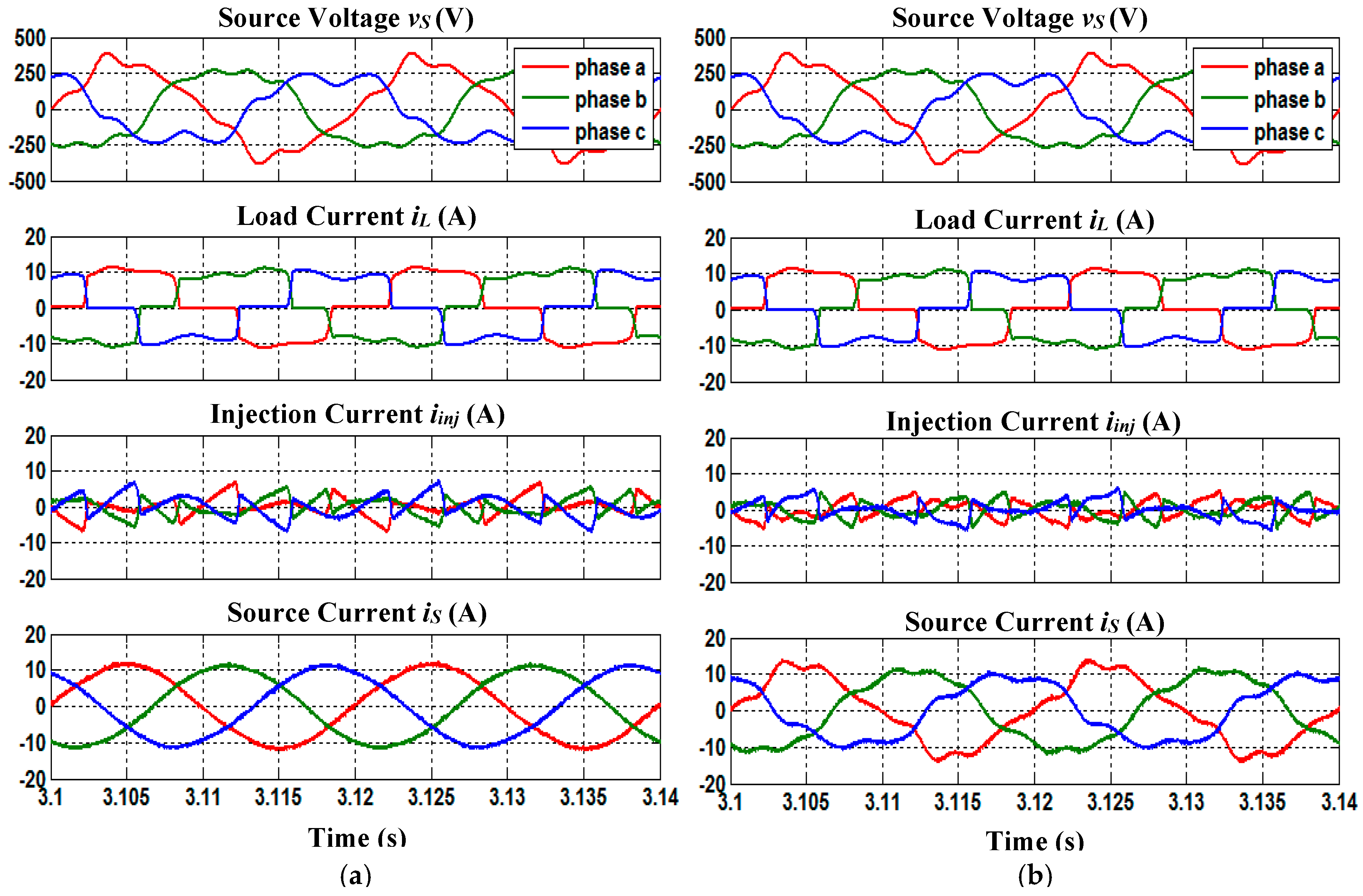
4.3. Balanced-Distorted Source Voltage Containing Both Odd-Order and Even-Order Harmonics (Case 3)
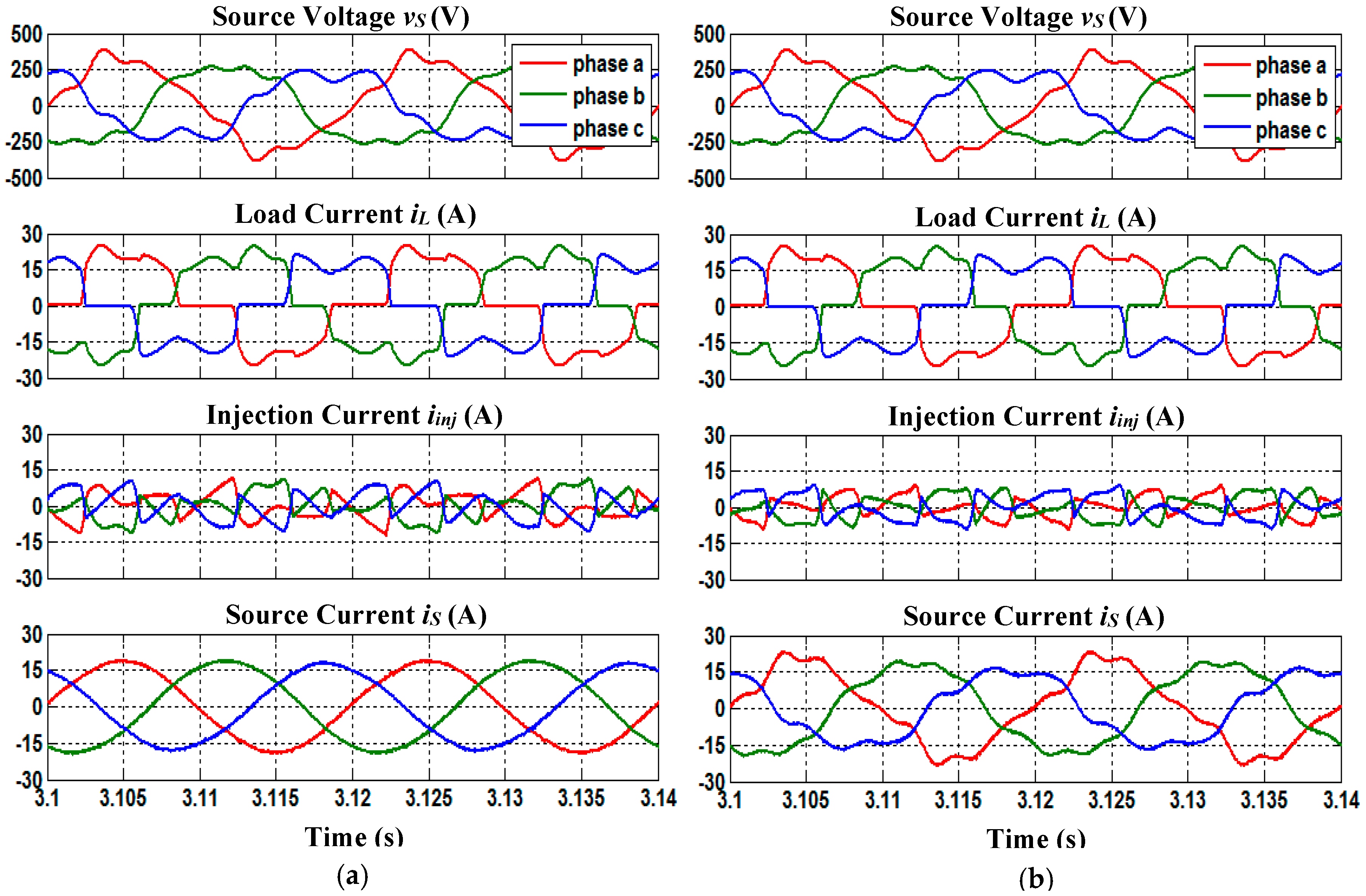
4.4. Unbalanced-Distorted Source Voltage (Case 4)
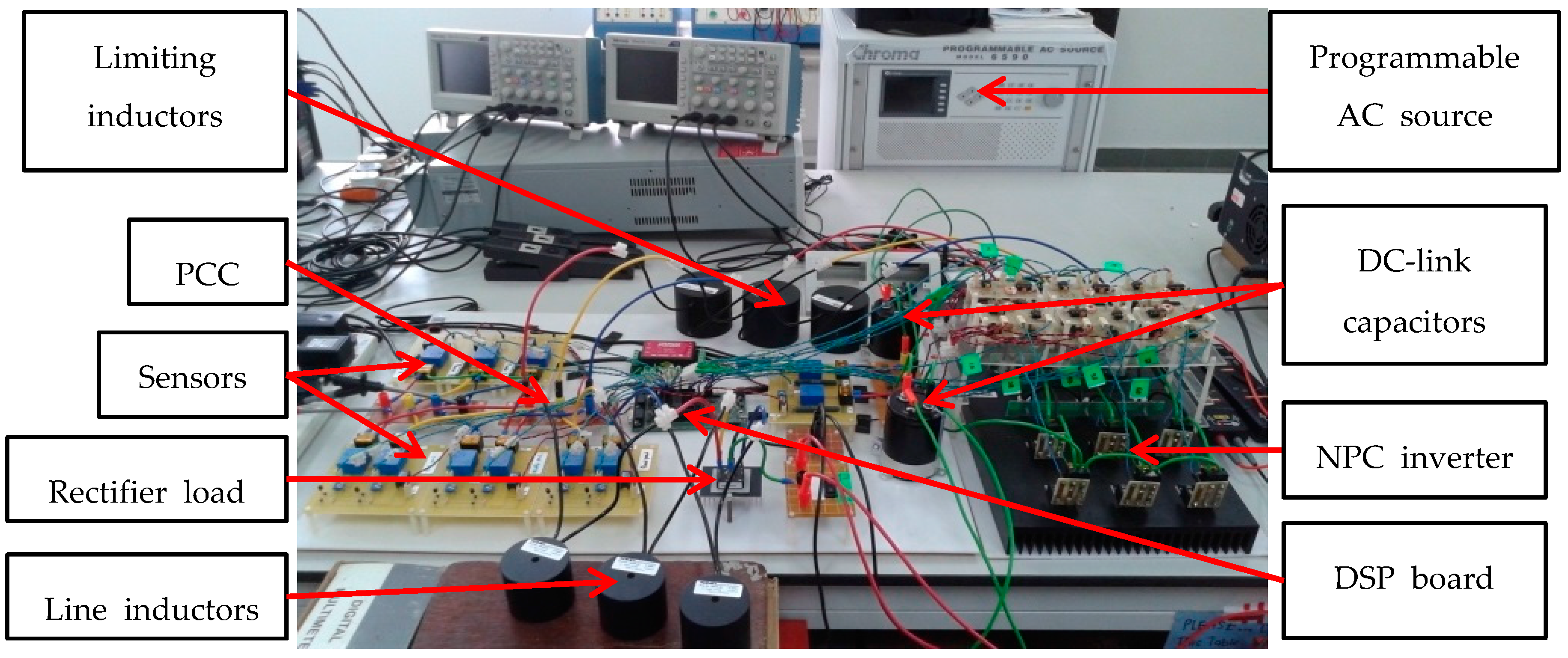
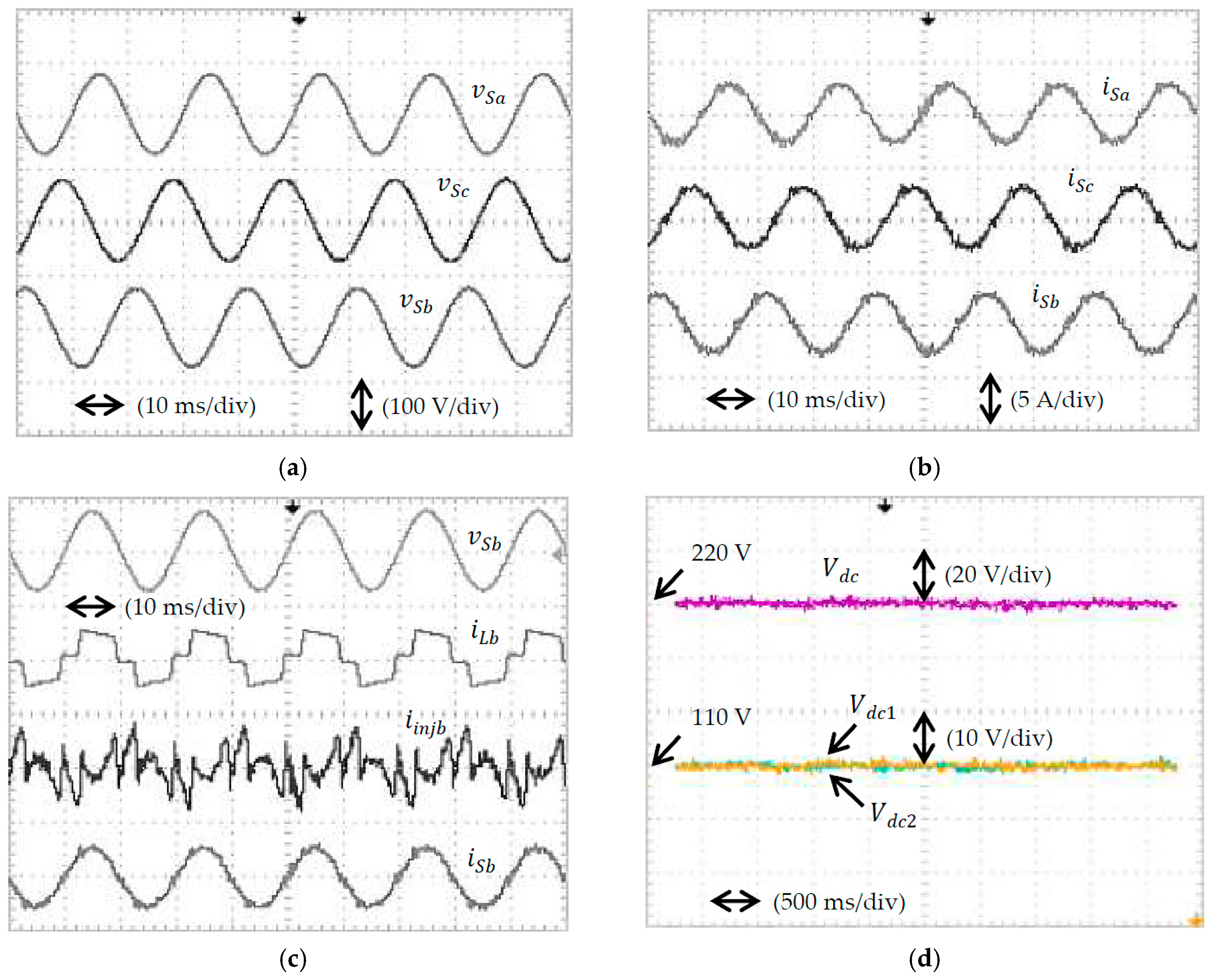
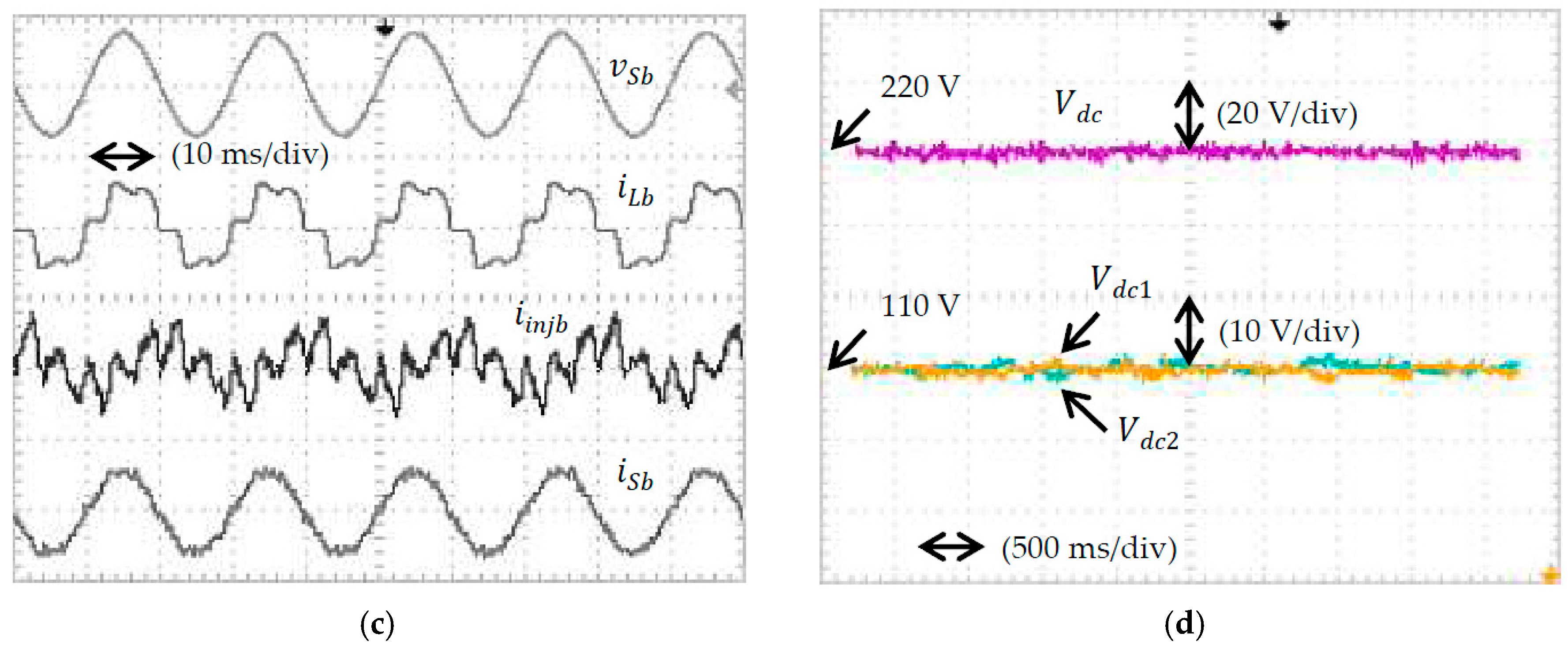
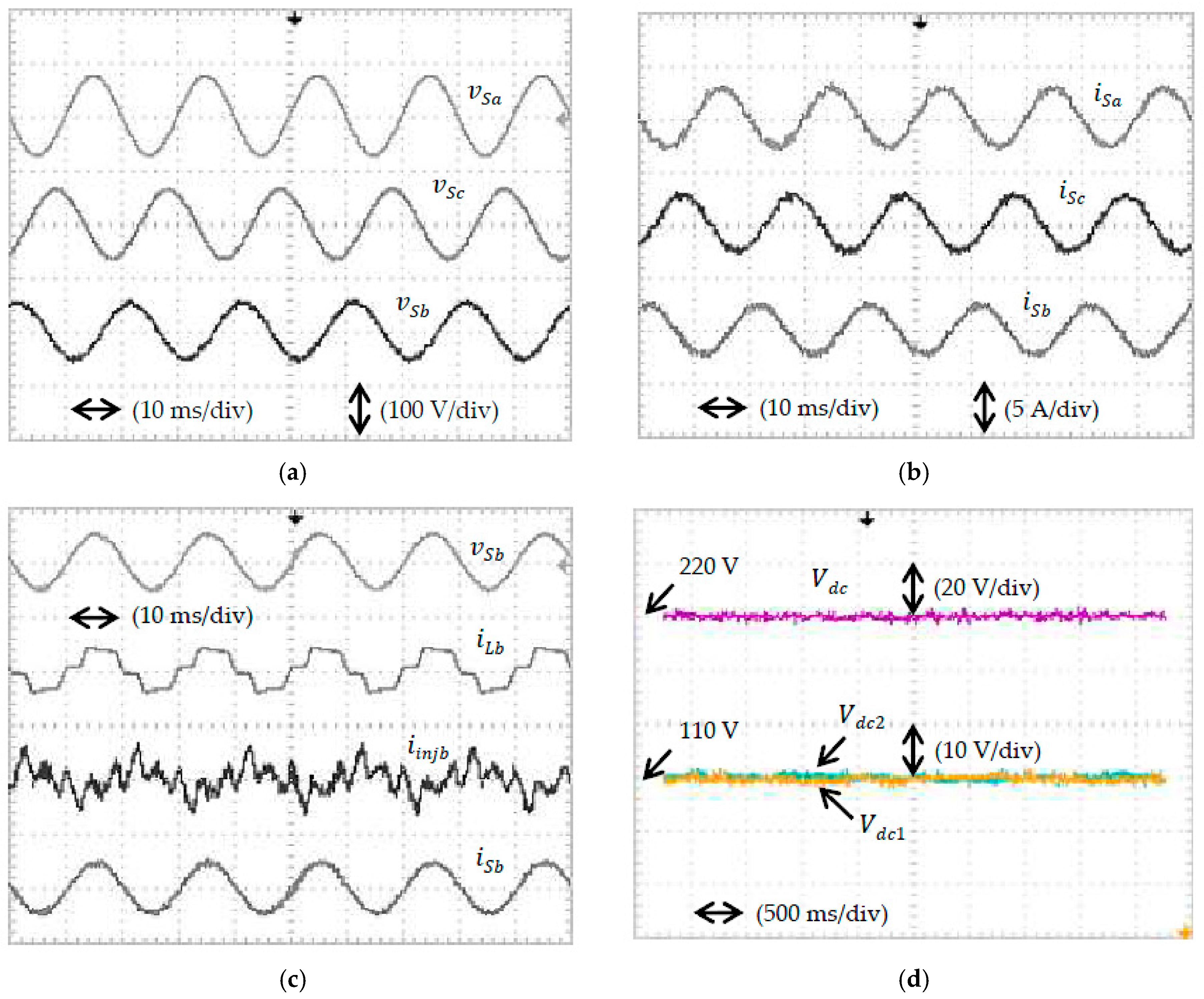
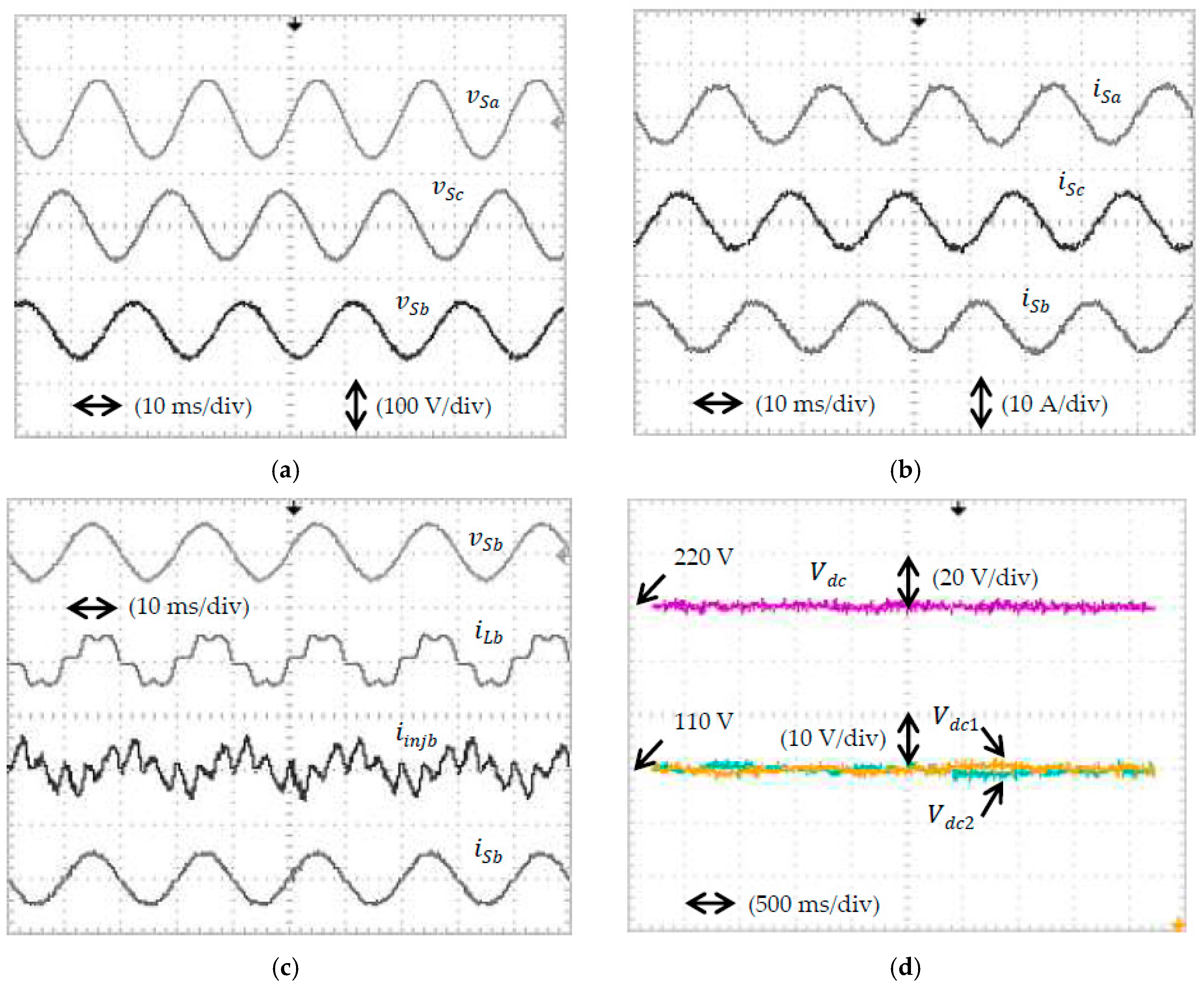
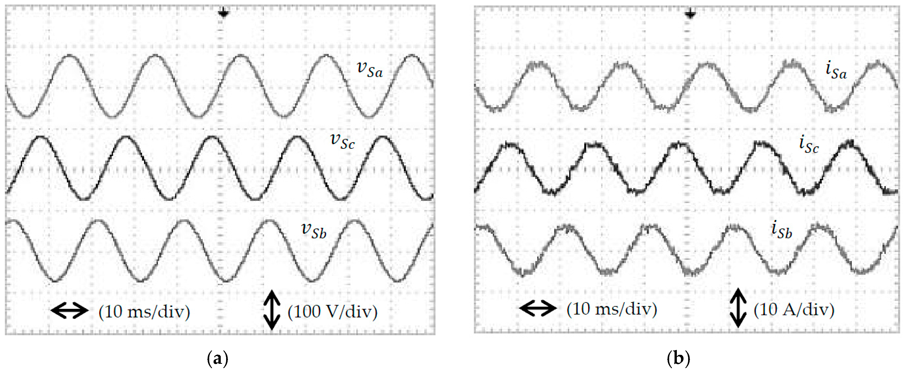
5. Experimental Verification
- Case A: balanced-sinusoidal source voltage, and
- Case B: unbalanced-sinusoidal source voltage.
6. Conclusions
Author Contributions
Conflicts of Interest
References
- Hoon, Y.; Radzi, M.A.M.; Hassan, M.K.; Mailah, N.F. Enhanced instantaneous power theory with average algorithm for indirect current controlled three-level inverter-based shunt active power filter under dynamic state conditions. Math. Probl. Eng. 2016, 2016, 9682512. [Google Scholar] [CrossRef]
- Hoon, Y.; Radzi, M.A.M.; Hassan, M.K.; Mailah, N.F. DC-link capacitor voltage regulation for three-phase three-level inverter-based shunt active power filter with inverted error deviation control. Energies 2016, 9, 533. [Google Scholar] [CrossRef]
- Akagi, H. Active harmonic filters. Proc. IEEE 2005, 93, 2128–2141. [Google Scholar] [CrossRef]
- El-Habrouk, M.; Darwish, M.K.; Mehta, P. Active power filters: A review. IEE Proc. Electr. Power Appl. 2000, 147, 403–413. [Google Scholar] [CrossRef]
- Djazia, K.; Krim, F.; Chaoui, A.; Sarra, M. Active power filtering using the zdpc method under unbalanced and distorted grid voltage conditions. Energies 2015, 8, 1584–1605. [Google Scholar] [CrossRef]
- Kale, M.; Ozdemir, E. Harmonic and reactive power compensation with shunt active power filter under non-ideal mains voltage. Electr. Power Syst. Res. 2005, 74, 363–370. [Google Scholar] [CrossRef]
- Jain, N.; Gupta, A. Comparison between two compensation current control methods of shunt active power filter. Int. J. Eng. Res. Gen. Sci. 2014, 2, 603–615. [Google Scholar]
- Wamane, S.S.; Baviskar, J.R.; Wagh, S.R. A comparative study on compensating current generation algorithms for shunt active filter under non-linear load conditions. Int. J. Sci. Res. Publ. 2013, 3, 1–6. [Google Scholar]
- Dey, P.; Mekhilef, S. Synchronous reference frame based control technique for shunt hybrid active power filter under non-ideal voltage. In Proceedings of the IEEE Innovative Smart Grid Technologies—Asia (ISGT Asia), Kuala Lumpur, Malaysia, 20–23 May 2014; pp. 481–486. [Google Scholar]
- Cao, W.; Liu, K.; Ji, Y.; Wang, Y.; Zhao, J. Design of a four-branch lcl-type grid-connecting interface for a three-phase, four-leg active power filter. Energies 2015, 8, 1606–1627. [Google Scholar] [CrossRef]
- Qasim, M.; Kanjiya, P.; Khadkikar, V. Artificial-neural-network-based phase-locking scheme for active power filters. IEEE Trans. Ind. Electron. 2014, 61, 3857–3866. [Google Scholar] [CrossRef]
- Chauhan, S.K.; Shah, M.C.; Tiwari, R.R.; Tekwani, P.N. Analysis, design and digital implementation of a shunt active power filter with different schemes of reference current generation. IET Power Electron. 2014, 7, 627–639. [Google Scholar] [CrossRef]
- Rodríguez, J.; Lai, J.-S.; Peng, F.Z. Multilevel inverters: A survey of topologies, controls and applications. IEEE Trans. Ind. Electron. 2002, 49, 724–738. [Google Scholar] [CrossRef]
- Soto, D.; Green, T.C. A comparison of high-power converter topologies for the implementation of facts controllers. IEEE Trans. Ind. Electron. 2002, 49, 1072–1080. [Google Scholar] [CrossRef]
- Gui, S.W.; Lin, Z.J.; Huang, S.H. A varied vsvm strategy for balancing the neutral-point voltage of dc-link capacitors in three-level NPC converters. Energies 2015, 8, 2032–2047. [Google Scholar] [CrossRef]
- Salim, C.; Toufik, B.M. Three-level (npc) shunt active power filter performances based on fuzzy controller for harmonic currents compensation under non-ideal voltage conditions. Int. J. Electr. Eng. Inform. 2014, 6, 342–358. [Google Scholar] [CrossRef]
- Hoon, Y.; Radzi, M.A.M.; Hassan, M.K.; Mailah, N.F.; Wahab, N.I.A. A simplified synchronous reference frame for indirect current controlled three-level inverter-based shunt active power filters. J. Power Electron. 2016, 16, 1964–1980. [Google Scholar] [CrossRef]
- Bhattacharya, A.; Chakraborty, C. A shunt active power filter with enhanced performance using ann-based predictive and adaptive controllers. IEEE Trans. Ind. Electron. 2011, 58, 421–428. [Google Scholar] [CrossRef]
- Eskandarian, N.; Beromi, Y.A.; Farhangi, S. Improvement of dynamic behavior of shunt active power filter using fuzzy instantaneous power theory. J. Power Electron. 2014, 14, 1303–1313. [Google Scholar] [CrossRef]
- Popescu, M.; Bitoleanu, A.; Suru, V. A dsp-based implementation of the p-q theory in active power filtering under nonideal voltage conditions. IEEE Trans. Ind. Inform. 2013, 9, 880–889. [Google Scholar] [CrossRef]
- Monfared, M.; Golestan, S.; Guerrero, J.M. A new synchronous reference frame-based method for single-phase shunt active power filters. J. Power Electron. 2013, 13, 692–700. [Google Scholar] [CrossRef]
- Kulkarni, A.; John, V. Design of synchronous reference frame phase-locked loop with the presence of dc offsets in the input voltage. IET Power Electron. 2015, 8, 2435–2443. [Google Scholar] [CrossRef]
- Vodyakho, O.; Mi, C.C. Three-level inverter-based shunt active power filter in three-phase three-wire and four-wire systems. IEEE Trans. Power Electron. 2009, 24, 1350–1363. [Google Scholar] [CrossRef]
- Bhuvaneswari, G.; Nair, M.G.; Reddy, S.K. Comparison of synchronous detection and i. Cos φ shunt active filtering algorithms. In Proceedings of the International Conference on Power Electronics, Drives and Energy Systems, New Delhi, India, 12–15 December 2006; pp. 1–5. [Google Scholar]
- Sujitjorn, S.; Areerak, K.-L.; Kulworawanichpong, T. The dq axis with fourier (dqf) method for harmonic identification. IEEE Trans. Power Deliv. 2007, 22, 737–739. [Google Scholar] [CrossRef]
- Forghani, M.; Afsharnia, S. Online wavelet transform-based control strategy for upqc control system. IEEE Trans. Power Deliv. 2007, 22, 481–491. [Google Scholar] [CrossRef]
- Radzi, M.A.M.; Rahim, N.A. Neural network and bandless hysteresis approach to control switched capacitor active power filter for reduction of harmonics. IEEE Trans. Ind. Electron. 2009, 56, 1477–1484. [Google Scholar] [CrossRef]
- Singh, B.; Verma, V.; Solanki, J. Neural network-based selective compensation of current quality problems in distribution system. IEEE Trans. Ind. Electron. 2007, 54, 53–60. [Google Scholar] [CrossRef]
- Hamad, M.S.; Gadoue, S.M.; Williams, B.W. Harmonic compensation of a six-pulse current source controlled converter using neural network-based shunt active power filter. IET Power Electron. 2012, 5, 747–754. [Google Scholar] [CrossRef]
- Rahman, N.F.A.; Radzi, M.A.M.; Soh, A.C.; Mariun, N.; Rahim, N.A. Dual function of unified adaptive linear neurons based fundamental component extraction algorithm for shunt active power filter operation. Int. Rev. Electr. Eng. 2015, 10, 544–552. [Google Scholar]
- Zainuri, M.A.A.M.; Radzi, M.A.M.; Soh, A.C.; Mariun, N.; Rahim, N.A.; Hajighorbani, S. Fundamental active current adaptive linear neural networks for photovoltaic shunt active power filters. Energies 2016, 9, 397. [Google Scholar] [CrossRef]
- Chang, G.W.; Chen, C.-I.; Teng, Y.-F. Radial-basis-function-based neural network for harmonic detection. IEEE Trans. Ind. Electron. 2010, 57, 2171–2179. [Google Scholar] [CrossRef]
- Saribulut, L.; Teke, A.; Tumay, M. Artificial neural network-based discrete-fuzzy logic controlled active power filter. IET Power Electron. 2014, 7, 1536–1546. [Google Scholar] [CrossRef]
- Tey, L.H.; So, P.L.; Chu, Y.C. Improvement of power quality using adaptive shunt active filter. IEEE Trans. Power Deliv. 2005, 20, 1558–1568. [Google Scholar] [CrossRef]
- Vazquez, J.R.; Salmeron, P. Active power filter control using neural network technologies. IEE Proc. Electr. Power Appl. 2003, 150, 139–145. [Google Scholar] [CrossRef]
- Chang, G.W.; Yeh, C.M. Optimisation-based strategy for shunt active power filter control under non-ideal supply voltages. IEE Proc. Electr. Power Appl. 2005, 152, 182–190. [Google Scholar] [CrossRef]
- Chang, G.W.; Yeh, C.-M.; Chen, W.-C. Meeting IEEE-519 current harmonics and power factor constraints with a three-phase three-wire active power filter under distorted source voltages. IEEE Trans. Power Deliv. 2006, 21, 1648–1654. [Google Scholar] [CrossRef]
- Dinh, N.D.; Tuyen, N.D.; Fujita, G.; Funabashi, T. Adaptive notch filter solution under unbalanced and/or distorted point of common coupling voltage for three-phase four-wire shunt active power filter with sinusoidal utility current strategy. IET Gener. Transm. Distrib. 2015, 9, 1580–1596. [Google Scholar] [CrossRef]
- Abdulsalam, M.; Poure, P.; Karimi, S.; Saadate, S. New digital reference current generation for shunt active power filter under distorted voltage conditions. Electr. Power Syst. Res. 2009, 79, 759–765. [Google Scholar] [CrossRef]
- Hoon, Y.; Radzi, M.A.M.; Hassan, M.K.; Mailah, N.F. A refined self-tuning filter-based instantaneous power theory algorithm for indirect current controlled three-level inverter-based shunt active power filters under non-sinusoidal source voltage conditions. Energies 2017, 10, 277. [Google Scholar] [CrossRef]
- Biricik, S.; Redif, S.; Özerdem, Ö.C.; Khadem, S.K.; Basu, M. Real-time control of shunt active power filter under distorted grid voltage and unbalanced load condition using self-tuning filter. IET Power Electron. 2014, 7, 1895–1905. [Google Scholar] [CrossRef]
- Campanhol, L.B.G.; Silva, S.A.O.; Goedtel, A. Application of shunt active power filter for harmonic reduction and reactive power compensation in three-phase four-wire systems. IET Power Electron. 2014, 7, 2825–2836. [Google Scholar] [CrossRef]
- Hoon, Y.; Radzi, M.A.M.; Hassan, M.K.; Mailah, N.F. Neutral-point voltage deviation control for three-level inverter-based shunt active power filter with fuzzy-based dwell time allocation. IET Power Electron. 2016, 10, 429–441. [Google Scholar] [CrossRef]
- Dey, P.; Mekhilef, S. Current harmonics compensation with three-phase four-wire shunt hybrid active power filter based on modified d-q theory. IET Power Electron. 2015, 8, 2265–2280. [Google Scholar] [CrossRef]
- Massoud, A.M.; Finney, S.J.; Cruden, A.J.; Williams, B.W. Three-phase, three-wire, five-level cascaded shunt active filter for power conditioning, using two different space vector modulation techniques. IEEE Trans. Ind. Electron. 2007, 22, 2349–2361. [Google Scholar] [CrossRef]
- Gupta, A.K.; Khambadkone, A.M. A space vector pwm scheme for multilevel inverters based on two-level space vector pwm. IEEE Trans. Ind. Electron. 2006, 53, 1631–1639. [Google Scholar] [CrossRef]
- Hu, H.; Yao, W.; Lu, Z. Design and implementation of three-level space vector pwm ip core for fpgas. IEEE Trans. Ind. Electron. 2007, 22, 2234–2244. [Google Scholar] [CrossRef]
- IEEE Power and Energy Society. IEEE Standard 519, IEEE Recommended Practice and Requirement for Harmonic Control in Electric Power Systems; Institute of Electrical and Electronics Engineers, Inc.: New York, NY, USA, 2014. [Google Scholar]
- Round, S.D.; Duke, R.M. Real-time optimization of an active filter’s performance. IEEE Trans. Ind. Electron. 1994, 41, 278–284. [Google Scholar] [CrossRef]


| Parameter | Value | Unit |
|---|---|---|
| Fundamental source voltage (line to line) | 400 (rms) | V |
| Fundamental frequency | 50 | Hz |
| DC-link capacitor | 3300 (each) | μF |
| Overall DC-link reference voltage | 880 | V |
| Limiting inductor | 5 | mH |
| Switching frequency | 25 | kHz |
| Reference Current Generation Algorithm | Total Harmonic Distortion, THD (%) | |||||
|---|---|---|---|---|---|---|
| Phase a | Phase b | Phase c | ||||
| Inductive | Resistive | Inductive | Resistive | Inductive | Resistive | |
| Before Connecting SAPF | ||||||
| N/A | 27.34 | 27.01 | 27.34 | 27.01 | 27.34 | 27.01 |
| After Connecting SAPF | ||||||
| STF-based ADALINE | 2.60 | 1.29 | 2.57 | 1.28 | 2.57 | 1.31 |
| Unified ADALINE | 3.28 | 1.38 | 3.34 | 1.39 | 3.26 | 1.42 |
| Reference Current Generation Algorithm | Total Harmonic Distortion, THD (%) | |||||
|---|---|---|---|---|---|---|
| Phase a | Phase b | Phase c | ||||
| Inductive | Resistive | Inductive | Resistive | Inductive | Resistive | |
| Before Connecting SAPF | ||||||
| N/A | 33.54 | 25.56 | 33.54 | 25.56 | 33.54 | 25.56 |
| After Connecting SAPF | ||||||
| STF-based ADALINE | 3.19 | 2.00 | 3.19 | 1.96 | 3.21 | 1.97 |
| Unified ADALINE | 21.12 | 20.71 | 21.73 | 21.18 | 20.89 | 20.48 |
| Reference Current Generation Algorithm | Total Harmonic Distortion, THD (%) | |||||
|---|---|---|---|---|---|---|
| Phase a | Phase b | Phase c | ||||
| Inductive | Resistive | Inductive | Resistive | Inductive | Resistive | |
| Before Connecting SAPF | ||||||
| N/A | 39.86 | 37.70 | 39.86 | 37.70 | 39.86 | 37.70 |
| After Connecting SAPF | ||||||
| STF-based ADALINE | 3.95 | 3.10 | 3.89 | 3.13 | 3.94 | 3.06 |
| Unified ADALINE | 22.59 | 22.36 | 23.01 | 22.86 | 22.27 | 22.05 |
| Reference Current Generation Algorithm | Total Harmonic Distortion, THD (%) | |||||
|---|---|---|---|---|---|---|
| Phase a | Phase b | Phase c | ||||
| Inductive | Resistive | Inductive | Resistive | Inductive | Resistive | |
| Before Connecting SAPF | ||||||
| N/A | 31.95 | 34.04 | 26.57 | 23.98 | 34.16 | 35.53 |
| After Connecting SAPF | ||||||
| STF-based ADALINE | 3.31 | 2.86 | 2.60 | 1.87 | 2.74 | 2.27 |
| Unified ADALINE | 17.82 | 17.49 | 11.49 | 11.31 | 16.99 | 16.55 |
| Cases of Source Voltage Conditions | Total Harmonic Distortion, THD (%) | |||||
|---|---|---|---|---|---|---|
| Phase a | Phase b | Phase c | ||||
| Inductive | Resistive | Inductive | Resistive | Inductive | Resistive | |
| Before Connecting SAPF | ||||||
| Case A | 26.10 | 24.83 | 25.88 | 24.85 | 26.27 | 25.06 |
| Case B | 22.73 | 21.65 | 27.32 | 26.33 | 23.40 | 22.18 |
| After Connecting SAPF | ||||||
| Case A | 3.48 | 3.21 | 3.65 | 3.31 | 3.54 | 3.25 |
| Case B | 3.52 | 3.35 | 4.15 | 3.91 | 3.84 | 3.66 |
© 2017 by the authors. Licensee MDPI, Basel, Switzerland. This article is an open access article distributed under the terms and conditions of the Creative Commons Attribution (CC BY) license (http://creativecommons.org/licenses/by/4.0/).
Share and Cite
Hoon, Y.; Mohd Radzi, M.A.; Hassan, M.K.; Mailah, N.F. A Self-Tuning Filter-Based Adaptive Linear Neuron Approach for Operation of Three-Level Inverter-Based Shunt Active Power Filters under Non-Ideal Source Voltage Conditions. Energies 2017, 10, 667. https://doi.org/10.3390/en10050667
Hoon Y, Mohd Radzi MA, Hassan MK, Mailah NF. A Self-Tuning Filter-Based Adaptive Linear Neuron Approach for Operation of Three-Level Inverter-Based Shunt Active Power Filters under Non-Ideal Source Voltage Conditions. Energies. 2017; 10(5):667. https://doi.org/10.3390/en10050667
Chicago/Turabian StyleHoon, Yap, Mohd Amran Mohd Radzi, Mohd Khair Hassan, and Nashiren Farzilah Mailah. 2017. "A Self-Tuning Filter-Based Adaptive Linear Neuron Approach for Operation of Three-Level Inverter-Based Shunt Active Power Filters under Non-Ideal Source Voltage Conditions" Energies 10, no. 5: 667. https://doi.org/10.3390/en10050667
APA StyleHoon, Y., Mohd Radzi, M. A., Hassan, M. K., & Mailah, N. F. (2017). A Self-Tuning Filter-Based Adaptive Linear Neuron Approach for Operation of Three-Level Inverter-Based Shunt Active Power Filters under Non-Ideal Source Voltage Conditions. Energies, 10(5), 667. https://doi.org/10.3390/en10050667