1. Introduction
In the active distribution grids, large quantities of Intelligent Electronic Devices (IEDs) are put into operation to enhance the system reliability and flexibility. These IEDs are widely deployed with the pole top switchgears, secondary substations, ring main units, and the management units of Distributed Energy Resources (DER). They can share the measuring data and interact with each other to execute distributed intelligence for various applications. Some examples are Fault Location, Isolation, and Service Restoration (FLISR) [
1,
2,
3] schemes based on distributed or multi-agent control, the decentralized distribution network reconfiguration [
4], and the Direct Transfer Trip (DTT) for anti-islanding protection [
5,
6]. Realized with distributed IEDs, these schemes operate independently from the master station and have faster responses to abnormal or faulty conditions of the distribution network. Therefore, they are more and more favored by the electric utilities owing to the improvement of power supply reliability. In contrast, the traditional centralized architecture is becoming less popular because it uses one single decision-making component to process all the data and cannot adapt well to the dynamic topology changes in distribution grids [
7].
On the other hand, traditional communication protocols in the Distribution Automation System (DAS) such as International Electrotechnical Commission (IEC) 60870-5-101/104 and Distributed Network Protocol (DNP) 3.0 usually define the format of messages and simple descriptions about the data types for “tele-metering”, “tele-control”, and “tele-indication”. The IED manufacturers and DAS operators have to check the primary network diagram and the data sheet to bind the communication data to the physical objects, which is an error-prone process resulting in a huge workload during system integration [
8]. It is obvious that traditional protocols are difficult to coordinate with IEDs from multiple vendors to implement the distributed applications. Fortunately, the novel IEC 61850 provides the standardized communication architecture to facilitate interoperability between IEDs and has become one of the most important protocols for power utility automation. It has built a series of standards for the Substation Automation System (SAS) and smart grids. It presents the object-oriented data models, the consistent Abstract Communication Service Interfaces (ACSI), and the System Configuration Language (SCL)-based configuration files with good self-description capabilities [
9,
10,
11,
12,
13]. It allows exchanging data and supporting interoperability between diverse devices in a client/server or peer-to-peer mode [
14]. Researchers have made significant efforts to analyze, evaluate, and improve the communication performance when using IEC 61850 within a substation and between substations [
15,
16,
17,
18]. These advantages promote the interoperability between IEDs and make IEC 61850 comparatively suitable for the distributed intelligent applications in DAS.
For now, the IEC 57th Technical Committee, 17th Working Group (IEC TC57 WG17) has begun drafting the 90-6 technical report to guide the IEC 61850 applications to DAS, which pays much attention to the use case collections, new Logical Node (LN) classes, and IED configuration issues. Some researchers have already presented the IEC 61850-based applications to DAS. For example, in [
19], G. Zhabelova and V. Vyatkin proposed a multi-agent smart grid automation architecture based on the combination of IEC 61850 object-based modeling and interoperable communication with IEC 61499 function blocks of executable specification. G. Han et al. [
20] proposed the information model of Feeder Terminal Units (FTU) in DAS using the IEC 61850 method, wherein the information models and communication services are mapped into the tele-control protocol of IEC 60870-5-104. In [
21], a fast FLISR algorithm was proposed using IEC 61850 based Generic Object Oriented Substation Event (GOOSE) technology. In [
22], the Logical Nodes (LNs) were added for distribution feeder fault detection, and a new mapping method was proposed using Web Services for information model exchange and IEC 60870-5-104 for transmitting real-time data. In [
23], an IEC 61850 model expansion towards a distributed FLISR system was put forward based on the requirement analysis of a variety of distributed FLISR modes. In addition to the data models and service mappings, the SCL configuration is also of great importance to IEC 61850 implementations. For instance, L. Zhu, et al. [
24] proposed the configuration description of a communication network in SAS via extending the SCL communication model in IEC 61850-6. I.J. Shin et al. [
25] proposed the configuration method of placing the IEC 61850 information model onto an open-platform communication unified architecture using SCL files.
Nevertheless, the research about IEC 61850’s configuration for DAS is deficient. In [
9], the SCL files and configuration method were designed for the SAS but were not appropriate for DAS. In [
22], a discovery/register method was proposed to improve “plug and play” capability of IEDs in the DAS by getting their IEC 61850-based information models. Similarly, W. Deng, et al. [
26] proposed the micro-grid “plug and play” function using the established IEC 61850 information models of micro-grid IEDs. These “plug and play” functions just inquire the configuration versions but neglect to detect the probable mal-operations on configuration files. In [
27], it modeled the source data as structured object references to describe the data flow of tele-protection between LNs on different substation IEDs, where the primary topology and IED connections were fixed. Similar concepts can be used for supporting the distributed applications in DAS. However, the dynamic topology of Medium Voltage (MV) distribution networks changes more frequently; thus the data flow configuration must be modified correspondingly.
At present, there is no discussion about the IEC 61850 configuration solution to DAS, let alone the consideration of dynamic topology and data flow changes for distributed intelligence. This article proposes the configuration solution to IEC 61850 implementations in DAS especially for the distributed applications. It uses the new SCL models to describe the topology of the distribution network and presents a new CID (Configured IED Description) file to include the topology, communication system, and the functional parameters and data models, as required by distributed applications. The IED’s automatic identification method is put forward to check the configuration status automatically and contribute to the remote configuration. By means of the proposed solution, IEDs in DAS can process the dynamic topology and re-establish the data flows between peer IEDs without depending on the master station; thus the distributed applications are executed more autonomously and efficiently.
2. Configuration Requirements of the DAS
The structure and function of DAS are distinguished from the SAS, and there are special requirements of the configuration. With the IEC 61850 SCL scheme, the configuration of a multiple IEDs implemented system is done together and considered a configuration project.
2.1. System Boundary of a Configuration Project
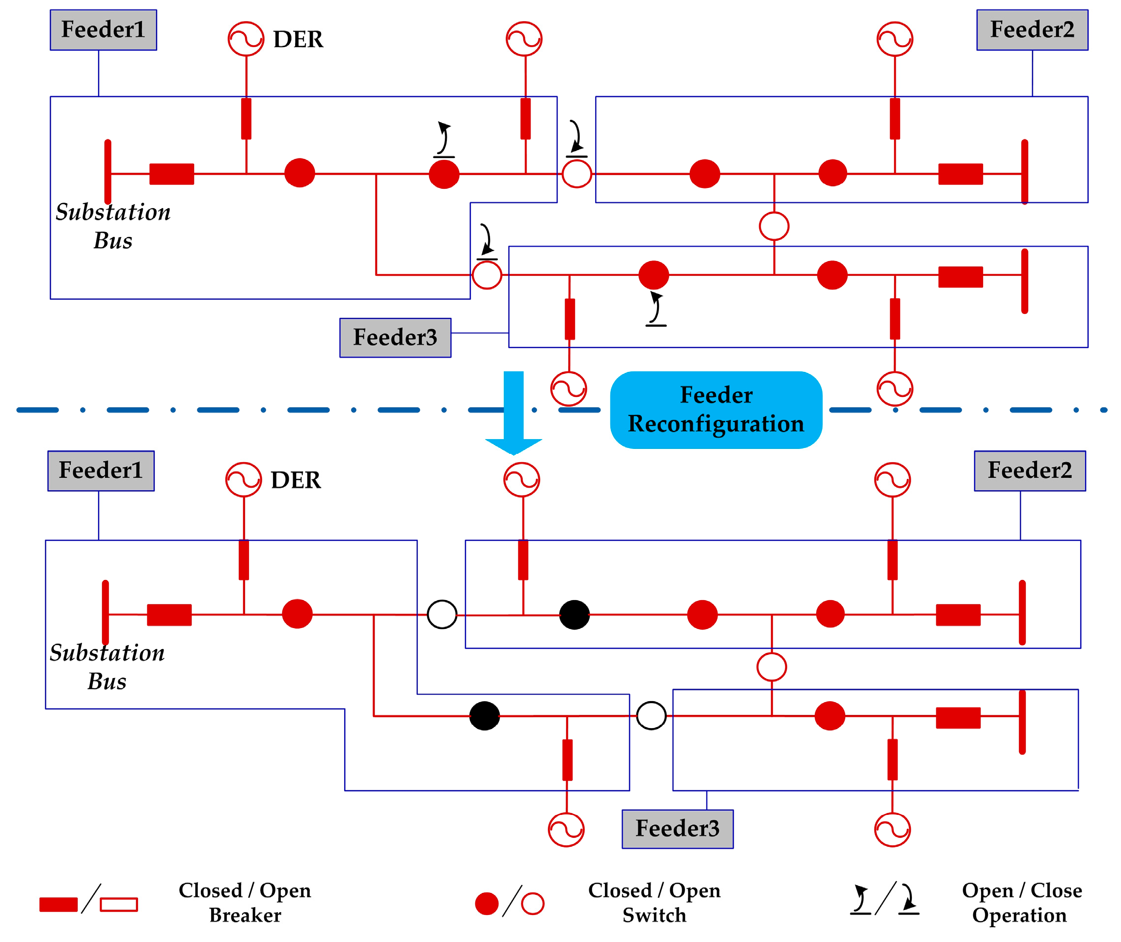
In the SAS, the system boundary of a configuration project is a primary substation. On the other hand, IEDs in DAS spread widely along MV feeders and are located at a variety of pole-mounted cabinets, Ring Main Units (RMU), secondary substations, etc. There is no distinct system boundary of a configuration project. It is necessary to divide the distribution network into independent subareas for respective configuration projects.
In most cases, the MV network is designed in a closed loop but operates in an open loop. Several feeders are interconnected via the normally open switches/breakers. The normally open switches will be closed and other ones become opened due to the fault processing, service restoration, or optimal network reconfiguration. Thus, the topological region of a MV feeder changes dynamically, but the Interconnected Feeders’ Group (IFG) is basically fixed. As shown in
Figure 1, Feeder1–Feeder3 vary with the switching operations, but the IFG of these three feeders stays the same. From the point of DAS’s perspective, IEDs in an IFG have more interactions, but those belonging to different IFGs seldom need to exchange information.
Therefore, we select the IFG as the system boundary of a configuration project for the DAS. IEDs’ configuration within an IFG should take into consideration their interrelationships and be managed as a whole.
2.2. Topology Configuration for Distributed Applications
IEDs hosting the decentralized functions must be aware of the primary topology based relationships. As depicted in [
23], the distributed fault location unit in an IED requests the short-circuit fault detection results from its adjacent IEDs; the fault isolation unit will inform its neighbor IEDs to trip the adjacent switches if the local switch fails to operate. In [
5], the DTT-based anti-islanding function must detect the real-time topology of an IFG to recognize which DER plants are now connected to this feeder. This allows the DTT signals to be sent to the right IEDs to disconnect DERs from the feeder as soon as the main circuit breaker has been tripped due to a fault.
In principle, the topology based information can be processed by the master station and then transferred to the feeder IEDs, but this is not the most efficient way to perform topology processing for distributed applications. The better way is to configure the static topology onto IEDs and allow them to process the dynamic topology autonomously [
28]. In this paper, IEDs in the DAS are classified into three types according to the embedded distributed applications.
Type B: The IED supports the basic Distribution Supervisory Control and Data Acquisition (DSCADA), which is just a server or controlled station to the master station and other client IEDs. Thus, it needs no topology configuration.
Type D1: In addition to the DSCADA function, the IED also knows its immediate neighbors within the distribution network to realize the decentralized DA functions. It is not only a server or controlled station but is also a client or controlling station to the adjacent IEDs.
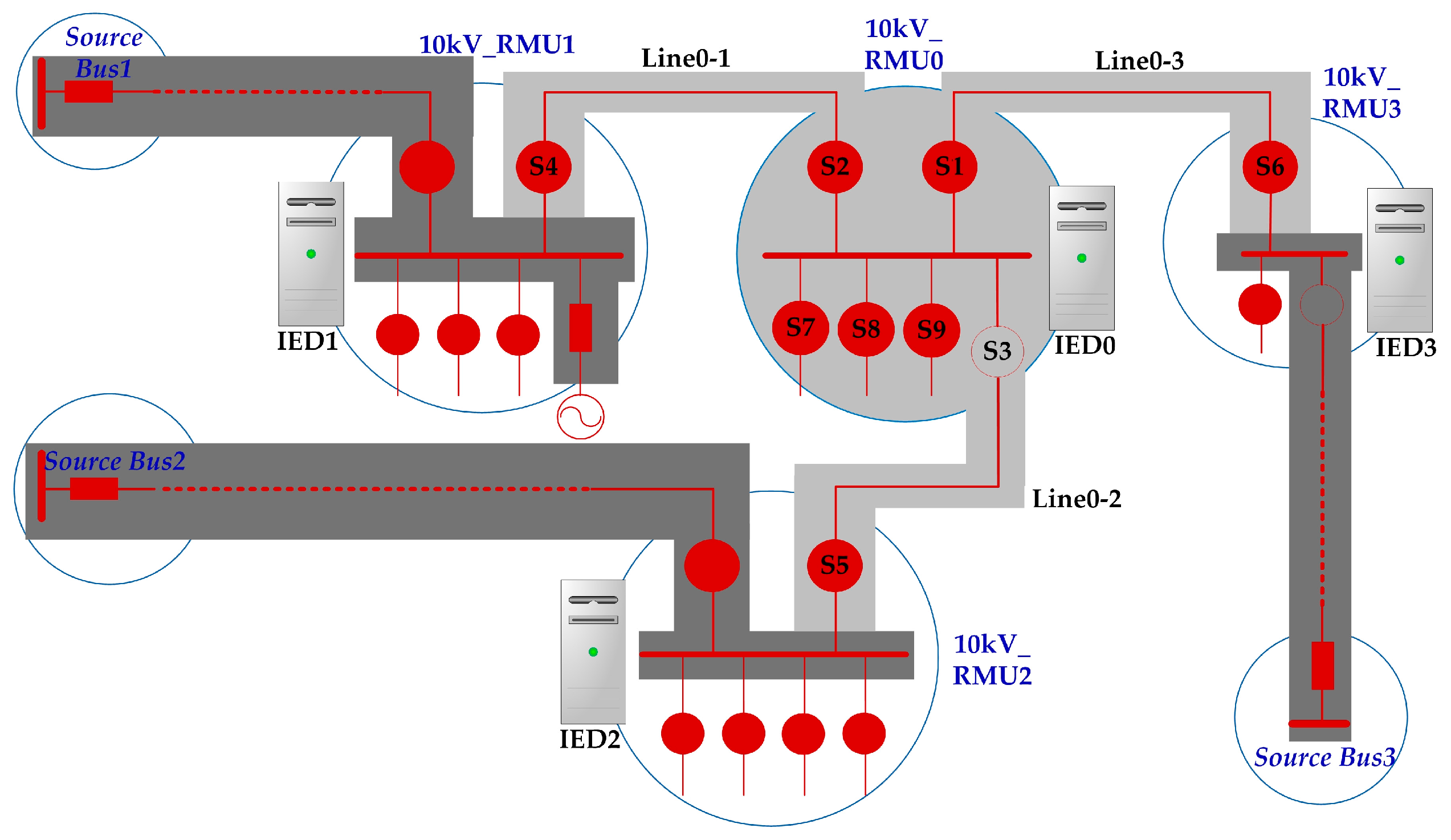
For example, the distributed fault location and isolation unit needs to know its immediate neighbors. In
Figure 2, the neighborhood topology of IED0 is colored in light gray, including the devices S1 to S9, Line0-1 to Line0-3, and the busbar in 10 kV_RMU0.
Type D2: In addition to the DSCADA function and the communication with its immediate neighbors, the IED also communicates with remote IEDs to achieve the distributed applications. It is not only a server or controlled station but is also a client or controlling station to remote IEDs, which are beyond its neighborhood topology but within the IFG.
For example, the DTT based anti-islanding function and the decentralized service restoration function need to be configured with the static topology of the whole IFG. The IFG topology of an IED includes the internal area of this IED and the external feeder trunk of the IFG. It also contains the grid-on/off breakers of DER plants. In
Figure 2, the IFG topology of IED0 consists of both the light gray and the dark gray portions. The Type
D2 IED can obtain all the switches’ statues along the feeder trunk and determine the dynamic topology. Then it builds the data flow in real-time and performs the distributed functions autonomously.
2.3. Automatic Identification of IEDs for Remote Configuration
An SAS is deployed in the primary substation with a fixed topology, and the IEDs are configured at a local workstation before being installed. Follow-up additions, substitutions, or removals of IEDs are quite rare, but, in DAS, the IEDs are deployed widely along the distribution feeders. It is preferable to set up a remote configuration workstation to release the system engineer from travelling to the remote sites. What is more, the subsequent changes regarding IEDs are relatively common and their configurations need to be updated more frequently. It is difficult for the system engineer to manage the IEDs’ configuration versions and status manually. Therefore, it is significant for the remote workstation to check the IED’s configuration version and status automatically. Then it will carry out the corresponding configuration process. This paper proposes the automatic identification method through which an IED can register its configuration version and status information to the remote workstation so as to be recognized, checked, and configured.
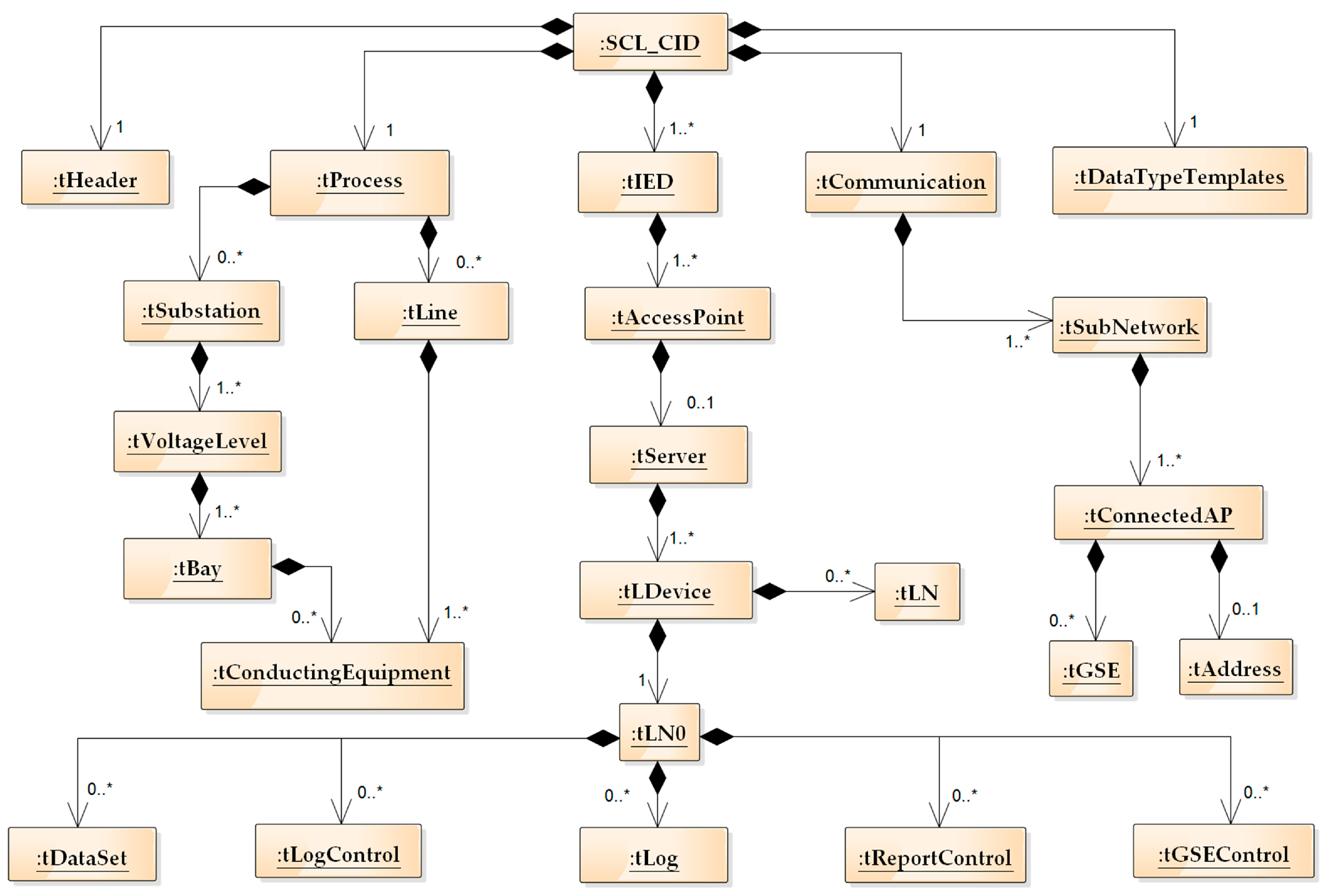
3. New SCL Model and Configuration Contents
3.1. SCL Extensions to Distribution Network
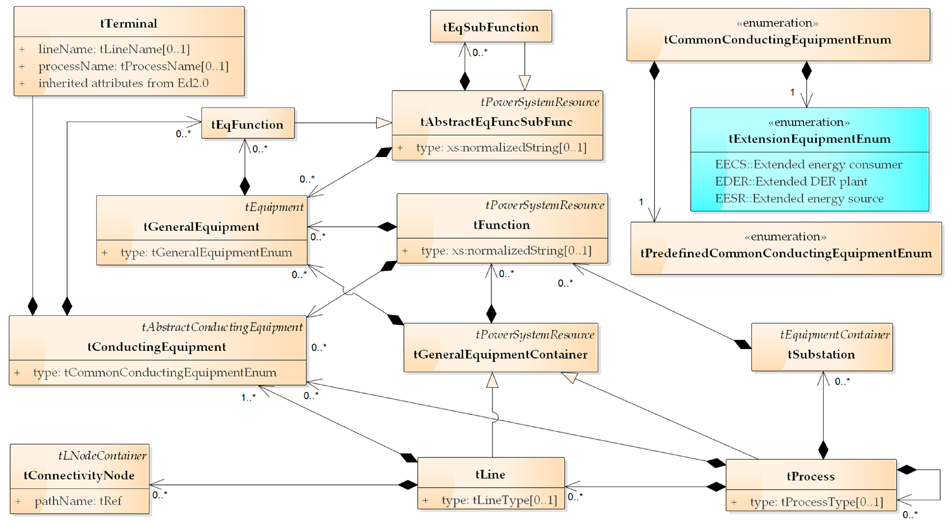
The SCL scheme in [
9] defines the
Substation element to describe the primary topology within a substation, which is in accordance with the “Substation” container and switch/node static topology in IEC 61970-301 Common Information Model (CIM) [
29], but it lacks the transmission or distribution lines. As suggested in the research report [
30], it is very useful to introduce the “Line” container of CIM into the SCL. IEC TC57 has scheduled the
Process and
Line elements in IEC 61850-6 Ed2.1 (Draft) to support other application areas than substations, which are shown in
Figure 3.
The Process element is a logical node container, which can be used for other processes than substations or to group several substations into parts of a power grid. It can be recursively used, and its type attribute can indicate the type of the process part/process object identified via the name attribute. It is recommended that the standards for the application areas standardize the type attribute values. The Line element is another logical node container, which can be used to model the lines between substations. It can contain equipment elements modelling the line segments, general equipment, and connectivity nodes.
This paper applies the
Substation,
Line, and
Process elements to describe the parts of the distribution network. The
Line element contains the distribution line segments that comprise the conductors, series compensators, current/voltage transformers, etc. Other devices in a distribution substation are placed into the
Substation container, such as the pole-top switchgears and distribution transformers, RMUs, and switching stations. Then the
Process container is on the top layer of grouped
Lines and
Substations, as shown in
Figure 4.
Distributed applications in the DAS can flexibly select Lines and Substations to describe the required topology, i.e., the aforementioned adjacent switches or IFG topology. The Substation element is bound with a physical asset like a pole, a RMU, or a cabinet. Normally, each asset has a unique identity to confirm the topological position of a distribution substation. As the distribution substation always corresponds to a central IED, the unique ID is very useful to associate the IEDs with the primary network.
This paper extends the conducting equipment with type codes EESR (Extended Energy Source), EDER (Extended Distributed Energy Resource Plant), and EECS (Extended Energy Consumer), which are shown as the blue boxes in
Figure 3. With them, it is possible to describe where this equipment is connected to the distribution grid and the externally visible data through the attached LNs. EDER means there is a DER plant connected to this electrical point, and the attached LNs from [
13] indicate the characteristics at the Point of Common Coupling. For example, the LN DCRP is short for the DER plant corporate characteristics at the Electrical Connection Point (ECP), DOPR is short for the DER plant operational characteristics at ECP, and DOPM is short for the DER plant operating mode at ECP, and so on. LNs attached to EESR and EECS can be extended as requirements of the DAS, obeying the rules in [
12]. Other equipment types like overhead and cable line segments (LIN, CAB), voltage and current transformers (VTR, CTR), etc. have already existed in [
9].
3.2. Configuration Contents
The SCL scheme supports the distributed applications by defining the topology, the communication system, the functional parameters, and the data models. The neighborhood or IFG topology and function-related LNs are presented in the Process section. The communication parameters of related IEDs are described in the Communication section. The adjacent or remote IEDs’ communication servers, Logical Devices (LD), LNs, datasets, and control blocks are described in the respective IED section. Hierarchical data models of the presented LNs, Data Objects (DO), and Data Attributes (DA) are detailed in the Data Type Templates section.
Theoretically, if an IED knows the communication parameters of another IED, it can discover all the servers, LDs, LNs, DOs, DAs, data-sets, and control blocks from it through the ACSI services such as
GetServerDirectory,
GetLogicalDeviceDirectory,
GetLogicalNodeDirectory, etc. However, this on-line discovery slows down the configuration process. To simplify the configuration processes of IEDs and to use the bandwidth more efficiently, it is recommended that only the distributed function-related LNs, datasets, control blocks, and data types of other IEDs shall be known to the requesting IED. Further, it is recommended to configure the relevant information through SCL. According to the IED types, the configuration contents are summarized as in
Table 1.
To further explain the configuration contents, we take IED0 in
Figure 2 as an example and assume it belongs to Type
D1. It parses the
Substation and
Line section beneath the
Process section. It learns that its local switch S1 is adjacent to S6, and S6 is monitored by IED1 through the associated LNs IED1Ctrl/CSWI2, IED1Meas/MMXN2, etc. Likewise, IED0 learns the topology information about S2 and S3. The whole topological configuration acquired by IED0 is shown in
Table 2.
Then, IED0 learns the communication parameters (the protocol-specific communication addresses) of IED1, IED2, and IED3 from the Communication section. The needed LNs, datasets, and control-blocks related to these datasets are both obtained from the IED sections of IED1, IED2, and IED3. Data structures of the needed LNs are acquired from the Data Type Templates section. The associations between the IEDs and needed datasets are listed in
Table 3.
Afterwards, IED0 establishes communication sessions with IED1, IED2, and IED3. It can read the switching status of S4 via the service
Get Data Values (IED1Ctrl/CSWI2.Pos [ST]), where [ST] means the Functional Constrained Data (FCD) about status values, but, in practice of IEC 61850, the FCDs like “IED1Ctrl/CSWI2.Pos [ST]” are usually packed into a data-set and transmitted to IED0 through the REPORT or GOOSE service. Data flows between IEDs shall be configured via the
ClientLN element, indicating client LNs for the REPORT-control-block; the
IEDName element, indicating subscriber IEDs for the GOOSE-control-block; and the
ExtRef element, defining the external signals for a logical node in the
Inputs section. This data flow is modeled purely on an SCL level and cannot be changed until the SCL file is updated. If the data flow must be dynamically modified with the real-time topology of an IFG, it should be additionally modelled on the IEDs’ LN data by means of data objects of the Common Data Class (CDC)ORG (Object Reference Setting, see [
11]), which are settable online.
If IED0 is designed to control switches connected to other IEDs, it can make use of the CONTROL or GOOSE service. It is up to the time performance requirements of the distributed applications to decide which service is preferred. The GOOSE service is more appropriate for transmitting the time-critical status information from one source to multiple receivers, like the control commands and fault detection results. Other less time-critical information is delivered via the REPORT service, such as the switching status, the current, voltage, and power measurements. In cases of REPORT and GOOSE services, the membership and structure of the data set shall be known to both the client (subscriber) and the server (publisher).
3.3. CID File Design
The configuration files of a DAS use the extended SCL scheme and the proposed configuration contents. There are six types of files: ICD (IED Capability Description), IID (Instantiated IED Description), SSD (System Specification Description), SCD (System Configuration Description), CID (Configured IED Description), and SED (System Exchange Description) files. Above all, the CID file for an IED also includes the information from its neighbor IEDs or other more IEDs. If we are using the GOOSE or REPORT service, the CID file would also need to comprise the description of the GOOSE or REPORT message in the source (namely, a part of the IED section of the source, which is the GOOSE/REPORT-control-block and the data-set). A CID file instance is designed and partly shown in
Figure 5.
4. Automatic Identification and Configuration Process of IEDs
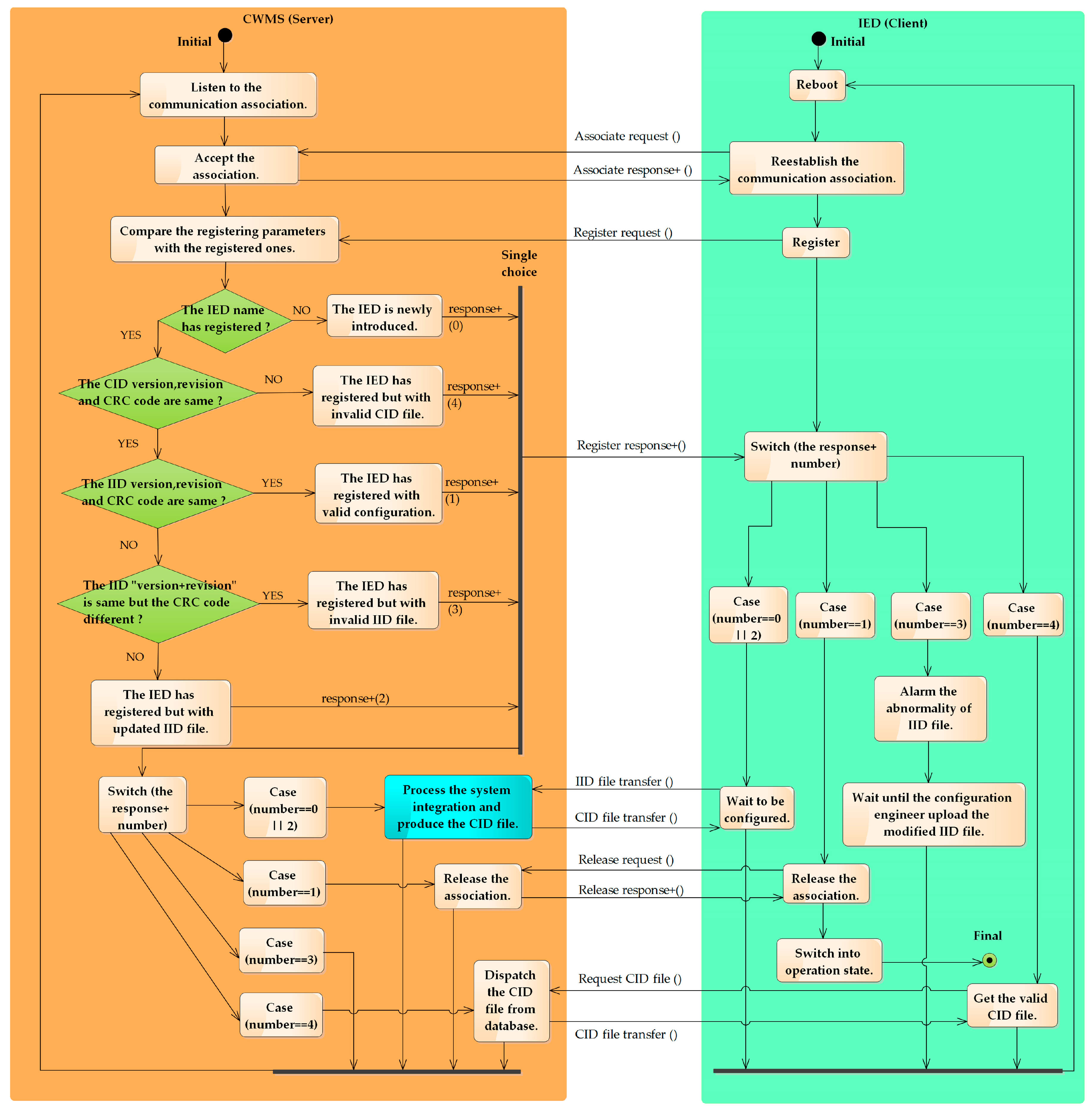
During the IED automatic identification, there exist the following rules to be followed.
All the configuration files transferred between the configuration workstation and the feeder IEDs can be locally or remotely uploaded/downloaded, but, as aforementioned in
Section 2.3, a remote approach is preferred.
The remote configuration workstation can be any node in the communication network, but the master station is a better choice because it always needs the system configuration files and has a solid foundation for cyber and physical security. Thus we set up the remote Configuration Workstation at the Master Station (called CWMS for short).
Typically, each distribution substation is equipped with one or more IEDs in the advanced DAS, but there is only one central IED for each distribution substation. It collects the station-wide data and communicates with other IEDs to perform the distributed applications. The configuration process in this paper is aimed at these central IEDs.
4.1. Automatic Identification of IEDs
The Unique Identities (UID) of distribution substations and primary devices have already been assigned by the DAS planning personnel. The UIDs are provided to the configuration engineers both on site and at the master station. The central IED should have a unique ID, which is the same as the monitored distribution substation for the ease of locating its topological position. The information technology engineer has planned the communication address of each IED and a default address for the CWMS, which should also be known to configuration engineers.
On site, the configuration engineer configures the IED by creating an IID file from the ICD file. The Substation section is instantiated according to the UIDs, the single line diagram of this distribution substation, and the LN allocations to the primary equipment. The Communication section is instantiated by communication parameters of this IED. The IED section is instantiated by assigning the names and numbers to the server, access points, LDs, LNs, etc. The Data Type Templates section as well as data-sets and control-blocks are taken from the ICD file. Therefore, the IID file is instantiated with its own distribution substation, communication parameters, and data models but has no data flow with other IEDs. It should be noted that the CWMS is a dedicated server for each IED so its communication address is always configured.
When an IED reboots or re-establishes a communication session to the CWMS, it will send a register request to the CWMS. The latter will check the configuration version and the state of the IED to determine the subsequent configuration process. Register parameters and explanations are listed in
Table 4.
The automatic identification of an IED is successfully done as shown in
Figure 6. If the identification is unsuccessful with a negative response, the IED will repeat the register service for predetermined times. If it still fails, the IED will alarm the configuration engineers to solve the error manually. The configuration process is represented as the blue box in
Figure 6, and the details are proposed in following
Section 4.2 and
Section 4.3.
4.2. First Configuration for an IFG System
When a group of IEDs, IED1~IEDn, are introduced into an IFG system for the first time, they should be configured integrally as follows.
The configuration engineer at the master station has obtained the single line diagram of the IFG from the planning personnel. An SSD file of the IFG is produced according to the extended SCL scheme.
When all the IED1 to IEDn have registered and their IID files have been received successfully, the configuration engineer starts the system integration. The SSD file and IID files (1 to n) are input to the system configuration toolkit. The toolkit correlates the IID files with specific distribution substations based on the UIDs. It establishes the data flows between different IEDs to fulfill the distributed functions.
The SCD file, IED names (1 to
n), and IED types (1 to
n) are put into the IED configurator. It makes the SCD file into a CID file for each IED. The CID file contains the topology information and data flow, as defined in
Section 3.2 and
Section 3.3.
When CID files (1 to n) have been generated, they are delivered to IED1~IEDn remotely. IED1~IEDn will restart to register and enable the new CID files automatically.
4.3. Configuration Updates for System Changes
Any change of the primary topology or IEDs within an IFG will result in a renewed SCD file. IEDs’ CID files that are affected by the SCD changes must be updated.
4.3.1. Update for Static Topology Changes
When the static topology is changed, the configuration engineer should be informed of the new single line diagram. There exist the following scenarios.
- (a)
If there is a new distribution substation added into this IFG, a new IED will be recognized and configured.
- i.
The SSD file is renewed according to the new diagram.
- ii.
The configuration engineer retrieves the current SCD file from the SCD database and inputs the current SCD file, new IID file and renewed SSD file into the system configurator. Then, the system is re-integrated and a renewed SCD file is output.
- iii.
The renewed SCD file and the new IED name and type are input onto the IED configurator. Then, the new CID file for this IED is output. Other existing IEDs having data flows with this IED also need to update the CID files, wherein the CID files are produced with the method in
Section 4.2.
- iv.
The new and updated CID files are remotely uploaded onto respective IEDs.
- (b)
If there is an obsolete distribution substation removed from this IFG, the IED deletion cannot be recognized automatically but should be informed to the configuration engineer manually. The engineer should subtract the distribution substation and the IED from the current SCD file, forming the renewed SCD file. Existing IEDs that previously had data flows with this IED need to update the CID files, which are produced with the method in
Section 4.2.
- (c)
If there are topology changes within a distribution substation, the IID file of this IED will certainly be updated and recognized. Then the configuration process is the same as scenario (a).
4.3.2. Update for a Modified/Substituted IED
When the static topology remains unchanged, an existing IED may still be modified for upgrade or be substituted for depot maintenance, etc. The IID file of this IED will surely be updated and be recognized via the register service. Then the configuration process is the same as scenario (a) in
Section 4.3.1.
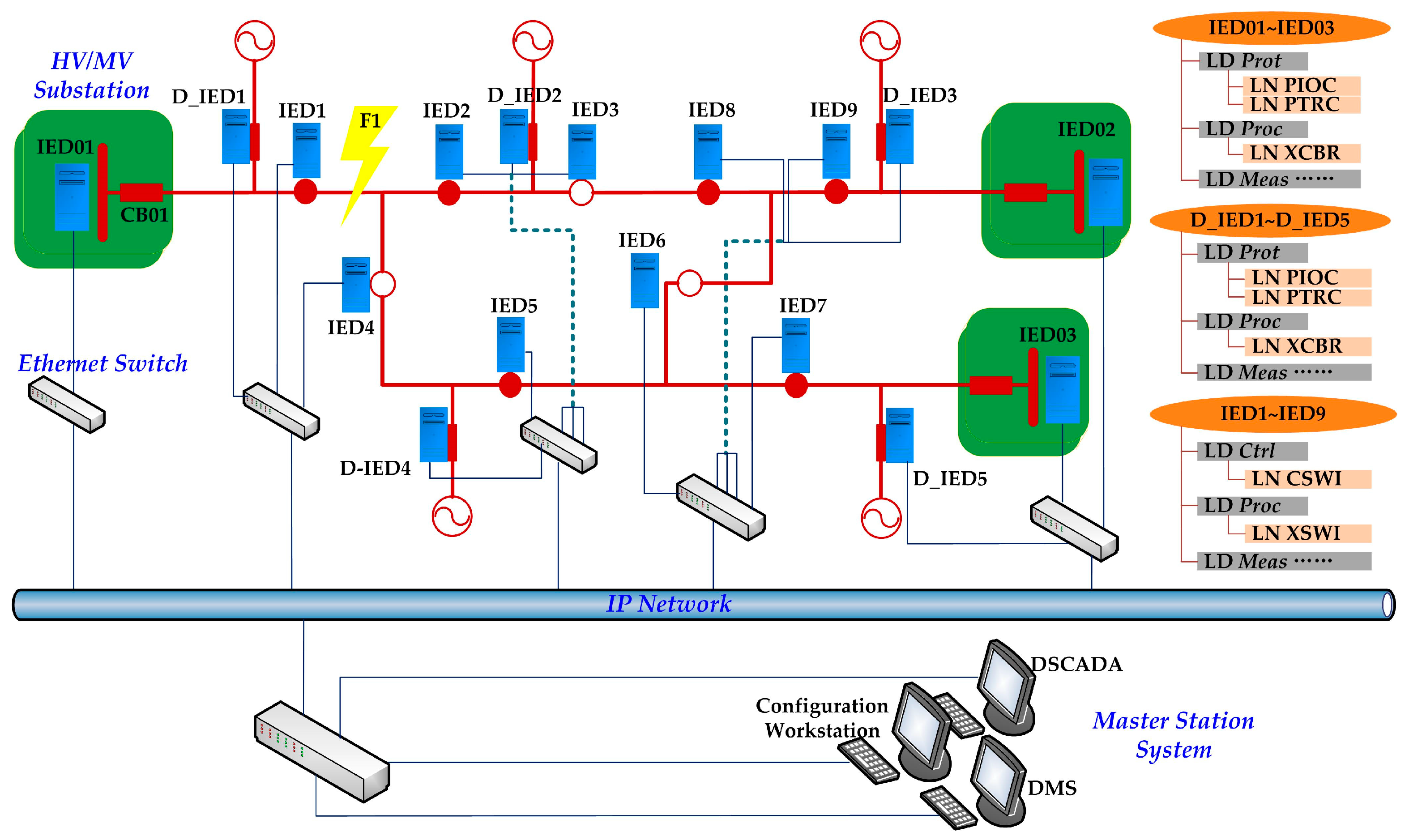
5. Case Study
A simulated DAS is shown in
Figure 7. The DTT based anti-islanding function is used as the test case and allocated at IED01–IED03. They should transfer the trip signals to related IEDs among D_IED1–D_IED5, according to the real-time topology of this IFG. All the other IEDs just need to report their switching status to IED01–IED03 and be controlled by them.
IED01–IED03 belong to Type D2 and other IEDs belong to Type B. All the IEDs have registered and been configured by the aforementioned CID file instance.
During the test, the DTT signal is transferred through a GOOSE message. When configuring the GOOSE data flow, D_IED1–D_IED5 are the possible subscribers of the DTT message from IED01–IED03. Thus the names of D_IED1~D_IED5 are all configured onto the GOOSE-control-blocks of IED01~IED03. In the
Inputs section of each XCBR (LN: Circuit Breaker) in D_IED1–D_IED5, all the possible source references of the DTT signals are listed. That is, the DO references of “PTRC.Tr” (Trip signal of the LN: Protection Trip Conditioning) from IED01–IED03 are configured via the
ExtRef elements. The datasets and GOOSE control blocks about the “PTRC.Tr” of IED01~IED03 are also configured onto each of D_IED1–D_IED5. Above all, the XCBR class is extended by a data object “XCBR.TrRef” to determine the actual trip signal, which should be received due to the real-time topology. It is a single choice from the possible sources list in the
Inputs section, and the extension is shown in
Table 5.
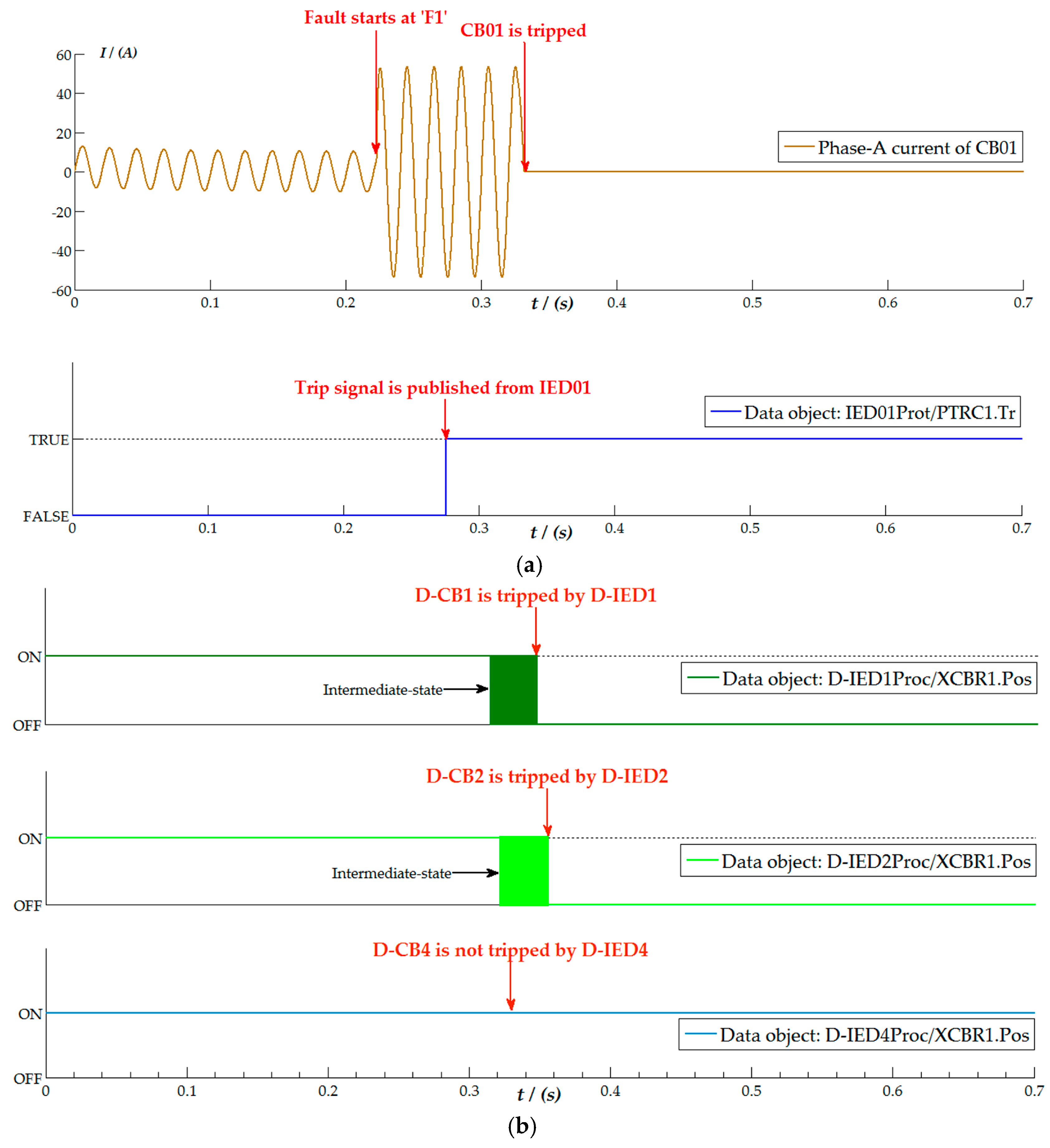
Step 1: The tie-switches are set as S3 and S4. IED01–IED03 have got all the switches’ statues and calculated the real-time topology. IED0 is responsible for transferring the trip signals to D_IED1 and D_IED2. Therefore, it remotely sets the data:
Likewise, IED02 sets the data:
IED03 sets the data:
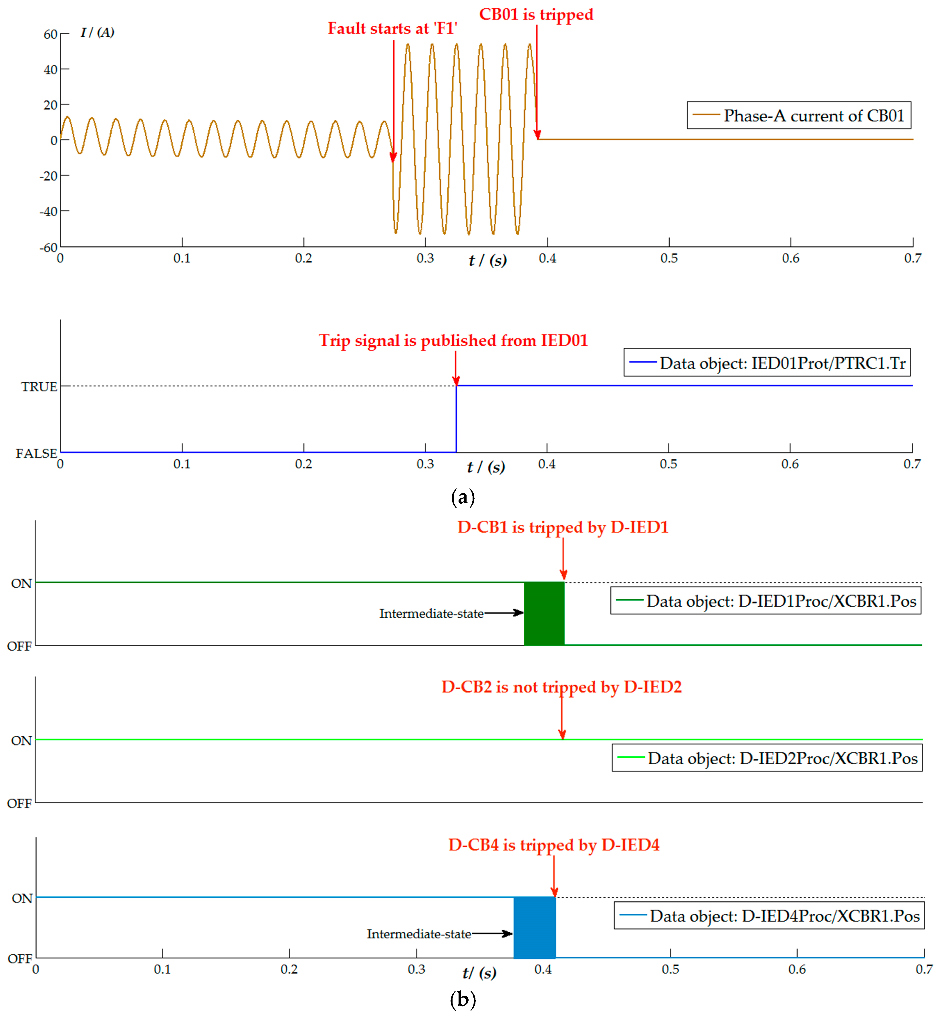
When a short-circuit fault occurs at the point “F1”, the data attribute “IED01Prot/PTRC1.Tr.general” becomes TRUE, and it will be transferred via a GOOOSE message and be subscribed by D_IED1 and D_IED2. They extract the Boolean value of current “TrRef” from the GOOSE data and then trip the grid-on/off breakers. The related test results are shown in
Figure 8.
Step 2: The tie-switches are altered as S2 and S5. IED01 has found out that it is responsible for transferring trip signals to D_IED1 and D_IED4. Thus, it remotely sets the data:
IED02 sets the data:
IED03 sets the data:
When a short-circuit fault occurs at the point “F1”, the data attribute “IED01Prot/PTRC1.Tr.general” becomes TRUE, and the GOOOSE message is subscribed by D_IED1 and D_IED4. They extract the Boolean value of the new “TrRef” from the GOOSE data and finally trip the grid-on/off breakers. Some of the test results are shown in
Figure 9.
No matter how the dynamic topology changes, it will be detected by IED01~IED03 thanks to the proposed configuration solution. Consequently, the GOOSE data flows among these responsible IEDs are built automatically in real-time and without operating the SCL files.
6. Conclusions
To make IEC 61850 support distributed intelligence in the DAS, this paper analyzes the configuration requirements and proposes the configuration solution systematically. The crucial point is that an IED should be configured with the relevant primary topology and communication system within an IFG, as well as the functional parameters and data models of peer IEDs. With the presented SCL models, the topology of an MV distribution network is appropriately described, and the new CID file is structured including the topology, communication, and functional parameters of peer IEDs. Through the configuration solution, an IED classified as Type D1 can recognize its neighbors and those classified as Type D2 can detect the real-time topology of an IFG to find out which IEDs are responsible for communicating with it. The data flows between IEDs are settable online by means of data objects of the CDC ORG in IEC 61850, which just need simple extensions of the objective LNs. The IED’s automatic identification method makes it convenient to check the configuration status and benefits the remote configuration engineering. It is advantageous that IEDs can process real-time topology and re-establish data flows independently of the master station; thus the distributed applications are performed in a more autonomous and efficient way. In addition, the data flows accompanying distributed applications are changeable online without operating on the loaded CID files unless the static topology of the IFG is modified. This is very significant for decreasing the configuration workload caused by data flow alterations, because the data flows within distributed applications are highly topology-dependent, but the dynamical topology of distribution network will change from time to time.


