Article

Active, Reactive and Harmonic Control for Distributed Energy Micro-Storage Systems in Smart Communities Homes

1
Department of Electrical, Electronic and Automation Engineering, University of Extremadura, Badajoz 06006, Spain
2
Department of Computer Architecture, Electronics and Electronic Technology, Universidad de Córdoba, Córdoba 14071, Spain
*
Author to whom correspondence should be addressed.
Energies 2017, 10(4), 448; https://doi.org/10.3390/en10040448
Submission received: 8 February 2017 / Revised: 20 March 2017 / Accepted: 24 March 2017 / Published: 1 April 2017

Abstract

:
This paper aims to provide control strategies for distributed micro-storage energy systems at the residential level to contribute to smart grid goals. A simulation model of an energy storage system (ESS) charger has been implemented to test these proposed control strategies. The smart community energy management system (SCEMS), acting as an aggregator of resources in the community according to the expected demand and production, sends to each individual home the active and reactive power set-points. Besides, in case the ESS has available capacity, once the SCEMS requirements are satisfied, it is used to absorb the harmonic current components demanded by the household circuitry. It allows a local improvement in the power quality of the demanded current, and thus contributes to the global power quality consumption of the community. Simulation results showing the operation of a local ESS at a home in a Smart Community are presented to validate the proposed control strategies.

1. Introduction

The idea of the so called Smart Communities [1,2] is supported by the following facts: the rising trend in electricity demand, the increase of distributed generation based on renewable resources and the great advance in energy storage systems research.
The energy demanded by a community could be provided by the generators owned by the consumers themselves. This can be done either directly (if the time period of consumption match that of the non-manageable energy production) or indirectly by means of an energy storage system. With a proper management, an important savings in the electricity bill will be achieved [3].
Owners of distributed generators, usually non-manageable (photovoltaic or wind units) located in the vicinity of consumers, could take advantage of selling their energy locally, or they can sell electrical energy to the market at time periods in which the price is higher, regardless of the generation timetable [4]. From the point of view of the grid, demand side management and smoothing of the power injected into the grid by the distributed generators, facilitate the distribution grid operation [5].
In this situation, energy storage systems (ESSs) are essential for the energy management system of the smart community [6]. Most of the attention in the technical literature has been paid to the research on the design of large storage capacity (10–100 MWh) equipment. However, in the last years, research has been focused on the use of distributed micro-storage systems with a smaller capacity (few kWh). These micro-storage systems, shared by several homes in a community, allow consumers to keep stored a small amount of energy to take over the peaks in its demand and to smooth the variability of their own renewable energy supply. A central smart community energy management system (SCEMS) is responsible for the control of these equipment, acting as an aggregator of resources and coordinating them to assure benefits for the whole community. The SCEMS generates and sends to each local ESS the set-points for both active and reactive power for charging/discharging, according to the demand and production.
Additionally, these systems should not get worse the power quality. Indeed, most battery chargers for ESS on the market demand harmonic currents and reactive power and, as a consequence, the massive installation of battery chargers leads to a deterioration of power quality in the distribution grid [7]. This shows the need for research into new control strategies applicable to the energy storage management system (ESMS) to guarantee that these chargers operate according to the smart grid goals and policies [8].
The objective of this work is to contribute to this line of research. Thus, control strategies for the ESMS to meet the active and reactive power set-points received from the SCEMS have been proposed. These strategies will improve the performance of the ESS and the quality of the current waveform demanded by the charger. Besides, in case the ESS has got available capacity, once the SCEMS requirements are satisfied, it is used to absorb the harmonic current components demanded by the household circuitry. It allows a local improvement in the power quality of the demanded current, and so contributes to the global power quality consumption of the community. Most bidirectional chargers found in the technical literature focus on the active power flow control and few works address a reactive power flow control. However, the benefits of including a local harmonic control strategy, operating simultaneously with the active and reactive controllers, have not been further investigated. The main contributions of the paper are:
  • The proposal of a strategy to control fundamental reactive power, able to operate properly under distorted grid voltage,
  • The harmonic control strategy with saturated function, to assure the charger safety,
  • The combination of the active, reactive and harmonic control in a global control strategy which allows the charger to operate simultaneously with P, Q and H control, and the validation by simulation of this global strategy.
The paper is structured in the following manner: first, the control strategies to control active power (P mode) and reactive power (Q mode) are presented. Then, the harmonic control (H mode) is added with the aim of compensating the harmonic consumption of the homes, contributing to improve the power quality of the network. These strategies have been implemented in a simulation model of an energy micro-storage system located at a home of a smart community. A set of simulation tests has been carried out showing the effectiveness of the strategies in different practical situations.

2. Control Strategies

The control strategies are the general rules that must be followed by the control system in order to achieve the desired converter behavior.

2.1. Active Power

The SCEMS will manage the local ESS at homes, by sending an active power set-point to each individual ESS, according to previous market negotiations. Two modes of operation can be distinguished: Grid to battery mode (G2B-P mode) when the ESS is extracting active power to charge the batteries, and Battery to grid mode (B2G-P mode), when the ESS is injecting active power from the batteries into the grid. The sign criterion for the set-point is positive in the G2B-P mode (Pref > 0), and negative in the B2G-P mode (Pref < 0).
A Direct Sinusoidal Current (DSC) control strategy is proposed [9]. This strategy aims to do that the current demanded or injected into the grid to be in phase with the fundamental component of the grid voltage. It guarantees, on the one hand, that the ESS will operate with unity displacement power factor (dPF), and on the other hand, that the charger current will have no harmonic content.
The reference charger current is [9]:
i c h P , r e f = P r e f U S 1 2 u S 1 d
where US1 is the fundamental component of the grid voltage and uS1d is the instantaneous value of the fundamental component of the grid voltage.
A single-phase Second-order Generalized Integrator Phase-Locked-Loop (SOGI-PLL) system [10] is employed to extract the fundamental component of the grid voltage.

2.2. Reactive Power

Local ESS at homes of smart communities can be used as distributed storage sources to provide voltage control or to improve globally the power factor of the community. Thereby, the SCEMS is responsible for calculating a fundamental reactive power set-point, Q1ref, for each individual ESS. The modes of operation are G2B-Q mode, when the ESS is absorbing fundamental reactive power from the grid (Q1ref > 0) and B2G-Q mode, when it is injecting fundamental reactive power to the grid (Q1ref < 0).
A novel quadrature sinusoidal current (QSC) control strategy is proposed in this case, equivalent to the previous SC strategy, but taking over the reactive power, instead of the active power set-point. This strategy assures that the current demanded or injected into the grid will be sinusoidal and in quadrature with the fundamental component of the grid voltage. The reference charger current with this strategy is obtained as:
i c h Q , r e f = Q 1 r e f U S 1 2 u S 1 q
where uS1q is the instantaneous value of the fundamental source voltage, being +90° phase shifted from uS1d.
This component can be calculated by using the SOGI-PLL proposed in [10], since the output signals of this single-phase PLL are the fundamental component of the input signal and another component with the same amplitude but with a phase shift of 90°.

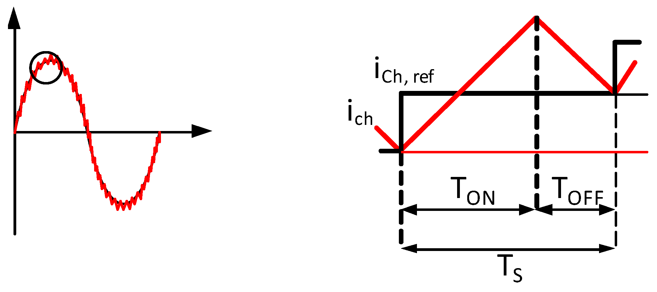
2.3. Additional Harmonic Control Strategy

If the ESS is below 100% capacity, it can be in charge of an additional function concerning the power quality improvement of the current demanded by each home and so, contributing to the global power quality consumption of the community. This harmonic control function has only a unidirectional operation mode, from the charger to the load: Battery to load mode (B2L-H mode).
It is important to note that this control strategy does not receive a set-point from the SCEMS, since it proposes a local compensation of the harmonic content demanded by the household circuitry. Since each home in the community has an ESS, this local compensation contributes to achieve a global compensation in the community.
A total harmonic compensation (THC) control strategy is proposed. It aims to provide as a harmonic reference charger current the whole harmonic spectrum of the current demanded by the house, neglecting the fundamental frequency. The advantage of this strategy comparing to selective harmonic compensation strategies [11] is that it can be applied for loads with unknown harmonic spectrum and requires more simplified control algorithms.
If the harmonic reference current added to the current for P and Q control exceeds the nominal current of the charger, Ich,n, the reference current has to be limited to prevent overload. The maximum Root Mean Square (RMS) harmonic charger current is obtained from:
I c h H , max = I c h , n 2 I c h P 2 I c h Q 2
where Ich-P and Ich-Q are the RMS charger current components responsible for the P and Q control, respectively. Taking into account this limit, the reference harmonic charger current will be obtained from the following expression:
i c h H , r e f = ( i L i L 1 ) if   ( i L i L 1 ) R M S I c h H , max i c h H , r e f = ( i L i L 1 ) I c h H , max ( i L i L 1 ) R M S if   ( i L i L 1 ) R M S > I c h H , max
where, iL is the load current demanded by the house, iL1 its fundamental component, obtained from the SOGI-PLL and (iLiL1)RMS is the RMS value of (iLiL1).

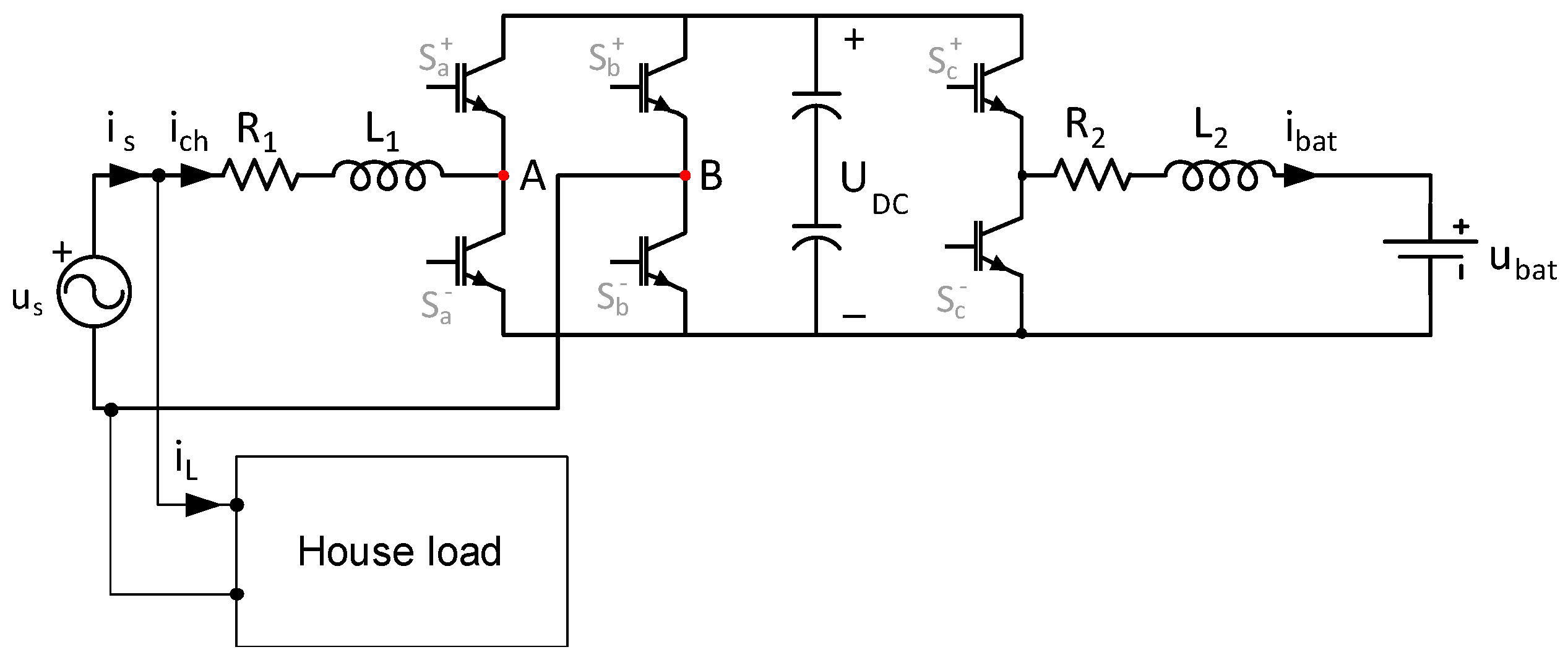
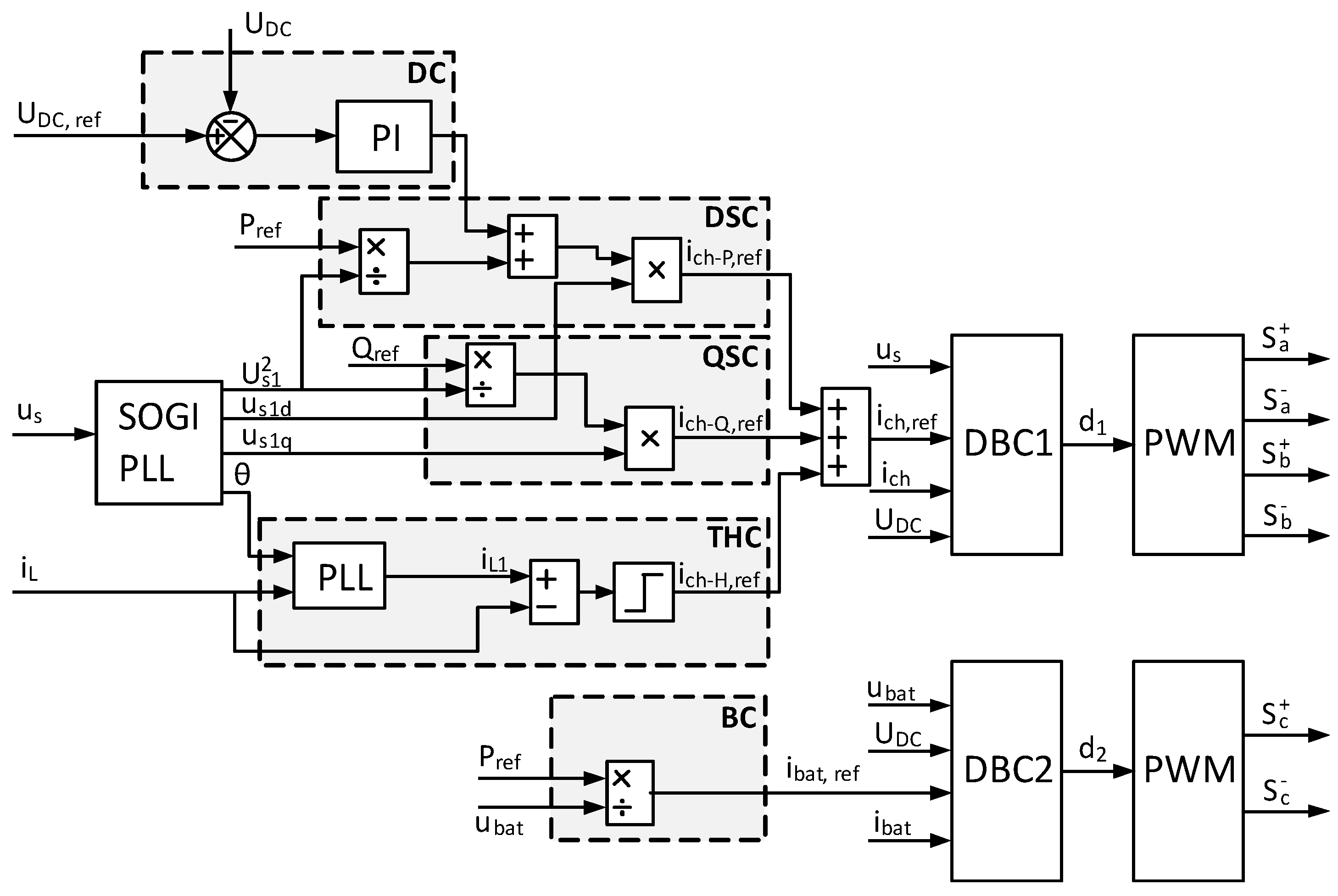
3. ESS Power Structure and Control System

A single-phase energy micro-storage system, based on batteries, located at a home of a smart community has been developed. It receives P and Q set-points from the SCEMS and controls the current demanded/injected from/into the grid using the energy stored in the battery.

3.1. Topology

The ESS has a single-phase topology (Figure 1). It uses two power converters: one DC/DC converter to manage the charge and discharge of the battery and to adapt the battery voltage ubat to the DC-link voltage UDC; and an AC/DC converter to interface with the AC grid. The DC/DC converter has a half bridge bidirectional buck-bust DC/DC topology, consisting of two transistors (Sc+ and Sc) and one inductor L2 (with resistance R2). The AC/DC converter is a full-bridge Voltage Source Inverter (VSI) formed by four switches Sa+, Sa, Sb+, Sb and an inductor L1 (with resistance R1). The current drawn from the grid is ich and the current absorbed by the battery is ibat.
It is considered a typical consumer having 4.6 kVA contracted power (one of the standard values in Spain). It is estimated the ESS to be rated at a half of that value, so the ESS is rated at 2.3 kVA, 230 V. Therefore, the RMS nominal charger current Ich,n is 10 A and the main parameter values are shown in Table 1. These parameter values has been selected according to the design criteria proposed in [12].

3.2. Global Control Strategy

The block diagram of the general control strategy is displayed in the left side of Figure 2. The control algorithm requires the measurement of several variables: the source voltage, uS, the load current demanded by the house, iL, the battery voltage, Ubat and the DC-link voltage, UDC. In addition, the other inputs are the set-points Pref and Qref provided by the SCEMS and the RMS nominal charger current, Ich,n which has a known value. In case P control or Q control are not required, the corresponding set-points are void. If harmonic control is not precise, the iL measurement is cancelled.
One can notice that there are no potential conflicts among the active, reactive and harmonic compensation, since each control is devoted to a different component of the charger current. Indeed, the lack of interaction is one of the advantages of the proposed global control strategy, which allows the charger to operate simultaneously with P, Q and H control.
The SOGI-PLL block obtains US1, uS1d and uS1q from the grid voltage uS. The DSC block implements the active power from Equation (1) and adds a signal from the DC control block. This block has the objective of maintain a constant DC-link voltage; it is constituted (see at the top of the figure) by a proportional-integral (PI) controller, whose input is the difference between real and desired DC-link voltage. QSC and THC blocks (shown below the DSC) implement the reactive power control from Equation (2) and the harmonic control from Equation (4), respectively. The outputs of these three blocks are added to obtain the reference for the AC/DC converter: the reference charger current ich,ref. The BC block (at the bottom on the figure) divides the Pref by ubat, obtaining the reference current for the DC/DC converter: the reference battery current ibat,ref.

3.3. Switching Signal Generation

A dead-beat control technique is used to follow the reference currents ich,ref for the DC/AC converter and ibat,ref for the DC/DC converter. Dead-beat technique is a well-known discrete control technique based on the idea of reduce to zero the error in the controlled variable at the end of the control period. Figure 3 illustrates the operation principle applied to follow ich,ref in one switching period TS. At the beginning, ich,ref is compared with the measured or real charger current ich. The evolution of ich is determined by the states of the switches Sa and Sb. Indeed, when Sa+ and Sb are turned on (Sa on-state) UAB = UDC and when Sa and Sb+ are on (Sa off-state) UAB = −UDC; of course the operation of the two switches of one leg is complementary. Two approximation are considered: on one hand, voltage across R1 can be ignored compared to uL and, on the other hand, the grid voltage uS can be considered constant during the switching period TS. Therefore, an approximately constant voltage is applied to inductance L1: uSUDC in the Sa on-state and uS + UDC in the Sa off-state. Taking into account that uL1 = L1 dich/dt, the current ich will be a positive ramp in the first case and a negative ramp in the second case; in both cases the slope value is 1/L1. The duty cycle (d1 = Ton/TS) necessary to achieve ich to be equal to ich,ref at the end of TS can be calculated from the fact that the following equality must be satisfied:
i c h , r e f i c h = ( u S U D C ) d 1 T S L 1 + ( u S + U D C ) ( 1 d 1 ) T S L 1
and the resulting expression for d1 will be:
d 1 = ( u S + U D C ) T S ( i c h , r e f i c h ) L 1 2 T S U D C
This operation is executed by the block DBC1 (Dead-Beat Controller 1) in Figure 2, whose inputs are uS, ich, ich,ref and UDC and whose output signal is d1.
Analogously, the duty cycle d2 for the DC/DC converter is obtained, resulting:
d 2 = u b a t T S ( i b a t , r e f i b a t ) L 2 T S U D C
This operation is executed by the block DBC2 (Dead-Beat Controller 2) in Figure 2, whose inputs are ubat, ibat, ibat,ref and UDC; and whose output signal is d2. Finally, both values d1 and d2 are converted into the corresponding switching signals for the gates of the converter switches by means of the Pulse Width Modulation (PWM) blocks: Sa+, Sa, Sb+, Sb for the AC/DC converter and Sc+, Sc for the DC/DC converter.

4. Simulation Results

A simulation model of the ESS has been developed in Matlab-Simulink according to the topology and control system described before. For 10 kHz switching frequency (switching period TS = 10−4 s), the time step for the simulation was taken Tm = 10−6 s. The nominal RMS value of the fundamental grid voltage is 230 V, and the harmonic components are 5% 3rd harmonic, 4.5% 5th harmonic and 4% 7th harmonic. The total harmonic distortion (THD) is 7.83%, complying with the limits proposed in IEC 61000-2-2:2002 [13]. To demonstrate the behaviour of the system, the simulation has been conducted in four cases:
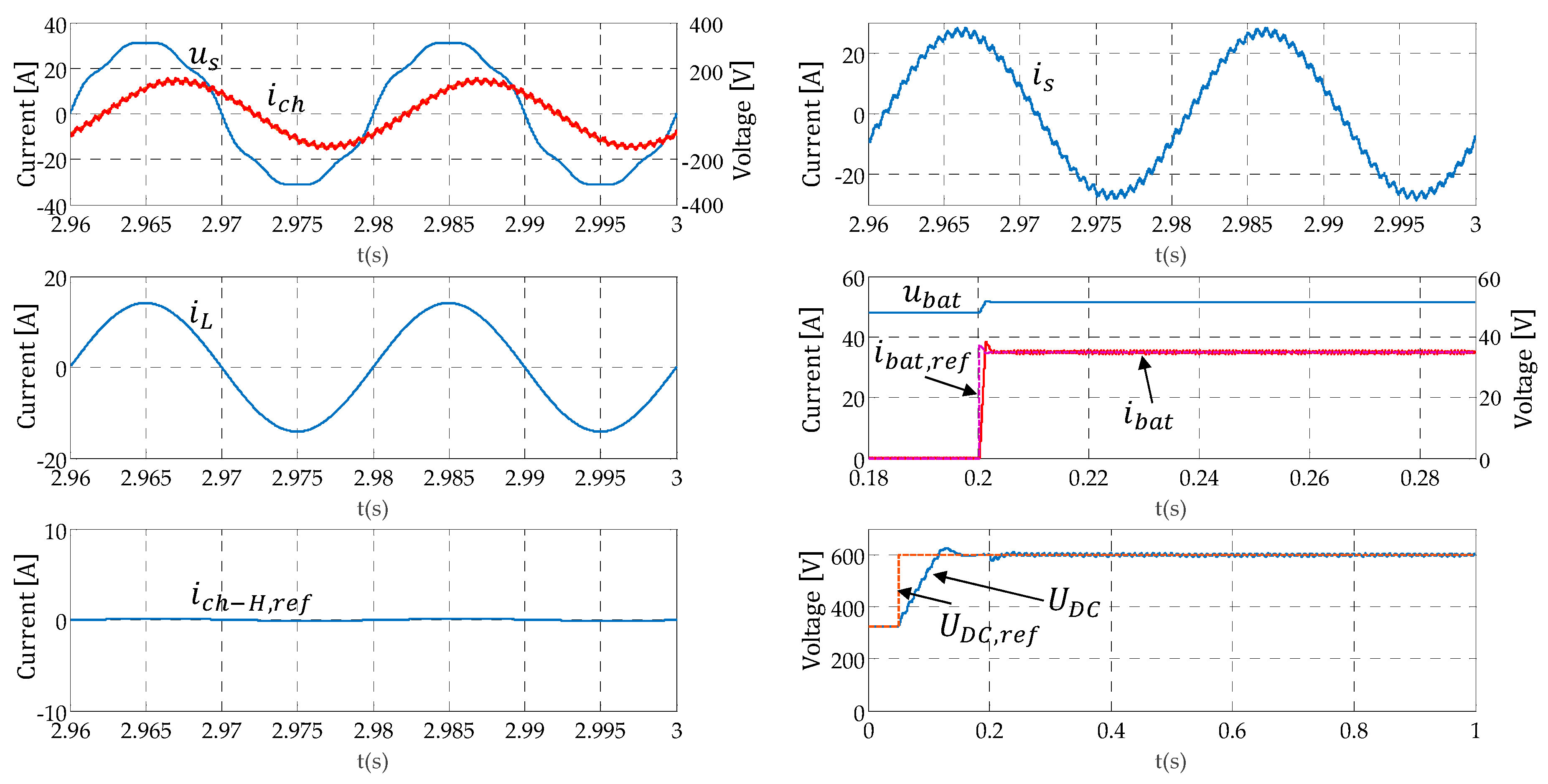
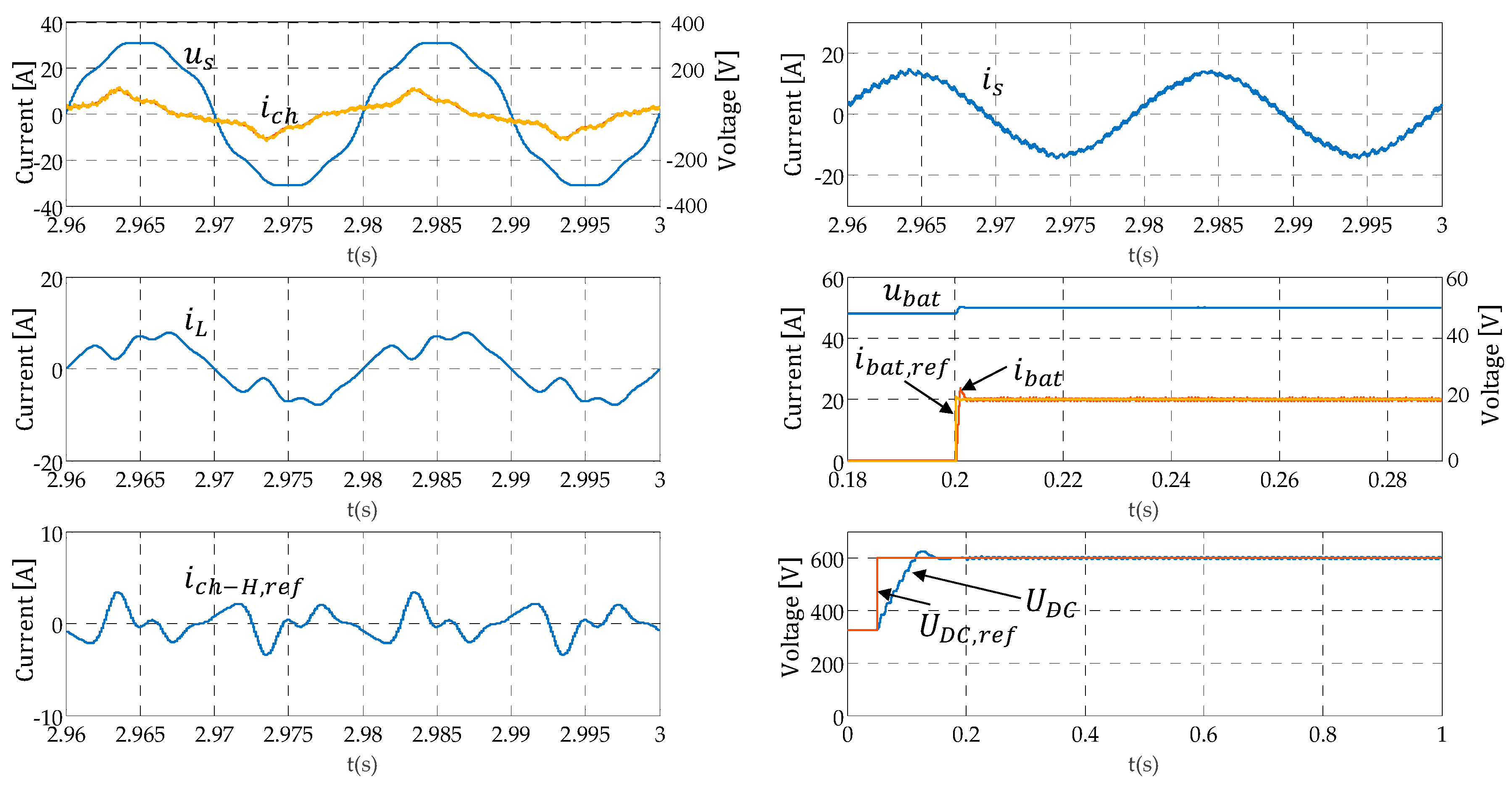
  • Case A. Charging the battery and demanding fundamental reactive power: Pref = 1800 W and Q1ref = 1400 VAr. House demand without harmonics: IL = 10 A (perfectly sinusoidal, i.e., iLh = 0).
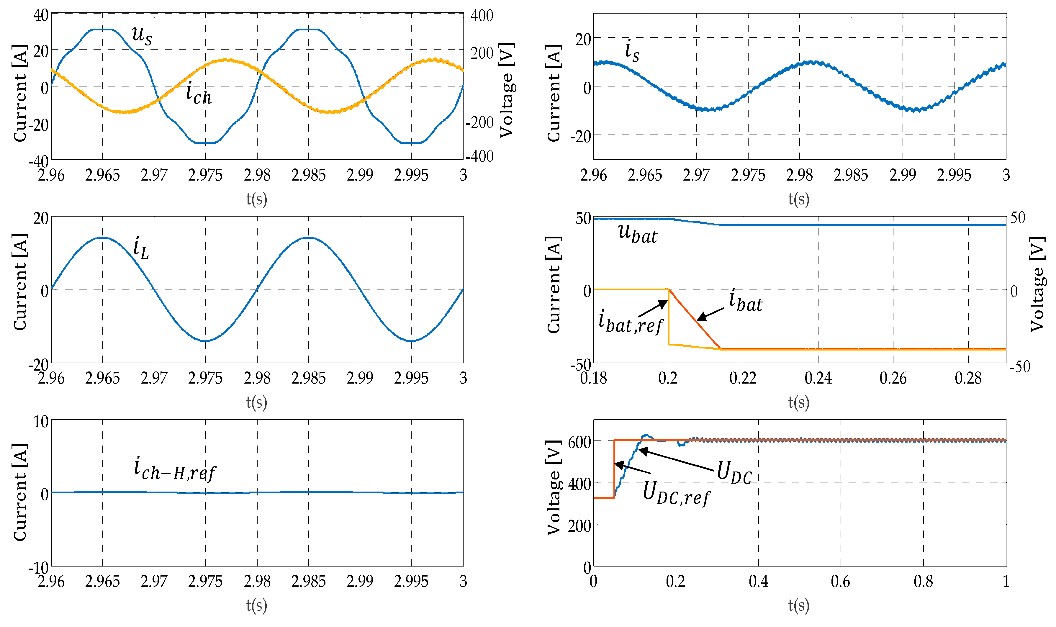
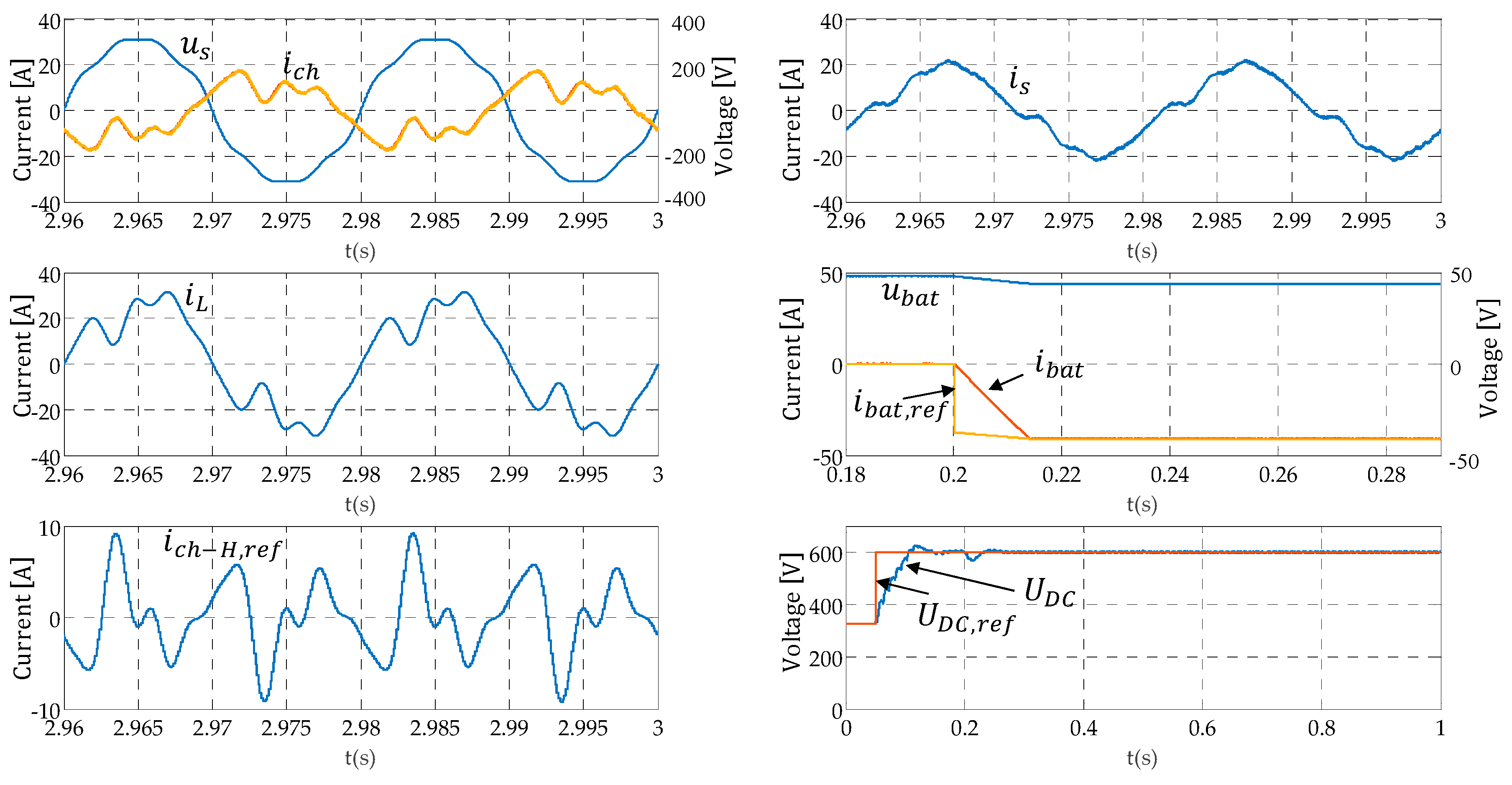
  • Case B. Discharging the battery and injecting fundamental reactive power: Pref = −1800 W and Q1ref = −1400 VAr. House demand without harmonics. IL = 10 A (perfectly sinusoidal, i.e., iLh = 0).
  • Case C. Charging the battery and injecting reactive power: Pref = 1000 W and Q1ref = −600 VAr. House demand with usual odd harmonics contents [14] below 11th order specified in Table 2; with RMS value of load current IL = 4.996 A.
  • Case D. Discharging the battery and demanding reactive power: Pref = −1800 W, Q1ref = 1100 VAr. House demand with the same usual harmonics contents; now with IL = 19.98 A.
Figure 4, Figure 5, Figure 6 and Figure 7 show the simulation results for every case. From top to bottom and from left to right the figures present: uS, ich, iL, ich-H,ref and iS in steady state and ubat, ibat, ibat-ref, UDC and UDC-ref from their initial values to steady state. It is supposed that the battery is initially charged at its nominal value (48 V). On the other hand, the AC/DC converter is supposed to operate initially as a rectifier, so as the DC-link voltage is initially at the corresponding rectified voltage ( 230 2 = 325   V ). Simulation starts at t = 0 and at t = 0.05 s the DC block starts to operate leading the DC-link voltage to its nominal value (600 V); this objective is achieved and then, at t = 0.2 s the all three modes (P, Q and H) are activated. To ease the visualization of transient behavior, the evolution of UDC and UDC-ref are shown from t = 0 to steady state and ubat, ibat and ibat-ref are shown from t = 0.18 to steady state (in this last case to show in more detail the evolution around t = 0.2 s). On the other hand, the evolution of uS, ich, iL, ich-H,ref and iS are shown for two cycles (40 ms) from 2.96 s to 3 s, when the steady state condition is reached. In all cases, the charger current ich follows the reference ich-ref accurately although the source voltage is distorted, so the ESS complies with the limits for harmonic currents produced by equipment connected to public low-voltage systems [15].
In cases A (Figure 4) and B (Figure 5) ich-H,ref is null, so H function is not needed and, therefore, the charger draws from the grid a current (is) that differs from a sinusoid only in the switching ripple. In case C (Figure 6) the requirements from the SCEMS and the harmonic content of the house is compatible with the ESS nominal current, so the ESS performs a full compensation and the current demanded from the grid (iS) differs from a sinusoidal only in the switching ripple. Its harmonic content is shown in Table 3. As one can see, THD is reduced from 30.67% to 2.94%. On the other hand, in case D (Figure 7) the requirements are such that it is not possible to fully attend to the harmonic compensation requirement, so ESS performs a partial compensation and in this case the current demanded from the grid (iS) is not sinusoidal. Its harmonic content is shown in Table 4. As one can see, THD is reduced to 14.56%.
Power terms according to power definitions proposed in Std. IEEE-1459:2010 [16] are collected in Table 5 for the four cases. S is the apparent power, P is the active power, N is the non-active power, Q1 is the fundamental reactive power, PF is the power factor and dPF is the displacement power factor.

5. Conclusions

Control strategies for local energy micro-storage systems regarding active power and reactive power control in the homes of smart communities have been proposed. Additionally, a control strategy to reduce harmonic content in the current demanded by the houses is presented. This control only comes into operation once the ESMS verifies that the ESS has available capacity and, if necessary, saturates the harmonic load current compensation to ensure that the charger does not exceed its nominal parameters. The main contributions of the paper are the proposal of the QSC strategy to control fundamental reactive power and the saturated THC strategy, to assure the charger safety. A 2.3 kVA single-phase energy micro-storage system based on batteries, located at a home of a smart community, has been implemented by simulation to test the proposed strategies. Simulation results showing the currents injected/demanded by the ESS charger following the set-points provided by the SCEMS with active, reactive and harmonic control are presented under distorted source conditions. These results validate the correct operation of the proposed control strategies and demonstrate that local ESS in smart communities can contribute to the smart grid goals, providing ancillary services and improving the power quality locally, thanks to the performance of the SCEMS.

Acknowledgments

This work was supported by the Spanish Ministerio de Economía y Competitividad and Fondo Social Europeo, FEDER, under Project TEC2013-47316-C3-3-P.

Author Contributions

Maria Isabel Milanes-Montero and Fermin Barrero-Gonzalez conceived, designed and supervised the simulation tests and wrote the paper, Jaime Pando-Acedo performed the simulation model and tests, Eva Gonzalez-Romera analyzed the data and simulation results, Enrique Romero-Cadaval contributed analysis tools and supervised the simulation model, and Antonio Moreno-Munoz collaborated with the paper review.

Conflicts of Interest

The authors declare no conflict of interest.

Nomenclature

diDuty cycle obtained from the dead-beat controller number i
ibatBattery current
ichCharger current
ich-PCharger current with P mode control
ich-Q,Charger current with Q mode control
ich-HCharger current with H mode control
Ich,nNominal current of the charger
Ich-H,maxMaximum RMS charger current available for H mode control
iLLoad current demanded by the house
iSSource or grid current
PrefActive power set-point
Q1refFundamental reactive power set-point
TSSwitching period
TmTime step for simulation
UbatBattery voltage
UDCDC bus voltage
uSSource or grid voltage
uS1dFundamental component of the grid voltage
uS1qFundamental component of the grid voltage, +90 degrees phase shifted

References

  1. Davies, R.; Sumner, M.; Christopher, E. Energy storage control for a small community microgrid. In Proceedings of the 7th IET (Innovation, Engineering, and Technology) International Conference on Power Electronics, Machines and Drives (PEMD), Manchester, UK, 8–10 April 2014; pp. 1–6. [Google Scholar]
  2. Sharifi, L.; Freitag, F.; Veiga, L. Combing smart grid with community clouds: Next generation integrated service platform. In Proceedings of the 2014 IEEE International Conference on Smart Grid Communications (SmartGridComm), Venice, Italy, 3–6 November 2014. [Google Scholar]
  3. Li, J.; Wu, Z.; Zhou, S.; Fu, H.; Zhang, X.P. Aggregator service for PV and battery energy storage systems of residential building. CSEE J. Power Energy Syst. 2015, 1, 3–11. [Google Scholar] [CrossRef]
  4. Kanchev, H.; Lu, D.; Colas, F.; Lazarov, V.; Francois, B. Energy management and operational planning of a microgrid with a PV-based active generator for smart grid applications. IEEE Trans. Ind. Electron. 2011, 58, 4583–4592. [Google Scholar] [CrossRef]
  5. González-Romera, E.; Barrero-González, F.; Romero-Cadaval, E.; Milanés-Montero, M.I. Overview of plug-in electric vehicles as providers of ancillary services. In Proceedings of the 9th International Conference on Compatibility and Power Electronics (CPE), Lisbon, Portugal, 24–26 June 2015. [Google Scholar]
  6. Aman, S.; Simmhan, Y.; Prasanna, V.K. Energy management systems: State of the art and emerging trends. IEEE Commun. Mag. 2013, 51, 114–119. [Google Scholar] [CrossRef]
  7. Gomez, J.C.; Morcos, M.M. Impact of EV battery chargers on the power quality of distribution systems. IEEE Trans. Power Deliv. 2003, 18, 975–981. [Google Scholar] [CrossRef]
  8. Onar, O.C.; Khaligh, A. Grid interactions and stability analysis of distribution power network with high penetration of plug-in hybrid electric vehicles. In Proceedings of the 25th Annual IEEE Applied Power Electronics Conference and Exposition (APEC), Palm Springs, CA, USA, 21–25 February 2010. [Google Scholar]
  9. Milanés-Montero, M.I.; Gallardo-Lozano, J.; Romero-Cadaval, E.; González-Romera, E. Hall-effect based semi-fast AC on-board charging equipment for electric vehicles. Sensors 2011, 11, 9313–9326. [Google Scholar] [CrossRef] [PubMed]
  10. Ciobotaru, M.; Teodorescu, R.; Blaabjerg, F. A new single-phase PLL structure based on second order generalized integrator. In Proceedings of the 37th IEEE Power Electronics Specialists Conference (PESC), Jeju, Korea, 18–22 June 2006. [Google Scholar]
  11. Miret, J.; Castilla, M.; Matas, J.; Guerrero, J.M.; Vasquez, J.C. Selective harmonic-compensation control for single-phase active power filter with high harmonic rejection. IEEE Trans. Ind. Electron. 2009, 56, 3117–3127. [Google Scholar] [CrossRef]
  12. González-Castrillo, P.; Romero-Cadaval, E.; Milanés-Montero, M.I.; Barrero González, F.; Guerrero Martínez, M.A. A new criterion for selecting the inductors of an active power line conditioner. In Proceedings of the 7th International Conference-Workshop Compatibility and Power Electronics CPE2011, Tallinn, Estonia, 1–3 June 2011. [Google Scholar]
  13. IEC Technical Committee 77A. Electromagnetic Compatibility (EMC)—Part 2-2: Environment—Compatibility Levels for Low-Frequency Conducted Disturbances and Signalling in Public Low-Voltage Power Supply Systems; IEC 61000-2-2:2002; International Electrotechnical Commission (IEC): Geneva, Switzerland, 2002. [Google Scholar]
  14. Suárez, J.A.; di Mauro, G.; Anaut, D.; Agüero, C. Analysis of the harmonic distortion and the effects of attenuation and diversity in residential areas. IEEE Lat. Am. Trans. 2005, 3, 53–59. [Google Scholar] [CrossRef]
  15. IEC Technical Committee 77A. Electromagnetic Compatibility (EMC)—Part 3-12: Limits—Limits for Harmonic Currents Produced by Equipment Connected to Public Low-Voltage Systems with Input Current >16 A and ≤75 A per Phase; IEC 61000-3-12:2011; International Electrotechnical Commission (IEC): Geneva, Switzerland, 2011. [Google Scholar]
  16. Std. IEEE 1459:2010. IEEE Standard Definitions for the Measurement of Electric Power Quantities under Sinusoidal, Nonsinusoidal, Balanced, or Unbalanced Conditions; IEEE: New York, NY, USA, 2010. [Google Scholar]
Figure 1. Two-stage topology for the ESS bidirectional charger.
Energies 10 00448 g001
Figure 2. Block diagram of the control system for both converters.
Energies 10 00448 g002
Figure 3. Dead-beat control technique to follow a reference current.
Energies 10 00448 g003
Figure 4. Simulation result. Case A. Pref = 1800 W and Q1ref = 1400 VAr. House demand without harmonics: IL = 10 A (perfectly sinusoidal).
Energies 10 00448 g004
Figure 5. Simulation result. Case B. Pref = −1800 W and Q1ref = −1400 VAr. House demand without harmonics. IL = 10 A (perfectly sinusoidal).
Energies 10 00448 g005
Figure 6. Simulation result. Case C. Pref = 1000 W and Q1ref = −600 VAr. House demand with usual harmonics content; IL = 4.996 A.
Energies 10 00448 g006
Figure 7. Simulation result. Case D. Pref = −1800 W, Q1ref = 1100 VAr. House demand with usual harmonics contents; IL = 19.98 A.
Energies 10 00448 g007
Table 1. Main parameter values for the ESS.
ParameterDescriptionValueUnit
R1AC/DC converter’s resistance1 × 10-3
L1AC/DC converter’s inductance30 × 10-3H
CDC bus capacitor1.1 × 10-3F
R2DC/DC converter’s resistance1 × 10-3
L2DC/DC converter’s inductance15.6 × 10-3H
UiBatBattery’s initial voltage48V
Table 2. Typical harmonic of house current.
Individual Harmonic Distortion (%)Total Harmonic Distortion THD (%)
HD3HD5HD7HD9
25.39.9912.416.8330.67
Table 3. Load and grid current harmonic content for case C.
VariableTotal RMS Value (A)Individual RMS Value (A)THD (%)
II1I3I5I7I9
Load current iL4.9964.781.210.480.590.3330.67%
Grid current iS9.2449.240.190.090.140.12.94%
Table 4. Load and grid current harmonic content for case D.
VariableTotal RMS Value (A)Individual RMS Value (A)THD (%)
II1I3I5I7I9
Load current iL19.9819.114.831.912.371.3130.67
Grid current iS13.40513.261.560.620.820.4914.56
Table 5. Power terms according to Std. IEEE-1459:2010.
CaseS (VA)P (W)N (VA)Q1 (VAr)PFdPF
A23491804150415030.7680.774
B2335−17961493−15030.7690.773
C12281002709.4−593.60.81620.866
D2273−1797139110720.79070.8602

