Accurate and Efficient Torque Control of an Interior Permanent Magnet Synchronous Motor in Electric Vehicles Based on Hall-Effect Sensors

Abstract
:1. Introduction
2. Parameter Estimation
2.1. Analysis of the IPMSM Energy Model
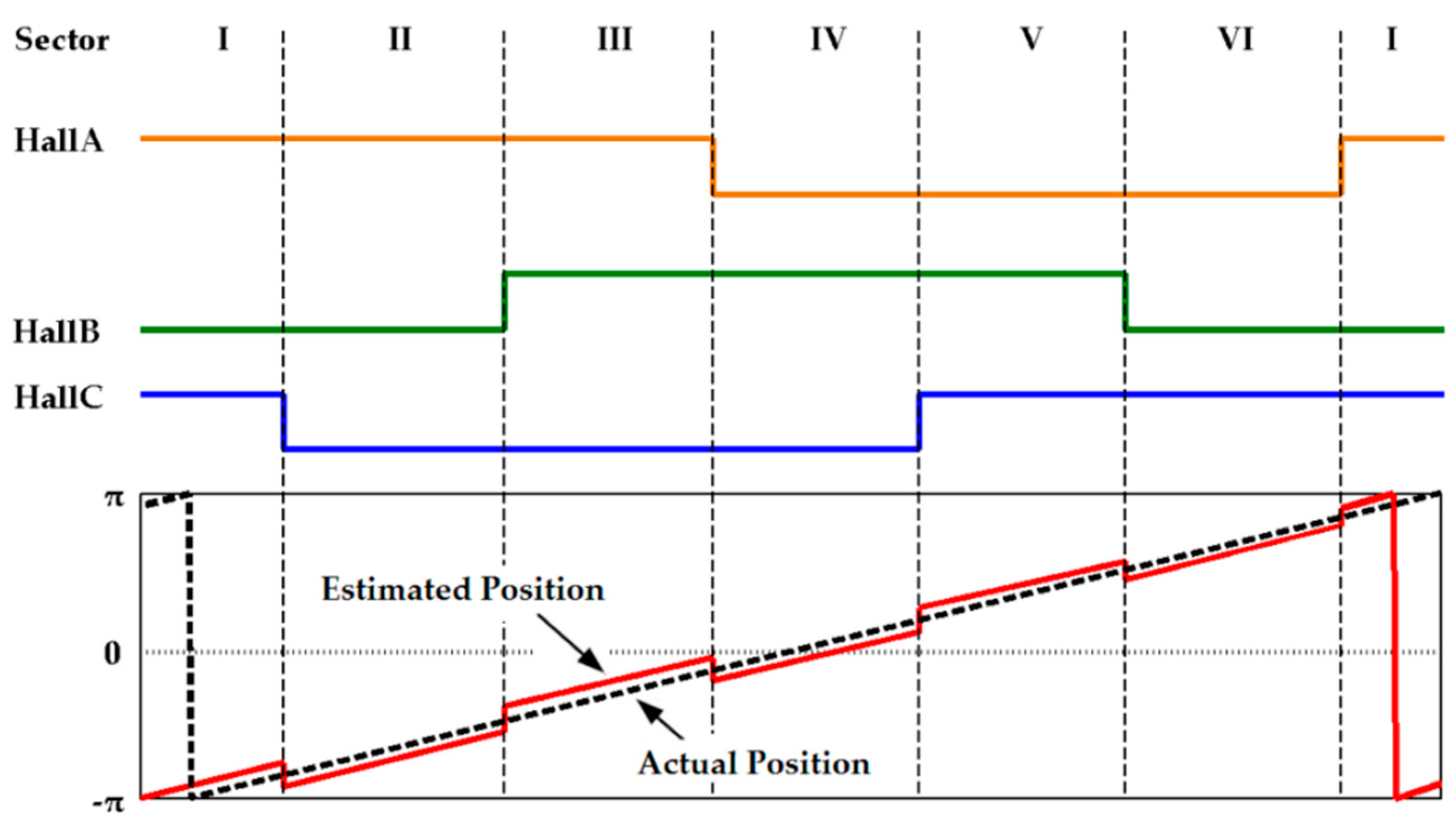
2.2. Rotor Position Estimation
2.2.1. Rotor Position Estimation Based on Average Motor Speed
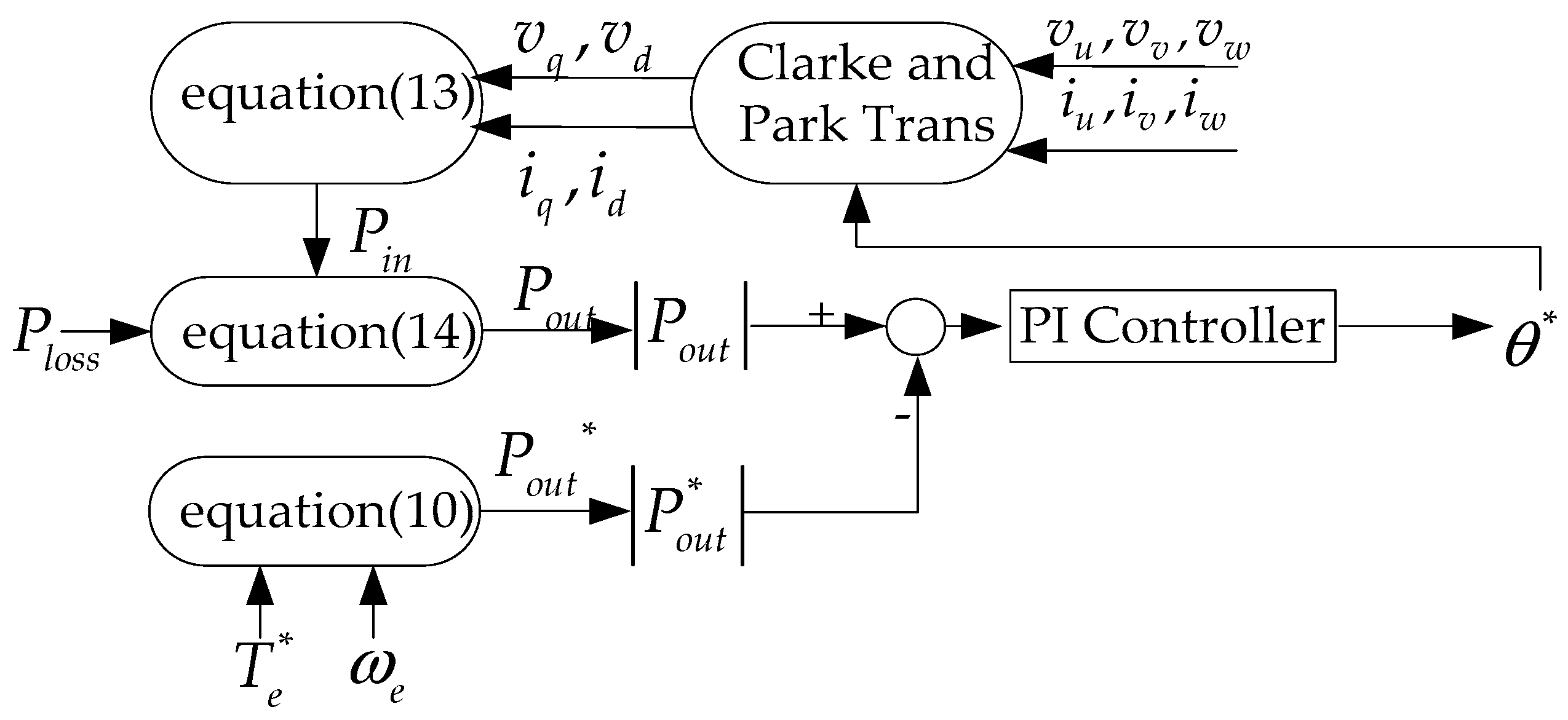
2.2.2. Rotor Position Estimation Based on the Power Closed-Loop Method
2.3. Permanent Magnetic Flux Linkage Estimation
3. Torque Control Strategy
3.1. Feedforward Parameter Iteration Method
- (1)
- Obtain the present motor parameters (the d-axis and q-axis inductances, stator resistance, and energy loss) from lookup tables;
- (2)
- Calculate one set of d-axis and q-axis current using control strategies;
- (3)
- Calculate the motor parameters with the current from step 2 using lookup tables;
- (4)
- Calculate another set of d-axis and q-axis current with the new set of motor parameters from step 3 using control strategies.
- (5)
- If the current error is within tolerance between the current and the previous step, the iteration is complete. Otherwise, return to step 2.
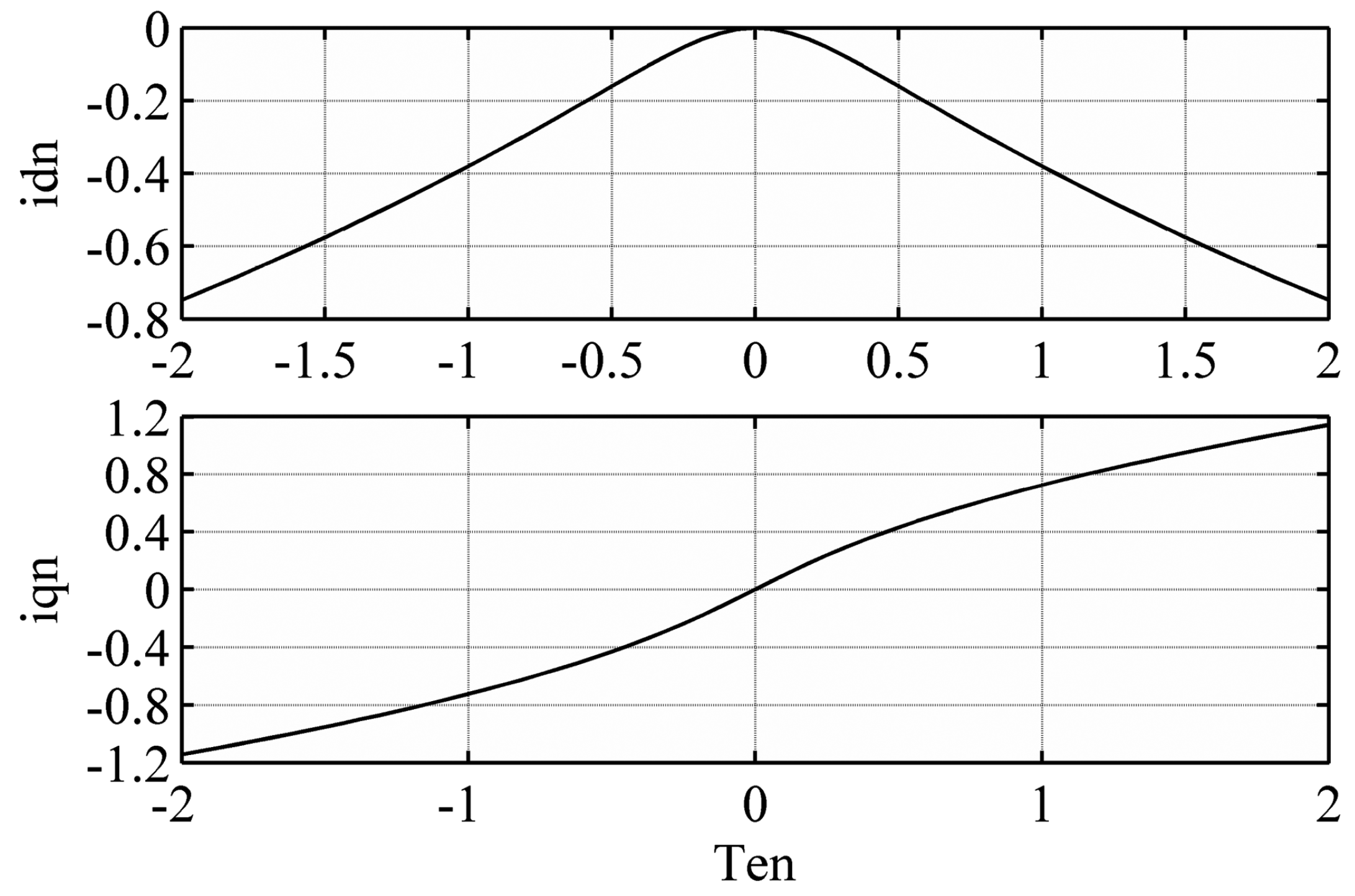
3.2. Maximum Torque Per Ampere Control Strategy
4. Simulation and Experimental Results
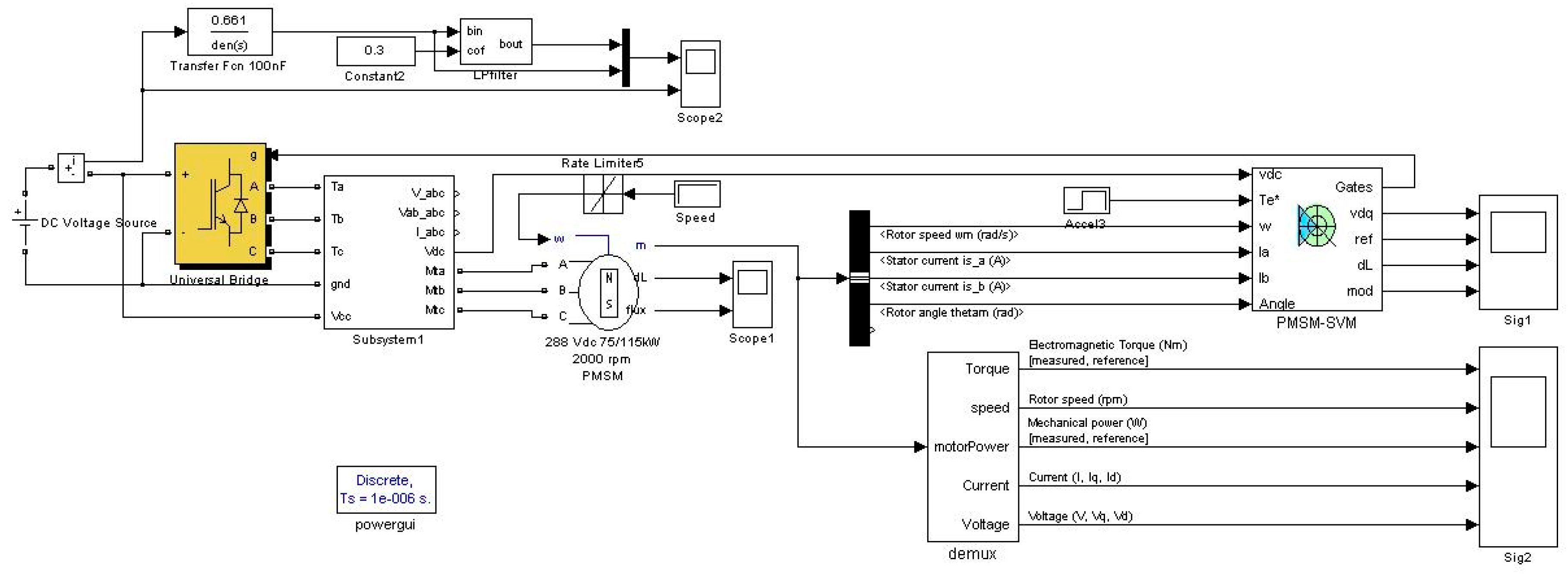
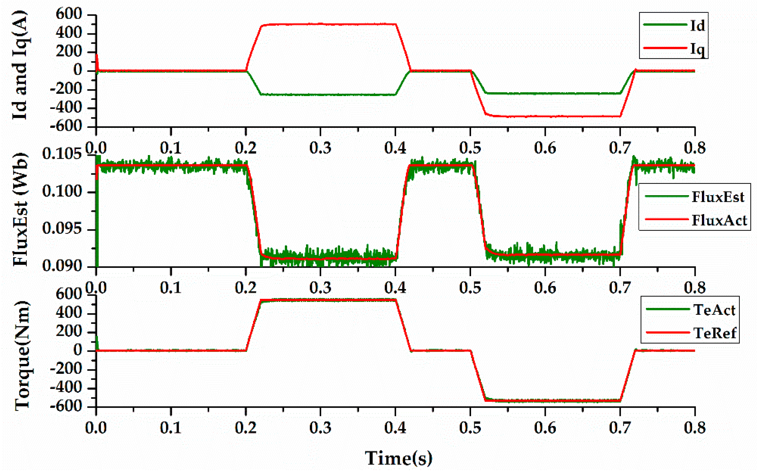
4.1. Simulation Results
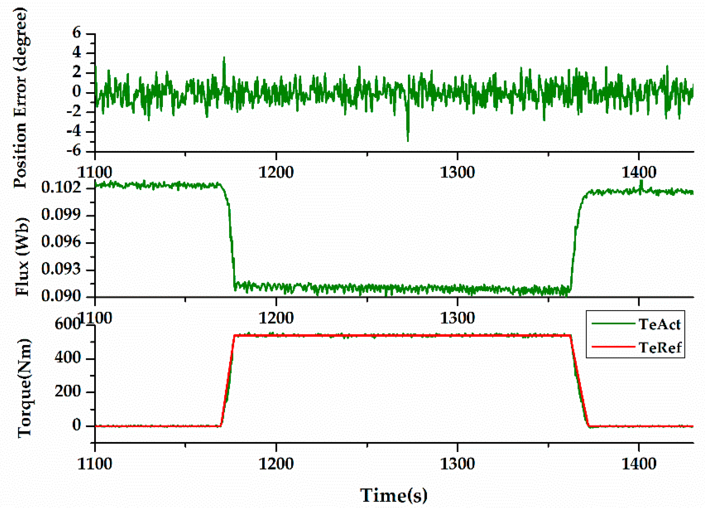
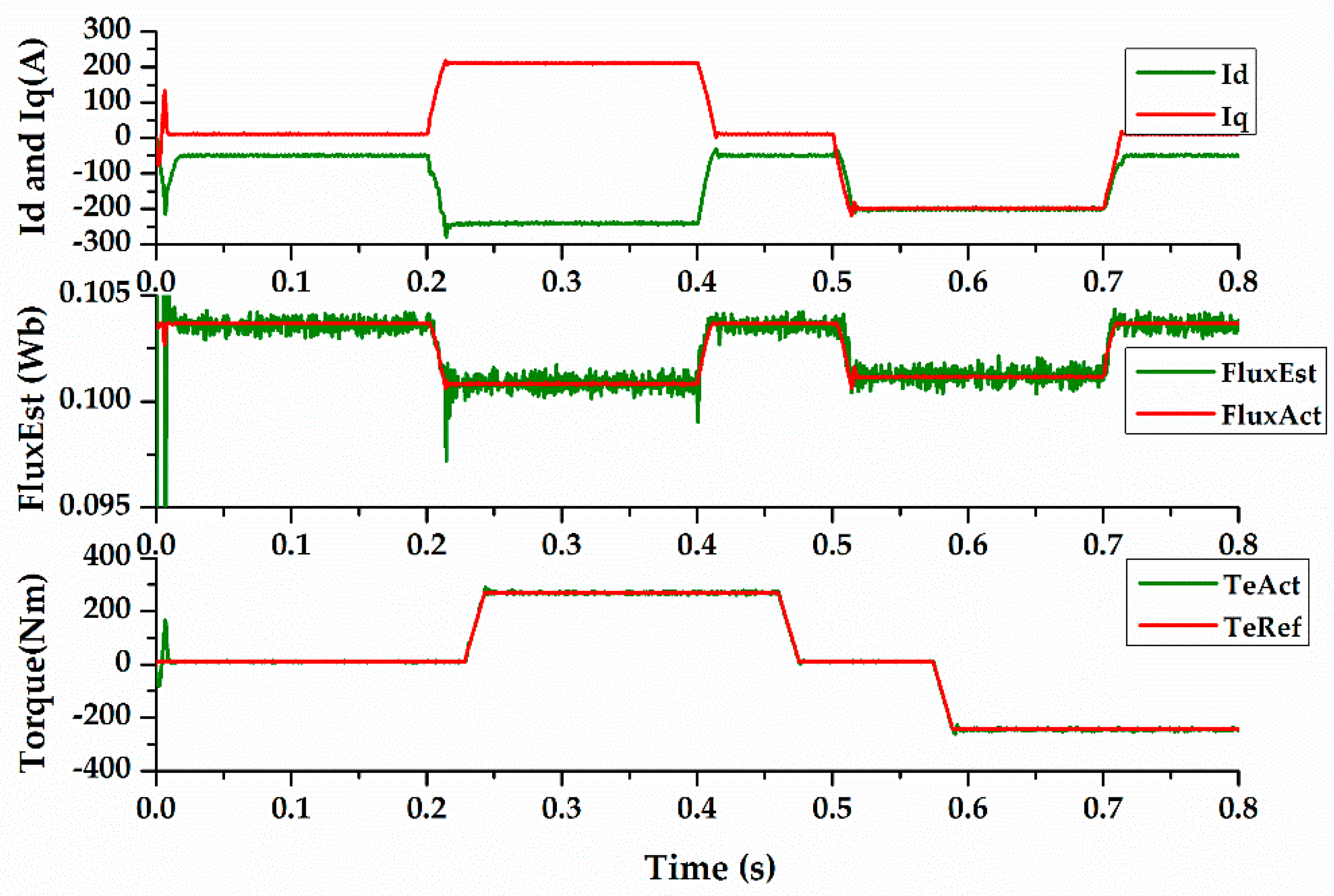
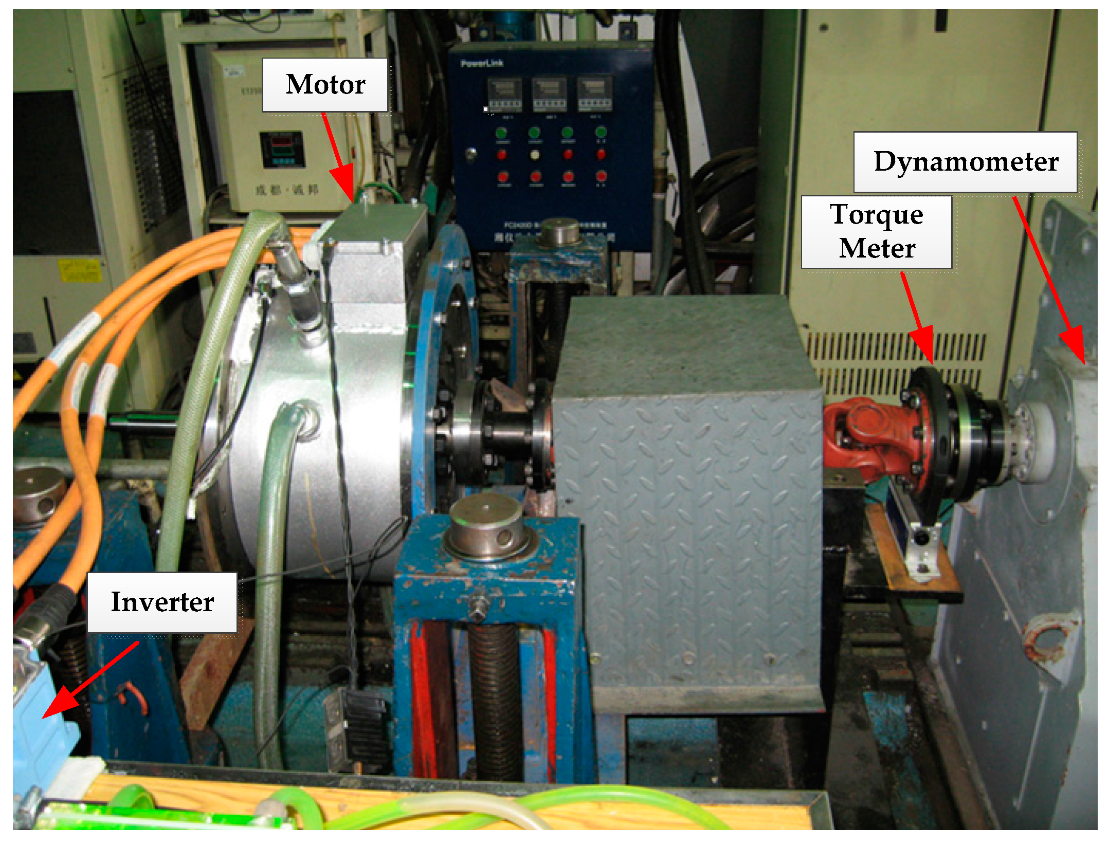
4.2. Experimental Results
5. Conclusions
Author Contributions
Conflicts of Interest
Nomenclature
| Input energy | |
| Output energy | |
| Energy loss | |
| Copper loss | |
| Iron loss | |
| Stray loss | |
| Mechanical loss | |
| Stator three phase voltages | |
| Stator d-axis and q-axis voltages | |
| Reference stator d-axis and q-axis voltages | |
| Stator three phase current | |
| Stator d-axis and q-axis current | |
| Reference stator d-axis and q-axis current | |
| d-axis and q-axis iron loss current | |
| Normalized stator d-axis and q-axis current | |
| Stator current | |
| d-axis field-weakening current | |
| Rotor electrical angular speed | |
| Electromagnetic torque | |
| Reference electromagnetic torque | |
| Normalized electromagnetic torque | |
| Actual rotor positon | |
| Estimated rotor positon | |
| d-axis and q-axis inductances | |
| d-axis and q-axis flux linkages | |
| Permanent magnetic flux linkage | |
| Estimated Permanent magnetic flux linkage | |
| Difference of d-axis and q-axis inductances | |
| Stator resistance | |
| Iron loss resistance | |
| Input power | |
| Output power | |
| Reference output power | |
| Power loss | |
| Copper power loss | |
| DC linkage voltage | |
| Control period | |
| Control frequency | |
| Time | |
| Number of pole pairs |
References
- Huang, W.; Zhang, Y.; Zhang, X.; Sun, G. Accurate torque control of interior permanent magnet synchronous machine. IEEE Tran. Energy Convers. 2014, 29, 29–37. [Google Scholar] [CrossRef]
- Rostami, A.; Asaei, B. A novel method for estimating the initial rotor position of pm motors without the position sensor. Energy Convers. Manag. 2009, 50, 1879–1883. [Google Scholar] [CrossRef]
- Dong-Bin, L.U.; Ouyang, M.G.; Jing, G.U.; Jian-Qiu, L.I. Field oriented control of permanent magnet brushless hub motor in electric vehicle. Electr. Mach. Control 2012, 11, 014. [Google Scholar]
- Kim, S.Y.; Choi, C.; Lee, K.; Lee, W. An improved rotor position estimation with vector-tracking observer in pmsm drives with low-resolution hall-effect sensors. IEEE Trans. Ind. Electron. 2011, 58, 4078–4086. [Google Scholar]
- Dalala, Z.M.; Cho, Y.; Lai, J.S. Enhanced Vector Tracking Observer for Rotor Position Estimation for PMSM Drives with Low Resolution Hall-Effect Position Sensors. In Proceedings of the 2013 IEEE International Electric Machines & Drives Conference (IEMDC), Chicago, IL, USA, 12–15 May 2013; pp. 484–491.
- Lidozzi, A.; Solero, L.; Crescimbini, F.; Napoli, A.D. SVM PMSM drive with low resolution hall-effect sensors. IEEE Tran. Power Electron. 2007, 22, 282–290. [Google Scholar] [CrossRef]
- Batzel, T.D.; Lee, K.Y. Slotless permanent magnet synchronous motor operation without a high resolution rotor angle sensor. IEEE Tran. Energy Convers. 2001, 15, 366–371. [Google Scholar] [CrossRef]
- Xu, B.; Mu, F.; Shi, G.; Ji, W.; Zhu, H. State estimation of permanent magnet synchronous motor using improved square root UKF. Energies 2016, 9, 489. [Google Scholar] [CrossRef]
- Jung, S.Y.; Nam, K. Pmsm control based on edge-field hall sensor signals through anf-pll processing. IEEE Trans. Ind. Electron. 2011, 58, 5121–5129. [Google Scholar] [CrossRef]
- Boileau, T.; Leboeuf, N.; Nahid-Mobarakeh, B.; Meibody-Tabar, F. Online identification of PMSM parameters: Parameter identifiability and estimator comparative study. IEEE Trans. Ind. Appl. 2011, 47, 1944–1957. [Google Scholar] [CrossRef]
- Liu, K.; Zhu, Z.Q.; Stone, D.A. Parameter estimation for condition monitoring of PMSM stator winding and rotor permanent magnets. IEEE Trans. Ind. Electron. 2013, 60, 5902–5913. [Google Scholar] [CrossRef]
- Horen, Y.; Strajnikov, P.; Kuperman, A. Simple mechanical parameters identification of induction machine using voltage sensor only. Energy Convers. Manag. 2015, 92, 60–66. [Google Scholar] [CrossRef]
- Park, J.W.; Koo, D.H.; Kim, J.M.; Kim, H.G. Improvement of control characteristics of interior permanent magnet synchronous motor for electric vehicle. IEEE Trans. Ind. Appl. 2001, 37, 1754–1760. [Google Scholar] [CrossRef]
- Meessen, K.J.; Thelin, P.; Soulard, J.; Lomonova, E.A. Inductance calculations of permanent-magnet synchronous machines including flux change and self- and cross-saturations. IEEE Trans. Magn. 2008, 44, 2324–2331. [Google Scholar] [CrossRef]
- Liang, P.; Pei, Y.; Chai, F.; Zhao, K. Analytical calculation of d- and q-axis inductance for interior permanent magnet motors based on winding function theory. Energies 2016, 9, 580. [Google Scholar] [CrossRef]
- Mohamed, Y.R.; Lee, T.K. Adaptive self-tuning MTPA vector controller for IPMSM drive system. IEEE Tran. Energy Convers. 2006, 21, 636–644. [Google Scholar] [CrossRef]
- Urasaki, N.; Senjyu, T.; Uezato, K. An accurate modeling for permanent magnet synchronous motor drives. In Proceedings of the APEC Fifteenth IEEE Applied Power Electronics Conference and Exposition, New Orleans, LA, USA, 6–10 February 2000; Volume 381, pp. 387–392.
- Huang, W.Q.; Zhang, Y.T.; Zhang, X.C. Research on power closed-loop torque control strategy of PMSM in HEV application. Trans. Beijing Inst. Technol. 2015, 35, 246–250. [Google Scholar]
- Kwon, Y.C.; Kim, S.; Sul, S.K. Voltage feedback current control scheme for improved transient performance of permanent magnet synchronous machine drives. IEEE Trans. Ind. Electron. 2012, 59, 3373–3382. [Google Scholar] [CrossRef]
- Choi, J.W.; Sul, S.K. Inverter output voltage synthesis using novel dead time compensation. IEEE Trans. Power Electron. 1996, 11, 221–227. [Google Scholar] [CrossRef]
- Choi, J.W.; Sul, S.K. A new compensation strategy reducing voltage/current distortion in PWM VSI systems operating with low output voltages. IEEE Trans. Ind. Appl. 1995, 31, 1001–1008. [Google Scholar] [CrossRef]
- Cheng, B.; Tesch, T.R. Torque feedforward control technique for permanent-magnet synchronous motors. IEEE Trans. Ind. Electron. 2010, 57, 969–974. [Google Scholar] [CrossRef]
- Morimoto, S.; Sanada, M.; Takeda, Y. Wide-speed operation of interior permanent magnet synchronous motors with high-performance current regulator. IEEE Trans. Ind. Appl. 1994, 30, 920–926. [Google Scholar] [CrossRef]
- Kim, J.M.; Sul, S.K. Speed control of interior permanent magnet synchronous motor drive for the flux weakening operation. IEEE Trans. Ind. Appl. 1995, 2000, 103–108. [Google Scholar]


| Parameter | Symbol | Value |
|---|---|---|
| Number of pole pairs | p | 6 |
| Stator resistance | Rs | 4.23 mΩ |
| Magnet flux linkage | ϕf | 0.1039 Wb |
| d-axis inductance | Ld | 0.171 mH |
| q-axis inductance | Lq | 0.391 mH |
| DC linkage voltage | Vdc | 288 V |
| Maximum speed | nb | 4000 Rpm |
| Peak current | Ipk | 570 Apk |
| Rated power | Pr | 75 kW |
| Peak torque | Tmax | 540 Nm |
| Coefficient of RSac to RsDC | μ | 0.1 |
| Hysteresis current coefficient | Kh | 0.6637 |
| Eddy current coefficient | Ke | 0.00084 |
| Stray loss coefficient | cStr | 2.56 × 10⁻⁹ |
| Mechanical friction torque | Tfric | 5.24 |
| Windage torque coefficient | cwind | 3.35 × 10⁻³ |
© 2017 by the authors. Licensee MDPI, Basel, Switzerland. This article is an open access article distributed under the terms and conditions of the Creative Commons Attribution (CC BY) license ( http://creativecommons.org/licenses/by/4.0/).
Share and Cite
Yu, L.; Zhang, Y.; Huang, W. Accurate and Efficient Torque Control of an Interior Permanent Magnet Synchronous Motor in Electric Vehicles Based on Hall-Effect Sensors. Energies 2017, 10, 410. https://doi.org/10.3390/en10030410
Yu L, Zhang Y, Huang W. Accurate and Efficient Torque Control of an Interior Permanent Magnet Synchronous Motor in Electric Vehicles Based on Hall-Effect Sensors. Energies. 2017; 10(3):410. https://doi.org/10.3390/en10030410
Chicago/Turabian StyleYu, Lei, Youtong Zhang, and Wenqing Huang. 2017. "Accurate and Efficient Torque Control of an Interior Permanent Magnet Synchronous Motor in Electric Vehicles Based on Hall-Effect Sensors" Energies 10, no. 3: 410. https://doi.org/10.3390/en10030410
APA StyleYu, L., Zhang, Y., & Huang, W. (2017). Accurate and Efficient Torque Control of an Interior Permanent Magnet Synchronous Motor in Electric Vehicles Based on Hall-Effect Sensors. Energies, 10(3), 410. https://doi.org/10.3390/en10030410