
Thermoeconomic Evaluation of Modular Organic Rankine Cycles for Waste Heat Recovery over a Broad Range of Heat Source Temperatures and Capacities


Abstract
:1. Introduction
- Which chemical class of ORC working fluids can be applied in a wide range of heat source temperatures?
- Which ORC design is favorable to cover also a broad range of heat source thermal capacities?
- Which aspects must be included in a thermoeconomic model to allow for a robust and holistic evaluation of modular ORC units?
- For which range of heat source temperatures and thermal capacities are ORC units economically feasible?
2. Theory
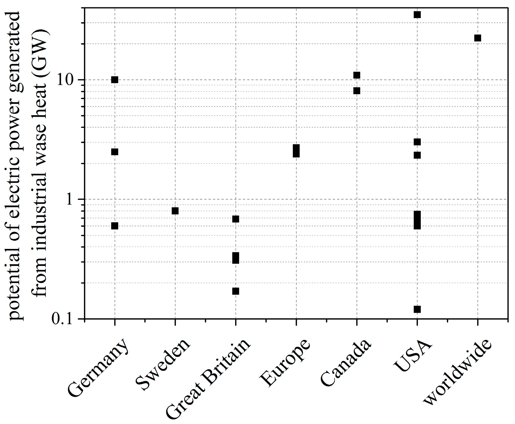
2.1. Industrial Waste Heat
- The values for the electric power potential from waste heat recovery differ significantly, however, it is a common fact that a huge potential is available.
- The thermal capacity of industrial waste heat flows strongly depends on application ranging from a few kW up to several MW.
- Industrial waste heat covers a broad range of heat source temperature, however, 300 °C and 600 °C seems to be a promising range for electricity generation from waste heat [25].
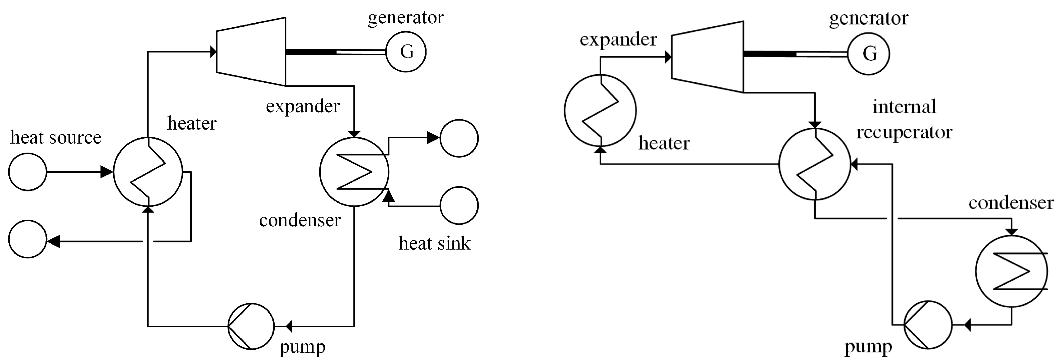
2.2. Organic Raninke Cycle
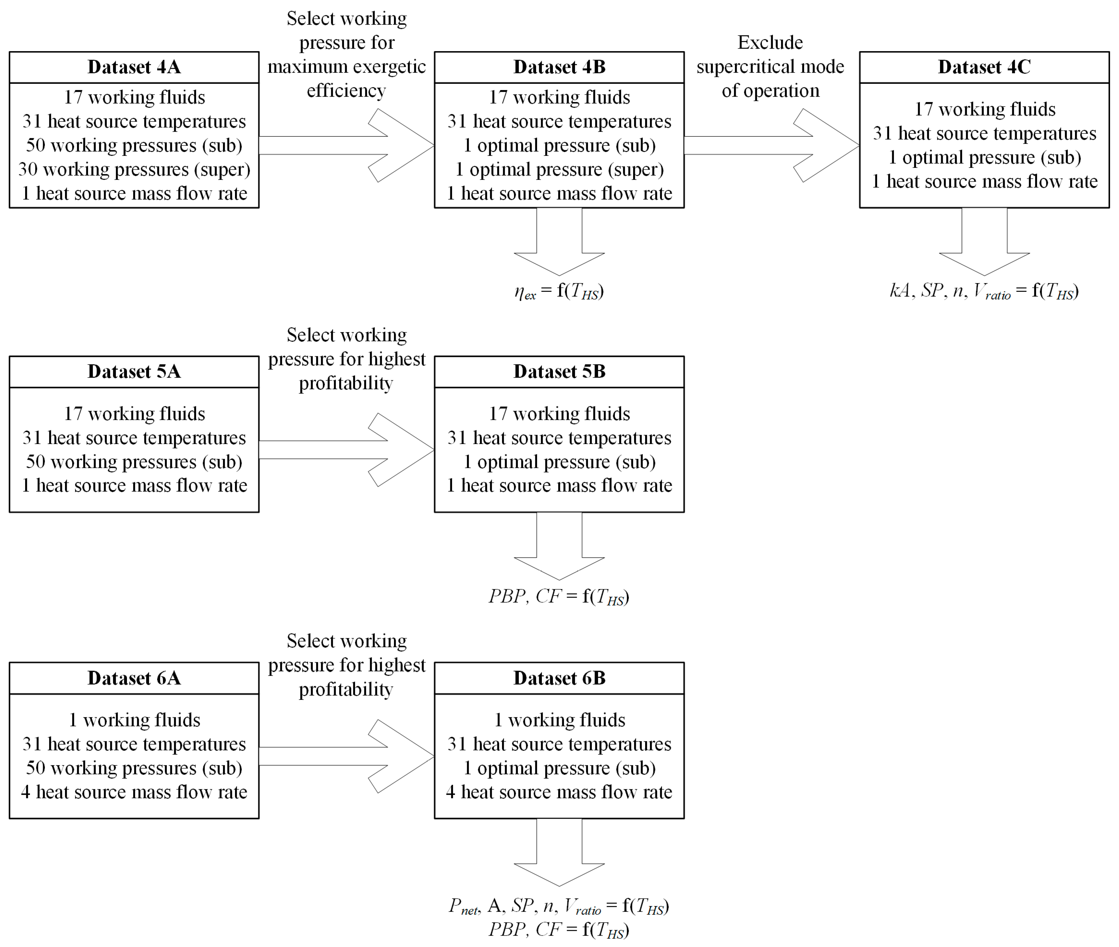
3. Methodology
3.1. Approach for Modular Design of ORC Units
3.2. Selection of Working Fluids
3.3. Boundary Conditions
3.4. Thermodynamic and Constructional Evaluation Parameters
3.5. Overall Flow Chart
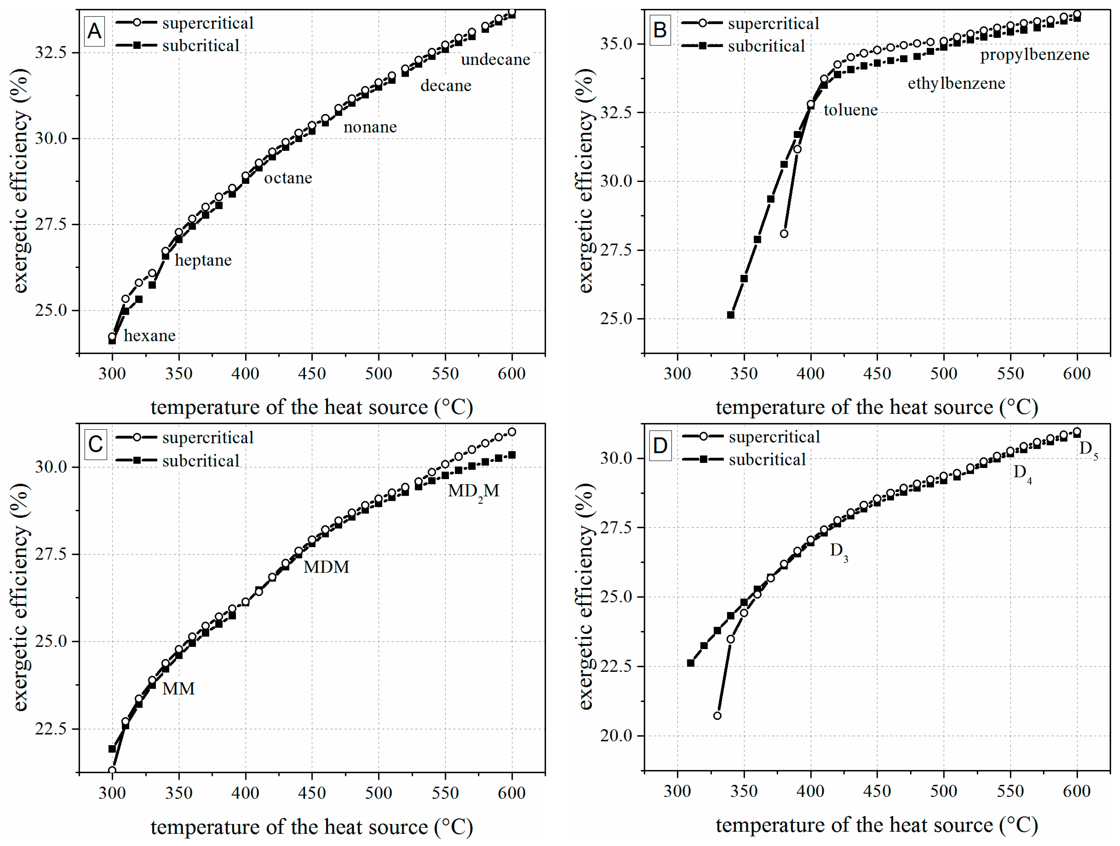
4. Thermodynamic and Constructional Evaluation
4.1. Thermodynamic Results
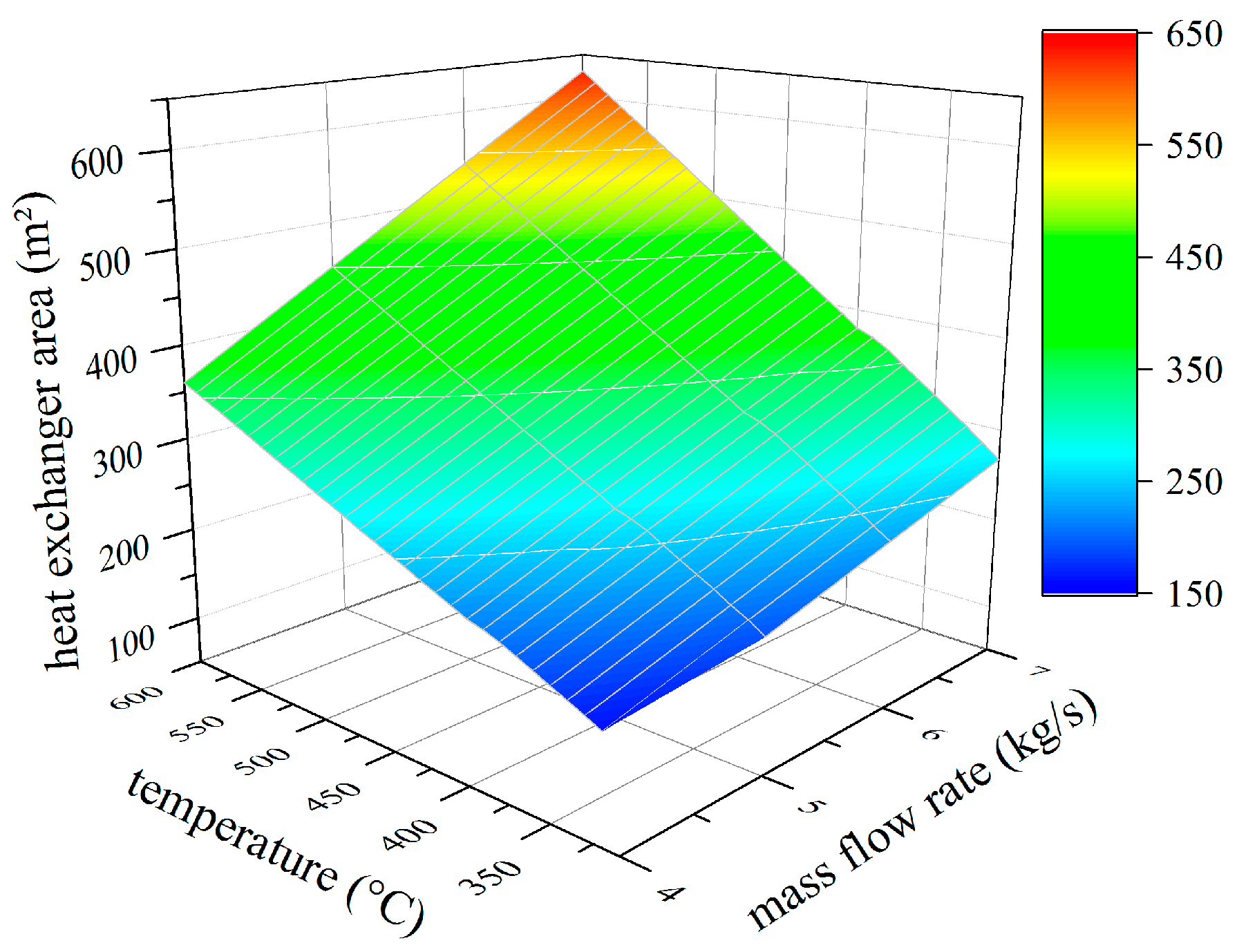
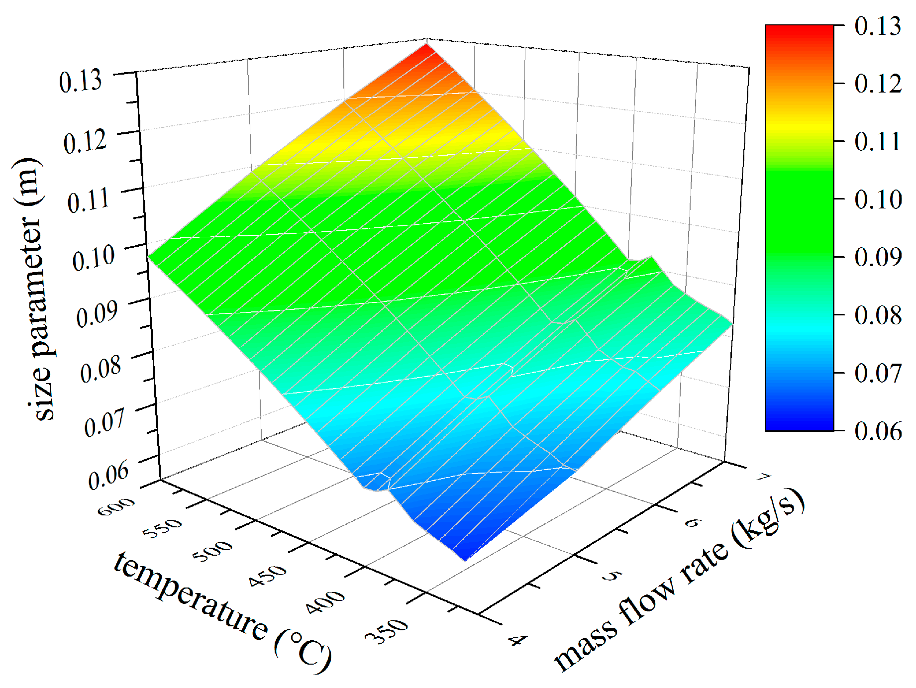
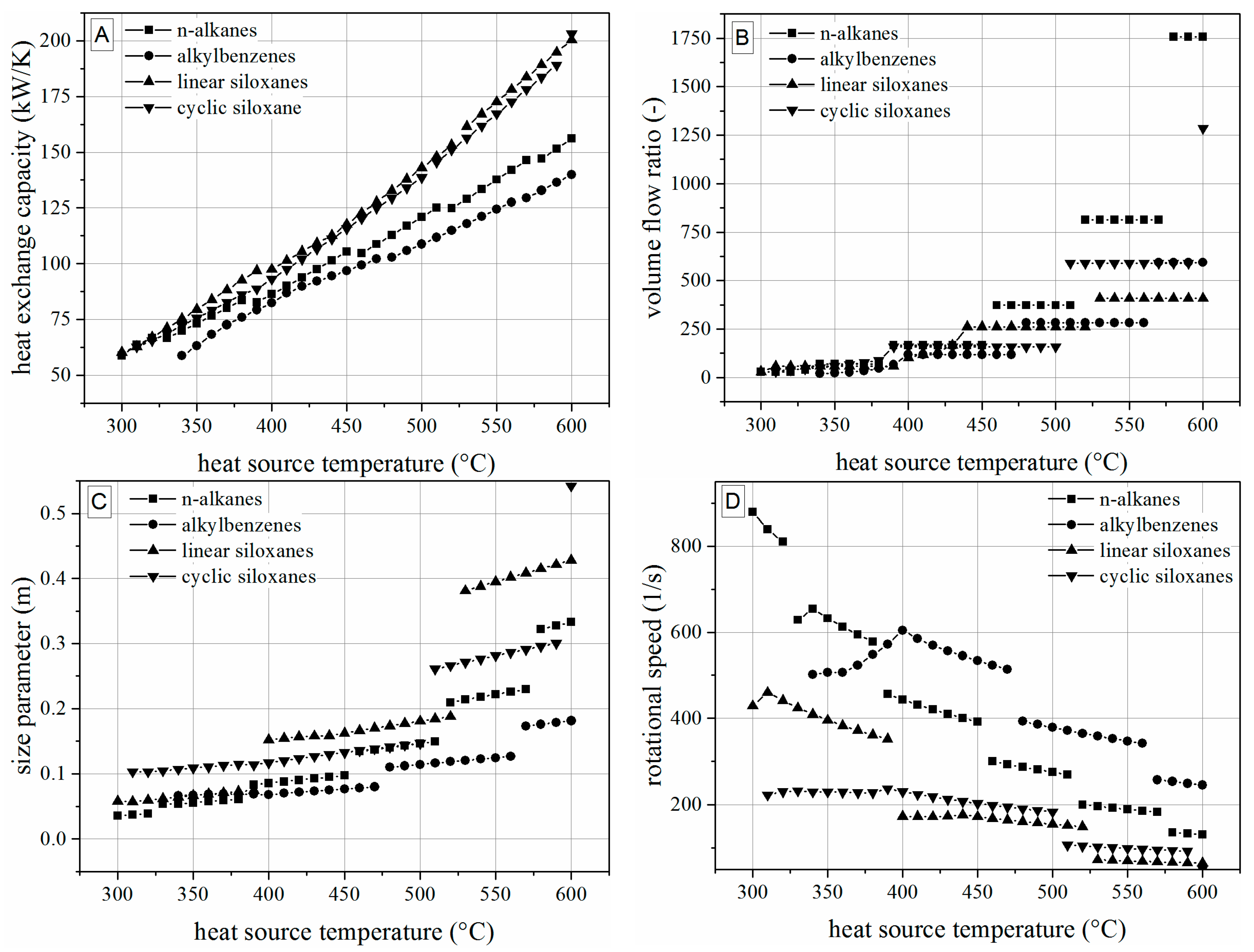
4.2. Analysis of Constructional Parameters
- Alkylbenzenes are favorable working fluids concerning exergetic efficiency, dimension of the turbine (SP) and heat exchanger (kA).
- Linear siloxanes have significant advantages concerning the complexity of the turbine due to low rotational speed.
- n-Alkanes combine the disadvantages of both formerly mentioned chemical classes.
- None of the chemical classes outperforms in all relevant parameters.
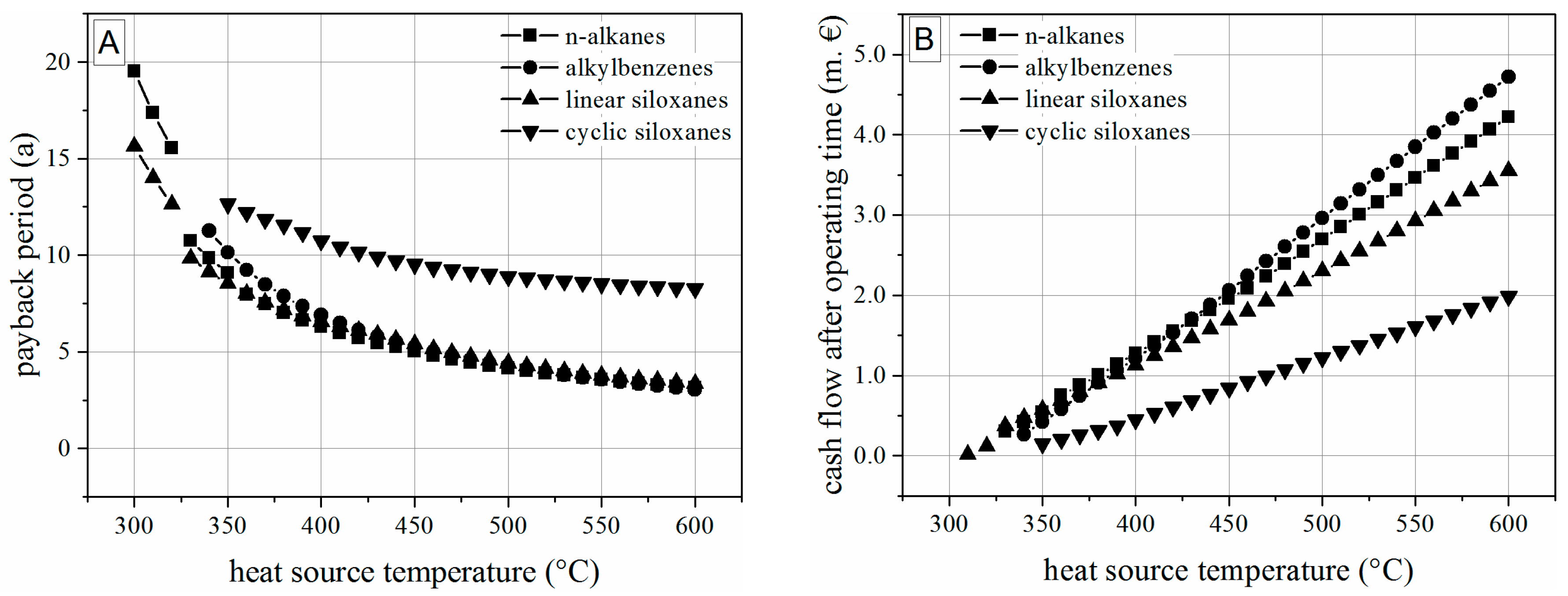
5. Thermoeconomic Evaluation
5.1. Thermoeconomic Modeling
5.1.1. Heat Exchanger
5.1.2. Pump
5.1.3. Turbine
5.1.4. Piping
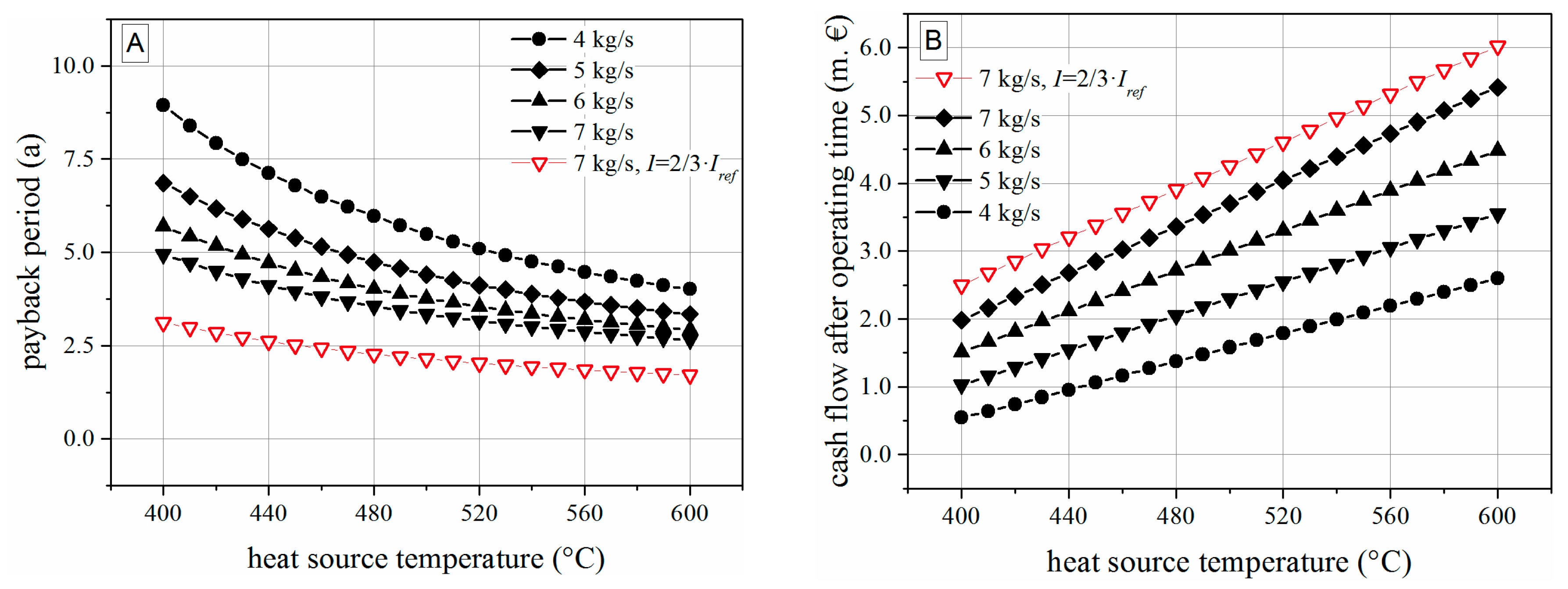
5.2. Thermoeconomic Results
6. Modularly-Designed ORC
7. Conclusions
- Taking into account thermodynamic, construction and economic parameters, linear siloxanes and within this group, the working fluid hexamethyldisiloxane is a promising candidate for waste heat recovery in a broad range of heat source temperatures and capacities.
- A concept with direct contact evaporator, internal recuperator, and expansion by a turbine is a favorable design for modularly-based ORC units.
- A holistic thermoeconomic approach has to be based on scaling and complexity parameters. Especially for the turbine, the typically used exponential cost estimation method is not appropriate as technology leaps can occur depending on the working pressure.
- For the boundary conditions and turbine model within this study, a modular concept based on hexamethyldisiloxane, a temperature range of 400 to 600 °C and a mass flow rate exceeding 4 kg/s can be recommended.
Acknowledgments
Author Contributions
Conflicts of Interest
Nomenclature
| Abbreviations | ||
| a | year | |
| CF | Cash flow | |
| D3 | hexamethylcyclotrisiloxane | |
| D4 | octamethylcyclotetrasiloxane | |
| D5 | decamethylcyclopentasiloxane | |
| MD2M | decamethyltetrasiloxane | |
| MDM | octamethyltrisiloxane | |
| MM | hexamethyldisiloxane | |
| O | oxygen | |
| ORC | Organic Rankine Cycle | |
| P | plant | |
| PBP | payback period | |
| PR-BM | Peng-Robinson Boston-Mathias | |
| Ref | reference plant | |
| Si | silicium | |
| STHE | shell-and-tube heat exchanger | |
| sub | subcritical | |
| super | supercritical | |
| Subscripts | ||
| 0 | dead state | |
| c | countercurrent | |
| crit | critical | |
| ex | exergetic | |
| g | gaseous | |
| HS | heat source | |
| i | component i | |
| is | isentropic | |
| l | liquid | |
| max | maximum | |
| p | pump | |
| r | reduced | |
| s | specific | |
| s | saturation | |
| t | turbine | |
| TGU | turbine-generator-unit | |
| Symbols | Unit | |
| T | temperature | °C, K |
| A | heat exchanger area | m² |
| C | capacity | W, m² |
| D | diameter | m |
| F | correction factor | - |
| h | specific enthalpy | kJ/kg |
| I | investment costs | € |
| kA | heat exchanger capacity | W/m² |
| L | length | m |
| LMTD | logarithmic mean temperature difference | K |
| M | exponential factor | - |
| M | molar mass | g/mol |
| mass flow rate | kg/s | |
| n | rotational speed | 1/s |
| NTU | number of transfer units | - |
| Nu | Nusselt number | - |
| Pr | Prandl number | - |
| heat flux | W | |
| R | density ratio | - |
| Re | Reynolds number | - |
| s | specific entropy | kJ/kgK |
| SP | size parameter | M |
| volume flow rate | m³/s | |
| x | vapor fraction | - |
| Greek symbols | ||
| η | efficiency | |
| ζ | pipe friction factor | |
Appendix A. Physico-Chemical Properties of Evaluated Working Fluids

| Name | Abbreviation | M | Ts (1 bar) | ps (85 °C) | Tcrit | pcrit |
|---|---|---|---|---|---|---|
| g/mol | K | bar | K | bar | ||
| n-pentane | 72.15 | 309.22 | 4.16 | 469.70 | 33.70 | |
| n-hexane | 86.18 | 341.88 | 1.63 | 507.60 | 30.25 | |
| n-heptane | 100.20 | 371.58 | 0.67 | 540.20 | 27.40 | |
| n-octane | 114.23 | 398.83 | 0.28 | 568.70 | 24.90 | |
| n-nonane | 128.26 | 423.97 | 0.12 | 594.60 | 22.90 | |
| n-decane | 142.28 | 447.30 | 0.05 | 617.70 | 21.10 | |
| n-undecane | 156.31 | 469.08 | 0.02 | 639.00 | 19.50 | |
| n-dodecane | 170.34 | 489.48 | 0.01 | 658.00 | 18.20 | |
| methylbenzene | toluene | 92.14 | 383.78 | 0.46 | 591.75 | 41.08 |
| ethylbenzene | 106.17 | 409.35 | 0.20 | 617.15 | 36.09 | |
| n-propylbenzene | 120.19 | 432.39 | 0.10 | 638.35 | 32.00 | |
| hexamethyldisiloxane | MM | 162.38 | 373.67 | 0.63 | 518.70 | 19.14 |
| octamethyltrisiloxane | MDM | 236.53 | 425.70 | 0.12 | 564.40 | 14.40 |
| decamethyltetrasiloxane | MD2M | 310.69 | 467.50 | 0.02 | 599.40 | 12.27 |
| hexamethylcyclotrisiloxane | D3 | 222.46 | 408.26 | 0.21 | 554.20 | 16.63 |
| octamethylcyclotetrasiloxane | D4 | 296.62 | 448.15 | 0.05 | 586.50 | 13.32 |
| decamethylcyclopentasiloxane | D5 | 307.77 | 484.10 | 0.01 | 619.15 | 11.60 |
Appendix B. Boundary Conditions for Economic Evaluation
| Parameter | Value | Unit | Reference |
|---|---|---|---|
| operational life time | 20 | a | |
| full load hours | 8000 | h/a | |
| price of electricity | 12.88 | €-Cent/kWh | [98] |
| ancillary costs | 35 | % of invest | [28] |
| specific cost of cooling | 0.1288 | €-Cent/kWhth | [28,99,100] |
| specific cost of maintenance | 2.0 | % of invest per year | [99] |
| specific cost of insurance | 2.0 | % of invest per year | [101] |
| specific cost of process integration | 20 | % of invest | [101] |
| specific cost of personnel | 40 | €/h | |
| working hours of personnel | 260 | h/year | [75] |
| inflation electricity | 4.0 | % | |
| inflation general | 2.0 | % | |
| tax rate | 28.8 | % | |
| interest rate | 4.0 | % | |
| share of loan capital | 100 | % | |
| redemption time | 20 | a | |
| redemption rate | 5.0 | % |
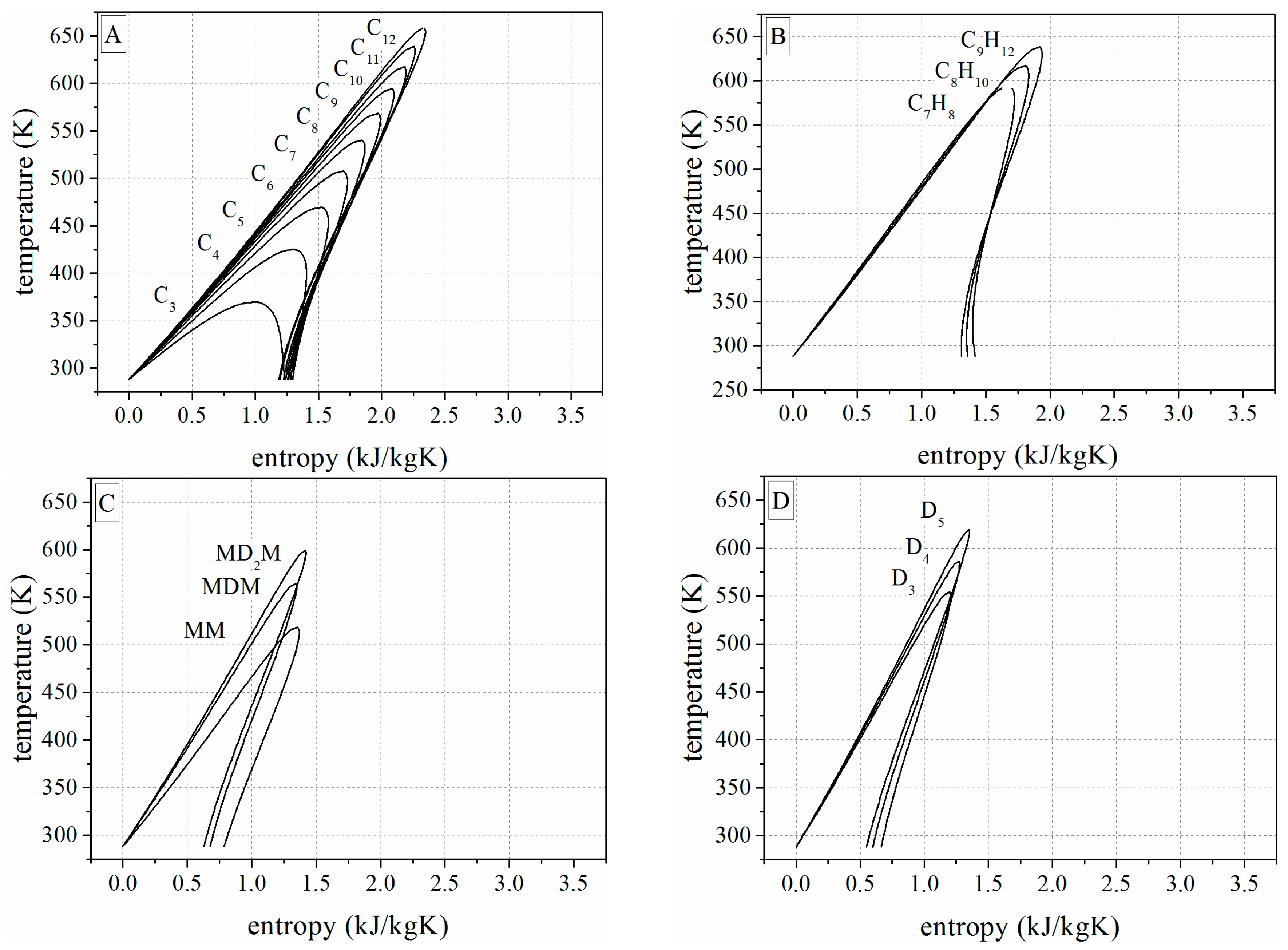
Appendix C. Temperature-Entropy-Diagrams of the Investigated Working Fluids

References
- European Union. Directive 2006/32/EC of the European Parliament and the Council on Energy End-Use Efficiency and Energy Services and Repealing Council Directive 93/76/EEC; European Union: Brussels, Belgium, 2006. [Google Scholar]
- Lai, N.A.; Wendland, M.; Fischer, J. Working fluids for high-temperature organic Rankine cycles. Energy 2011, 36, 199–211. [Google Scholar] [CrossRef]
- Drescher, U.; Brüggemann, D. Fluid selection for the Organic Rankine Cycle (ORC) in biomass power and heat plants. Appl. Therm. Eng. 2007, 27, 223–228. [Google Scholar] [CrossRef]
- Saleh, B.; Koglbauer, G.; Wendland, M.; Fischer, J. Working fluids for low-temperature Organic Rankine Cycles. Energy 2007, 32, 1210–1221. [Google Scholar] [CrossRef]
- Bao, J.; Zhao, L. A review of working fluid and expander selections for Organic Rankine Cycle. Renew. Sustain. Energy Rev. 2013, 24, 325–342. [Google Scholar] [CrossRef]
- Linke, P.; Papadopoulos, A.; Seferlis, P. Systematic Methods for Working Fluid Selection and the Design, Integration and Control of Organic Rankine Cycles—A Review. Energies 2015, 8, 4755–4801. [Google Scholar] [CrossRef]
- Schwöbel, J.A.H.; Preißinger, M.; Brüggemann, D.; Klamt, A. High-Throughput-Screening of Working Fluids for the Organic Rankine Cycle (ORC) based on COSMO-RS and Thermodynamic Process Simulations. Ind. Eng. Chem. Res. 2016. [Google Scholar] [CrossRef]
- Preißinger, M.; Schwöbel, J.; Klamt, A.; Brüggemann, D. High-Throughput Screening of ORC Fluids for Mobile Applications. In Energy and Thermal Management, Air Conditioning, Waste Heat Recovery; Junior, C., Jänsch, D., Dingel, O., Eds.; Springer International Publishing: Cham, Switzerland, 2017; pp. 35–40. [Google Scholar]
- Preißinger, M.; Schatz, S.; Vogl, A.; König-Haagen, A.; Brüggemann, D. Thermoeconomic analysis of configuration methods for modular Organic Rankine Cycle units in low-temperature applications. Energy Convers. Manag. 2016, 127, 25–34. [Google Scholar] [CrossRef]
- Williams, R., Jr. “Six-Tenths Factor” Aids in Approximating Costs. Chem. Eng. 1947, 12, 124–125. [Google Scholar]
- Chilton, C. Six Tenths Factor applies to complete plant costs. Chem. Eng. 1950, 57, 112–114. [Google Scholar]
- Lecompte, S.; Huisseune, H.; van den Broek, M.; Vanslambrouck, B.; de Paepe, M. Review of Organic Rankine Cycle (ORC) architectures for waste heat recovery. Renew. Sustain. Energy Rev. 2015, 47, 448–461. [Google Scholar] [CrossRef]
- Colonna, P.; Casati, E.; Trapp, C.; Mathijssen, T.; Larjola, J.; Turunen-Saaresti, T.; Uusitalo, A. Organic Rankine Cycle Power Systems: From the Concept to Current Technology, Applications, and an Outlook to the Future. J. Eng. Gas Turbines Power 2015, 137, 100801–100819. [Google Scholar] [CrossRef]
- Sollesnes, G.; Helgerud, H.E. Utnyttekse av Spillvarme fra Norsk Industri—En Potensialstudie; Enova: Trondheim, Norway, 2009. (In Norwegian) [Google Scholar]
- Pehnt, M.; Bödeker, J.; Arens, M.; Jochem, E. Die Nutzung Industrieller Abwärme—Technisch-Wirtschaftliche Potenziale und Energiepolitische Umsetzung. Ifeu: Heidelberg, Germany, 2010. Available online: http://www.isi.fraunhofer.de/isi-wAssets/docs/e/de/publikationen/Nutzung_industrieller_Abwaerme.pdf (accessed on 20 December 2016). (In German)
- iZES gGmbH. Erschließung von Minderungspotenzialen Spezifischer Akteure, Instrumente und Technologien zur Erreichung der Klimaschutzziele im Rahmen der Nationalen Klimaschutzinitiative (EMSAITEK), Endbericht zu PART III Beitrag von Mini-KWK-Anlagen zur Zielerreichung der Nationalen Klimaschutzinitiative. Available online: www.izes.de/cms/upload/publikationen/EM_9_40_Teil_3.pdf (accessed on 17 July 2013).
- Hamm, H.; Noeres, P.; Oser, E. Potenziale zur Nutzung von Abwärme für die Stromerzeugung. Euroheat Power 2008, 37, 36–43. [Google Scholar]
- Berger, H.; Hoenig, V. Energieeffizienz der Österreichischen Zementindustrie; Vereinigung der Österreichischen Zementindustrie: Vienna, Austria, 2010. [Google Scholar]
- Bailey, O.; Worrell, E. Clean Energy Technologies: A Preliminary Inventory of the Potential for Electricity Generation; University of California: Berkeley, CA, USA, 2005. [Google Scholar]
- Galanis, N.; Cayer, E.; Roy, P.; Denis, E.; Désilets, M. Electricity Generation from Low Temperature Sources. J. Appl. Fluid Mech. 2009, 2, 55–67. [Google Scholar]
- Zhang, L. Waste Heat Recovery from Metal Industries. JOM 2012, 64, 982–984. [Google Scholar] [CrossRef]
- U.S. Department of Energy. Waste Heat Recovery: Technology and Opportunities in U.S. Industry; U.S. Department of Energy: Washington, DC, USA, 2008.
- McKenna, R.; Norman, J. Spatial modelling of industrial heat loads and recovery potentials in the UK. Energy Policy 2010, 38, 5878–5891. [Google Scholar] [CrossRef]
- Campana, F.; Bianchi, M.; Branchini, L.; de Pascale, A.; Peretto, A.; Baresi, M.; Fermi, A.; Rossetti, N.; Vescovo, R. ORC waste heat recovery in European energy intensive industries: Energy and GHG savings. Energy Convers. Manag. 2013, 76, 244–252. [Google Scholar] [CrossRef]
- Schroeder, D.J. Organic Rankine Cycle Working Fluid Considerations for Waste Heat to Power Applications. ASHRAE Trans. 2010, 116, 525–533. [Google Scholar]
- Obernberger, I.; Thornhofer, P.; Reisenhofer, E. Description and evaluation of the new 1000 kWel organic Rankine cycle process integrated in the biomass CHP plant in Lienz, Austria. Euroheat Power 2002, 10, 18–25. [Google Scholar]
- Obernberger, I. Decentralized biomass combustion: State of the art and future development: Paper to the keynote lecture of the session “Processes for decentralized heat and power production based on cumbustion” at the 9th European Bioenergy Conference, June 1996, Copenhagen, Denmark. Biomass Bioenergy 1998, 14, 33–56. [Google Scholar]
- Baatz, E.; Heidt, G. First waste heat power generating plant using the Organic Rankine Cycle Process for utilizing residual clinker cooler exhaust air: Erstes Abwärmekraftwerk nach dem Organic-Rankine-Cycle-Verfahren für die Restnutzung der Klinkerkühlerabluft. Int. Cem.-Lime-Gypsum 2000, 8, 425–436. [Google Scholar]
- Schuster, A.; Karellas, S.; Kakaras, E.; Spliethoff, H. Energetic and economic investigation of Organic Rankine Cycle applications. Appl. Therm. Eng. 2009, 29, 1809–1817. [Google Scholar] [CrossRef]
- Lemort, V.; Quoilin, S.; Cuevas, C.; Lebrun, J. Testing and modeling a scroll expander integrated into an Organic Rankine Cycle. Appl. Therm. Eng. 2009, 29, 3094–3102. [Google Scholar] [CrossRef]
- Quoilin, S.; Lemort, V.; Lebrun, J. Experimental study and modeling of an Organic Rankine Cycle using scroll expander. Appl. Energy 2010, 87, 1260–1268. [Google Scholar] [CrossRef]
- Leibowitz, H.; Smith, I.K.; Stosic, N. Cost Effective Small Scale ORC Systems for Power Recovery from Low Grade Heat Sources. In Proceedings of the ASME Advanced Energy Systems Division—2006, Chicago, IL, USA, 5–10 November 2006.
- Smith, I.K.; Stosic, N.; Kovacevic, A. Screw expanders increase output and decrease the cost of geothermal binary power plant systems. In Proceedings of the Geothermal Resources Council Annual Meeting 2005: Geothermal Energy—The World’s Buried Treasure, Reno, NV, USA, 25–28 September 2005.
- Brasz, J.; Biederman, B. Power Generation with a Centrifugal Compressor. U.S. Patent WO/2004/043607, 12 December 2004. [Google Scholar]
- Brasz, J.; Biederman, B.; Holdmann, G. Power production from a moderate-temperature geothermal resource. In Proceedings of the Geothermal Resources Council Annual Meeting 2005: Geothermal Energy—The World’s Buried Treasure, Reno, NV, USA, 25–28 September 2005.
- Klonowicz, P.; Borsukiewicz-Gozdur, A.; Hanausek, P.; Kryłłowicz, W.; Brüggemann, D. Design and performance measurements of an organic vapour turbine. Appl. Therm. Eng. 2014, 63, 297–303. [Google Scholar] [CrossRef]
- Klonowicz, P.; Heberle, F.; Preißinger, M.; Brüggemann, D. Significance of loss correlations in performance prediction of small scale, highly loaded turbine stages working in Organic Rankine Cycles. Energy 2014, 72, 322–330. [Google Scholar] [CrossRef]
- Angelino, G.; Di Colonna Paliano, P. Air cooled siloxane bottoming cycle for molten carbonate fuel cells. In Proceedings of the Fuel Cell Seminar, Portland, OR, USA, 30 October–2 November 2000.
- Borsukiewicz-Gozdur, A. Influence of heat recuperation in ORC power plant on efficiency of waste heat utilization. Arch. Thermodyn. 2010. [Google Scholar] [CrossRef]
- Fernández, F.; Prieto, M.; Suárez, I. Thermodynamic analysis of high-temperature regenerative organic Rankine cycles using siloxanes as working fluids. Energy 2011, 36, 5239–5249. [Google Scholar] [CrossRef]
- Schuster, A.; Karl, J.; Karellas, S. Simulation of an Innovative Stand-Alone Solar Desalination System Using an Organic Rankine Cycle. Int. J. Thermodyn. 2007, 10, 155–163. [Google Scholar]
- Desai, N.B.; Bandyopadhyay, S. Process integration of organic Rankine cycle. Energy 2009, 34, 1674–1686. [Google Scholar] [CrossRef]
- Yari, M. Exergetic analysis of various types of geothermal power plants. Renew. Energy 2010, 35, 112–121. [Google Scholar] [CrossRef]
- Ayachi, F.; Ksayer, E.; Mazet, N.; Neveu, P.; Zoughaib, A.; Cardon, G. ORC system performances for medium grade heat recovery. In Proceedings of the Heat Powered Cycles 2012, Alkmaar, The Netherlands, 10–12 September 2012.
- Habka, M.; Ajib, S. Investigation of novel, hybrid, geothermal-energized cogeneration plants based on organic Rankine cycle. Energy 2014, 70, 212–222. [Google Scholar] [CrossRef]
- Kane, M. Small hybrid solar power system. Energy 2003, 28, 1427–1443. [Google Scholar] [CrossRef]
- Kosmadakis, G.; Manolakos, D.; Kyritsis, S.; Papadakis, G. Comparative thermodynamic study of refrigerants to select the best for use in the high-temperature stage of a two-stage organic Rankine cycle for RO desalination. Desalination 2009, 243, 74–94. [Google Scholar] [CrossRef]
- Kosmadakis, G.; Manolakos, D.; Papadakis, G. Parametric theoretical study of a two-stage solar organic Rankine cycle for RO desalination. Renew. Energy 2010, 35, 989–996. [Google Scholar] [CrossRef]
- Meinel, D.; Wieland, C.; Spliethoff, H. Effect and comparison of different working fluids on a two-stage organic rankine cycle (ORC) concept. Appl. Therm. Eng. 2014, 63, 246–253. [Google Scholar] [CrossRef]
- Preißinger, M.; Heberle, F.; Brüggemann, D. Thermodynamic analysis of double-stage biomass fired Organic Rankine Cycle for micro-cogeneration. Int. J. Energy Res. 2012, 36, 989–996. [Google Scholar] [CrossRef]
- Romeo, L.M.; Lara, Y.; González, A. Reducing energy penalties in carbon capture with Organic Rankine Cycles. Appl. Therm. Eng. 2011, 31, 2928–2935. [Google Scholar] [CrossRef]
- Stijepovic, M.Z.; Papadopoulos, A.I.; Linke, P.; Grujic, A.S.; Seferlis, P. An exergy composite curves approach for the design of optimum multi-pressure organic Rankine cycle processes. Energy 2014, 69, 285–298. [Google Scholar] [CrossRef]
- Angelino, G.; Colonna, P. Multicomponent Working Fluids for Organic Rankine Cycles (ORCs). Energy 1998, 23, 449–463. [Google Scholar] [CrossRef]
- Braimakis, K.; Preißinger, M.; Brüggemann, D.; Karellas, S.; Panopoulos, K. Low grade waste heat recovery with subcritical and supercritical Organic Rankine Cycle based on natural refrigerants and their binary mixtures. Energy 2015, 88, 80–92. [Google Scholar] [CrossRef]
- Chys, M.; van den Broek, M.; Vanslambrouck, B.; de Paepe, M. Potential of zeotropic mixtures as working fluids in organic Rankine cycles. Energy 2012, 44, 623–632. [Google Scholar] [CrossRef]
- Gu, Z.; Sato, H. Performance of supercritical cycles for geothermal binary design. Energy Convers. Manag. 2002, 43, 961–971. [Google Scholar] [CrossRef]
- Kanoğlu, M.; Çengel, Y.A. Improving the Performance of an Existing Air-Cooled Binary Geothermal Power Plant: A Case Study. J. Energy Resour. Technol. 1999, 121, 196–202. [Google Scholar] [CrossRef]
- Kanoğlu, M.; Çengel, Y.A. Retrofitting a Geothermal Power Plant to Optimize Performance: A Case Study. J. Energy Resour. Technol. 1999, 121, 295–301. [Google Scholar] [CrossRef]
- Karellas, S.; Schuster, A. Supercritical Fluid Parameters in Organic Rankine Cycle Applications. Int. J. Thermodyn. 2008, 11, 101–108. [Google Scholar]
- Schuster, A.; Karellas, S.; Aumann, R. Efficiency optimization potential in supercritical Organic Rankine Cycles. Energy 2010, 35, 1033–1039. [Google Scholar] [CrossRef]
- Weith, T.; Heberle, F.; Preißinger, M.; Brüggemann, D. Performance of Siloxane Mixtures in a High-Temperature Organic Rankine Cycle Considering the Heat Transfer Characteristics during Evaporation. Energies 2014, 7, 5548–5565. [Google Scholar] [CrossRef]
- Shu, G.; Wang, X.; Tian, H. Theoretical analysis and comparison of rankine cycle and different organic rankine cycles as waste heat recovery system for a large gaseous fuel internal combustion engine. Appl. Therm. Eng. 2016, 108, 525–537. [Google Scholar] [CrossRef]
- Quoilin, S.; van den Broek, M.; Declaye, S.; Dewallef, P.; Lemort, V. Techno-economic survey of Organic Rankine Cycle (ORC) systems. Renew. Sustain. Energy Rev. 2013, 22, 168–186. [Google Scholar] [CrossRef]
- Regulation (EC) No 1005/2009 of the European Parliament and the Council on Substances that Deplete the Ozone Layer; European Union: Brussels, Belgium, 2009.
- Regulation (EC) No 517/2014 of the European Parliament and of the Council on Fluorinated Greenhouse Gases and Repealing Regulation (EC) No. 842/2006; NoEuropean Union: Brussels, Belgium, 2016.
- Aspen Technology Inc. Process Optimization for Engineering, Manufacturing and Supply Chain. V7.3; Aspen Technology Inc.: Burlington, MA, USA, 2011. [Google Scholar]
- Sánchez, D.; de Muñoz Escalona, J.; Monje, B.; Chacartegui, R.; Sánchez, T. Preliminary analysis of compound systems based on high temperature fuel cell, gas turbine and Organic Rankine Cycle. J. Power Sources 2011, 196, 4355–4363. [Google Scholar] [CrossRef]
- Peng, D.-Y.; Robinson, D.B. A New Two-Constant Equation of State. Ind. Eng. Chem. Fund. 1976, 15, 59–64. [Google Scholar] [CrossRef]
- Boston, J.F.; Mathias, P.M. Phase Equilibria in a Third-Generation Process Simulator. In Phase Equilibria and Fluid Properties in the Chemical Industry: Proceedings; Part I, Manuscripts of Poster Papers; Part II, Manuscripts of Invited Papers; Knapp, H., Ed.; Apparatewesen: Frankfurt, Germany, 1980. [Google Scholar]
- Müller, A.; Winkelmann, J.; Fischer, J. Backone family of equations of state: 1. Nonpolar and polar pure fluids. AIChE J. 1996, 42, 1116–1126. [Google Scholar]
- Gross, J.; Sadowski, G. Perturbed-Chain SAFT: An Equation of State Based on a Perturbation Theory for Chain Molecules. Ind. Eng. Chem. Res. 2001, 40, 1244–1260. [Google Scholar] [CrossRef]
- Angelino, G.; Gaia, M.; Macchi, E. A review of Italian activity in the field of Organic Rankine Cycles. In ORC-HP-Technology: Working Fluid Problems, Proceedings of the International VDI-Seminar, Zürich, Switzerland, 10–12 September 1984; VDI-Verlag: Düsseldorf, Germany, 1984; Volume 539, pp. 465–482. [Google Scholar]
- Astolfi, M.; Romano, M.C.; Bombarda, P.; Macchi, E. Binary ORC (Organic Rankine Cycles) power plants for the exploitation of medium–low temperature geothermal sources—Part B: Techno-economic optimization. Energy 2014, 66, 435–446. [Google Scholar] [CrossRef]
- Preißinger, M. Thermoökonomische Bewertung des Organic Rankine Cycles bei der Stromerzeugung aus Industrieller Abwärme; Logos Berlin: Berlin, Germany, 2014. [Google Scholar]
- Obernberger, I.; Hammerschmid, A.; Bini, A. Biomasse-Kraft-Wärme-Kopplungen auf Basis des ORC-Prozesses - EU Thermie Projekt Admont (A). In Thermische Nutzung von fester Biomasse: Tagung Salzburg, 16. und 17. Mai 2001; VDI-Verlag: Düsseldorf, Germany, 2001; Volume 1588, pp. 283–299. [Google Scholar]
- Wang, X.-Q.; Li, X.-P.; Li, Y.-R.; Wu, C.-M. Payback period estimation and parameter optimization of subcritical organic Rankine cycle system for waste heat recovery. Energy 2015, 88, 734–745. [Google Scholar] [CrossRef]
- Quoilin, S.; Declaye, S.; Tchanche, B.F.; Lemort, V. Thermo-economic optimization of waste heat recovery Organic Rankine Cycles. Appl. Therm. Eng. 2011, 31, 2885–2893. [Google Scholar] [CrossRef]
- Guo, T.; Wang, H.; Zhang, S. Comparative analysis of natural and conventional working fluids for use in transcritical Rankine cycle using low-temperature geothermal source. Int. J. Energy Res. 2011, 35, 530–544. [Google Scholar] [CrossRef]
- Lee, K.; Kuo, S.; Chien, M.; Shih, Y. Parameters analysis on organic rankine cycle energy recovery system. Energy Convers. Manag. 1988, 28, 129–136. [Google Scholar] [CrossRef]
- Domingues, A.; Santos, H.; Costa, M. Analysis of vehicle exhaust waste heat recovery potential using a Rankine cycle. Energy 2013, 49, 71–85. [Google Scholar] [CrossRef]
- Gnielinski, V. Ein neues Berechnungsverfahren für die Wärmeübertragung im Übergangsbereich zwischen laminarer und turbulenter Rohrströmung. Forsch. Ing. 1995, 61, 240–248. [Google Scholar] [CrossRef]
- Konakov, P. Eine neue Formel für den Reibungskoeffizienten glatter Rohre (Orig. russ.). Ber. der Akad. der Wissenschaften der UDSSR 1954, 51, 7. [Google Scholar]
- Böckh, P.; Wetzel, T. Wärmeübertragung; Springer: Berlin/Heidelberg, Germany, 2011. [Google Scholar]
- Shah, M.M. A general correlation for heat transfer during film condensation inside pipes. Int. J. Heat Mass Transf. 1979, 22, 547–556. [Google Scholar] [CrossRef]
- Roetzel, W.; Spang, B. C1 Berechnung von Wärmeübertragern. In VDI-Wärmeatlas, 11th ed.; Springer: Berlin/Heidelberg, Germany, 2013; pp. 36–73. [Google Scholar]
- Holland, F.; Wilkinson, J. Process Economics: Section 9. In Perry’s Chemical Engineers’ Handbook, 7th ed.; Perry, R.H., Green, D.W., Eds.; McGraw-Hill: New York, NY, USA, 1998. [Google Scholar]
- Garrett, D.E. Chemical Engineering Economics; Van Nostrand Reinhold: New York, NY, USA, 1989. [Google Scholar]
- Andreasen, J.; Kærn, M.; Pierobon, L.; Larsen, U.; Haglind, F. Multi-Objective Optimization of Organic Rankine Cycle Power Plants Using Pure and Mixed Working Fluids. Energies 2016, 9, 322. [Google Scholar] [CrossRef]
- Baghernejad, A.; Yaghoubi, M. Exergoeconomic analysis and optimization of an Integrated Solar Combined Cycle System (ISCCS) using genetic algorithm. Energy Convers. Manag. 2011, 52, 2193–2203. [Google Scholar] [CrossRef]
- Shokati, N.; Ranjbar, F.; Yari, M. Comparative and parametric study of double flash and single flash/ORC combined cycles based on exergoeconomic criteria. Appl. Therm. Eng. 2015, 91, 479–495. [Google Scholar] [CrossRef]
- Van Buijtenen, J. Kraft aus Wärme durch eine neu Entwickelte ORC Anlage für 80–165 kWe; VDI-Konferenz “Strom- und Wärmeversorgung in Industrie und Gewerbe”, VDI: Frankfurt, Germany, 2013. [Google Scholar]
- Weiß, A.; Zinn, G.; Weith, T.; Preißinger, M.; Brüggemann, D. Turbinenauslegungsparameter als Kriterium zur Fluidauswahl für ein ORC-Minikraftwerk; Haus der Technik: Munich, Germany, 2013. [Google Scholar]
- Angelino, G.; Invernizzi, C.M.; Macchi, E. Organic working fluid optimization for space power cycles. In Modern Research Topics in Aerospace Propulsion: In Honor of Corrado Casci; Angelino, G., Ed.; Springer: New York, NY, USA, 1991; pp. 297–326. [Google Scholar]
- Casati, E.; Vitale, S.; Pini, M.; Persico, G.; Colonna, P. Preliminary Design Method for Small Scale Centrifugal ORC Turbines. In Proceedings of the 2nd International Seminar on ORC Power Systems, Rotterdam, The Netherlands, 7–8 October 2013.
- Rinaldi, E.; Buonocore, A.; Pecnik, R.; Colonna, P. Inviscid Stator/Rotor Interaction of a Single Stage High Expansion Ratio ORC Turbine. In Proceedings of the 2nd International Seminar on ORC Power Systems, Rotterdam, The Netherlands, 7–8 October 2013.
- Van Buijtenen, J.; Eppinga, Q.; Ganassin, S. Development and Operation of a High Temperature High Speed Organic Rankine Cycle System. In Proceedings of the 2nd International Seminar on ORC Power Systems, Rotterdam, The Netherlands, 7–8 October 2013.
- Preißinger, M.; Brüggemann, D. Thermal Stability of Hexamethyldisiloxane (MM) for High-Temperature Organic Rankine Cycle (ORC). Energies 2016, 9, 183. [Google Scholar] [CrossRef]
- Bundesverband der Energie- und Wasserwirtschaft e.V. BDEW-Strompreisanalyse; Haushalte und Industrie: Berlin, Germany, 2013.
- Astolfi, M.; Romano, M.C.; Bombarda, P.; Macchi, E. Thermodynamic ORC Cycle Design Optimization for Medium-Low Temperature Energy Sources. In Proceedings of the First International Seminar on ORC Power Systems, Delft, The Netherlands, 22–23 September 2011.
- Bayerisches Landesamt für Umweltschutz. Niedertemperaturverstromung Mittels einer ORC-Anlage im Werk Lengfurt der Heidelberger Zement AG; Auswertung der Messergebnisse aus vier Messkampagnen zur Untersuchung der Anlageneffizienz: Augsburg, Germany, 2001. [Google Scholar]
- Sächsische Energieagentur—SAENA GmbH. Technologien der Abwärmenutzung; Sächsische Energieagentur SAENA GmbH: Dresden, Germany, 2012. [Google Scholar]


| Efficiencies | Value |
|---|---|
| isentropic, turbine | 75% |
| mechanical, generator | 95% |
| isentropic, pump | 80% |
| electromechanical, pump | 85% |
| Minimum Temperature Approach of Heat Exchangers | |
| heater | 35 K |
| internal recuperator | 10 K |
| condenser | 10 K |
| Pressure and Temperature | |
| maximum pressure subcritical | p(smax) |
| minimum pressure supercritical | 1.02·pcrit |
| maximum pressure supercritical | 1.30·pcrit |
| minimum temperature after heater | T(smax) |
© 2017 by the authors. Licensee MDPI, Basel, Switzerland. This article is an open access article distributed under the terms and conditions of the Creative Commons Attribution (CC BY) license ( http://creativecommons.org/licenses/by/4.0/).
Share and Cite
Preißinger, M.; Brüggemann, D. Thermoeconomic Evaluation of Modular Organic Rankine Cycles for Waste Heat Recovery over a Broad Range of Heat Source Temperatures and Capacities. Energies 2017, 10, 269. https://doi.org/10.3390/en10030269
Preißinger M, Brüggemann D. Thermoeconomic Evaluation of Modular Organic Rankine Cycles for Waste Heat Recovery over a Broad Range of Heat Source Temperatures and Capacities. Energies. 2017; 10(3):269. https://doi.org/10.3390/en10030269
Chicago/Turabian StylePreißinger, Markus, and Dieter Brüggemann. 2017. "Thermoeconomic Evaluation of Modular Organic Rankine Cycles for Waste Heat Recovery over a Broad Range of Heat Source Temperatures and Capacities" Energies 10, no. 3: 269. https://doi.org/10.3390/en10030269
APA StylePreißinger, M., & Brüggemann, D. (2017). Thermoeconomic Evaluation of Modular Organic Rankine Cycles for Waste Heat Recovery over a Broad Range of Heat Source Temperatures and Capacities. Energies, 10(3), 269. https://doi.org/10.3390/en10030269