Article

Fault Tolerant and Optimal Control of Wind Turbines with Distributed High-Speed Generators

1
GGS GmbH, Gotthardstrasse 37, 6490 Andermatt, Switzerland
2
Control Engineering Group, School of Engineering—Energy and Information, University of Applied Sciences (HTW) Berlin, 12459 Berlin, Germany
*
Author to whom correspondence should be addressed.
Energies 2017, 10(2), 149; https://doi.org/10.3390/en10020149
Submission received: 3 October 2016 / Revised: 10 January 2017 / Accepted: 11 January 2017 / Published: 24 January 2017

Abstract

:
In this paper, the control scheme of a distributed high-speed generator system with a total amount of 12 generators and nominal generator speed of 7000 min 1 is studied. Specifically, a fault tolerant control (FTC) scheme is proposed to keep the turbine in operation in the presence of up to four simultaneous generator faults. The proposed controller structure consists of two layers: The upper layer is the baseline controller, which is separated into a partial load region with the generator torque as an actuating signal and the full-load operation region with the collective pitch angle as the other actuating signal. In addition, the lower layer is responsible for the fault diagnosis and FTC characteristics of the distributed generator drive train. The fault reconstruction and fault tolerant control strategy are tested in simulations with several actuator faults of different types.

1. Introduction

The electrical system of the state-of-the-art variable speed wind turbines (WT) consists of a single generator, a power electronic interface and a transformer, which is connected to the grid. In the partial load region, the single generator adjusts the rotor speed to an optimal tip speed ratio. However, a single generator concept is not an optimal solution for future large-scale wind turbines regarding power density, low downtimes and in particular maintenance with reduced downtimes.
Recently, the multi-generator drive train topology, also called distributed generator drive train, already presented on the market—see [1,2]—has been revitalized and extended to high-speed generators. In particular, the high-speed concept proposed in [3] with a gear box ratio of i g = 438 and the extensive use of flex pin planets originally introduced by Raymond Hicks 1965 leads to a considerable load reduction in the gear drive and a mass reduction of the nacelle. To increase the availability and efficiency despite the increasing amount of components (due to the additional transmission stages) advanced control concepts are necessary. They can take into account the power loss characteristics of the multi-generator system and are able to detect and isolate the faulty behavior of each generator. Moreover, a fault tolerant control (FTC) strategy must be capable enough to avoid overspeed of the rotor and should mitigate induced loads caused by abrupt torque changes. One systematic way to achieve this is to consider the influence of occurred faults with a formal description of the whole system and a deduced model based FTC strategy with fault accommodation or control configuration.
In recent years, some model-based FTC approaches are proposed for wind turbines with conventional single generator drive trains: in [4], passive and active fault-tolerant controllers are designed and considered with regard to accommodating altered actuator dynamics in the pitch system model. In [5], a bank of unknown-input observers is used for fault diagnosis in the rotor and generator speed sensors of the fault detection isolation (FDI) benchmark model presented in [6]. In [7,8], active fault-tolerant control is achieved in the partial load region of wind turbines by means of a sensor fault hiding approach. The fault-tolerant control (FTC) strategy uses a multiple integral observer and a fast adaptive fuzzy estimator, where the observer design is based on a nonlinear Takagi-Sugeno (TS) model. In [9], a passive sensor fault-tolerant control strategy is implemented using a sliding mode controller for the partial load region that tolerates generator speed sensor faults and generator torque offset faults. In [10], an FTC strategy using Linear Parameter Varying (LPV) virtual sensors is proposed and applied to the benchmark model [6]. Instead of hiding the fault, the virtual sensor is used to expand the set of available sensors before the state observer is designed.
In [11], an FTC scheme based on adaptive filters obtained via the nonlinear geometric approach is applied to the wind turbine benchmark model. It is shown that the proposed approach allows us to obtain an interesting decoupling property with respect to uncertainty affecting the wind turbine system. A fuzzy modeling and identification method for fault detection and FTC is applied in [12]. The proposed fuzzy gain-scheduled fault-tolerant control system is evaluated by a series of simulations on a wind turbine benchmark in the presence of different fault scenarios. In [13], the method of [12] is compared with a fuzzy model-reference adaptive control in which a fuzzy inference mechanism is used for parameter adaptation without any explicit knowledge of the system faults.
In [14], a Takagi-Sugeno [15] sliding mode observer (TS SMO) is used to reconstruct actuator and sensor faults in wind turbines with conventional drive trains. Here, the proposed FTC strategy is based on the modification of control inputs in the presence of actuator faults and on the active-fault compensation of the sensor output signal in the presence of sensor faults. Both strategies serve a behavior similar to the fault-free case.
In this paper, an FTC scheme for distributed high-speed generator systems with a total amount of 12 generators and a nominal generator speed of 7000 min 1 is presented. The main contribution is as follows. First, existing FTC strategies for wind turbines with single-generators such as [9,10,11] do not take into account the design freedom of multi-generator systems. In this paper, the fault accommodation is achieved by adaption of the division of the demanded torque between the healthy generators and the rotor speed dependent transition from the partial load (torque control) to the full-load region (pitch control). Second, no FDI and FTC schemes have been used so far in distributed generator-drive train concepts on the market [1,2].
This paper is organized as follows: Section 2 presents the reduced-order wind turbine model with distributed generators, the baseline control laws for the partial/full load region and the optimal controller design for the full-load region. In Section 3 the scheme of the reference signal adaptation for FTC is proposed and validated using the NREL (National Renewable Energy Laboratory) of the U.S. Department of Energy benchmark wind turbine [16]. Section 4 deals with the transient behavior of the previously introduced FTC scheme. Further, a classic control design is used for the active damping of weakly damped torsional vibrations. Finally, the conclusion and open problems are presented in Section 5.

2. Wind Turbine Model with Distributed Generators

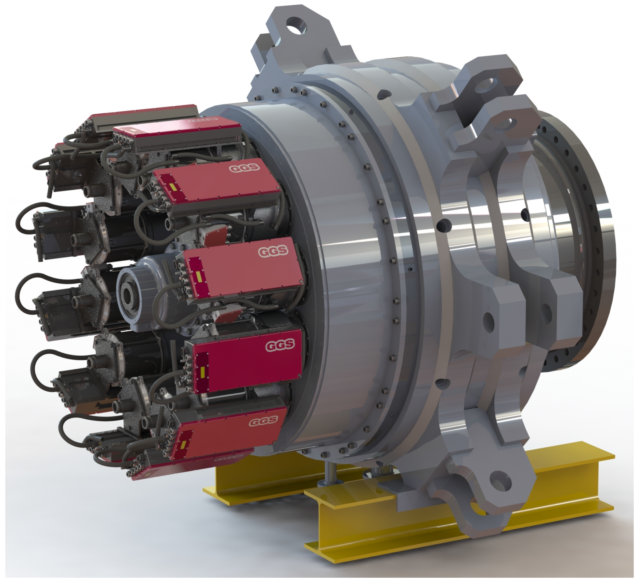
2.1. Drive Train Concept and Reduced-Order Model

The wind turbine (WT) drive train shown in Figure 1 consists of two stage epicyclical split gears, a spur gear for power distribution and twelve epicyclic split gears directly connected to each generator. Each single generator feeds its own AC-DC converter (see the rectangular devices in Figure 1). All converters are connected via DC bus to a common grid-side DC-AC converter (not shown in Figure 1).
The overall ratio i g from the low speed shaft to the high-speed shafts connected to the generators is i g = 438 . From a control-oriented point of view, an ideal gearbox with ratio 1 is considered, which simplifies the equations of motion for the drive train. For the purpose of comparing simulation results of the reduced-order model with more complex rigid body models, a gearbox ratio can be implicitly considered in the proposed control approach.
In this paper, a WT model with four degrees-of-freedom (4-DOF) is used as a baseline model. Hereby, the tower top deflection, the drive train rotation and especially the blade tip deflection are assumed to be sensitive to wind speed variations. The complete model consists of several submodels for the mechanical structure, the aerodynamics, as well as the dynamics of the pitch system and the multi-generator/converter system. Note that the main sources of uncertainty are caused by the unmodeled rotor blade deflection in an edge-wise direction and of each individual rotor blade in a flap-wise direction. Therefore, the DOFs of the model are the collective horizontal tip displacements of the rotor blade tips in a flap-wise direction y B , the displacement of tower top in the wind direction denoted by y T and the rotor and generator rotational angle θ r and θ g . The drive train is modeled by two rigid bodies joined with a torsionally elastic coupling, as described in [17]. The equations of motion of the four DOF yields four coupled differential equations. The state-space model of WT is given as follows
x ˙ = A x + B u + g ( x , v )
with the state vector
x = y T y B θ s y ˙ T y ˙ B ω r ω g β T g T ,
where θ s = θ r θ g denotes the shaft torsion angle, β denotes the pitch angle and T g denotes the collective generator torque. The input vector is
u = β d T g , d T ,
where β d denotes the demanded pitch angle and T g , d the demanded collective generator torque. The system matrix of (1) is
A = 0 0 0 1 0 0 0 0 0 0 0 0 0 1 0 0 0 0 0 0 0 0 0 1 1 0 0 k T m T N k B m T 0 d T m T N d B m T 0 0 0 0 k T m T k B m B N k B m T 0 d T m T d B m B N d B m T 0 0 0 0 0 0 k S J r 0 0 d S J r d S J r 0 0 0 0 k S J g 0 0 d S J g d S J g 0 1 J g 0 0 0 0 0 0 0 1 τ 0 0 0 0 0 0 0 0 0 1 τ g
and the input matrix is as follows
B = 0 7 × 1 0 7 × 1 1 τ 0 0 1 τ g ,
where N denotes the number of blades, k B denotes the effective flap-wise stiffness parameter, k S the drive train stiffness parameter, k T the effective tower fore-aft stiffness parameter, m T the effective mass of nacelle-tower motion, J r the rotor inertia and J g the total inertia of the generators, τ denotes the delay time constant of a reduced-order model of the pitch-dynamics and τ g denotes a common delay time constant of the torque dynamics of the multi-generator system. The WT model (1) has constrained controllable inputs since both the generators and the pitch drive mechanism are limited in the control range
0 T g T g , m a x , 0 β 90 , | β ˙ | 10   m / s
The vector g in Equation (1) nonlinearly depends on the rotor speed and the pitch angle, which are states of the system and the undisturbed wind speed v far in front of the rotor
g ( x , v ) = 0 4 × 1 1 N m B F T ( x , v ) 1 J r T r ( x , v ) 0 3 × 1 ,
where F T denotes the thrust force acting on the rotor and the aerodynamic rotor torque T r . The rotor torque
T r = 1 2 ρ a i r π R 3 v 2 C Q ( λ , β )
and also the thrust force
F T = 1 2 ρ a i r π R 2 v 2 C T ( λ , β )
depend on the pitch angle β, the wind speed v and the aerodynamic torque coefficient C Q or aerodynamic thrust coefficient C T . Both depend on the tip speed ratio ratio λ = ω r R v , where ρ a i r denotes the air density and R denotes the rotor radius. The rotor torque and thrust force are therefore nonlinearly dependent on the wind speed, the rotor speed and the pitch angle.
Note that (5) is derived directly (without any linearization) by the aerodynamic rotor torque (6) and thrust force (7). This form is well suited for a transformation into a Takagi-Sugeno (TS) form [15] proposed in [17]. Here, the nonlinear term g ( x , v ) is first written as a product of a matrix and the state vector x and then reformulated into a TS structure using the sector nonlinearity approach [18]. This approach yields an exact representation of the nonlinear functions defined on a compact set and is used as an control-oriented model for the optimal controller design proposed in [19] and applied in Section 2.3.
The multi-generator/converter dynamics is modeled by a bank of first order delay systems illustrated in Figure 2. The baseline model (1) and the bank of first order systems can be combined to an augmented switched system with the state vector
x a = y T y B θ s y ˙ T y ˙ B ω r ω g β T g , 1 T g , 12 T .
The switch position (on/off) in Figure 2 represents the current status of each generator (healthy/total failure). Here, first it is assumed that the multi-generator is healthy or the i’th generator has totally failed, where up to four faults can simultaneously occur. Second, the fault detection and isolation (FDI) problem is not considered in this work. Instead it is assumed that the on-board electronics of the generator/converter unit are able to detect and isolate a generator fault. To accomplish this, an observer-based FDI scheme is proposed in [14] and experimentallx validated in [20] to detect and isolate a speed sensor and actuator fault in wind turbine drive trains with a single generator.
An alternative reduced-model is illustrated in Figure 3 and formalized in Equation (9). It is equivalent only if n { 1 , , N } with n = N k and k = 0 , , k m a x , wherein a maximum number of k m a x = 4 partial generator failures are taken into consideration:
T ˙ g , s i n g l e = 1 τ g T g , s i n g l e + 1 τ g sat T g , d n , T g = n · T g , s i n g l e
with
sat x = x if x T g , m a x N T g , m a x N otherwise ,
where T g , s i n g l e denotes the torque of a single generator unit, N denotes the total number of generator units, n is the number of faulty units and τ g represents the common delay time constant of each generator unit.

2.2. Baseline Controller

The baseline controller of a wind turbine is usually designed separately for the different load regions (partial load region, transition respectively upper partial load region, full load region) [21], see Figure 6. In the partial load region below the rated wind speed, the pitch angle is kept at the fine pitch angle (usually β = 0 ), where maximum energy extraction is possible, while the total torque of the generators is adjusted such that the turbine is operating around the optimal tip speed ratio and thereby around the maximum power coefficient. The standard approach is a deterministic squared-law for the generator torque with dependence on the rotor speed
T g , d = k o p t ω r 2
with the coefficient k o p t following the optimal torque, such that the rotor is constantly running around the optimal tip speed ratio. In the whole partial load region, the pitch angle is kept at a constant value of β = 0 .
In the transition region, the generator torque is raised to the maximum value using a fast controller
T g , d = T g , o p t , S P , t r q + Δ T g , d , Δ T g , d = k ω r , t r q Δ ω r k I , t r q Δ ω r d t ,
where T g , o p t , S P , t r q denotes the desired rated collective (total) generator torque, k ω r , t r q and k I , t r q denotes the controller coefficient. In the full load region above the rated wind speed, only the pitch angle is adjusted to control the rotor speed around the desired rated rotor speed set point ω r , S P where T g , d = T g , m a x . Increasing the pitch angle reduces the aerodynamic lift force at the rotor blades and thereby leads to a reduced rotor torque. For the pitch control design in the full load region, the wind turbine state space model (3) is thus considered without an explicitly demanded generator torque and only the pitch angle is used as an input. The control law is given as follows
β d = i = 1 N r h i ( β ) ( k i T Δ x i + k I , i x I )
with Δ x i = x x i where x i denotes the states of the i’te stationarity point and h i ( β ) are the membership function, which fulfil the convex sum condition
0 h i ( β ) 1 , i = 1 N r h i ( β ) = 1 .

2.3. Optimal Controller Design for the Full-Load Region

The details of the Linear–quadratic regulator (LQR) design for wind turbine models in Takagi-Sugeno form and a formal stability analysis are proposed in [19]. In the following, the necessary steps are presented for the practical controller design. In this section, the matrices k ˜ i T = k i T k I , i of the control law (12) are designed separately for each linear submodel by means of the LQR design with the augmented state vector
x a = y T y B θ s y ˙ T y ˙ B ω r ω g β x I T
where
x I : = ω r ω r , S P d t .
The LQR controller design minimizes the functional
J = 0 x ˜ T Q x ˜ + u T R u d τ ,
with the weighting matrices Q and R. In order for these to be determined, the maximal absolute values of the contributing states first have to be estimated. For the wind turbine model, the following estimates are taken: y T , max = 1 . 5 m , y B , max = 10 m , θ s , max = 0 . 002 rad , y ˙ T , max = 0 . 2 m s , y ˙ B , max = 2 m s , ω g , max = ω r , max = 1 . 57 rad s , β max = 1 . 57 rad .
Subsequently, the individual states are weighted with relative weights, where the state x 6 = ω r is weighted most since it is the primary quantity to be controlled: Q 1 = 0 , Q 2 = 0 , Q 3 = 2 × 10 9 , Q 4 = 0 . 02 , Q 5 = 0 . 1 , Q 6 = 1 . 57 , Q 7 = 0 , Q 8 = 1 . 5706 × 10 6 , Q I = 0 . 05 .
In the final weighting matrix, the relative weights are divided by the squares of estimated maximum absolute values to take account the magnitudes of the individual states:
Q = diag Q 1 y T , max 2 Q 2 y B , max 2 Q 3 θ s , max 2 Q 4 y ˙ T , max 2 Q 5 y ˙ B , max 2 Q 6 ω r , max 2 Q 7 ω g , max 2 Q 8 β max 2 Q I .
The weight of the control input is chosen as R = 1 .

3. Fault Tolerant Control Using Adaption of Reference Signals

In this section, the impact on the closed loop dynamics of the total generator faults (up to four) that occurred is considered. First, an FTC scheme with an adaptation of the reference signal is proposed. Second, the improvement is illustrated by means of steady state operation in the partial and full load region and the impact on the closed-loop dynamics is shown by rotor acceleration tests.

3.1. Fault Dependent Adaptation of the Reference Signals

The working principle of the reference signal adaptation is illustrated by the block diagram in Figure 4.
In contrast to an equidistant nominal distribution of N generator torques (see the first left block in Figure 2 and Figure 3), the adaptation scheme exploits the known number n of healthy generators. Note: In the last section it was assumed that the number of failures is known. If a generator failure occurs, the reference signals of the remaining generators increases. This works as long as the saturation has not been reached. The effect on the overall system is investigated in the next subsections.

3.2. Fault Tolerant Interaction between the Partial and Full Load Region

In Figure 5, the different control zones for the fault free case 12 / 12 (also shown in Figure 6) and the faulty cases 12 / n with n = 12 k for k = 1 , , 4 generator faults as total single generator failures are illustrated by plotting the torque versus the rotor speed. Typically, there is a cut-in rotor speed ω r , 1 = 0 . 72 (refers to the NREL benchmark WT [22]) which is shown in Figure 6. Due to a fault in k = 1 , , 4 single generators, the maximum controllable torque gradually decreases. The multi-generator drive train is fault-tolerant as long as the demanded torque is less than or equal to the cumulated generator saturation of the remaining fault-free generators. This has implications in the full load region ( ω r > ω r , S P , see Figure 6) and the pitch control loop due to the lower rated power. This is made clear in Figure 7, where the curve of stationary pitch angle value vs. the wind speed’s upward shift is dependent on increasing generator torque losses. This means that for k = 1 , , 3 generator fault(s), a reduction of the maximum controllable torque is caused in the upper partial load region defined by ω r , S P , t r q ω r ω r , S P and for k = 4 a reduction of the maximum controllable torque in the lower partial load region ω r , 2 ω r < ω r , S P , t r q is seen, see Figure 6. That results in an acceleration of the rotor and if the rotor speed reaches a value above the nominal speed, the pitch controller for the full load operation is activated. The pitch controller has the speed error (difference of the current rotor speed and its nominal speed) as an input and produces the collective reference pitch angle for the pitch drives. An increasing pitch angle greater than zero causes a reduction of the aerodynamic torque in such a way that this is adapted to the limited maximum torque. The following pseudo-code illustrates the overall behavior of the generator torque and pitch control in the partial and full load region.
Algorithm 1: FTC hybrid wind turbine control scheme
Energies 10 00149 i001
In the above algorithm, PI-cntrl-Tg[ e ( t ) ] denotes the PI generator torque controller (11) in the upper partial load, TS-cntrl-beta[ e ( t ) , x ( t ) ] denotes the pitch controller (12) in the full load region and FT-cntrl[ T g , d ( t ) ] represents the model-based fault tolerant control scheme using (9).

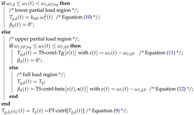
3.3. Rotor Acceleration Test of the Multi-Generator Drive Train

Figure 8 shows a comparison between the fault-free case ( n = N ) and faulty case ( n = 8 ) during rotor acceleration from cut-in to medium strong wind speed. It can be seen as in the previous stationary consideration, but now more clearly the fault tolerant control characteristics of the baseline controller in combination with an fault dependent adaptation of the demanded generator torque can be observed:
  • partial load: remaining healthy generators compensate the occurred generator faults
  • full load: previous engagement of pitch control compensates for the decreased maximum total torque

4. Transient Behavior of Fault Tolerant Control Scheme

In this section the transient behavior in the presence of abrupt generator faults in the partial and full load region is considered. Finally, a classic control design is used for the active damping of weakly damped torsional vibrations.

4.1. Transient Behavior in the Partial Load Region

Figure 9 shows the impact of an abrupt fault on the system dynamics. Here, the controller is able to reach the demanded generator torque in a sufficient time. Unfortunately, the excited oscillation of the torsion angle cannot be compensated for by the same strategy. For this purpose, an active damping is designed in Section 4.3.

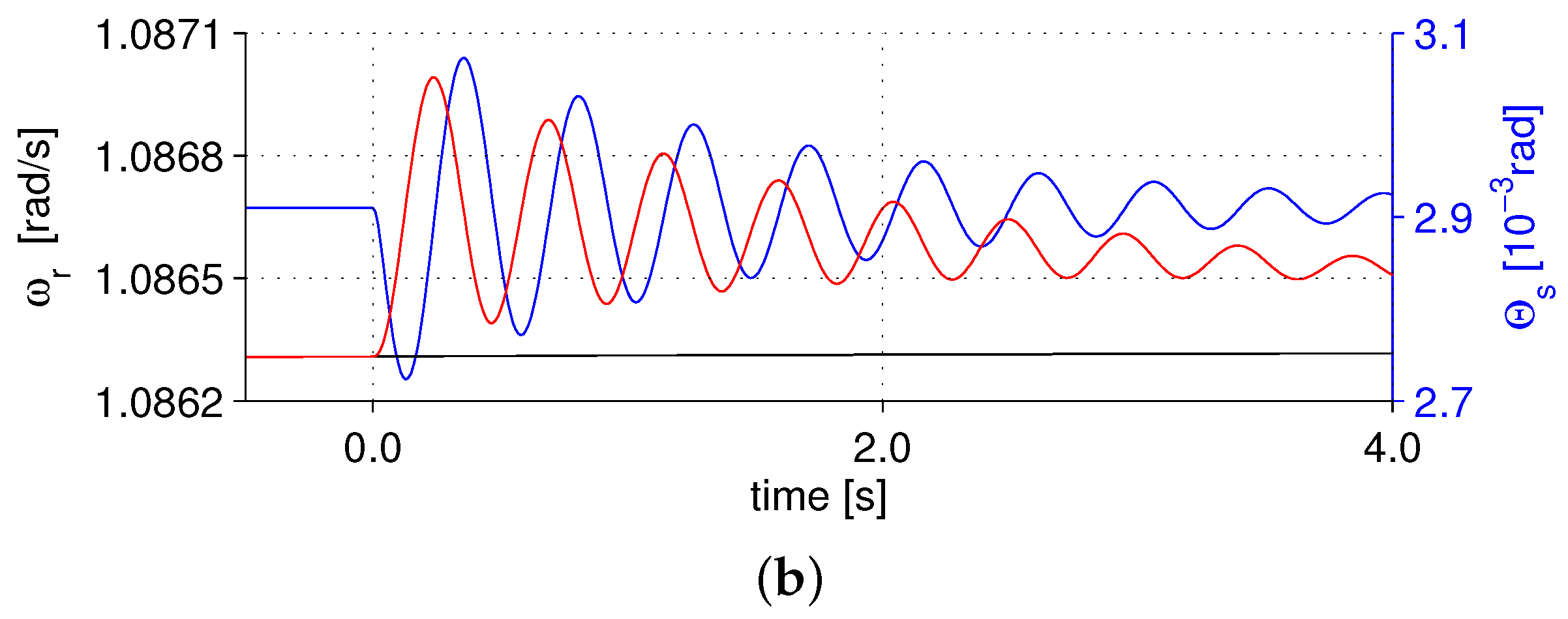
4.2. Transient Behavior in the Full Load Region

The transient behavior in the full load region is illustrated in Figure 10. Here, by lowering the full load region the pitch controller is able to reach the demanded rotor speed in a sufficient time. As before, the excited oscillation cannot be compensated for by the same strategy. For this purpose, an active damping is designed in the next subsection.

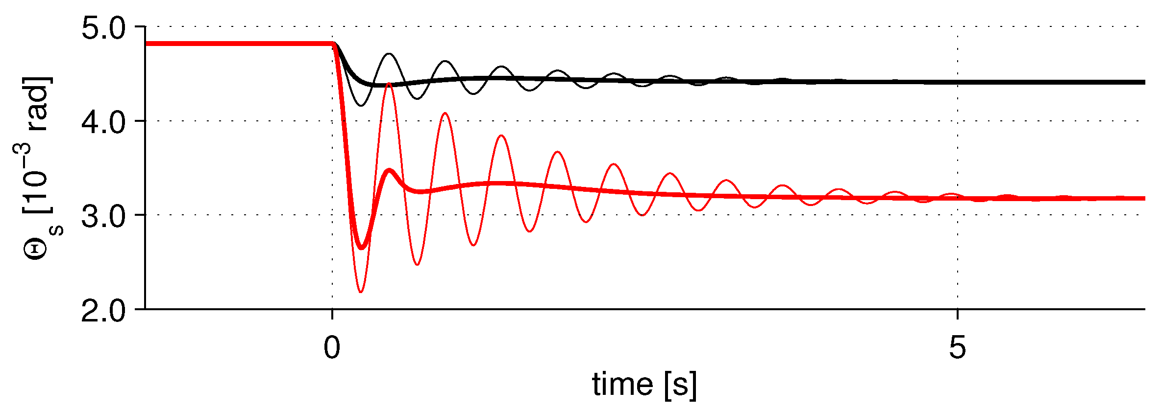
4.3. Active Vibration Damping

The active damping based on the superposition of the demanded generator torque T g , d calculated with (10) or (11) by
T ˜ g , d = T g , d + Δ T g , d
with the control law
Δ T g , d = k d a m p θ ˙ s .
The control design follows the classic approach in [23] and is based on the state space model (3). In Figure 11, two different cases ( n = 11 ,   n = 8 ) are illustrated by plotting the shaft torsion angle without and with active damping by (19).

5. Conclusions and Future Works

In this paper, a distributed generator drive train is studied under fault conditions. A control-oriented model is proposed and a controller structure with two layers is studied. The upper layer is the baseline controller, which is separated into a partial load region with generator torque as the actuating signal and the full-load operation region with a collective pitch angle as the actuating signal. The lower layer is responsible for FTC characteristics of the distributed generator drive train, which is based on an adaptation of the demanded generator torque. The practicability is illustrated by means of steady state and rotor acceleration tests operation in the partial and full load region.
An open problem is the delayed detection of generator faults in real systems. The delayed detection causes a mismatch of the distribution of the generator torques, which leads to an intermittent increasing of the total generator torque and a decreasing of the rotor speed. It must be studied in detail whether a torque controller in the upper partial load range is able to avoid significant drop of the rotor speed. Further, the controller robustness for different load cases has to be tested with a much more detailed wind turbine model, which is i.a. implemented in the aero-elastic simulation package FAST (Fatigue, Aerodynamics, Structures, and Turbulence) by the National Renewable Energy Laboratory of the U.S. Department of Energy (NREL).

References

  1. Cohen, J.; Schweizer, T.; Laxson, A.; Butterfield, S.; Schreck, S.; Fingersh, L.; Veers, P.; Ashwill, T. Technology Improvement Opportunities for Low Wind Speed Turbines and Implications for Cost of Energy Reduction; NREL/TP-500-41036; NREL: Golden, CO, USA, 2008. [Google Scholar]
  2. Robb, D. The return of the Clipper Liberty wind turbine. Power 2008, 152, 74. [Google Scholar]
  3. Giger, U.; Arnaudov, K. New drive train design for ultra large 15 MW wind turbines. In Proceedings of the International Conference on Gears, Garching, Germany, 7–9 October 2013.
  4. Sloth, C.; Esbensen, T.; Stoustrup, J. Robust and fault-tolerant linear parameter-varying control of wind turbines. Mechatronics 2011, 21, 645–659. [Google Scholar] [CrossRef]
  5. Odgaard, P.F.; Stoustrup, J. Fault tolerant control of wind turbines using unknown input observers. In Proceedings of the IFAC Symposium on Fault Detection, Supervision and Safety of Technical Processes, Mexico City, Mexico, 29–31 August 2012; pp. 313–318.
  6. Odgaard, P.F.; Stoustrup, J.; Kinnaert, M. Fault Tolerant control of wind turbines—A benchmark model. In Proceedings of the IFAC Symposium on Fault Detection, Supervision and Safety of Technical Processes, Barcelona, Spain, 30 June–3 July 2009; pp. 155–160.
  7. Sami, M.; Patton, R.J. An FTC approach to wind turbine power maximisation via T-S fuzzy modelling and control. In Proceedings of the IFAC Symposium on Fault Detection, Supervision and Safety of Technical Processes, Mexico City, Mexico, 29–31 August 2012; pp. 349–354.
  8. Sami, M.; Patton, R.J. Active sensor fault tolerant output feedback tracking control for wind turbine systems via T-S model. Eng. Appl. Artif. Intell. 2014, 34, 1–12. [Google Scholar]
  9. Sami, M.; Patton, R.J. Fault tolerant adaptive sliding mode controller for wind turbine power maximisation. In Proceedings of the 7th IFAC Symposium on Robust Control Design, Aalborg, Denmark, 20–22 June 2012; pp. 499–504.
  10. Rotondo, D.; Nejjari, F.; Puig, V.; Blesa, J. Fault tolerant control of the wind turbine benchmark using virtual sensors/actuators. In Proceedings of the IFAC Symposium on Fault Detection, Supervision and Safety of Technical Processes, Mexico City, Mexico, 29–31 August 2012; pp. 114–119.
  11. Simani, S.; Castaldi, P. Active actuator fault-tolerant control of a wind turbine benchmark model. Int. J. Robust Nonlinear Control 2014, 24, 1283–1303. [Google Scholar] [CrossRef]
  12. Badihi, H.; Zhang, Y.; Hong, H. Fuzzy gain-scheduled active fault tolerant control of a wind turbine. J. Frankl. Inst. 2014, 351, 3677–3706. [Google Scholar] [CrossRef]
  13. Badihi, H.; Zhang, Y.; Hong, H. Wind turbine fault diagnosis and fault-tolerant torque load control against actuator faults. IEEE Trans. Control Syst. Technol. 2015, 23, 1351–1372. [Google Scholar] [CrossRef]
  14. Georg, S.; Schulte, H. Actuator fault diagnosis and fault-tolerant control of wind turbines using a Takagi-Sugeno sliding mode observer. In Proceedings of the International Conference on Control and Fault-Tolerant Systems (Sys-Tol), Nice, France, 9–11 October 2013; pp. 516–522.
  15. Takagi, T.; Sugeno, M. Fuzzy identification of systems and its application to modeling and control. IEEE Trans. Syst. Man Cybern. 1985, 15, 116–132. [Google Scholar] [CrossRef]
  16. Jonkman, J.M.; Buhl, M.L., Jr. FAST User’s Guide; Technical Report NREL/EL-500-38230; National Renewable Energy Laboratory: Golden, CO, USA, 2005. [Google Scholar]
  17. Georg, S.; Schulte, H.; Aschemann, H. Control-oriented modelling of wind turbines using a Takagi-Sugeno model structure. In Proceedings of the IEEE International Conference on Fuzzy Systems, Brisbane, Australia, 11–15 June 2012; pp. 1737–1744.
  18. Tanaka, K.; Sano, M. A robust stabilization problem of fuzzy control systems and its application to backing up control of a truck-trailer. IEEE Trans. Fuzzy Syst. 1994, 2, 119–134. [Google Scholar] [CrossRef]
  19. Georg, S. Fault Diagnosis and Fault-Tolerant Control of Wind Turbines Nonlinear Takagi-Sugeno and Sliding Mode Techniques. Ph.D. Thesis, Fakultät für Maschinenbau und Schiffstechnik, University of Rostock, Rostock, Germany, 2014. [Google Scholar]
  20. Schulte, H.; Georg, S. Hardware-in-the-Loop Test-Bed for benchmarking of fault tolerant control schemes for wind turbines. In Proceedings of the 9th IFAC Symposium on Fault Detection, Supervision and Safety of Technical Processes, Paris, France, 2–4 September 2015.
  21. Burton, T.; Jenkins, N.; Sharpe, D.; Bossanyi, E. Wind Energy Handbook, 2nd ed.; John Wiley & Sons Ltd.: New York, NY, USA, 2011. [Google Scholar]
  22. Odgaard, P.F.; Johnson, K. Wind turbine fault detection and fault tolerant control—An enhanced benchmark challenge. In Proceedings of the American Control Conference, Washington, DC, USA, 17–19 June 2013; pp. 4447–4452.
  23. van der Hooft, E.L.; Schaak, P.; van Engelen, T.G. Wind Turbine Control Algorithms; Technical Report DOWEC-F1W1-EH-03-094/0; Energy Research Center of the Netherlands (ECN): Delft, The Netherlands, 2003. [Google Scholar]
Figure 1. Wind turbine multi-generator drive train with 12 single generators.
Energies 10 00149 g001
Figure 2. Reduced-order model of multi-generator/converter (Type 1).
Energies 10 00149 g002
Figure 3. Reduced-order model of multi-generator/converter (Type 2).
Energies 10 00149 g003
Figure 4. Reference signal adaptation for demanded generator torque.
Energies 10 00149 g004
Figure 5. Regions of control and demanded generator torque dependent upon number of k = 0 , 1 , , 4 faulty generators.
Energies 10 00149 g005
Figure 6. Regions of wind turbine control; Total Generator torque for the fault-free case dependent upon the rotor angular speed.
Energies 10 00149 g006
Figure 7. Stationary pitch angle values in the full load region dependent upon number of faults.
Energies 10 00149 g007
Figure 8. Rotor acceleration test in partial, transition and full load region: fault-free case, n = N (black line) and faulty case n = 8 (red line), wind speed (blue line).
Energies 10 00149 g008
Figure 9. Generator failure in the partial load region at constant wind speed 8 m/s. (a) otal generator torque T g (red line), demanded torque T g , d (black line), and n N + denotes the number of healthy generators (blue line); (b) rotor speed ω r (red), demanded rotor speed ω r (black), shaft torsion angle Θ s (blue).
Energies 10 00149 g009aEnergies 10 00149 g009b
Figure 10. Generator failure in the full load region at constant wind speed 12 m/s. (a) Total generator torque T g (red line), demanded torque T g , d (black line), pitch angle β (blue line); (b) shaft torsion angle Θ s (bue), demanded angle Θ s (black).
Energies 10 00149 g010
Figure 11. Control performance of active damping systems: Comparison between one (black line) and four total generator failures (red line).
Energies 10 00149 g011

