
Modeling and Maximum Power Point Tracking Control of Wind Generating Units Equipped with Permanent Magnet Synchronous Generators in Presence of Losses


Abstract
:1. Introduction
- Defining a methodology to manage the initialization of WTG models in the presence of power system losses;
- Proposing a control scheme that allows tracking the maximum power point even in the presence of losses;
- Providing a detailed analyses on the structure of the controllers and analytical criteria to choose their parameters according to the system’s desired dynamic behavior.
2. Power System Model
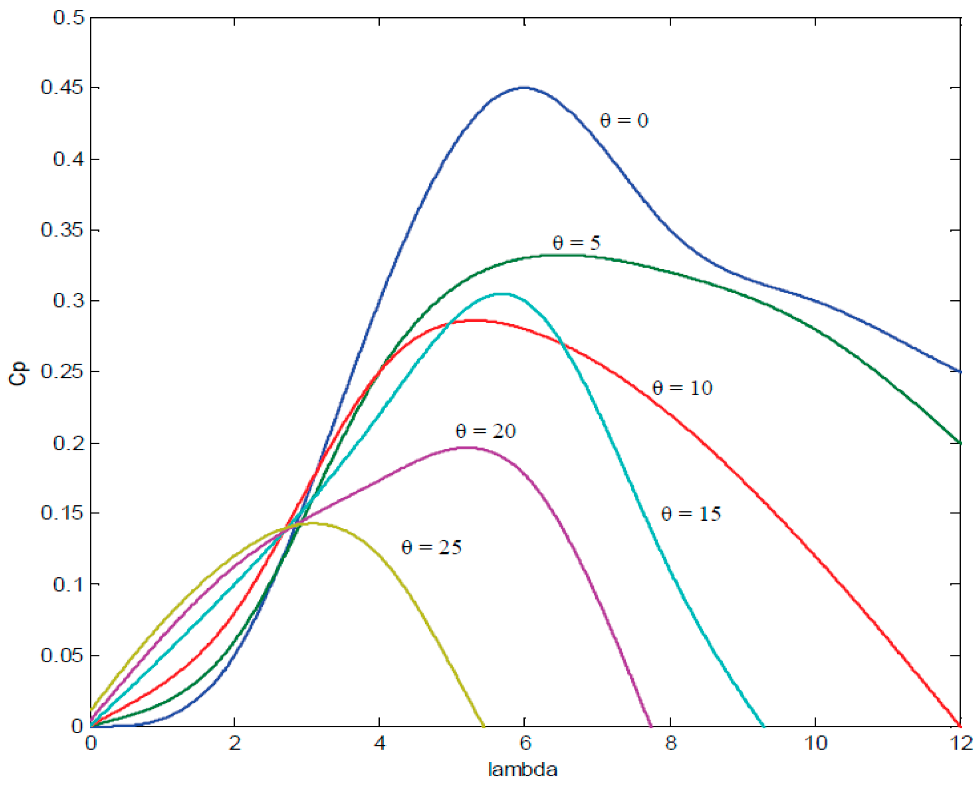
2.1. Wind Turbine Model
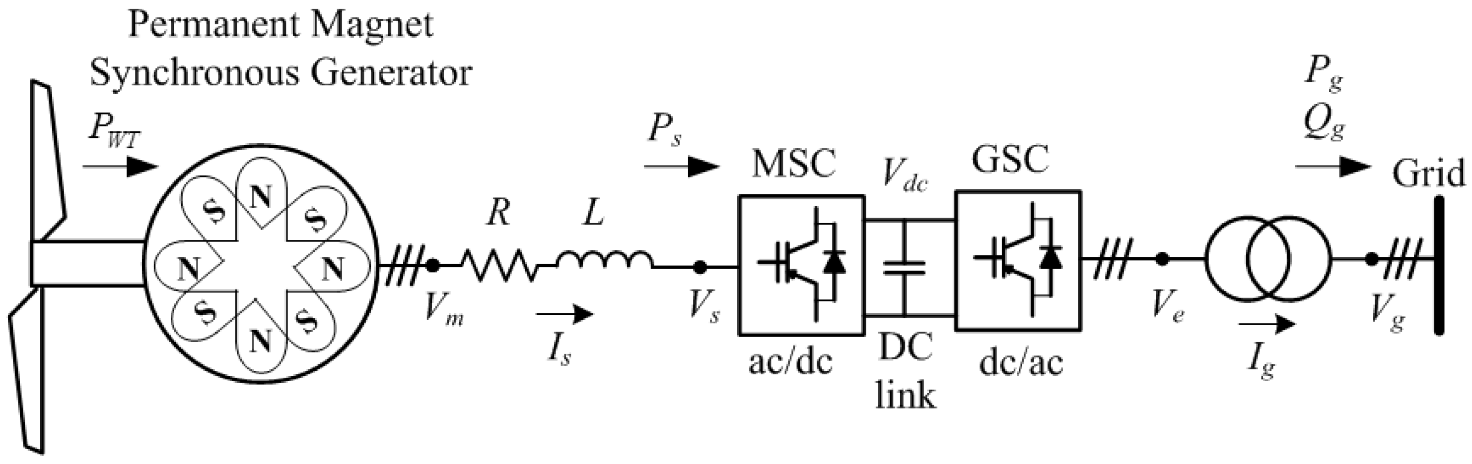
2.2. Permanent Magnet Synchronous Generator Model
2.3. Machine Side Converter Model
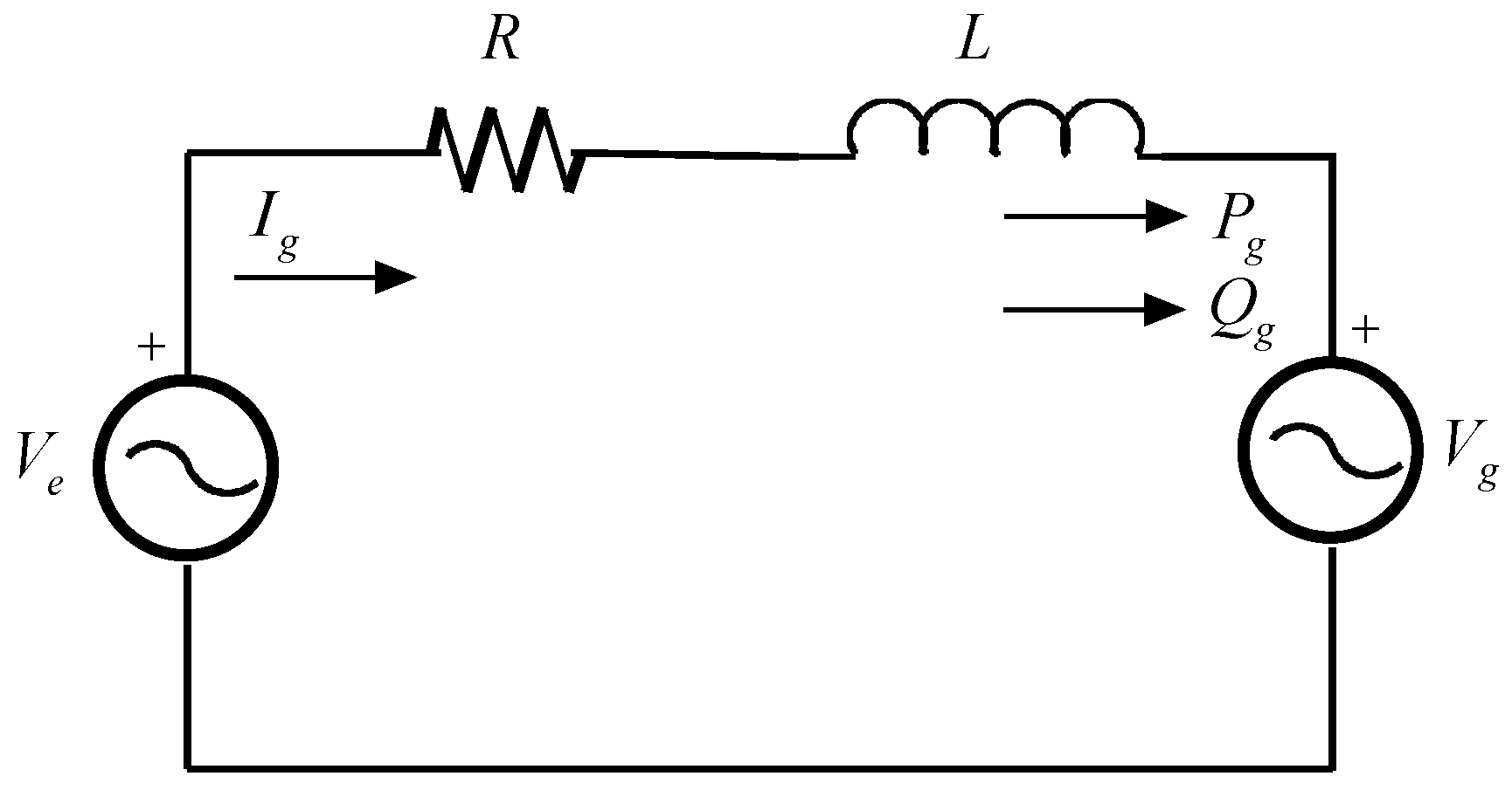
2.4. Grid Side Converter Model
- RT and LT are the connection resistance and the inductance, respectively;
- ved(q) is the direct (quadrature) axis components of the voltage at the AC terminals of the GSC;
- vgd(q) is the direct (quadrature) axis components of the grid voltage and
- igd(q) is the direct (quadrature) axis components of the current flowing in the connection.
3. Initialization of Fundamental Frequency Simulations Starting from Load-Flow Calculation
3.1. Network Side Portion
3.2. Machine Side Portion
4. Application of the Proposed Initialization Procedure
- The connection between the machine and the machine side converter is characterized by resistance R = 0.05 p.u. and an inductance L = 0.05 p.u. (on the machine basis)
- The connection between the GSC and the external network has an equivalent resistance Rt = 0.005 p.u. and an equivalent inductance Lt = 0.05 p.u. (on the machine basis).
5. Fully Rated Converter Wind Generator Unit Control Scheme
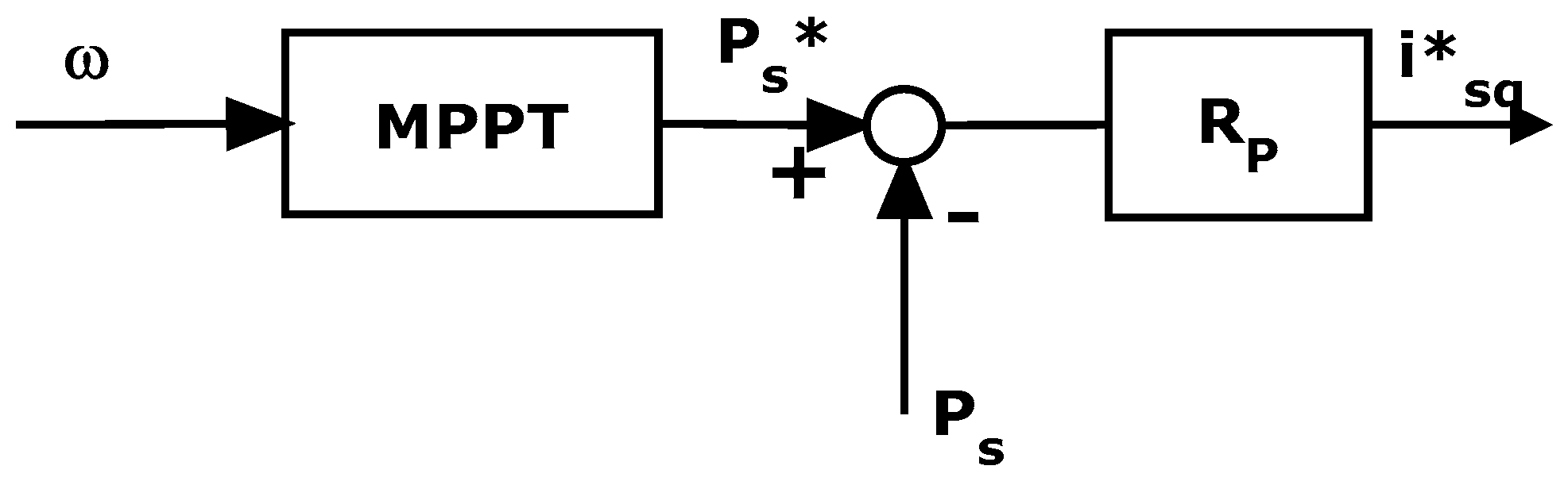
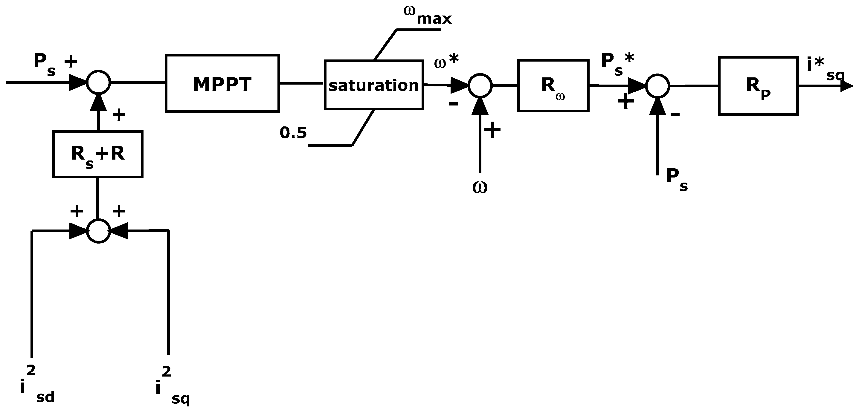
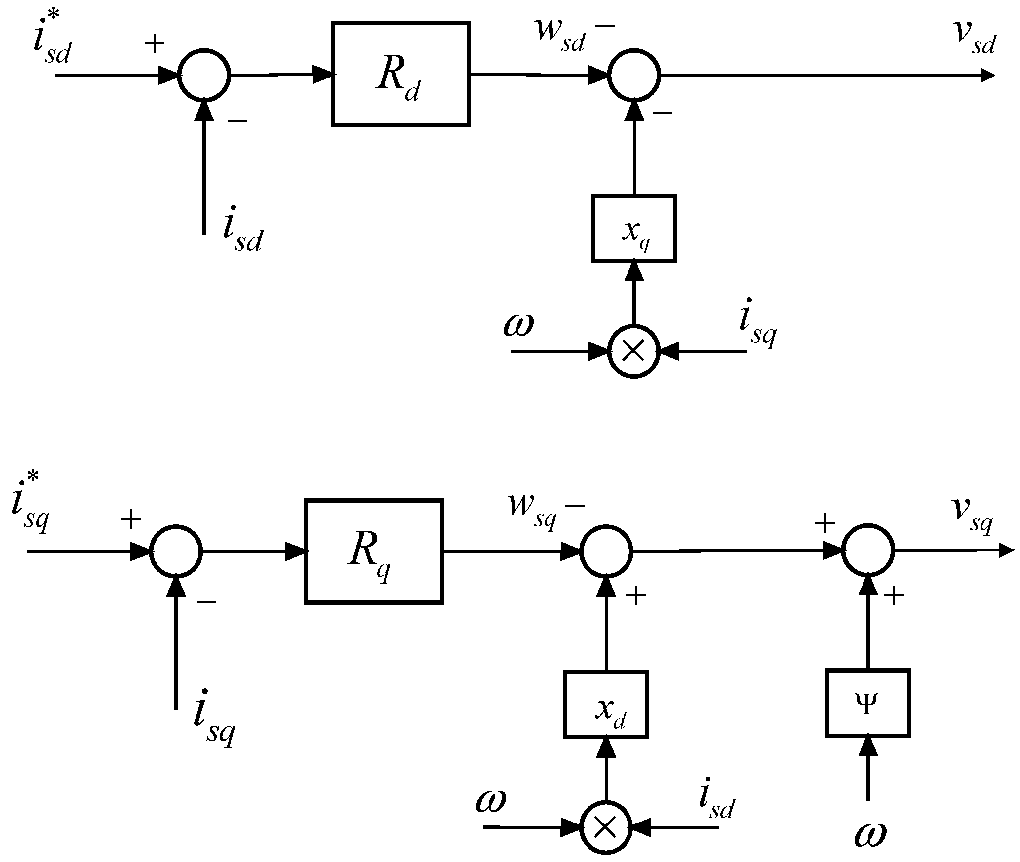
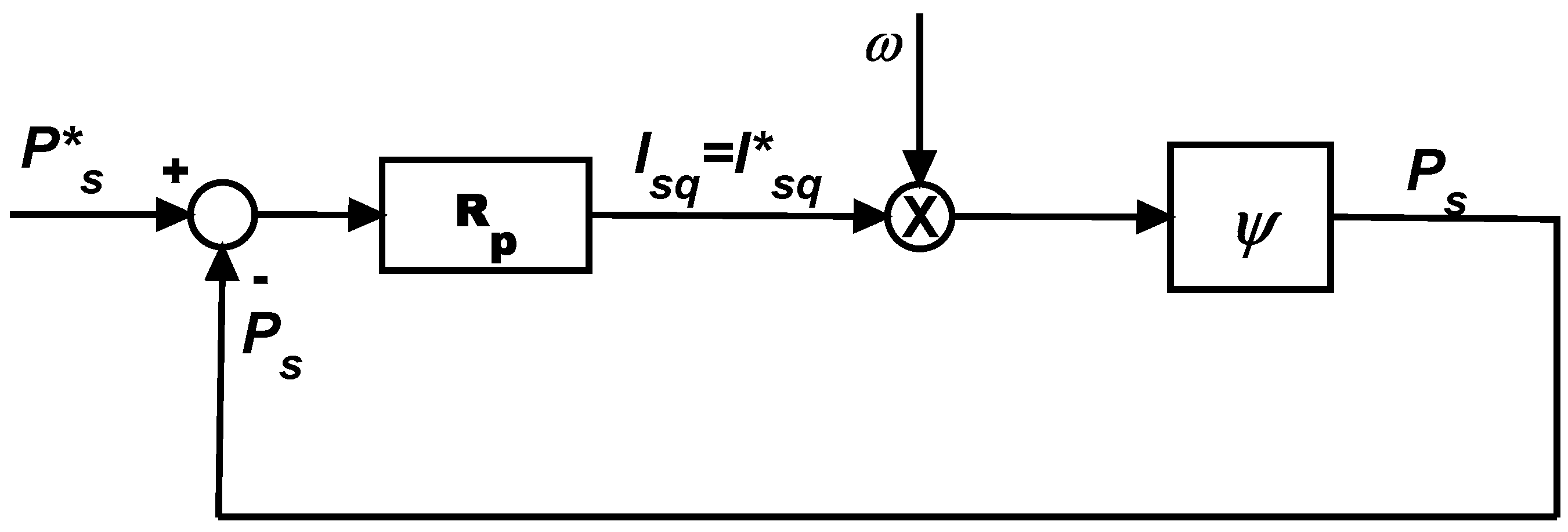
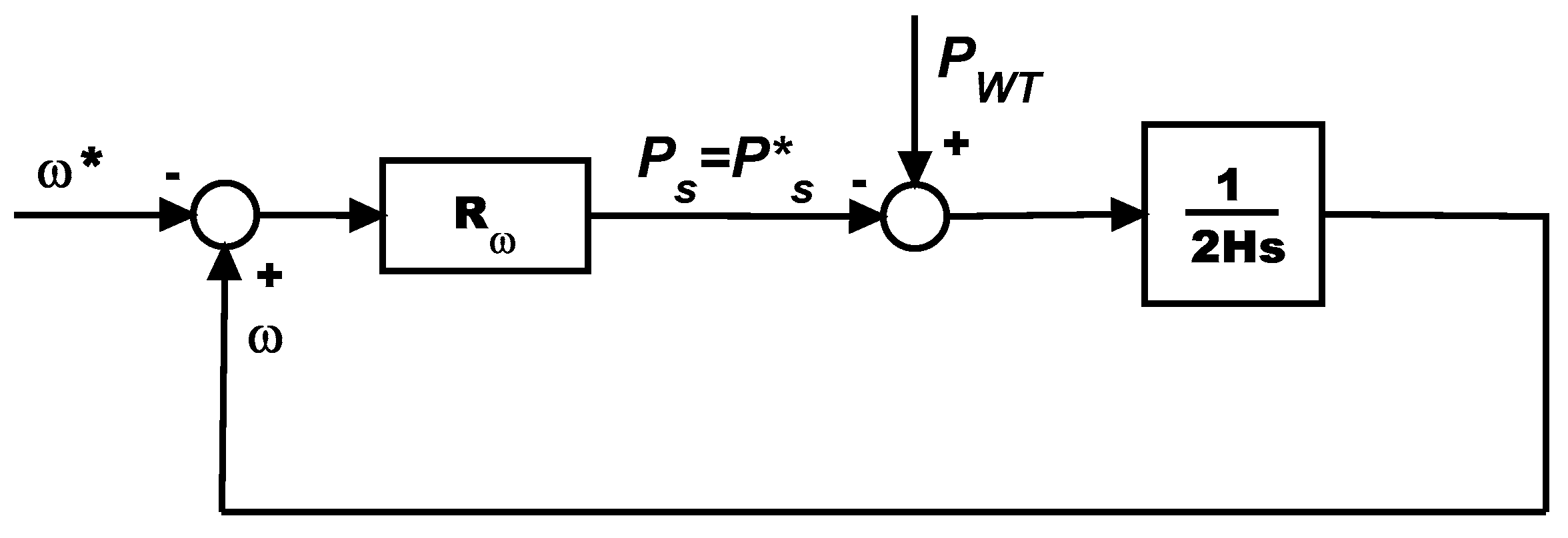
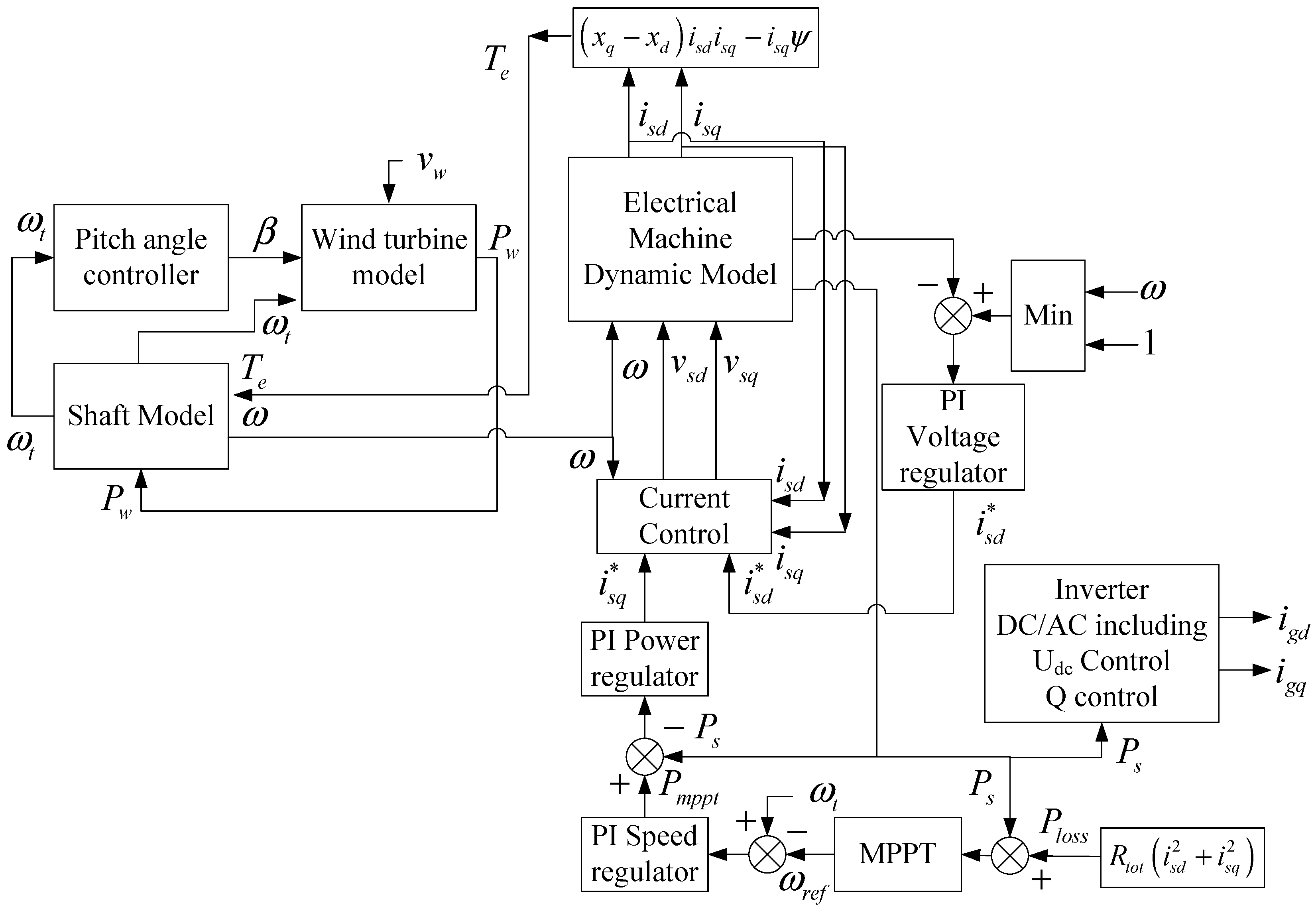
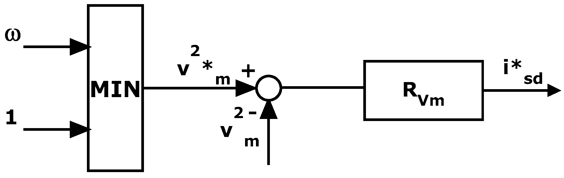
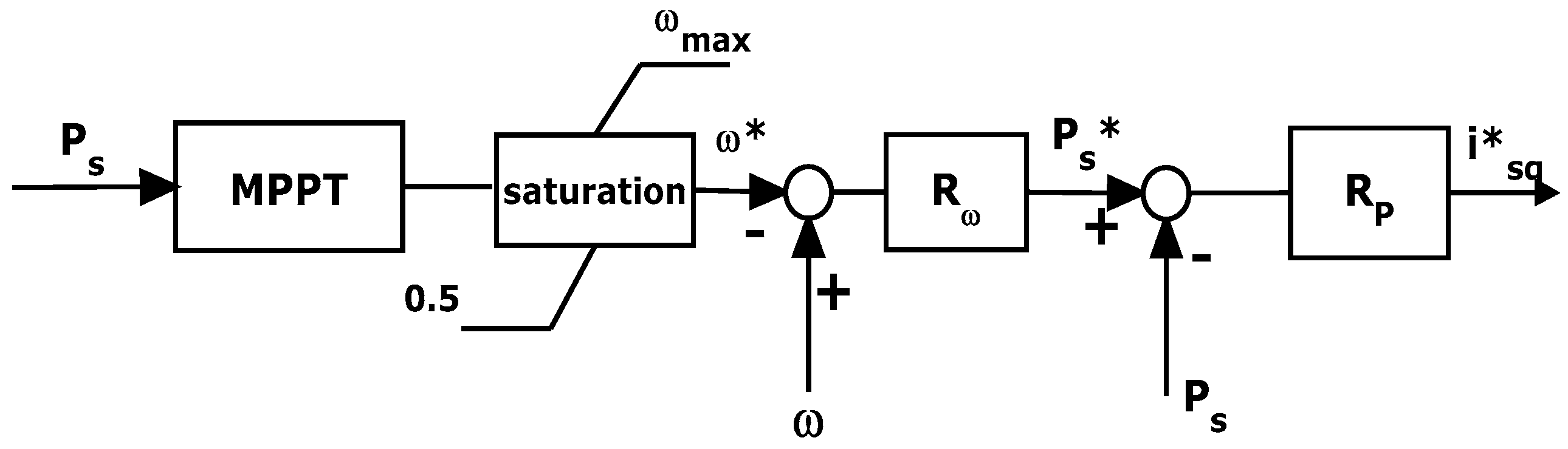
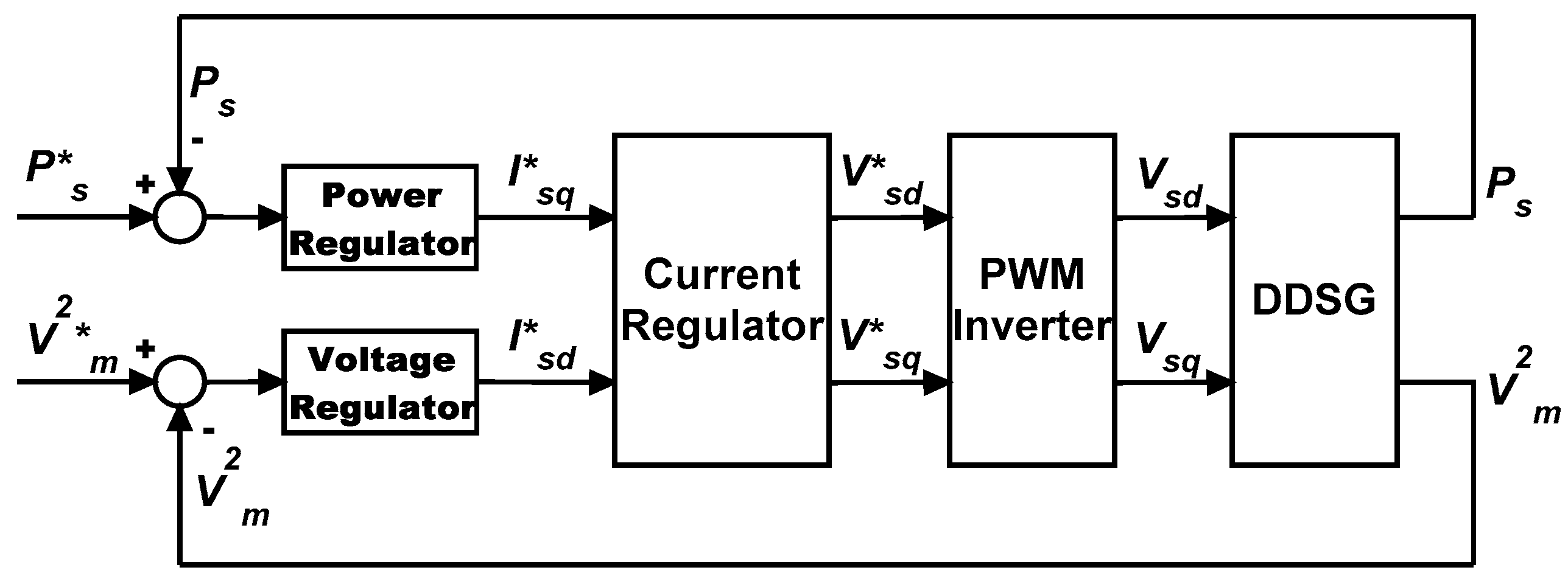
5.1. Machine Side Converter Controller
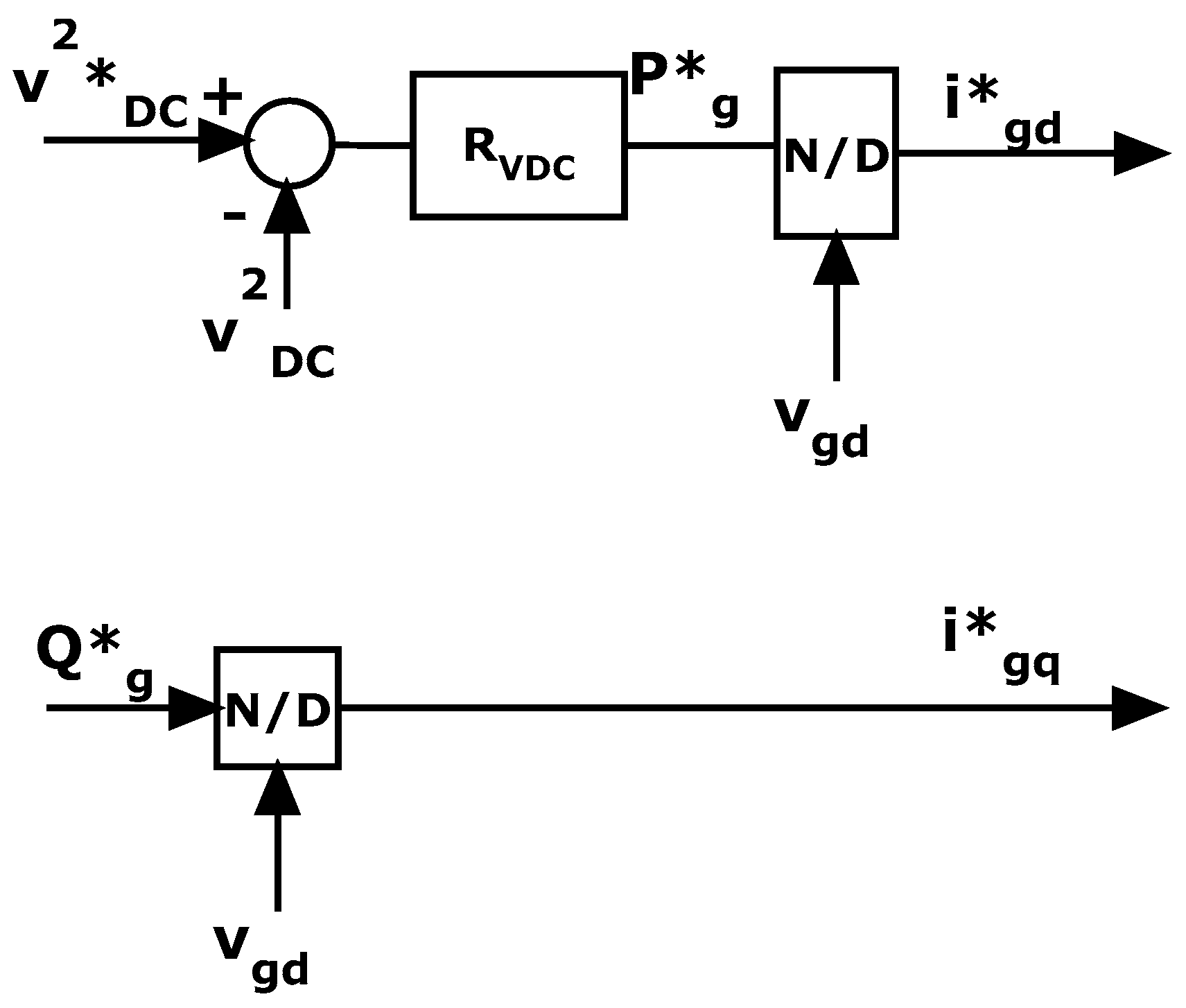
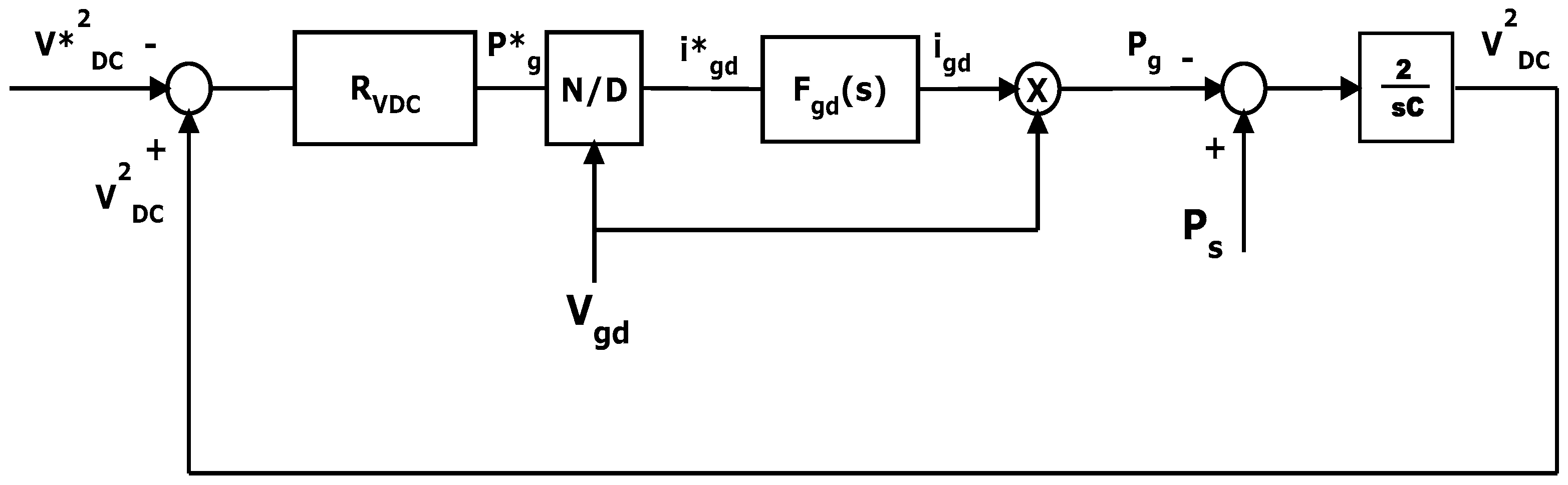
5.2. Grid Side Converter Controller
6. Criteria for the Synthesis of the Wind Turbine Generator Regulators
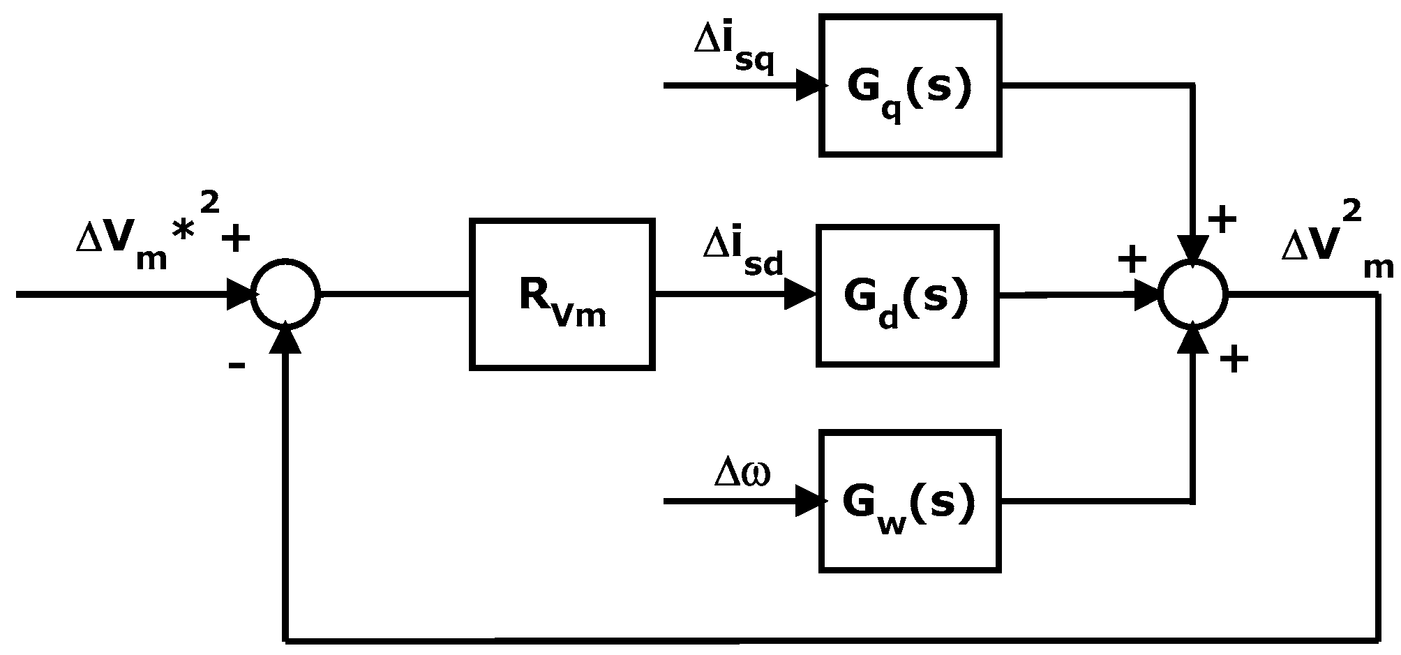
6.1. Machine Side Converter Regulator Synthesis
- Choose a couple of parameters kPvm and kIvm;
- For any value of PWT0 belonging to the range [PWTmin, PWTmax], determine the corresponding initial working point;
- Evaluate vmd0 and vmq0 with Equations (5) and (6) having nullified the time derivatives;
- Solve Equation (42);
- Adjust the values of kPvm and kIvm s.t. for all the values of PWT0: (i) the solutions of Equation (42) have a negative real part; (ii) the solution of Equation (42) with smaller amplitude (i.e., the one that dictates the dynamic behavior of the voltage loop) is (in modulus) sufficiently smaller than the roots of Equation (30) to guarantee that the current loop is much faster than the voltage one.
6.2. Grid Side Converter Regulator Synthesis
6.3. Overall Control System Structure and Summary of the Developed Criteria
- Place the poles of the inner control loop according to Equation (30);
- Place the poles of the active power control loop zeroing the denominator of Equation (33) such that the power dynamics are sufficiently slower than the current one in order to meet Equation (31);
- Place the poles of the speed control loop zeroing the denominator of Equation (35) such that the speed dynamics are sufficiently slower than the active power one in order to meet Equation (34).
- Place the poles of the inner control loop according to Equation (30);
- Place the pole voltage control loop with the procedure described in Section 6.1.
- Place the poles of the inner control loop zeroing the denominator of Equation (47).
- Place the poles of the DC voltage control loop zeroing the denominator of Equation (49) such that the DC voltage dynamics are sufficiently slower than the current one.
- The choice of the Park reference frame such that the network voltage Vg has only a direct axis component [33] creates an algebraic link between the reactive power and the quadrature axis current; therefore, the reactive power dynamics are the same as the quadrature axis current.
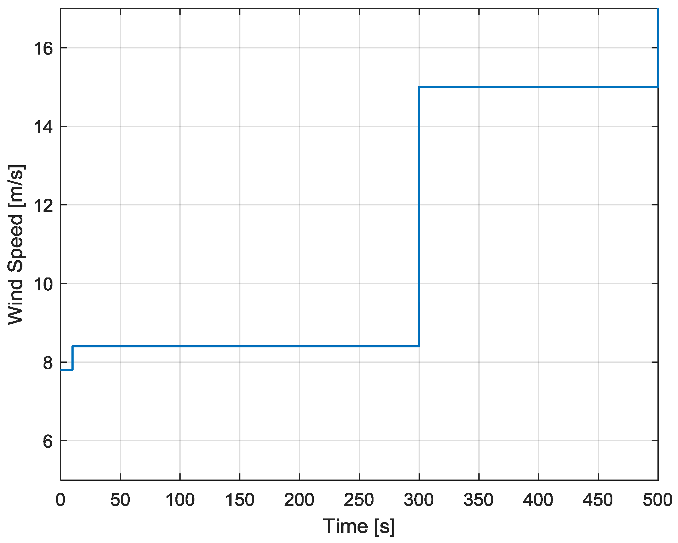
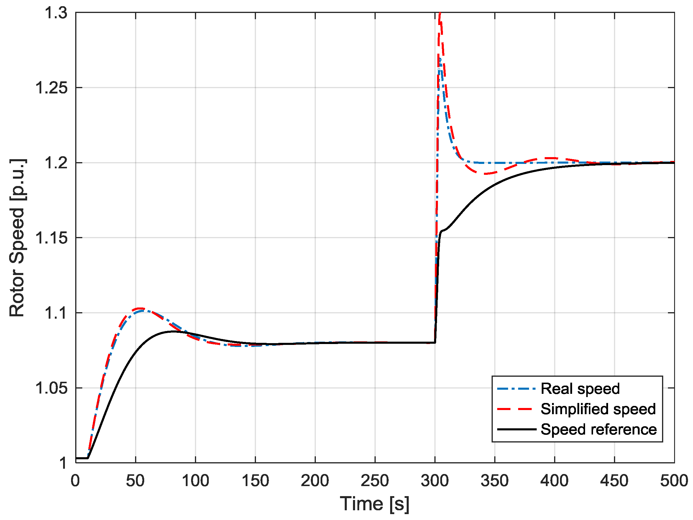
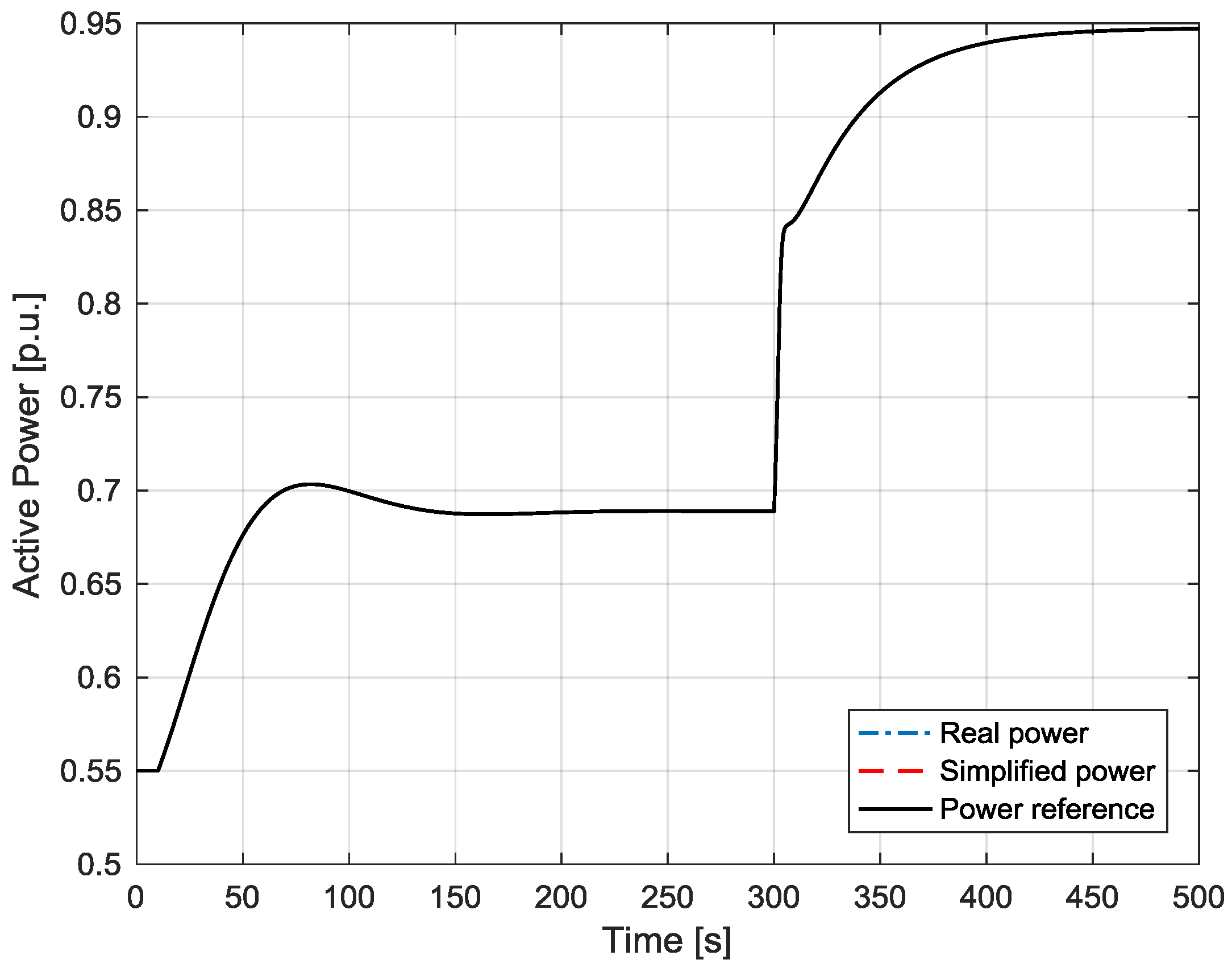
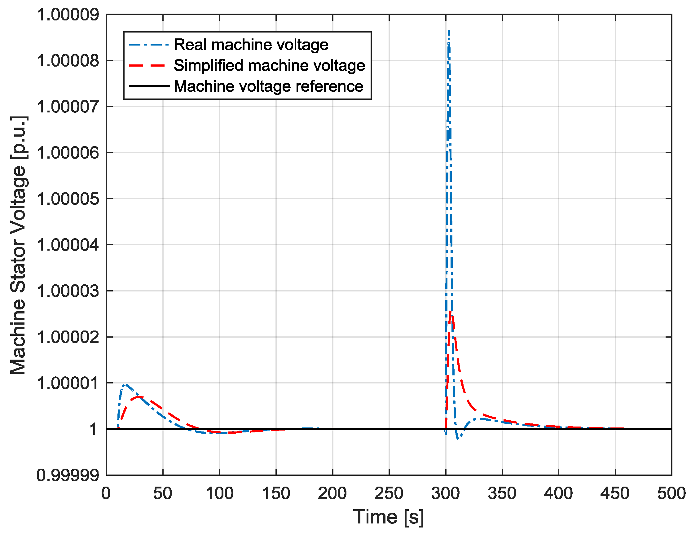
7. Simulations to Validate the Controller Synthesis and the Proposed Simplified Schemes
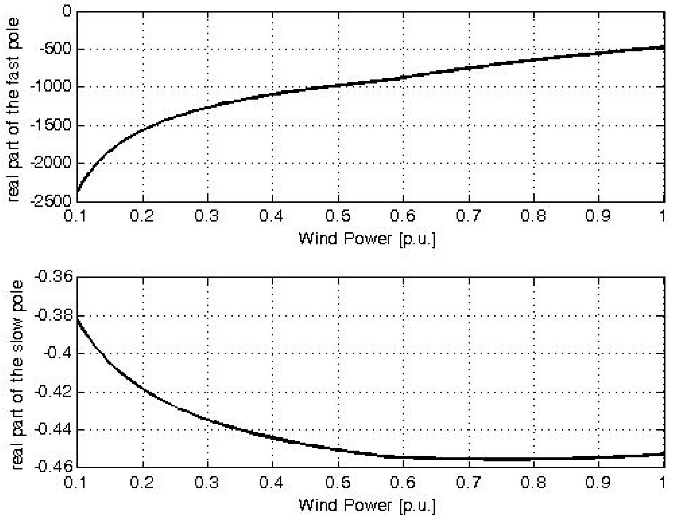
- The poles of the machine currents loop are −27 ±45j; while the poles of the active power and of the speed loops are respectively −1.6 and −0.017 ±0.05j. With these values, the dynamics of the three loops act on different time frames, thus meeting the requirements of Equations (31) and (34).
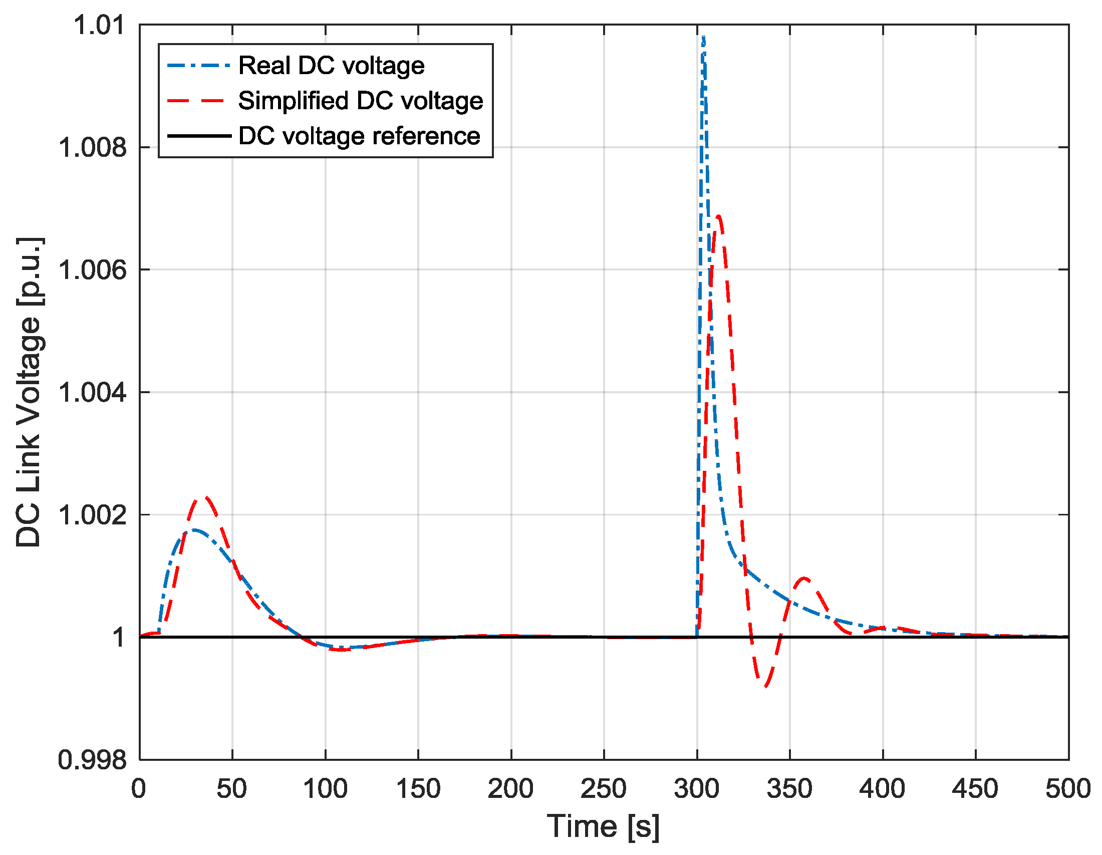
- The poles of the grid current loops are −544 and −115, while the poles of the DC voltage one are −0.02 ±0.02j, which ensures that its dynamics are much slower than the current one.
8. Conclusions
Author Contributions
Conflicts of Interest
References
- Chiradeja, P. Benefit of distributed generation: A line loss reduction analysis. In Proceedings of the 2005 IEEE/PES Transmission and Distribution Conference and Exhibition: Asia and Pacific, Dalian, China, 15–18 August 2005; pp. 1–5.
- Momoh, J.A.; Xia, Y.; Boswell, G.D. An approach to determine distributed generation (DG) benefits in power networks. In Proceedings of the 40th North American Power Symposium, NAPS ‘08, Calgary, AB, Canada, 28–29 September 2008; pp. 1–7.
- Conka, Z.; Hocko, P.; Novak, M.; Kolcun, M.; Gyorgy, M. Impact of renewable energy sources on stability of ewis transmission system. In Proceedings of the 14th International Conference on Environmental and Electrical Engineering, Kraków, Poland, 10–12 May 2014; pp. 75–79.
- Amarasekara, H.W.K.M.; Meegahapola, L.; Agalgaonkar, A.P.; Perera, S. Impact of renewable power integration on VQ stability margin. In Proceedings of the 22nd Australasian Universities Power Engineering Conference, AUPEC 2013, Hobart, Australia, 29 September–3 October 2013; pp. 1–6.
- Davda, A.T.; Parekh, B.R. System impact analysis of renewable distributed generation on an existing radial distribution network. In Proceedings of the 2012 IEEE Electrical Power and Energy Conference (EPEC), Halifax, NS, Canada, 10–12 October 2012; pp. 128–132.
- Delfino, F.; Denegri, G.B.; Invernizzi, M.; Procopio, R. Feedback linearisation oriented approach to Q-V control of grid connected photovoltaic units. IET Renew. Power Gener. 2012, 6, 324–339. [Google Scholar] [CrossRef]
- Bonfiglio, A.; Brignone, M.; Delfino, F.; Invernizzi, M.; Pampararo, F.; Procopio, R. A technique for the optimal control and operation of grid-connected photovoltaic production units. In Proceedings of the 2012 47th International Universities Power Engineering Conference (UPEC), London, UK, 4–7 September 2012.
- Fornari, F.; Procopio, R.; Bollen, M.H.J. SSC compensation capability of unbalanced voltage sags. IEEE Trans. Power Deliv. 2005, 20, 2030–2037. [Google Scholar] [CrossRef]
- Delfino, B.; Fornari, F.; Procopio, R. An effective SSC control scheme for voltage sag compensation. IEEE Trans. Power Deliv. 2005, 20, 2100–2107. [Google Scholar] [CrossRef]
- CEI 0-16 Reference Technical Rules for the Connection of Active and Passive Consumers to the HV and MV Electrical Networks of Distribution Company; Comitato Elettrotecnico Italiano (CEI): Milano, Italy, 2012.
- BWE Technical Guidelines—Generating Plants Connected to the Medium Voltage Network; Bundesverband der Energie- und Wasserwirtschaft (BDEW): Berlin, Germany, 2008.
- RTE Requirements Regulatory Text (Decree 2008-386 dated 23 April 2008). Available online: https://www.legifrance.gouv.fr/affichTexte.do?cidTexte=JORFTEXT000018698004 (accessed on 27 September 2016).
- Power to Ontario on Demand Market Rules—Chapter 4 Grid Connection Requirements; Independent Electricity System Operator (IESO): Toronto, ON, Canada, 2013.
- Gonzalez-Longatt, F.; Bonfiglio, A.; Procopio, R.; Verduci, B. Evaluation of inertial response controllers for full-rated power converter wind turbine (Type 4). In Proceedings of the IEEE PES General Meeting 2016, Boston, MA, USA, 7–21 July 2016.
- Slootweg, J.G.; de Haan, S.W.H.; Polinder, H.; Kling, W.L. General model for representing variable speed wind turbines in power system dynamics simulations. IEEE Trans. Power Syst. 2003, 18, 144–151. [Google Scholar] [CrossRef]
- Slootweg, J.G.; Polinder, H.; Kling, W.L. Representing Wind turbine electrical generating systems in fundamental frequency simulations. IEEE Trans. Energy Convers. 2003, 18, 516–524. [Google Scholar] [CrossRef]
- Margaris, I.D.; Hatziargyriou, N.D. direct drive synchronous generator wind turbine models for power system studies. In Proceedings of the 7th Mediterranean Conference and Exhibition Power Generation, Transmission, Distribution and Energy Conversion (MedPower 2010), Agia Napa, Cyprus, 7–10 November 2010; pp. 1–7.
- Slootweg, J.G.; Polinder, H.; Kling, W.L. Initialization of wind turbine models in power system dynamics simulations. In Proceedings of the 2001 IEEE Porto Power Tech Proceedings (Cat. No.01EX502), Porto, Portugal, 10–13 September 2001; Volume 4.
- Abo-Khalil, A.G.; Kim, H.-G.; Lee, D.-C.; Seok, J.-K. Maximum output power control of wind generation system considering loss minimization of machines. In Proceedings of the 30th Annual Conference of IEEE Industrial Electronics Society, IECON 2004, Busan, Korea, 2–6 November 2004; Volume 2, pp. 1676–1681.
- De Kooning, J.D.M.; Vandoorn, T.L.; van de Vyver, J.; Meersman, B.; Vandevelde, L. Displacement of the maximum power point caused by losses in wind turbine systems. Renew. Energy 2016, 85, 273–280. [Google Scholar] [CrossRef]
- Delfino, F.; Pampararo, F.; Procopio, R.; Rossi, M. A feedback linearization control scheme for the integration of wind energy conversion systems into distribution grids. IEEE Syst. J. 2012, 6, 85–93. [Google Scholar] [CrossRef]
- Soufi, Y.; Kahla, S.; Bechouat, M. Feedback linearization control based particle swarm optimization for maximum power point tracking of wind turbine equipped by PMSG connected to the grid. Int. J. Hydrog. Energy 2016, 41, 20950–20955. [Google Scholar] [CrossRef]
- Mozayan, S.M.; Saad, M.; Vahedi, H.; Fortin-Blanchette, H.; Soltani, M. Sliding mode control of PMSG wind turbine based on enhanced exponential reaching law. IEEE Trans. Ind. Electron. 2016, 63, 6148–6159. [Google Scholar] [CrossRef]
- Tapia, A.; Tapia, G.; Ostolaza, J.X.; Saenz, J.R. Modeling and control of a wind turbine driven doubly fed induction generator. IEEE Trans. Energy Convers. 2003, 18, 194–204. [Google Scholar] [CrossRef]
- Ko, H.S.; Yoon, G.G.; Kyung, N.H.; Hong, W.P. Modeling and control of DFIG-based variable-speed wind-turbine. Electr. Power Syst. Res. 2008, 78, 1841–1849. [Google Scholar] [CrossRef]
- Kim, H.-W.; Kim, S.-S.; Ko, H.-S. Modeling and control of PMSG-based variable-speed wind turbine. Electr. Power Syst. Res. 2010, 80, 46–52. [Google Scholar] [CrossRef]
- Wu, F.; Zhang, X.P.; Ju, P. Small signal stability analysis and control of the wind turbine with the direct-drive permanent magnet generator integrated to the grid. Electr. Power Syst. Res. 2009, 79, 1661–1667. [Google Scholar] [CrossRef]
- Li, S.; Haskew, T.A.; Xu, L. Conventional and novel control designs for direct driven PMSG wind turbines. Electr. Power Syst. Res. 2010, 80, 328–338. [Google Scholar] [CrossRef]
- Constantin, A. Advanced Modeling and Control of Wind Power Systems. Master’s Thesis, Aalborg University, Aalborg, Denmark, June 2010. [Google Scholar]
- Hansen, M.H.; Hansen, A.; Larsen, T.J.; Øye, S.; Sørensen, P.; Fuglsang, P. Control Design for a Pitch-Regulated, Variable Speed Wind Turbine; Risø National Laboratory: Roskilde, Denmark, 2005. [Google Scholar]
- Liu, H. Grid Integration of Offshore Wind Farms via VSC-HVDC—Dynamic Stability Study. Ph.D. Thesis, Aalborg University, Aalborg, Denmark, June 2014. [Google Scholar]
- Milano, F. Power System Modeling and Scripting; Springer: London, UK, 2010. [Google Scholar]
- Kundur, P. Power System Stability and Control; McGraw-Hill: New York, NY, USA, 1994. [Google Scholar]
- Delfino, F.; Procopio, R.; Rossi, M.; Ronda, G. Integration of large-size photovoltaic systems into the distribution grids: A P–Q chart approach to assess reactive support capability. IET Renew. Power Gener. 2010, 4, 329. [Google Scholar] [CrossRef]
- DIgSILENT PowerFactory Application Guide; DIgSILENT GmbH: Gomaringen, Germany, 2016.


| Description | Value | Unit |
|---|---|---|
| Rated Power | 2 | MVA |
| Rated voltage | 690 | V |
| Stator resistance | 0.042 | p.u. |
| Direct axis reactance | 1.05 | p.u. |
| Quadrature axis reactance | 0.75 | p.u. |
| Permanent magnet flux | 1.25 | p.u. |
| Section | Variable | Initial Value with Losses | Initial Value without Losses |
|---|---|---|---|
| GSC | vgd0 | 1.00 p.u. | 1.00 p.u. |
| igd0 | 0.80 p.u. | 0.80 p.u. | |
| igq0 | 0.00 p.u. | 0.00 p.u. | |
| ved0 | 1.004 p.u. | 1.00 p.u. | |
| veq0 | −0.04 p.u. | −0.04 p.u. | |
| MSC | vsd0 | −0.58 p.u. | −0.57 p.u. |
| vsq0 | 0.76 p.u. | 0.81 p.u. | |
| isq0 | 0.68 p.u. | 0.64 p.u. | |
| isd0 | −0.48 p.u. | −0.47 p.u. | |
| Wind | Pwind0 | 0.86 p.u. | 0.80 p.u. |
| vw0 | 8.90 p.u. | 8.66 p.u. | |
| ω0 | 1.14 p.u. | 1.11 p.u. |
| Regulator | Symbol | Value |
|---|---|---|
| DC Voltage Regulator | kPDC | 10.0 |
| kIDC | 2.0 s−1 | |
| Active Power regulator | kpp | 4.0 |
| kip | 8.0 s−1 | |
| Speed regulator | kPw | 1.0 p.u. |
| kIw | 0.1 s−1 |
© 2017 by the authors; licensee MDPI, Basel, Switzerland. This article is an open access article distributed under the terms and conditions of the Creative Commons Attribution (CC-BY) license (http://creativecommons.org/licenses/by/4.0/).
Share and Cite
Bonfiglio, A.; Delfino, F.; Invernizzi, M.; Procopio, R. Modeling and Maximum Power Point Tracking Control of Wind Generating Units Equipped with Permanent Magnet Synchronous Generators in Presence of Losses. Energies 2017, 10, 102. https://doi.org/10.3390/en10010102
Bonfiglio A, Delfino F, Invernizzi M, Procopio R. Modeling and Maximum Power Point Tracking Control of Wind Generating Units Equipped with Permanent Magnet Synchronous Generators in Presence of Losses. Energies. 2017; 10(1):102. https://doi.org/10.3390/en10010102
Chicago/Turabian StyleBonfiglio, Andrea, Federico Delfino, Marco Invernizzi, and Renato Procopio. 2017. "Modeling and Maximum Power Point Tracking Control of Wind Generating Units Equipped with Permanent Magnet Synchronous Generators in Presence of Losses" Energies 10, no. 1: 102. https://doi.org/10.3390/en10010102
APA StyleBonfiglio, A., Delfino, F., Invernizzi, M., & Procopio, R. (2017). Modeling and Maximum Power Point Tracking Control of Wind Generating Units Equipped with Permanent Magnet Synchronous Generators in Presence of Losses. Energies, 10(1), 102. https://doi.org/10.3390/en10010102