Article

Adjusting the Parameters of Metal Oxide Gapless Surge Arresters’ Equivalent Circuits Using the Harmony Search Method

by
Christos A. Christodoulou
1,
Vasiliki Vita
2,
Georgios Perantzakis
1,
Lambros Ekonomou
2,* and
George Milushev
3
1
Department of Electrical and Computer Engineering, University of Thessaly, 382 21 Volos, Greece
2
Department of Electrical and Electronic Engineering Educators, A.S.P.E.T.E.—School of Pedagogical and Technological Education, 141 21 Heraklion, Greece
3
Innovative Energy and Information Technologies LTD, 1387 Sofia, j.k. Obelia 1, bl. 118, ent. A, app. 6, Bulgaria
*
Author to whom correspondence should be addressed.
Energies 2017, 10(12), 2168; https://doi.org/10.3390/en10122168
Submission received: 26 November 2017 / Revised: 11 December 2017 / Accepted: 13 December 2017 / Published: 18 December 2017
(This article belongs to the Section F: Electrical Engineering)

Abstract

:
The appropriate circuit modeling of metal oxide gapless surge arresters is critical for insulation coordination studies. Metal oxide arresters present a dynamic behavior for fast front surges; namely, their residual voltage is dependent on the peak value, as well as the duration of the injected impulse current, and should therefore not only be represented by non-linear elements. The aim of the current work is to adjust the parameters of the most frequently used surge arresters’ circuit models by considering the magnitude of the residual voltage, as well as the dissipated energy for given pulses. In this aim, the harmony search method is implemented to adjust parameter values of the arrester equivalent circuit models. This functions by minimizing a defined objective function that compares the simulation outcomes with the manufacturer’s data and the results obtained from previous methodologies.

1. Introduction

Atmospheric overvoltages create a series of problems to power systems, resulting in damages and/or failures of the equipment, interruption of the power supply, and potential life endangerment. Overhead transmission and distribution lines are susceptible to direct and indirect lightning hits, involving traveling waves that, even though they are of short duration, can result in overvoltages that exceed the insulating capabilities of transmission and/or distribution lines. This can lead to severe damage to the equipment as well as power supply interruptions [1,2,3]. So, for a variety of reasons, including reliability issues, the improvement of the lightning performance of power systems is of great importance in ensuring uninterrupted power supply of a high quality.
Common practices that safeguard a system against overvoltage stresses include ground wires or lightning rods that intercept atmospheric discharges, as well as surge arresters that divert the surge current to earth, and keep overvoltages below a level that could potentially stress the equipment insulation [4,5,6]. The appropriate placement and the determination of the electrical characteristics of the arresters constitute critical issues that require appropriate theoretical substantiation. This is achieved by applying simulation procedures, the precision of which depends on the used equivalent circuit models. The proper circuit modeling of metal oxide arresters is of great importance for insulation coordination studies. The modern gapless arresters cannot be represented only as non-linear resistances, since their residual voltage is determined by the magnitude and the rate of rising of the injected impulse current. In the case of switching surge studies, the arresters can be modeled with their non-linear voltage-current characteristics [7,8,9]. Nevertheless, for fast front overvoltages, the peak of the voltage and the current waveforms do not occur simultaneously. In addition, the residual voltage is inversely correlated with the rising time of the discharge current. The above frequency-dependent behavior leads to the need for a more advanced model that is appropriate for lightning performance studies [10,11,12]. In this context, several circuit models have been proposed [8,9,13,14], in an effort to reproduce the above dynamic behavior. A crucial issue for the developed circuit models is the evaluation of their parameters so as to achieve the best curve fitting between the simulated and real recorded waveforms. The precision of the outcomes of each model is very highly influenced by the adjustment of the parameter values. In response to these challenges, various iteration methods have been proposed [15,16,17,18,19,20,21] to compute the parameters that minimize the difference between the results of each model and the manufacturer’s data.
Although the implementation of the above optimization techniques led to a more precise representation of the dynamic behavior of the circuit model, there is still a significant need for further improvement of their response to fast front surges. This could be achieved through the inclusion of the absorbed energy in the objective function. Indeed, the consideration of the dissipated energy by the arresters can result in more accurate results. A distinguishing feature of this work is the attempt to advance the efficiency and the accuracy of the pre-existing circuit models of metal oxide arresters. A key objective is to provide a methodology for the adjustment of the parameters of the circuit models to achieve a more precise representation of their dynamic behavior. Insofar as the manufacturer’s data are available for a wide range of impulse current waveforms, the outcome of each model after the implementation of the optimization algorithm will provide results of higher accuracy. The current work suggests an advanced methodology that uses the initial values obtained by the defined evaluation procedures [8,9,13] for each model. This aims to minimize the difference between the computed results and the manufacturer’s data by considering the response of the circuit model for various impulse current waveforms. To successfully address the above challenges and select the optimum parameters for each model, the optimization method minimizes the objective function by including all the manufacturer’s data for lightning and switching impulse currents, as well as the absorbed energy (a measure of the adequate curve-fitting between theoretical and real data). The extracted results have been compared with data obtained from the manufacturer (datasheet) as well as results obtained from previous methodologies, showing the accuracy and efficiency of the proposed methodology.

2. Equivalent Circuit Models of Metal Oxide Gapless Arresters

According to [7], a metal oxide gapless arrester consists of non-linear metal oxide resistors in series or in parallel connection, without any integrated gaps. It is worth mentioning that metal oxide resistors contain about 90% zinc oxide (ZnO), while the other 10% is composed of about ten different additives in the form of the oxides of rare earths [19]. A typical metal oxide gapless surge arrester comprises one or more columns of cylindrical block non-linear resistors. These are found insulating housing and terminals. The ZnO blocks present an extremely non-linear, current–voltage characteristic according to the following equation [22,23]:
I = k · V α
where
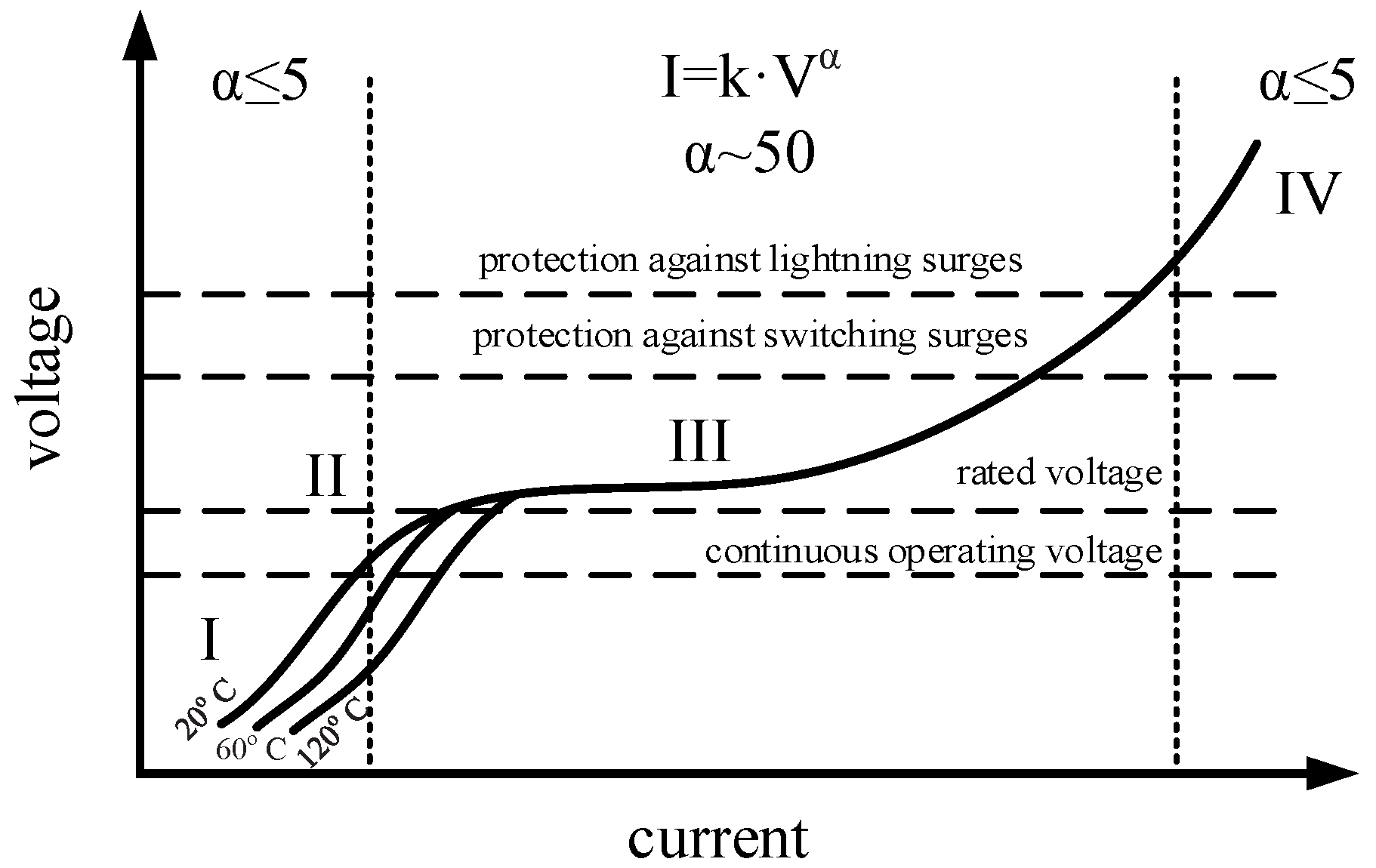
  • I is the discharge current that passes through the arrester,
  • k is a measure of its current-carrying capacity depending on geometrical configuration and characteristics of the arrester (cross-sectional area, length),
  • V is the residual voltage at the terminals of the arrester, and
  • α is a measure of non-linearity between V and I, depending on the composition of the oxides.
Figure 1 depicts the voltage-current characteristic of a ZnO resistor. The non-linear resistor offers a path of low impedance between the phase conductor and the earth, diverting the incoming overvoltage to the grounding system. The discharge current that passes through the arrester to the grounding system restricts the residual voltage across the arrester and, therefore, the arising voltage level at the equipment and the system connected to it. During normal operation of the system, the arrester presents a high impedance, providing a near-open circuit. It remains so until a surge voltage happens, and is restored immediately after discharge of the excess overvoltage [1].
Figure 2 depicts the basic ZnO non-frequency-dependent element, where the total leakage current has a capacitive and a resistive component. Values L and C represent the inductance of the conducting leads, and the capacitance between the external insulation and the ZnO block, respectively. The non-linear resistor presents high value (A0) for low currents, as low-value bulk resistance (RB) is the dominant component for high current levels [9,10,14,23].
However, the above model is not suitable for lightning performance analysis, considering that the response of the arresters is different in the case of fast disturbances [18]. Metal oxide gapless arresters respond in a different way to several types of injected overvoltages, depending on the magnitude and the duration of the surge. The most used frequency-dependent circuit models that satisfy the dynamic behavior of the modern arresters are presented in detail in [8,9,13]. These models differ in the procedure for the computation of their parameters, but all are appropriate for lightning performance studies. Note that the Pinceti–Giannettoni and Fernandez–Diaz models rely on the IEEE model [8]. However, they use the electrical characteristic data provided by the datasheet of manufacturers instead of the geometrical characteristics that the IEEE model uses.
The IEEE model [8] (Figure 3) includes the non-linear resistors A0 and A1 and a filter R-L. The voltage–current characteristics of A0 and A1 are illustrated in Figure 4. For currents with high rising times, the filter R-L presents a low impedance, resulting in a parallel connection between A0 and A1. For impulse currents with low rising times, the filter R-L presents a high impedance, diverting the current to A0.
The Pinceti–Giannettoni model [9] compared with the IEEE model does not have any capacitance, since R0 and R1 give their place to the resistance R0 (Figure 5). A0 and A1 obey the V–I characteristics of Figure 4.
In the Fernandez–Diaz model [13], A0 and A1 are separated only by the inductance L1, the estimation of which is performed according to the procedure described in [13] (Figure 6).

3. Definition and Analysis of the Optimization Problem

The circuit models of Section 2 consist of various parameters that formulate a column vector x:
  • x = [R0, R1, L0, L1, C]T for the IEEE model [8]
  • x = [R0, L0, L1]T for the Pianceti–Giannettoni model [9]
  • x = [R0, L1, C]T for the Fernandez–Diaz model [13].
The outcomes of each model for each current impulse must be compared with the datasheet values. The residual voltage of a model can be accurately evaluated if an adequate selection of its parameters x = (x1, x2, …, xn)T is carried out. Considering the great impact of the parameter values of each model on the accuracy of the simulated results, the following objective function must be minimized:
e = i = 1 m | V res , s ( x ) I i V res , m ( x ) I i V res , m ( x ) I i | + | E s ( x ) I i E m ( x ) I i E m ( x ) I i |
where
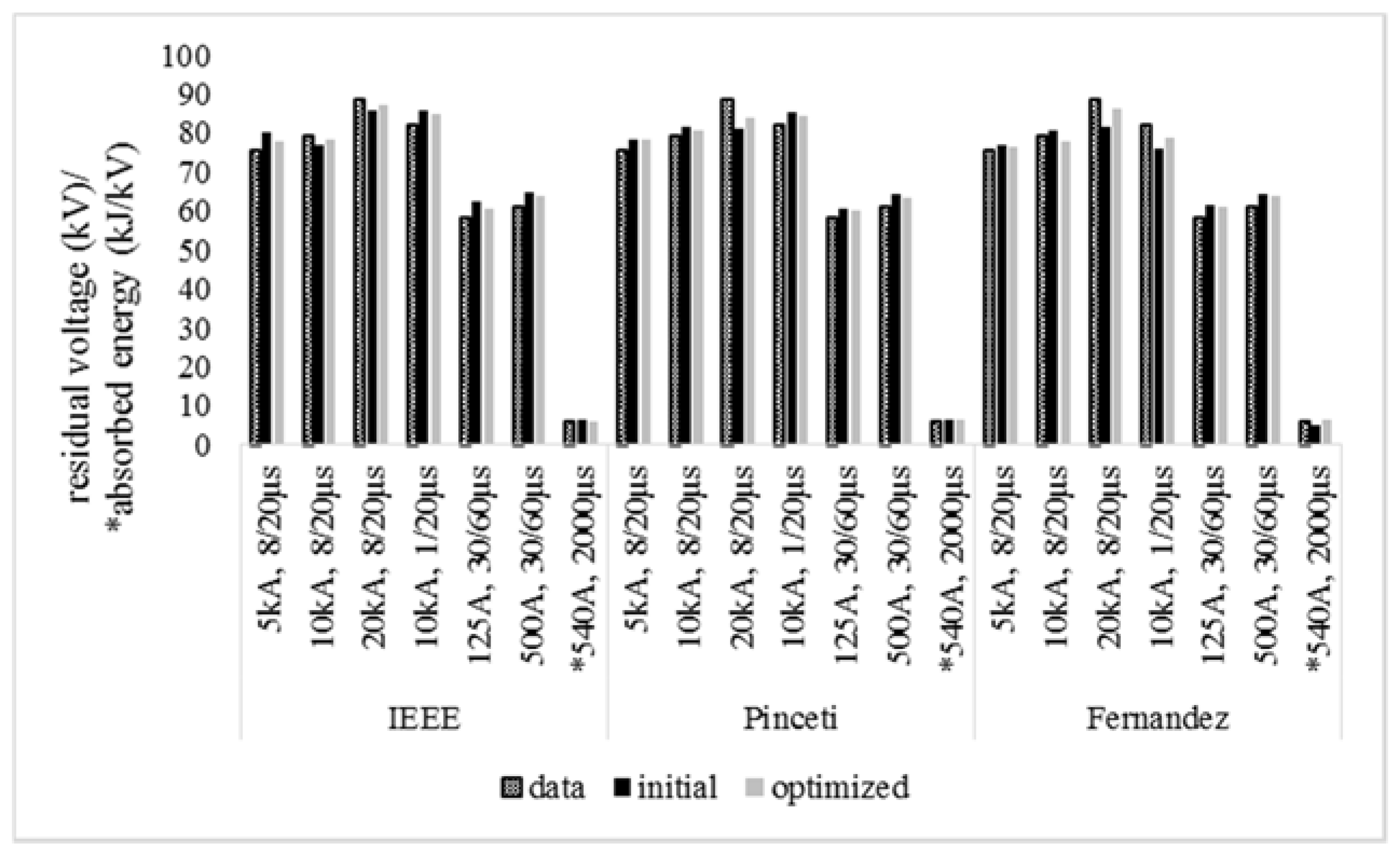
  • Vres is the magnitude of the residual voltage of the arrester,
  • s is an indicator for the results obtained by simulation procedures,
  • m is an indicator for the data provided by the manufacturer,
  • I is the injected impulse current (peak value, time),
  • i is an indicator that corresponds to the curve of the injected impulse current (i = 1: 8/20 μs, i = 2: 1/20 μs, i = 3: 30/60 μs, i = 4: long duration impulse),
  • E is the absorbed energy by the arrester in Joules, given as following:
    E = 0 T u ( t ) · i ( t ) dt
where
  • u(t) is the waveform of the residual voltage of the arrester,
  • i(t) is the waveform of the discharge current that passes through the arrester, and
  • is the duration of the injected impulse current.
Note that surge arresters have to withstand the energy discharged by the atmospheric surge. This energy is directly affected by the lightning hit position, the waveform of the lightning current, and the grounding resistance [25]. If the absorbed energy is greater that the withstand capability of the device, the arrester is damaged.
The implementation of an optimization procedure will adjust the optimal values xi. The aim of the optimization procedure is to minimize Equation (2), which is a function of several variables. It is infeasible to attain the optimum procedure in a single step, but instead an iteration technique is required. In the current work, the harmony search method (presented in Section 4) is applied.

4. Harmony Search Method

The minimization of the objective function (Equation (2)) is performed by applying the harmony search method [26]. This population-based meta-heuristic algorithm searches for the optimum solution by trying various combinations of the variables, mimicking the music improvisation process. In contrast to other similar procedures, harmony search methodology uses two different operators, i.e., the harmony memory considering rate (HMCR,) and the pitch adjusting rate (PAR). These generate and mutate the solution, correspondingly. It is worth mentioning that HMCR and PAR control the component of solutions and determine the convergence rate [27,28,29,30,31].
Considering an objective function f(x), x ∈ Xi, i = 1, 2, …, n, where
  • x is the set of each decision variable xi,
  • n is the number of decision variables,
  • Xi is the set of the possible range of values for each decision variable, considering lower and upper bounds for each decision variable.
The harmony search method includes the following steps [26,32,33]:
Step 1: Initialization of the harmony search memory (HM). Considering an n-dimension problem, HM is given as
HM = [ x 1 1 x n 1 x 1 HMS x n HMS ]
where
  • x i j are randomly generated solutions,
  • HMS is the harmony memory size,
  • i = 1, 2, …, n, and
  • j = 1, 2, …, HMS
Step 2: Improvisation of a new solution from the HM based on the HMCR, i.e., the probability that a solution is selected from the current HM members. The solution x i j is mutated according to the PAR.
Step 3: Update HM. In the case that the solution obtained from step 2 achieves a better convergence of the objective function compared with the worst member of the HM, then this new solution replaces the existing one in the HM.
Step 4: Repeat steps 2 and 3 until the defined criterion is satisfied.

5. Results and Discussion

Table 1 presents the electrical and geometrical characteristics of the arrester under examination. Based on these data, the initial values of the parameters of each model are computed (Table 2) according to the procedures presented briefly in Section 2. By using the harmony method, the optimum parameters that minimize Equation (2) are evaluated, considering the following cases:
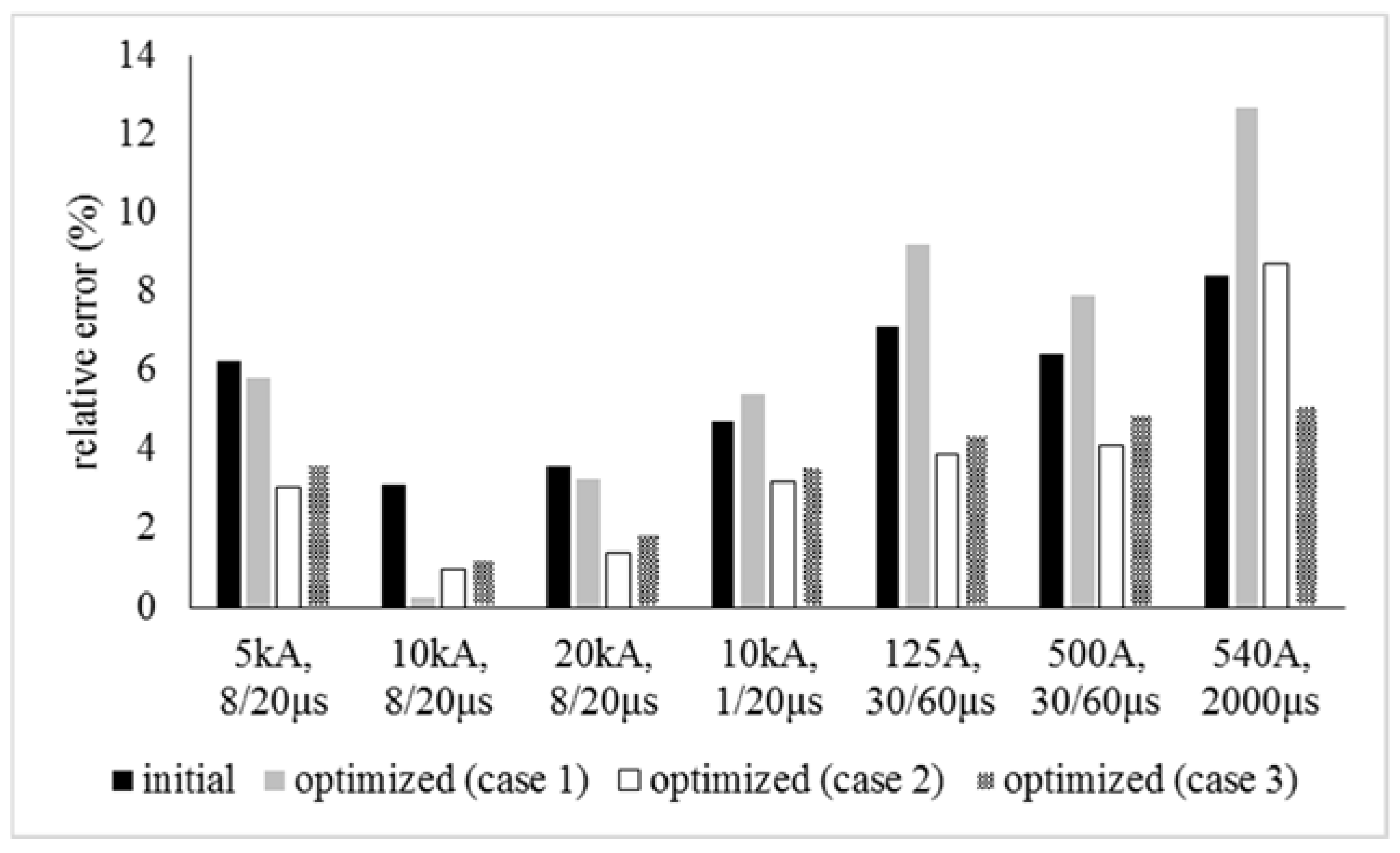
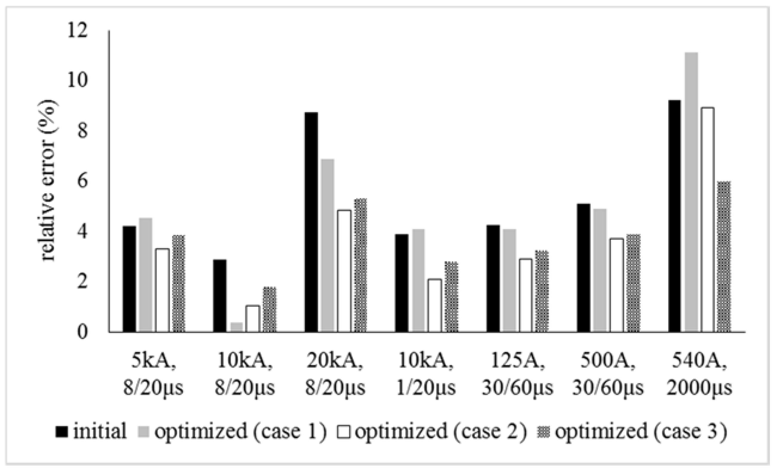
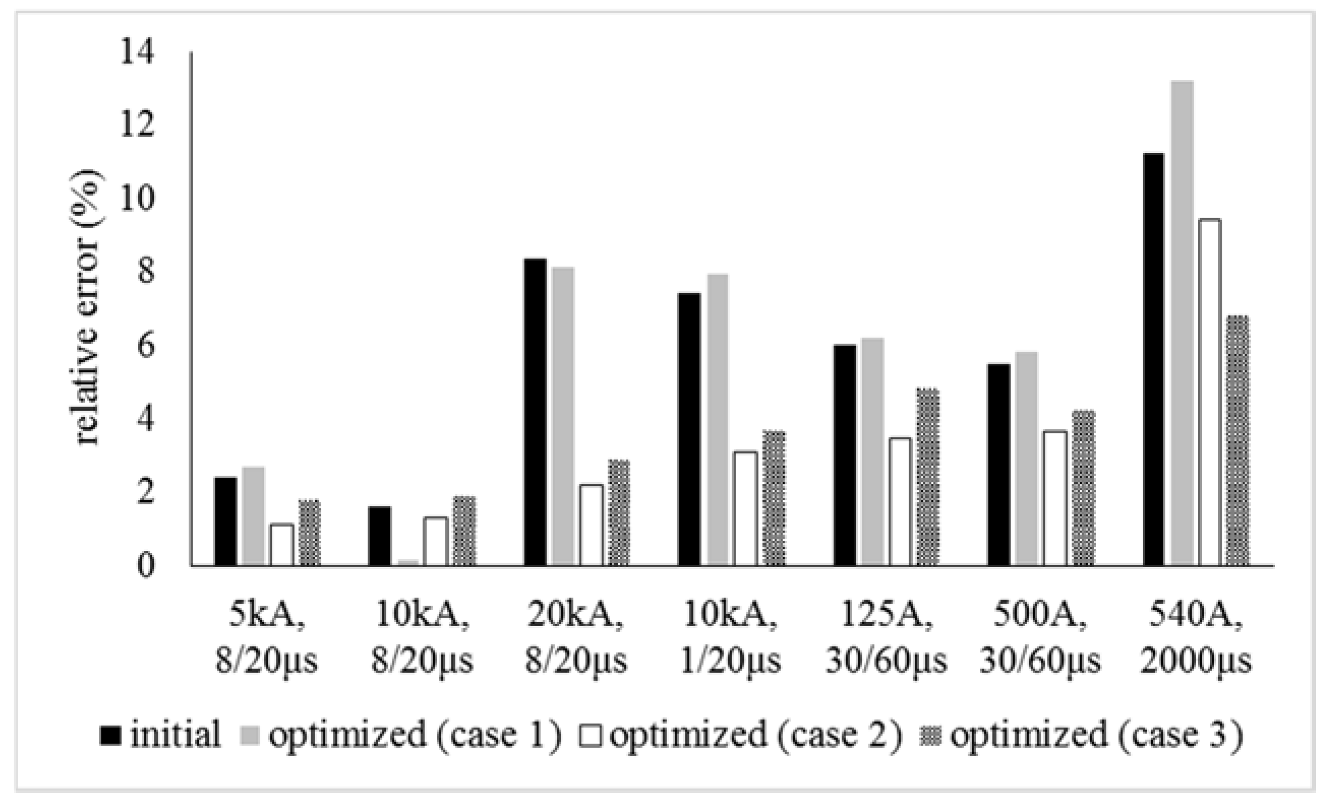
  • Case 1: implementation of the algorithm considering the response for a 10 kA, 8/20 μs current.
  • Case 2: implementation of the algorithm considering the response for all the current waveforms of Table 1.
  • Case 3: implementation of the algorithm considering the response for all the current curves and the energy for long duration impulse of Table 1.
It is worth mentioning that the state equation of each model is solved according to the procedure presented in [17] by using a suitable software.
The optimum parameters of each model and for each case are presented in Table 2. The outcomes of the optimization algorithm are used to compute the residual voltage and the absorbed energy. Figure 7, Figure 8 and Figure 9 present the relative errors of the theoretical results, implementing the initial values of the parameters according to [8,9,13], and those extracted from the harmony search method for the three examined cases. The outcomes of Case 1 almost eliminate the relative error for a 10 kA, 8/20 μs impulse current, but may worsen the response of each model for the other examined waveforms. Case 2 gives very good results for the peak value of the residual voltage for all the injected currents, but seems to be ineffective as far as the absorbed energy is concerned. Ultimately, the results of Case 3 seem to improve the behavior of each model for all the lightning/switching currents and the energy for a long duration impulse current.
Figure 10 provides the absolute values for Case 3. The accuracy of the obtained results and the adequate convergence between the theoretical calculations and the manufacturer’s data play a fundamental role in the lightning performance and insulation coordination studies. These factors allow the study to avoid imprecise estimations that lead to the inappropriate design of the power systems. The presented outcomes in Figure 10 indicate that the harmony search method improves the precision of each model compared with those obtained by the implementation of the initial values of the parameters. So, the applied methodology is proven to be a sophisticated technique that meets the demands for adequate representations of the dynamic behavior of modern arresters, and the extracted results support this claim.
Added to the above analysis, the outcomes of the harmony search algorithm are compared with results obtained from methodologies presented in previous works [15,16,17], i.e., the downhill simplex method [15], the Powell method [16] and a genetic algorithm (GA) [17] (Table 3). In Cases 2 and 3, the simplex and the Powell methods cannot be successfully applied, since both are trapped in local minima. The harmony search method and the genetic algorithm are appropriate for the objective function defined in Cases 2 and 3, resulting in adequate predictions. Compared with the genetic algorithm, the harmony search method does not present characteristics of algorithm complexity, since it does not need any prior domain information, but only uses a single search memory to evolve.

6. Conclusions

The efficient circuit modeling of metal oxide gapless surge arresters and the identification of their parameters are critical matters for lightning performance and insulation coordination studies. The main point of concern in the modeling of gapless arresters is the evaluation of the parameters of the circuit models, which are dependent on their geometrical and electrical characteristics. In this work, the harmony search method is used to estimate the optimum parameters of the most frequently used models, in an effort to minimize the difference between simulation results and the manufacturer’s data. The method provides adequate outcomes, considering an extensive range of parameter values without being restricted to local minima. This compares favorably with other conventional optimization techniques, where the optimum solution is heavily influenced by the initial values. The applied method investigates the potential combinations of the parameters, providing the most suitable solution that optimizes the defined objective function. The proposed method is applied to a medium voltage arrester, examining three different cases. The outcomes of the harmony search method are also compared with results obtained from other methodologies used in previous works, highlighting the efficiency of the applied technique. Moreover, the obtained results reveal that the accuracy of the extracted outcomes of each model is influenced by the determination of the objective function. Indeed, consideration of all the available current waveforms and the absorbed energy results in more precise predictions of each model for a range of impulse current waveforms. In conclusion, the proposed algorithm can definitively contribute to the improvement of the accuracy and the reliability of the lightning performance studies.

Author Contributions

Christos A. Christodoulou and Vasiliki Vita conceived the idea and led the whole work; Georgios Perantzakis and Lambros Ekonomou performed the simulations; Christos A. Christodoulou, George Milushev and Vasiliki Vita analyzed the data; Georgios Perantzakis contributed required material; George Milushev and Lambros Ekonomou wrote the paper.

Conflicts of Interest

The authors declare no conflict of interest.

References

  1. Agrawal, K.C. Electrical Power Engineering: Reference and Applications Handbook; CRC Press: Boca Raton, FL, USA, 2007. [Google Scholar]
  2. Laughton, M.A.; Warne, J. Electrical Engineer’s Reference Book, 16th ed.; Newnes: Amsterdam, The Netherlands, 2003. [Google Scholar]
  3. Christodoulou, C.A.; Vita, V.; Maris, T.I. Lightning protection of distribution substations by using metal oxide gapless surge arresters connected in parallel. Int. J. Power Energy Res. 2017, 1, 1–7. [Google Scholar] [CrossRef]
  4. Tarchini, J.A.; Gimenez, W. Line surge arrester selection to improve lightning performance of transmission lines. In Proceedings of the IEEE PowerTech Conference, Bologna, Italy, 23–26 June 2003. [Google Scholar]
  5. Christodoulou, C.A.; Ekonomou, L.; Fotis, G.P.; Gonos, I.F.; Stathopulos, I.A. Assessment of surge arrester failure rate and application studies in Hellenic high voltage transmission lines. Electr. Power Syst. Res. 2010, 80, 176–183. [Google Scholar] [CrossRef]
  6. IEEE. IEEE Std 1243-1997: IEEE Guide for Improving the Lightning Performance of Transmission Lines; IEEE: New York, NY, USA, 1997. [Google Scholar]
  7. IEC. IEC 60099-4: Surge Arresters-Part 4: Metal-Oxide Surge Arresters without Gaps for a.c. Systems, 2nd ed.; IEC: Geneva, Switzerland, 2004–2005.
  8. IEEE Working Group 3.4.11. Modeling of metal oxide surge arresters. IEEE Trans. Power Deliv. 1992, 7, 302–309.
  9. Pinceti, P.; Giannettoni, M. A simplified model for zinc oxide surge arresters. IEEE Trans. Power Deliv. 1999, 14, 393–398. [Google Scholar] [CrossRef]
  10. Ceaki, O.; Seritan, G.; Vatu, R.; Mancasi, M. Analysis of power quality improvement in smart grids. In Proceedings of the 10th International Symposium on Advanced Topics in Electrical Engineering (ATEE), Bucharest, Romania, 23–25 March 2017; pp. 797–801. [Google Scholar] [CrossRef]
  11. Nieto, A.; Vita, V.; Maris, T.I. Power quality improvement in power grids with the integration of energy storage systems. Int. J. Eng. Res. Technol. 2016, 5, 438–443. [Google Scholar]
  12. Ceaki, O.; Vatu, R.; Mancasi, M.; Porumb, R.; Seritan, G. Analysis of electromagnetic disturbances for grid-connected PV. In Proceedings of the 5th International Conference on Modern Electric Power Systems (MEPS2015), Poland, Wroclaw, 6–9 July 2015. [Google Scholar] [CrossRef]
  13. Fernandez, F.; Diaz, R. Metal oxide surge arrester model for fast transient simulations. In Proceedings of the International Conference on Power System Transients IPAT’01, Rio De Janeiro, Brazil, 24–26 June 2001. [Google Scholar]
  14. Bayadi, A.; Harid, N.; Zehar, K.; Belkhiat, S. Simulation of metal oxide surge arrester dynamic behavior under fast transients. In Proceedings of the International Conference on Power Systems Transients 2003, New Orleans, LA, USA, 28 September–2 October 2003. [Google Scholar]
  15. Christodoulou, C.A.; Ekonomou, L.; Fotis, G.P.; Karampelas, P.; Stathopulos, I.A. Parameters’ optimisation for surge arrester circuit models. IET Sci. Meas. Technol. 2010, 4, 86–92. [Google Scholar] [CrossRef]
  16. Christodoulou, C.A.; Vita, V.; Ekonomou, L.; Chatzarakis, G.E.; Stathopulos, I.A. Application of Powell’s optimization method to surge arrester circuit models’ parameters. Energy J. 2010, 35, 3375–3380. [Google Scholar] [CrossRef]
  17. Christodoulou, C.A.; Gonos, I.F.; Stathopulos, I.A. Estimation of the parameters of metal oxide gapless surge arrester equivalent circuit models using genetic algorithm. Electr. Power Syst. Res. 2011, 81, 1881–1886. [Google Scholar] [CrossRef]
  18. Bayadi, A. Parameter identification of ZnO surge arrester models based on genetic algorithms. Electr. Power Syst. Res. 2008, 78, 1204–1209. [Google Scholar] [CrossRef]
  19. Nafar, M.; Gharehpetian, G.B.; Niknam, T. Improvement of estimation of surge arrester parameters by using modified particle swarm optimization. Energy 2011, 36, 4848–4854. [Google Scholar] [CrossRef]
  20. Lira, G.R.S.; Fernandes, D.; Costa, E.G. Parameter identification technique for a dynamic metal-oxide surge arrester model. In Proceedings of the International Conference on Power Systems Transients (IPST2009), Kyoto, Japan, 2–6 June 2009. [Google Scholar]
  21. Li, H.J.; Birlasekaran, S.; Choi, S.S. A parameter identification technique for metal-oxide surge arrester models. IEEE Trans. Power Deliv. 2002, 17, 736–741. [Google Scholar] [CrossRef]
  22. ABB: High Voltage Surge Arresters, 5th ed.; ABB: Baden, Switzerland, 2004–2010.
  23. Suljanovic, N.; Mujcic, A.; Murko, V. Practical issues of metal-oxide varistor modeling for numerical simulations. In Proceedings of the 28th International Conference on Lightning Protection, Kazanawa, Japan, 18–22 September 2006; pp. 1149–1154. [Google Scholar]
  24. Hinrichsen, V. Metal-Oxide Surge Arresters in High Voltage Power Systems, 3rd ed.; Siemens: Munich, Germany, 2011. [Google Scholar]
  25. Christodoulou, C.A.; Ekonomou, L.; Mitropoulou, A.D.; Vita, V.; Stathopulos, I.A. Surge arresters’ circuit models review and their application to a Hellenic 150 kV transmission line. Simul. Model. Pract. Theory 2010, 18, 836–849. [Google Scholar] [CrossRef]
  26. Wang, X.; Gao, X.Z.; Zenger, K. An Introduction to Harmony Search Optimization Method; Springer Briefs in Computational Intelligence; Springer: Berlin/Heidelberg, Germany, 2015. [Google Scholar]
  27. Omran, M.G.H.; Mahdavi, M. Global-best harmony search. Appl. Math. Comput. 2008, 198, 643–656. [Google Scholar] [CrossRef]
  28. Lee, K.S.; Geem, Z.W. A new meta-heuristic algorithm for continuous engineering optimization: Harmony search theory and practice. Comput. Methods Appl. Mech. Eng. 2005, 194, 3902–3933. [Google Scholar] [CrossRef]
  29. Engelbrecht, A.P. Fundamentals of Computational Swarm Intelligence; Wiley: Hoboken, NJ, USA, 2005. [Google Scholar]
  30. Lin, C.J.; Wang, J.G.; Chen, S.M. 2D/3D face recognition using neural network based on hybrid Taguchi-particle swarm optimization. Int. J. Innov. Comput. Inf. Control 2011, 7, 537–553. [Google Scholar]
  31. Cai, X.; Cui, Z.; Zeng, J.; Tan, Y. Particle swarm optimization with self-adjusting cognitive selection strategy. Int. J. Innov. Comput. Inf. Control 2008, 4, 943–952. [Google Scholar]
  32. Lee, K.S.; Geem, Z.W. A new structural optimization method based on the harmony search algorithm. Comput. Struct. 2004, 82, 781–798. [Google Scholar] [CrossRef]
  33. Mahdavi, M.; Fesanghary, M.; Damangir, E. An improved harmony search algorithm for solving optimization problems. Appl. Math. Comput. 2007, 188, 1567–1579. [Google Scholar] [CrossRef]
Figure 1. V–I characteristic of a typical metal oxide arrester (I: capacitive linear area, current ≤ 1 mA; II: knee point, transition from the almost-insulating to the conducting condition; III: intensely non-linear area; IV: ohmic area, high current area) [23,24].
Energies 10 02168 g001
Figure 2. Basic ZnO element model [1,9].
Energies 10 02168 g002
Figure 3. The IEEE model [8] (d is the height of the arrester in m, n is the number of varistor columns).
Energies 10 02168 g003
Figure 4. Voltage–current characteristics of the non-linear resistances A0 and A1 [8].
Energies 10 02168 g004
Figure 5. The Pinceti–Giannettoni model (Vn is the arrester’s rated voltage, Vr8/20 is the residual voltage for an 8/20 10 kA impulse current and Vr1/T2 is the residual voltage for a 1/T2 10 kA impulse current) [9].
Energies 10 02168 g005
Figure 6. The Fernandez–Diaz model [13].
Energies 10 02168 g006
Figure 7. Results for the IEEE model.
Energies 10 02168 g007
Figure 8. Results for the Pinceti–Giannettoni model.
Energies 10 02168 g008
Figure 9. Results for the Fernandez–Diaz model.
Energies 10 02168 g009
Figure 10. Residual voltage (in kV) and dissipated energy (in kJ/kV) for the three examined models (case 3) (the symbol * corresponds to the absorbed energy by the arresters).
Energies 10 02168 g010
Table 1. Characteristics of the arrester under study.
Rated Voltage (Ur)30 kV
Maximum Continuous Operating Voltage (Uc)24 kV
Nominal Discharge Current10 kA
Line Discharge Class according to IEC 60099-42
Long Duration Current Impulse (2000 μs)540 A
Energy for Long Duration Impulse5.8 kJ/kV Uc
Residual Voltage8/20 μs5 kA75.29 kV
10 kA79.27 kV
20 kA88.78 kV
1/20 μs10 kA82.01 kV
30/60 μs125 A58.14 kV
500 A61.02 kV
Sheds11
Height302 mm
Creepage762 mm
Table 2. Initial and optimized parameters for each model and each case.
IEEE Model [8]Pinceti–Giannettoni Model [9]Fernandez–Diaz Model [13]
InitialOptimizedInitialOptimizedInitialOptimized
CaseCaseCase
123123123
R0 (Ω)30.2017.8294.8154.191 × 10610.952 × 1061.102 × 1061 × 1060.998 × 1061.051 × 1061.088 × 106
R1 (Ω)19.6324.4827.8837.54--------
L0 (μΗ)0.06040.1080.1410.4210.2590.1920.3140.419----
L1 (μΗ)4.5302.4701.9822.2170.0860.0570.0280.0410.6300.5870.6810.701
C (pF)331.1784.2860.91008.1----334.4481.2287.7398.4
Table 3. Comparison of the harmony search method, downhill simplex method [15], Powell method [16] and genetic algorithm [17]: relative error (%) between simulation results and manufacturer’s data.
5 kA
8/20 μs
10 kA
8/20 μs
20 kA
8/20 μs
10 kA
1/20 μs
125 A
30/60 μs
500 A
30/60 μs
540 A
2000 μs
IEEE Model [8]initial6.223.13.584.777.196.418.4
Optimized (Case 1)Harmony5.840.253.275.419.247.9012.7
Simplex6.810.664.25.209.518.3811.4
Powell6.940.724.475.6110.18.8413.1
GA5.950.373.415.279.836.9811.9
Optimized (Case 2)Harmony3.040.971.43.23.94.128.70
Simplextrapped in local minima
Powelltrapped in local minima
GA3.241.191.383.464.214.409.45
Optimized (Case 3)Harmony3.651.211.853.584.424.875.10
Simplextrapped in local minima
Powelltrapped in local minima
GA4.031.582.243.925.105.515.95
Pinceti–Giannettoni Model [9]initial4.212.878.743.874.245.089.2
Optimized (Case 1)Harmony4.520.356.894.104.214.8911.1
Simplex4.910.507.084.745.586.2412.9
Powell4.640.416.724.675.145.7812.2
GA4.810.626.714.734.955.3212.6
Optimized (Case 2)Harmony3.311.044.842.12.913.708.91
Simplextrapped in local minima
Powelltrapped in local minima
GA3.681.414.582.433.084.129.21
Optimized (Case 3)Harmony3.841.775.302.783.253.876.04
Simplextrapped in local minima
Powelltrapped in local minima
GA4.092.165.123.224.104.156.59
Fernandez–Diaz model [13]initial2.411.598.357.415.975.4511.23
Optimized (Case 1)Harmony2.710.158.17.886.205.8113.2
Simplex3.550.418.298.316.546.7715.1
Powell3.290.378.158.046.316.2812.2
GA2.940.307.827.946.485.5911.7
Optimized (case 2)Harmony1.11.312.213.083.453.649.4
Simplextrapped in local minima
Powelltrapped in local minima
GA1.541.922.733.503.684.0110.7
Optimized (case 3)Harmony1.771.912.893.714.814.196.81
Simplextrapped in local minima
Powelltrapped in local minima
GA1.952.243.114.024.614.426.40

