Abstract
Sustainable energy-based generation systems, such as photovoltaic and wind turbine generation systems, normally adopt inverters to connect to the grid. These power electronic interfaces possess the characteristics of small inertia and small output impedance, which create difficulties to stabilize the voltage and frequency of a distributed power source. To deal with this problem, a Virtual Synchronous Generator (VSG)-based inverter control method is presented in this paper by introducing virtual inertia and damping coefficient into the control loop to emulate the dynamic behavior of a traditional synchronous generator. Based on this VSG control method, a three-layer hierarchical control scheme is further proposed to increase the control accuracy of the voltage and frequency in a VSG-based distributed generation system with parallel inverters. The principle of the VSG control method, the system stability analysis, the design process of the hierarchical control structure, and the frequency/voltage secondary regulation processes are all specified in this paper. Finally, some numerical simulations are carried out and the effectiveness of proposed control scheme is verified by the simulation results analysis.
1. Introduction
In recent years, with the development and utilization of sustainable energy, the concepts of Distributed Energy Resources (DERs), such as photovoltaics and wind turbines, and microgrids, a collection of Distributed Generators (DGs), converters, storages, and loads, are attracting more and more attentions [1]. However, the DERs usually output power through converters, and this kind of power electronic interfaces have characteristics which distinguish them from traditional Synchronous Generator (SG)-based power sources, such as small inertia, fast response time, and difficultly stabilized output voltage and frequency [2]. Because of the increasing penetration of DERs in the power grid nowadays, these characteristics raise new control challenges for microgrids [3], and consequently, have drawn the attention of many researchers.
A SG, being the key component in a conventional generation system, possesses properties such as larger moment of inertia, large output impedance and good drooping control characteristics. If part of these features can be introduced to a DG, some interesting methods can be adopted for the voltage and frequency stability control of a microgrid.
Accordingly, to overcome the shortcomings introduced by the power electronic interfaces in a microgrid and to refer to the control ideas of classical generation systems, the concept of virtual synchronous generator has been proposed [4,5,6,7,8,9,10,11,12].
Some related research work can be found in the literature. The concept of a static synchronous generator based on Park’s transformation and the swing equation is proposed in [4]. In [5], the inertial dynamics of a virtual-synchronous-controlled doubly fed induction generator were proposed to make the wind turbine provide the desired inertial support to the power grid. The VSG system addressed in [6] is designed to connect an energy storage unit to the main grid. In [7], a VSG controller is proposed by using the swing equation of a DER with the purpose of generating the inverter frequency reference. Arani et al. [8] describes the design of a virtual inertia method, which imitates the kinetic inertia of synchronous generator, to improve the system dynamic behavior of wind power generation. In [9], an inertia element is introduced into the frequency-power droop to determine the command reference of the frequency in a synchronous generator emulation control strategy for a voltage source converter. Paquette et al. [10] applies a virtual impedance for current limiting of voltage-controlled inverters during overloads caused by poor transient load sharing between inverters and synchronous generators in islanded microgrids. In [11], the dynamic characteristics of VSG is studied with comparison with the droop control in both stand-alone mode and synchronous-generator-connected mode. Wu et al. [12] focuses on the small-signal modeling and parameters design of the power loop of the VSG control, and points out that the bandwidth of the power loop should be far less than twice the line frequency for the purpose of avoiding the VSG output voltage to be severely distorted.
The above research work is illuminating and their achievements suggest new ideas for emulating the dynamic behavior of a conventional SG in the control loop of an inverter, which can help us stabilize the output frequency and voltage of a DG. However, even for the VSG control method, there are some drawbacks, such as static errors that exist in both the frequency and voltage outputs, and when parallel inverters are considered, because the VSG is a distributed control method and only local electrical parameters are collected for its control loops, it is not easy to distribute the overall active and reactive power demand among all the parallel DGs in an equitable way, especially when there is a load switching.
To deal with the above problems, the research presented in this paper, which extends the work of [13], mainly focuses on a VSG-based hierarchical control scheme for distributed generation systems. The hierarchical control theory is widely used in traditional power systems and now is introduced in microgrids for its frequency and voltage control, power quality improvements, and multiagent system organization. For example, Dou et al. [14] proposed a multi-agent-based hierarchical hybrid control scheme to maintain secure voltages as well as maximize economic and environmental benefits. Mojica-Nava et al. [15] presented a hierarchical microgrid management system using an evolutionary game theory-based dispatch strategy to integrate the three main control levels needed for microgrid operation. In [16], an enhanced hierarchical control structure with multiple current loop damping schemes was put forward for an islanded microgrid control. Feng et al. [17] proposed an active, unbalanced, and harmonic grid-connected current suppression strategy based on hierarchical theory for a grid-connected microgrid. A comprehensive hybrid agent framework with the considerations of the different physical agents’ standards was presented and validated in a microgrid setup [18]. All these research works are heuristic and represent important foundations for future research on intelligent hierarchical control of microgrids.
To illustrate the proposed VSG-based hierarchical control method, this paper is organized in the following way: firstly, a VSG-based inverter control method is presented in Section 2. This method is deduced from the rotator swing equation and the stator electrical equation of a SG. The design process of the virtual governor and virtual excitation regulator, and the system stability analysis are presented in detail. Then, a hierarchical control scheme of the parallel inverters is designed in Section 3. The architecture of this three-layer control system, and the principles of frequency and voltage hierarchical control in the island mode are discussed in this section. In Section 4, a simulation platform has been built up with MATLAB/Simulink (2014a, MathWorks, Natick, MA, USA) to validate the effects of VSG control method of a single inverter and the VSG based hierarchical control of parallel inverters. Finally, the conclusions of the paper are put forth in Section 5.
2. The VSG-Based Inverter Control
2.1. System Structure of VSG-Based Control
The system structure of the proposed VSG-based inverter control scheme is illustrated in Figure 1.
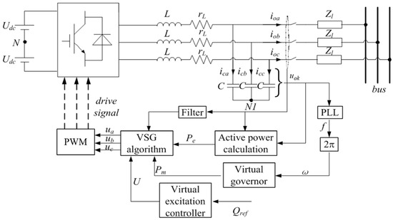
Figure 1.
System structure of the proposed VSG-based inverter controller.
In Figure 1, L and C are the filter inductor and capacitor, respectively; rL is the equivalent resistance of filter inductors, switches, wiring and other components; k stands for a, b and c phases; uok is output voltage of the inverter; Zl is the equivalent line impedance.
The mathematic model of the three-phase full-bridge inverter in Figure 1 after Laplace transform to the frequency domain is:
where Umk is the voltage reference; G(s) is the transfer function of the output voltage transformed to modulating wave; Zo(s) is the equivalent output impedance; Kpwm = Udc/Umk is the equivalent gain of the pulse width modulation; and s is the complex variable of the frequency domain.
Uok (s) = G(s)Umk (s) − Zo (s) Iok (s)
The equivalent block diagram of the main circuit is shown in Figure 2.
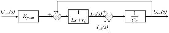
Figure 2.
Main circuit block diagram.
2.2. VSG-Based Control Algorithm
Take a non-salient pole SG as reference with the number of pole pairs equal to 1 and ignoring its damper windings, eddy current losses and magnetic saturation. The synchronous machine’s second-order mathematical model is adopted and described as follows [19]:
where Tm and Te are the mechanical torque of SG rotor shaft input from a prime mover and the electromagnetic torque of stator, respectively; D is the damping coefficient used to represent the damping characteristics of the prime mover. Δω = ω − ωB, where ω is the actual electrical angular velocity and ωB is the rated value. When the number of pole pairs is 1, the mechanical angular velocity ωm = ω; Pm and Pe are the mechanical power and electromagnetic power, respectively; J and θ are the rotational inertia and electrical angle; E is the three-phase stator winding inductive electromotive force; U and I are the stator terminal voltage and current respectively; and the dot above these three parameters, E, U and I, represent their phasor form; Rt and Xt are the resistance and reactance of the stator armature, respectively.
According to Equation (4), the block diagram of VSG control scheme can be deduced and illustrated in Figure 3.
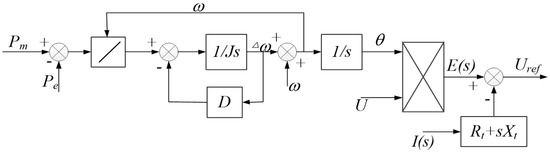
Figure 3.
Block diagram of VSG control algorithm.
From Equation (4) and Figure 3, an impedance parameter can be introduced to the system by measuring the output current of the main circuit. The output impedance of a SG can be emulated by subtracting the voltage of this impedance from the excitation inductive electromotive force. According to the stator electrical equations of a SG, the calculation of synchronous reactance voltage drops needs to calculate the current differential, and thus introduce harmonic component of current to stator voltages uabc. The quantity of harmonic component will increase after PWM modulation. Hence, the sampling current should be filtered.
2.3. Virtual Speed Regulator Design
For a diesel engine synchronous generator set, when the speed regulation system is operating in stable state, we have [20]:
where ωref and ω are, respectively, the reference angular frequency and actual angular frequency of the diesel engine synchronous generator set; P means active power and the subscript ref represents its reference value; Kω is the rate of power-frequency characteristic of the synchronous generator; Δ means the incremental of the corresponding parameters; and R is the frequency difference coefficient.
(ωref − ω)Kω + (Pref − P) = 0
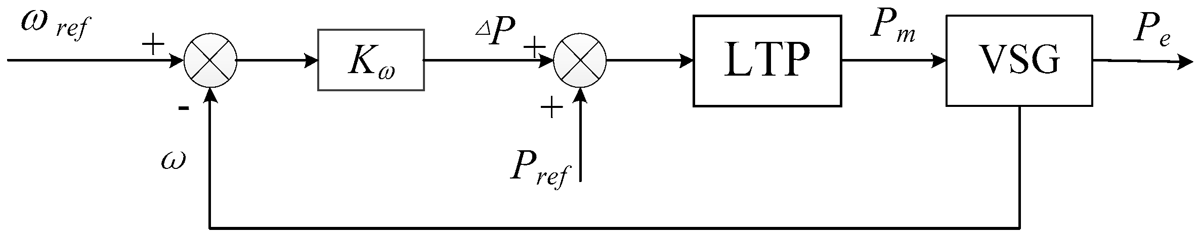
To emulate the classical speed regulation, according to Equation (5), the control block diagram of the VSG governor can be obtained and shown in Figure 4.
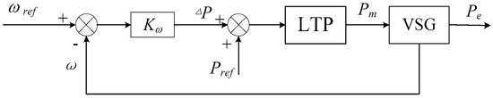
Figure 4.
Control block diagram of the VSG governor.
In Figure 4, Pm and Pe are the mechanical power and electromagnetic power respectively; and LTP represents the power limiter used to limit the mechanical power input to the VSG.
From Figure 4, the error between the reference angular frequency ωref and the VSG angular frequency output ω is the input of a proportional controller to control the input mechanical power. Scheduling power Pref is introduced to the VSG governor to reduce the range of the frequency of feedback control.
In a stable state, the mechanical power is equal to the electromagnetic power:
(ωref − ω)Kω + Pref = Pm = Pe
Compared with Equations (5) and (7) shows a similar power frequency characteristic of a synchronous machine.
2.4. Virtual Excitation System Design
When the output reactive current changes, the excitation current should be controlled by a regulator to keep the terminal voltage at the rated value. According to the principle of a SG [21]:
where E and U are the excitation of electromotive force and stator terminal voltage, respectively; IQ and Xt are the reactive current and synchronous reactance, respectively; δ is power angle, and normally being small, hence, cosδ ≈ 1 and Equation (8) can be simplified as follows:
Let Mf denote the mutual inductance of the stator windings, and if the excitation current. The amplitude of excitation electromotive force can be expressed as:
Assume that UB is the base value of stator voltage and ifB is the base value of excitation current, the excitation electromotive force and excitation current can be expressed in per unit as follows:
where the superscript symbol “*” means the quantity is in per unit.
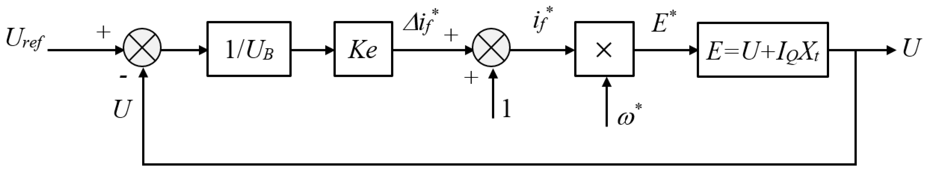
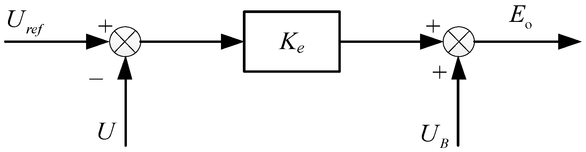
The exciting winding of VSG is a controllable current source instead of a controllable voltage source, which differs from a synchronous generation system. The VSG excitation regulator can directly control excitation current to stabilize the terminal voltage. According to Equations (11) and (12), the block diagram of a virtual excitation regulator can be illustrated in Figure 5.
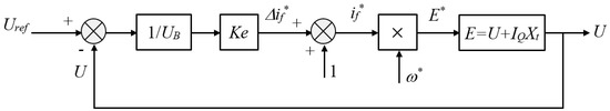
Figure 5.
Control block diagram of the VSG excitation regulator.
In Figure 5, Ke is the slope of reactive power and excitation current characteristics. According to Figure 5 and Equation (9), we have:
E* = [1 + Ke (Uref − Uok)/UB]ω*
The phase voltage of the VSG can be calculated by multiplying UB to both sides of Equation (13):
UB + Ke (Uref − U) = U + IQXt
Thus, the voltage regulation characteristic of the VSG with the excitation regulator can be expressed by solving U from Equation (14) as follows:
where Q = 3UBIQ is the reactive power.
According to Equation (15), it can be found that the VSG has a similar droop characteristic as a SG does, and the droop coefficient is −Xt/(1 + Ke). Consider the reactive power included in Equation (15) and by emulating the voltage regulation characteristic of a synchronous generator, the VSG voltage regulation equation can be designed as follows:
where Qref is the reactive power reference and n is the slope of the voltage regulation characteristic.
U = Uref − n(Q − Qref)
According to Equations (15) and (16), we have [22]:
Thus, the voltage reference satisfying Equation (16) can be calculated with:
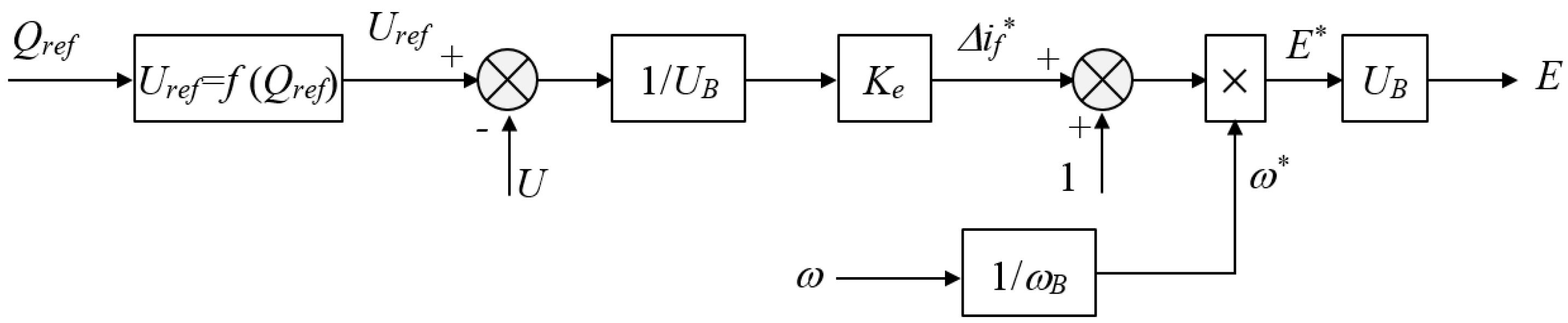
From the above analysis, the control block diagram of the VSG excitation regulator with reactive power control can be illustrated in Figure 6.
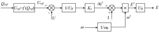
Figure 6.
Control block diagram of the VSG excitation regulator with reactive power control.
2.5. Stability Analysis of the VSG Algorithm
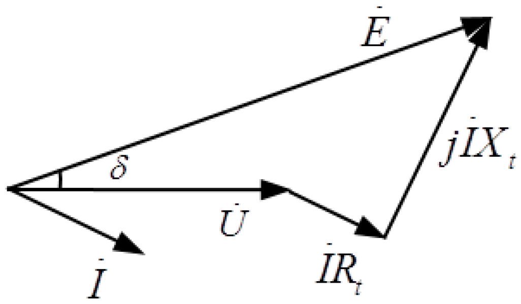
According to the inductive electromotive force Equation (4), the phasor diagram of stator voltage equation is shown in Figure 7, thus the three-phase power can be deduced and shown in the following Equations [23]:
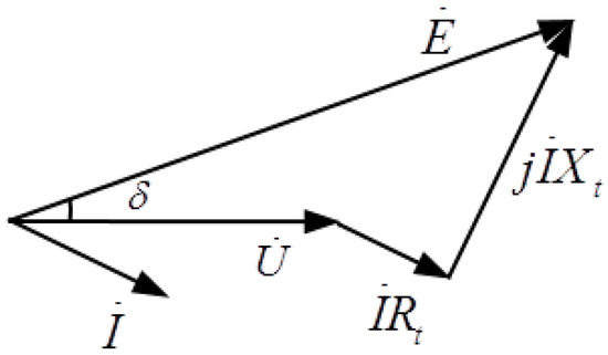
Figure 7.
Voltage vector diagram of VSG.
Active power Equation (20) is analyzed by applying small signal perturbations at the working point of power angle δ. We can have:
where .
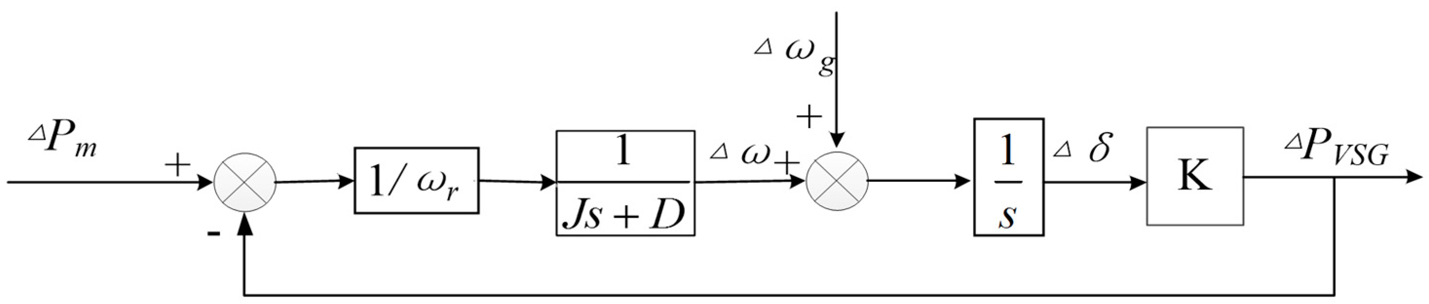
The transfer function block diagram is illustrated in Figure 8, where ωr is the rated angular frequency and ωg is the grid angular frequency.
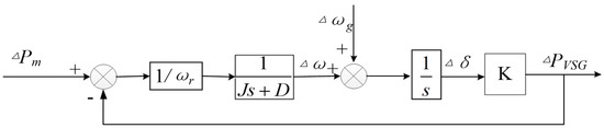
Figure 8.
Active power small signal analysis model.
By simplifying the above figure, the transfer function between the mechanical power input Pm and active power output PVSG, and the transfer function between the stator angular frequency ω and ωs can be deduced as:
According to the transfer functions, the system is a type І system. Therefore, PVSG can track Pm without static errors, and the stator angular frequency ω can also track the grid angular frequency without any static error. The VSG control method has the self-synchronization capability.
With the small signal analysis of VSG, the parameters of the control scheme will affect the system dynamic. For the purpose of parameter sensibility analysis, assume that the rated active power is 10 KW, the stator electromotive force is 240 V, the rated grid frequency is 50 Hz, the phase voltage is 220 V and the stator impedance is (0.3 + j0.3) Ω. When the value of rotational inertia is set to 0.3 Kg·m2 and 0.08 Kg·m2 respectively, the system root locus plots with increasing damping coefficient D are shown in Figure 9.
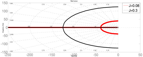
Figure 9.
System root locus plot with increasing damping coefficient D.
From Figure 9, when D is at initial value and equals to 0, the system latent root is on the imaginary axis, thus the system is at the state of critical stability and does not have the ability to resist disturbance. When D increases, the system damping adapts to be increasing, but one of latent roots will get close to the imaginary axis and the stability margin decreases accordingly. On the other hand, the system dynamic response slows down when D keeps increasing.
The performance of the VSG control scheme is also affected by the stator impedance. According to Equations (22) and (23), to keep the VSG system stable, K should be greater than 0. From Equation (21), the expression of K can be transformed to:
where β = arctan (Rt/Xt).
Because K > 0, the system is stable only in case 0 < δ < π/2−β. According to Equation (20), the output power determines the power angle δ. Consequently, the design of the system capacity should consider the power limitation which is dependent on the stator impedance ratio X/R.
Consider the case where the VSG is connected with an infinite power grid and the grid frequency is increased 1 Hz suddenly. The step excitation response of the stator electromotive force angular frequency can be expressed as:
where and .
In order to avoid the sustaining power oscillation when multiple VSG are running in parallel, the damping ratio, denoted as ξ, should be no less than 0.3. In this paper, assume ξ = 0.5 and C(s) can be expressed in Equation (26) by applying the inverse Laplace transform of Equation (25):
According to Equation (26), the angular frequency fluctuation of the stator electromotive force is attenuated with a sinusoid function. The maximum offset value of the power angle appears at the moment when the phase angle of sinusoidal signal is π, and at this time, tmax = 2.54/ωn. The maximum power angle offset value during the fluctuation process can be evaluated by the integral of the second item of Equation (26) with the range of [0, 2.54/ωn], which is:
According to the above analysis, it can be seen that the maximum power angle offset δmax and its appearing time tmax both depend on the rotational inertia J. Consider that δmax and tmax can directly determine the system capability of maintaining the power balance during a transient fluctuation process, the value of rotational inertia J has prominent effects on the system dynamic performance.
3. Hierarchical Control Scheme of Distributed Generation Systems
The secondary voltage and frequency control is widely used in the traditional power systems to decrease the static error and increase the system stability [24]. In a microgrid, because the load can fluctuate in a random way and may be difficult to forecast, sometimes it is not easy to maintain the system voltage and frequency stable without control errors, and distribute the power among generators in an optimized way with only independent control of each converter. Consider that the VSG-based inverter control method makes the inverter possess some dynamic behavior of a SG, this paper adopts the idea of the traditional power system control and designs a hierarchical control scheme for parallel inverters to decrease the static error of the frequency and voltage, and distribute the active and reactive power demand among all the parallel DGs in an equitable way.
3.1. Hierarchical Control Structure Design
The proposed hierarchical control structure, which contains three layers, is shown in Figure 10.
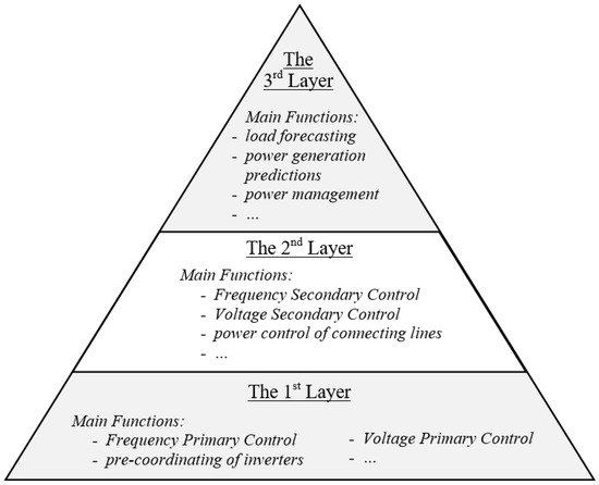
Figure 10.
Hierarchical control structure of parallel DGs.
In the structure shown in Figure 10, each layer exchanges real-time information through communication lines. The rate of the communication between the first and second layers is faster than that between the second and third layers. The function of each layer is as follows:
- The first layer is in the lowest position of the control architecture, and mainly realizes the real-time control of inverters, such as the primary frequency and voltage control in both islanding and grid-connected modes, pre-coordinating of inverters, and etc. To be the bottom layer, its response speed is the fastest and adjusting time is shortest among the three layers.
- The second layer is the coordination layer which focuses on the control of the parallel inverters in a microgrid, and its response speed is slower and adjusting time is longer than those of the lower layer. This layer executes functions including the power control of connecting lines, secondary frequency and voltage regulations in the island mode, per-coordinating of the microgrid, islanding detection, etc.
- The third layer is in the top of the control architecture, and is mainly dedicated to energy management and economic power scheduling. Its response speed is the slowest and adjusting time is the longest among the three layers. According to the energy output forecasting, energy consumption of load, energy exchange plan and operation modes, the active and reactive power outputs of scheduling power generation units are calculated.
The hierarchical control structure shown in Figure 10 is very flexible to integrate different functions. But consider the focus of this paper, in the following sections, only the frequency and voltage hierarchical control are mainly investigated.
The DGs in a distributed generation system can be divided into schedulable and non- schedulable power generators according to the possibilities of scheduling power. In reality, it is not necessary to let all the schedulable power generators to be involved in the secondary voltage and frequency regulations, and in consequence the communication requirements can be reduced and the utilization ratio of the DGs can be improved. In this case, according to whether participating in the secondary voltage and frequency regulations carried out by the second layer, the schedulable power generators in the first layer can be further divided into two categories: the Non-Participating Units (NPUs), which aren’t involved in the secondary frequency and voltage regulations, and will output active and reactive power only according to the references from the second and third layers; and the Participating Units (PUs), which take part in the secondary regulations, and output active and reactive power according to the sum of the scheduled power and the adjustment of the dynamic secondary regulation to remedy the deviation between the output power and the actual load consumption.
3.2. Frequency Hierarchical Control In Island Mode
In a traditional power system, the Frequency Primary Regulation (FPR) can mainly deal with the situation when the load fluctuates with small amplitude and short period (normally less than 10 s), and it can be realized with both PUs and NPUs by primary mover speed regulations to cancel the frequency fluctuations caused by this kind of load changes; while the Frequency Secondary Regulation (FSR) mainly deal with impact load changes with bigger amplitude and longer period (normally from 10 s to 3 min) than the previous situation, and it is executed with the PUs [25,26].
According to the analysis in the Section 2, the block diagram of the VSG based FPR can be shown in Figure 11. When a microgrid operates in the island mode, the reference frequency ωref is the rated frequency ωB; and when the microgrid is in the grid-connected mode, ωref is the grid frequency ωG. The frequency control methods in these two operation modes are similar, but the principles behind the methods are different: in the island mode, the frequency of a microgrid is controlled by all the VSG controllers of parallel inverters and the load power is shared among the DGs; while in connected mode, the frequency is synchronized by the grid, and in this case, the DGs output active and reactive powers according to the references.
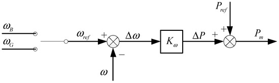
Figure 11.
Block diagram of the VSG-based FPR.
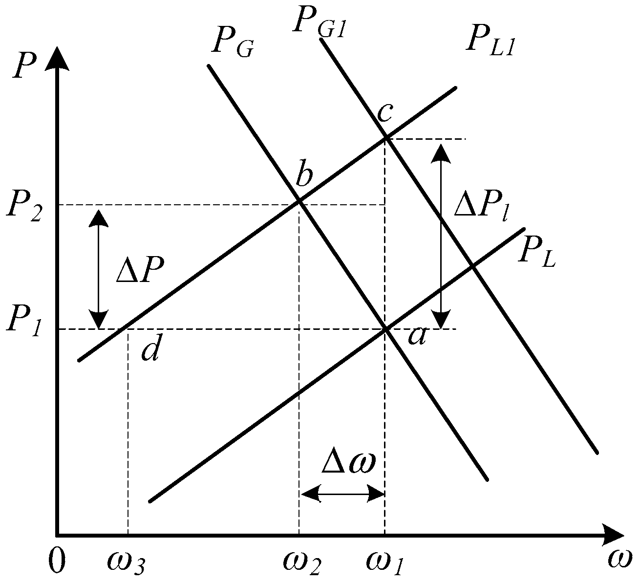
In the island mode, when the load changes slightly, the system frequency fluctuates slightly accordingly and the virtual speed governor reacts quickly because of the proportional controller. In this case, the power output can track the frequency fluctuations in an efficient way, but the static error exists and the frequency will be stabilized close to the rated value eventually. The process of frequency regulation is described in Figure 12.
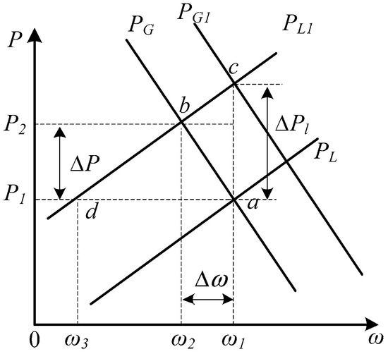
Figure 12.
Regulation process of FPR and FSR.
In Figure 12, suppose that initially the Static Power Frequency Characteristics (SPFC) of load, PL, crosses the equivalent microgrid SPFC, PG, at the rated working point a; at this time, the output active power is P1 and the system frequency is ω1. Suppose that the load active power demand increases ΔPl suddenly and the new SPFC of load accordingly becomes PL1. At this instance, before the frequency regulator can react, the system output active power remains P1 and the frequency decreases. Then, the VSG controller reacts and increases the active power output; and at the same time, the power demand from load decreases because of its self-adjustment effect. After the transition process finishes, the new working point will be point b. At this point, the output active power is P2, which is smaller than the load demand P1 + ΔPl, and the system frequency is ω2, which introduces static error Δω from ω1.
From the above analysis, it can be seen that the VSG-based FPR is a control with steady error, the frequency is not at its rated value, and the output active power is not completely sufficient to the load demand. If the load change is bigger, the errors of frequency and active power will increase and sometimes it is difficult to control and limit the frequency within a permitted range. Consequently, frequency secondary regulation should be applied in the control issues of the parallel DGs with the successful application experience to the traditional power grid. By introducing this idea, the equivalent SPFC of the microgrid can be shifted to PG1, and the new working point will be point c, with which the system frequency remains to be the rated value ω1 and the output active power will be P1 + ΔPl, which can satisfy the increase demand of load power.
To realize FSR, firstly the adjustment value of active power is calculated according to the static error of the frequency; then the adjustment value and the scheduled value are added to obtain a new reference of active power; finally, control the PUs to output the active power with this new reference. This regulation process can be implemented in two ways: distributed control and centralized control [27,28]. In this paper, centralized control method is adopted, with which, the active power adjustment value is calculated by a central unit according to the system frequency deviation, then the power is assigned to each generation unit according to the distribution coefficients.
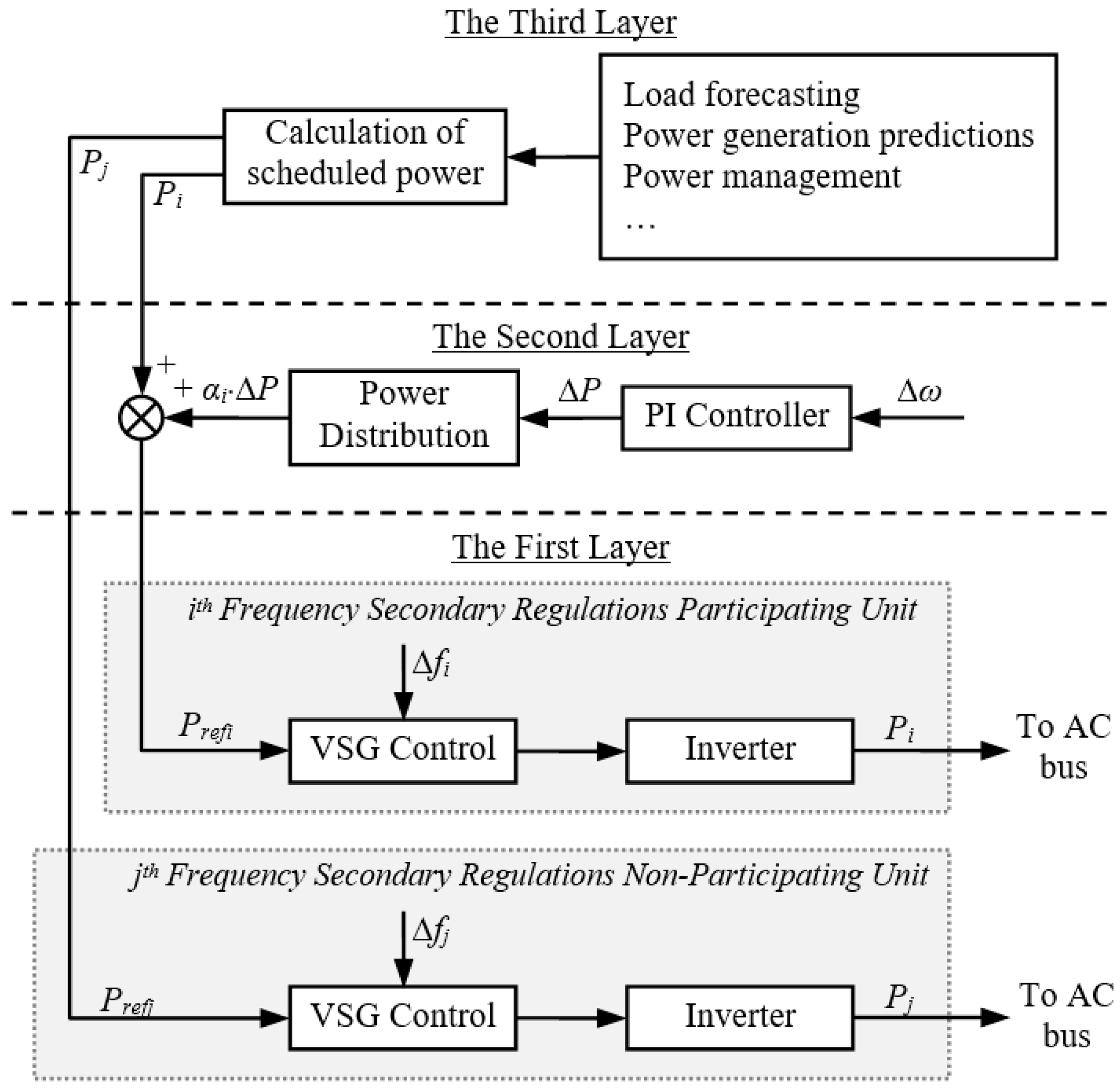
Assuming that in a microgrid there are totally (n + m) DGs, among which the number of PUs and NPUs are n and m respectively; for the ith PU, its power distribution coefficient is αi (i = 1, 2 … n; and α1 + α2 + … + αn = 1), scheduled power output is Pi, and reference value is Prefi including the adjustment value. The structure of the centralized FSR control is shown in Figure 13. The frequency hierarchical control structure of a microgrid is shown in Figure 14.
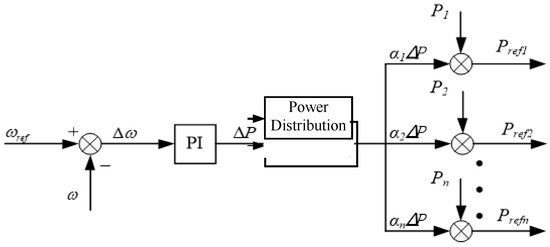
Figure 13.
Structure of the central FSR.
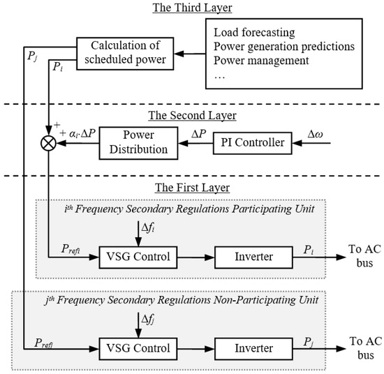
Figure 14.
Frequency hierarchical control structure of a distributed generation system.
From Figure 14, it can be seen that the third layer calculates the scheduled power Pi (i = 1, 2, …, n), Pj (j = 1, 2, …, m) and the power distribution coefficient αi for the coming sampling period with considerations of different factors, such as load forecasting, power generation predictions, the power management strategies of the microgrid, etc. The calculation results are transmitted to all the DGs. In the middle layer, the FSR firstly measures the real time frequency ω of the microgrid and compares it with the rated value ωref. With this error, the total dynamic active power adjustment value ΔP is calculated. Then, with the power distribution coefficient αi, the active power adjustment for the ith PU is calculated with αi·∆P; finally, the scheduled power Pi is added with this adjustment value, and the active power reference is obtained for the ith PU. For a NPU, the reference is the only scheduled value Pj.
3.3. Voltage Hierarchical Control In Island Mode
When a microgrid is working in islanded mode, the change of load reactive power demand will lead to voltage fluctuations. The VSG virtual excitation regulation adopts a P controller and consequently can respond the change quickly and tune the excitation electromotive force to keep the voltage steady. This is the Voltage Primary Regulation (VPR) of VSG-based control. According to the design process in Section 2, the block diagram of VPR can be shown in Figure 15.
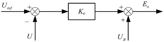
Figure 15.
Block diagram of the VSG based VPR.
In the conventional power system, because of the complexity of network structure, it is difficult to maintain the voltage of all the nodes to be the rated value. In this case, usually keeping the voltage of terminal bus to be rated is more practicable and this normally can guarantee the power quality of most loads [29]. According to this principle of power system voltage control, the idea of controlling the terminal bus voltage is adopted for a microgrid in this paper.
Similar to the FPR process, the VPR can stabilize the voltage at a stable value with static error, and the output reactive power has derivations from the load demand. If a large load change occurs, the voltage error can go outside of the allowed range. Consequently, the Voltage Secondary Regulation (VSR) is necessary to control the system voltage and distribute the reactive power among the parallel DGs.
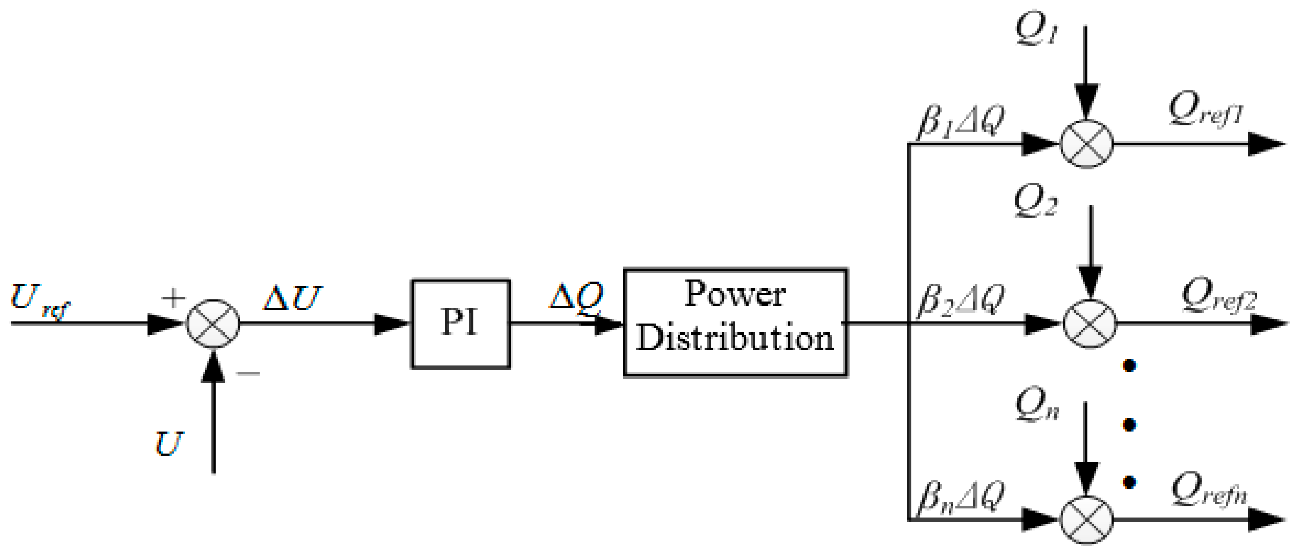
When the reactive power fluctuates in a microgrid, the voltage of terminal bus will fluctuate as a result. Similar to the design process of FSR, the VSR also adopts centralized control method as shown in Figure 16.
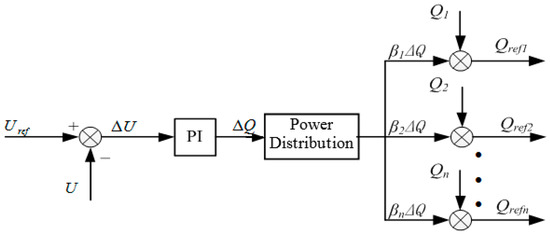
Figure 16.
Structure of central VSR.
In Figure 16, the voltage deviation ΔU is calculated by comparing the measured bus voltage U with the rated value Uref. After a PI controller, the reactive power adjustment value is obtained. According to the reactive power distribution coefficient βi, each VSR PU is assigned with an additional reactive power adjustment βi·∆Q. The voltage hierarchical control structure of a microgrid in island mode is shown in Figure 17.
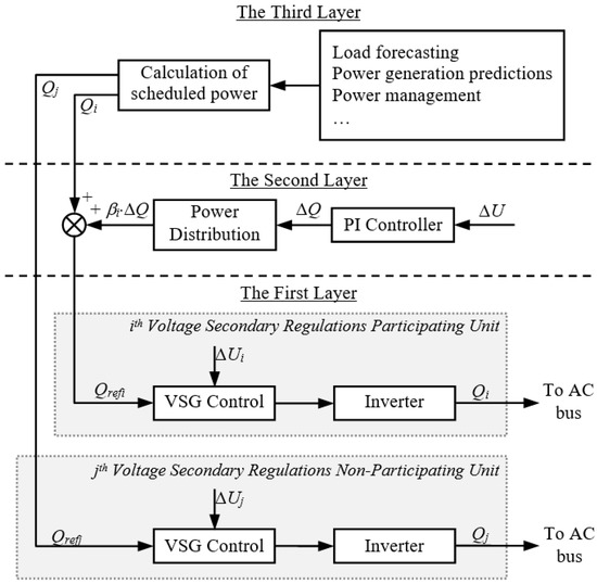
Figure 17.
Voltage hierarchical control structure.
The difference between the VSR PUs and NPUs is the reference value of the reactive power: a PU is given a reference value which is the sum of the scheduled reactive power and VSR adjustment; while the reference of a NPU is only the scheduling reactive power. When the methods of setting these two references are swapped, the roles of PUs and NPUs can be easily changed. Combined the VSR with VPR, the voltage can be well regulated with this hierarchical control.
4. Simulations and Results Analysis
4.1. Comparision between VSG Control and Classical Decoupling Control
To validate the proposed VSG control scheme, some numerical simulations are carried out by using MATLAB/Simulink. The simulation results of two control strategies, the VSG control and classical decoupling control, to an inverter are compared.
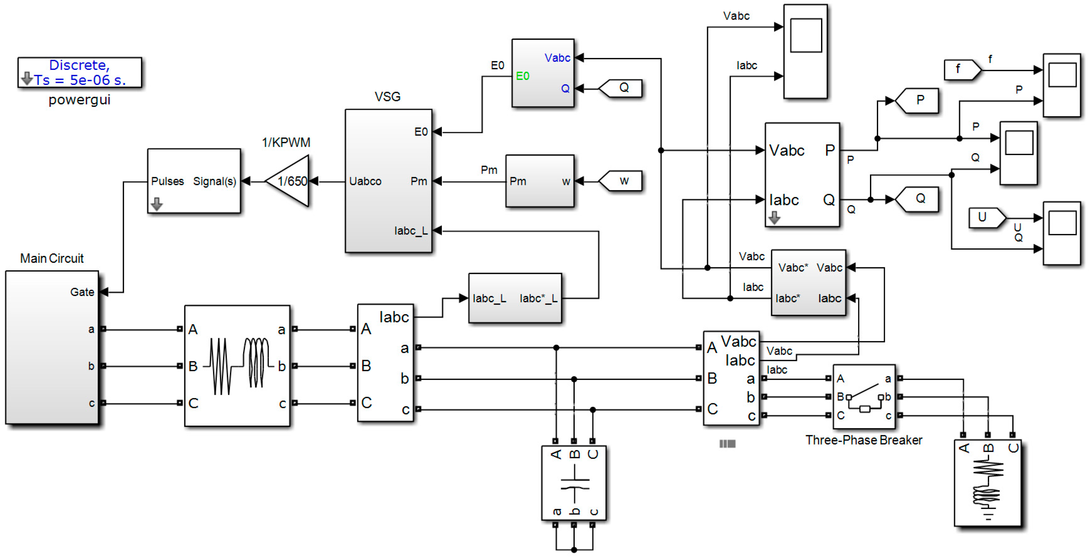
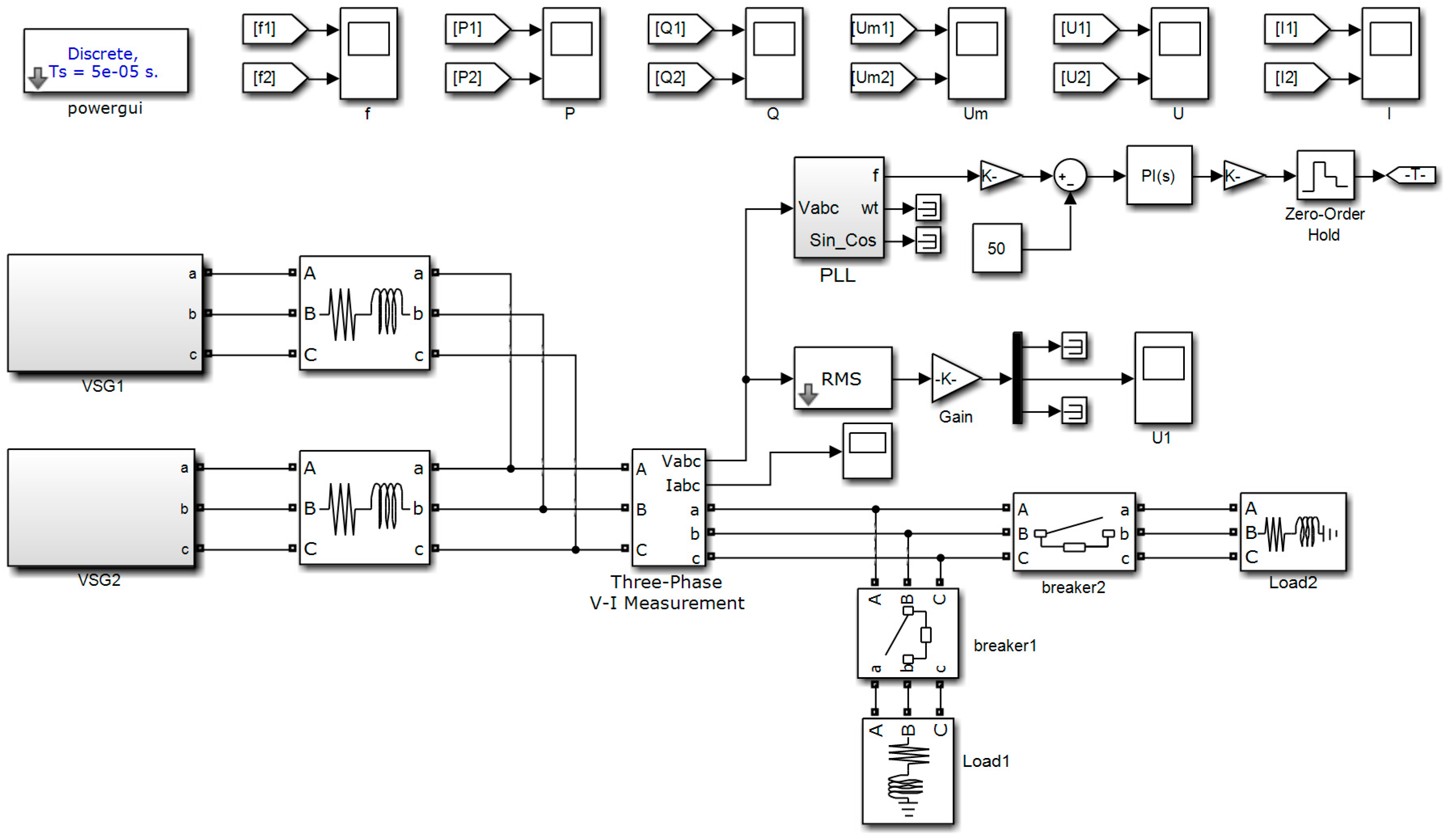
The simulation structure is illustrated in Figure 18 and its VSG control scheme of an inverter is shown in Figure 1. The values of important simulation parameters are summarized in Table 1.
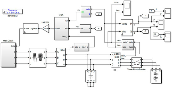
Figure 18.
Simulation structure of a distributed generation system.

Table 1.
Important Simulation Parameters and Values.
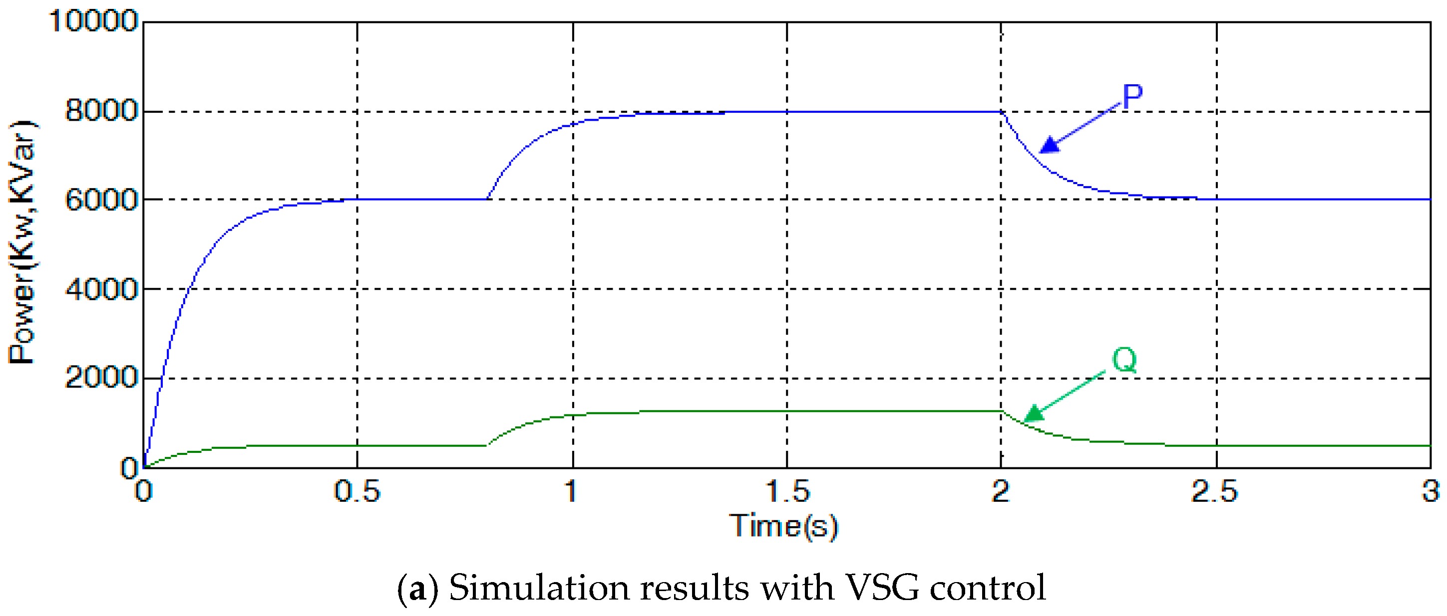
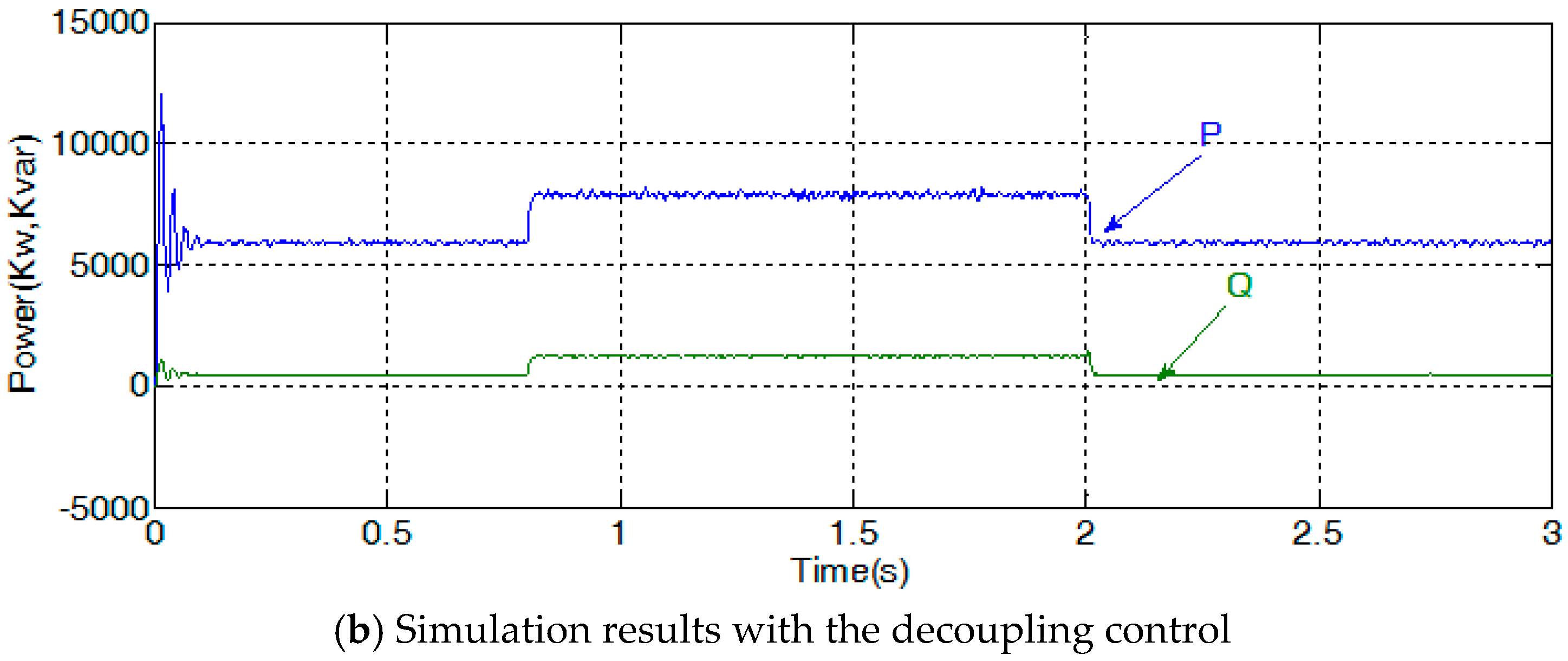
During the simulation process, before 0.8 s, the reference values of active and reactive power are 6000 KW and 500 Kvar respectively. At the instance of 0.8 s, the load active power is increased to 8000 KW, and the reactive power is increased to 800 Kvar. At the moment of 2 s, the power demands of load come back to their initial values. The simulations of VSG control and classical decoupling control are both carried out with this same load power commutation process, and the simulation results are shown in Figure 19 and Figure 20.
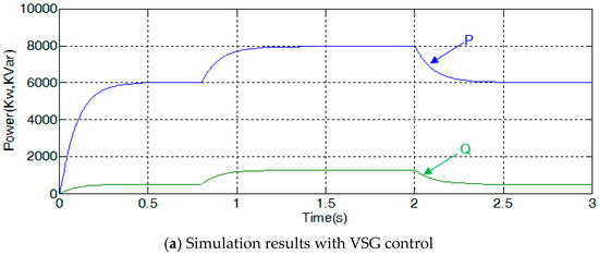
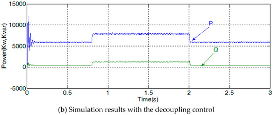
Figure 19.
Comparison of active and reactive power control simulation results.

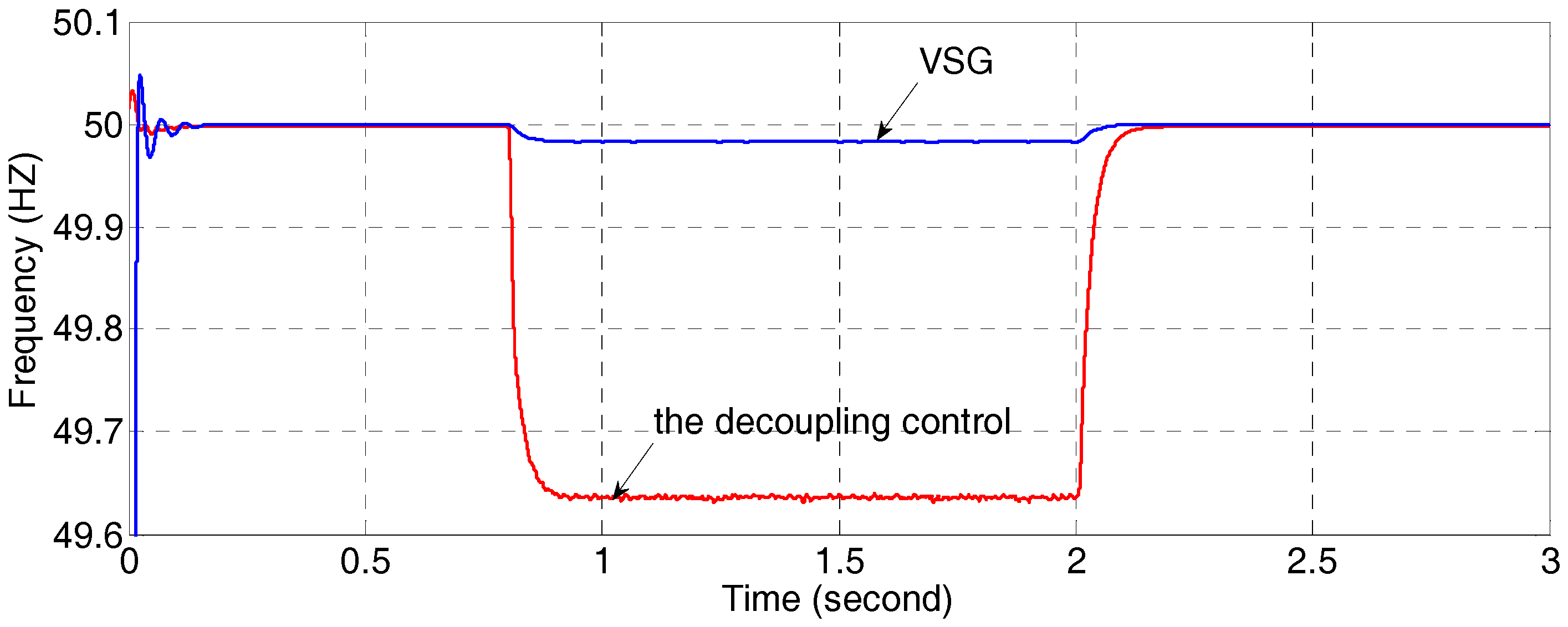
Figure 20.
Frequency control simulation results comparison.
From the results in Figure 19, when the load changes suddenly at 0.8 s and 2 s, the active and reactive powers change more slowly with VSG control than ones with decoupling control. The reason is that with the virtual inertia, although there are no real energy storages included in the system, virtual kinetic energy can be thought existent and is released to or absorbed from the system. Consequently, the power plots with VSG control have less fluctuations than the control effect of decoupling control. The stored virtual kinetic energy W can be calculated by Equation (28), where ωm is the rotor speed.
Comparing the frequency control results shown in Figure 20, it can be found that the frequency regulation performance of VSG is better than the decoupling control. When the load changes, the VSG control method keeps the frequency within the range of 50 ± 0.1 Hz, while the frequency variation amplitude of the decoupling control is greater than 0.4 Hz. Considering the analysis results in the previous sections, when the load power changes, the amplitude of frequency variation depends on the damping coefficient D. According to Equation (4), the relation between power variation and frequency variation can be expressed as:
When ΔP varies in accordance with the load power demands, the angular frequency ω changes accordingly. The damping coefficient D can reduce the fluctuations of ω if D has a big value. But the excessively big value of D will result in longer response time. Therefore, the value of D should be appropriately tuned to satisfy both requirements of inhibiting frequency fluctuation and stabilizing the system.
4.2. Simulations for Parameters Analysis of a VSG Controller
According to the discussions in the previous sections, the values of rotational inertia J and damping coefficient D have important influences on the system dynamics. To verify the analytical results, some simulations for parameters analysis of a VSG controller are carried out by setting different values to these two critical parameters and comparing the output frequency.
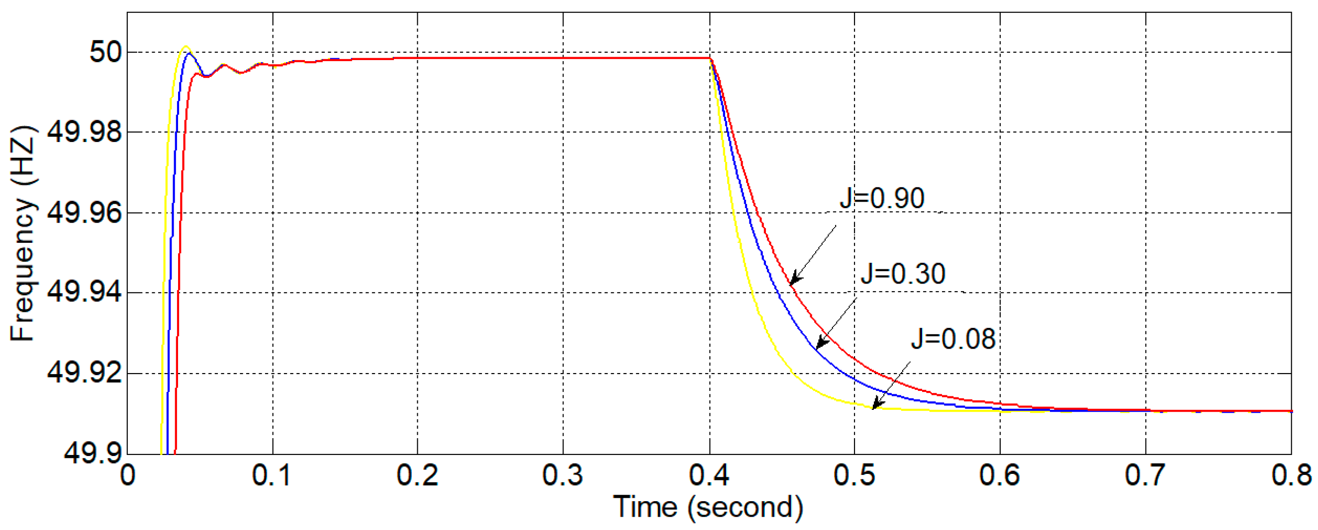
Firstly, assume that the damping coefficient D = 0 and the load is pure resistive; the virtual rotational inertia J is set to be 0.08, 0.30 and 0.90 (in Kg·m2) respectively; the load power is 20 KW. At the moment of 0.4 s, the load power changes to 10 KW, and the simulation results are shown in Figure 21.
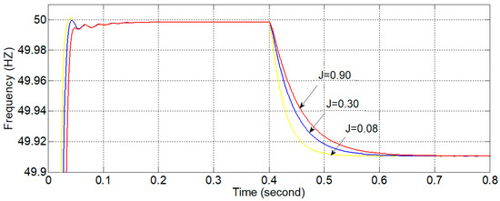
Figure 21.
Frequency plots in rotational inertia J sensibility simulations.
According to the previous analysis, when the power variation ΔP is a constant, the rotational inertia J is inversely proportional to dΔω/dt. Therefore, the value of J does not affect the value of frequency in steady state. But during the transition process, bigger rotational inertia J will slow down the dynamic process. The simulation results in Figure 21 confirm this analytic result.
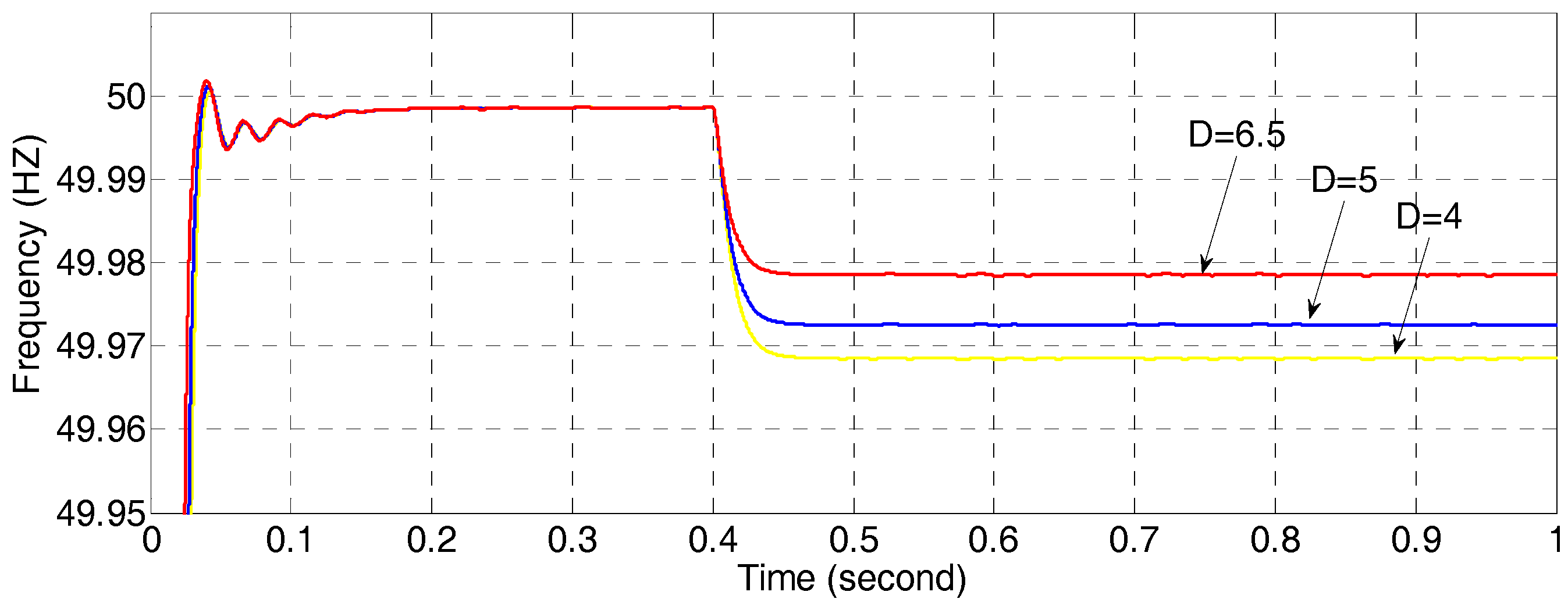
Secondly, the influence of damping coefficient D on the frequency output is verified by a simulation. Let J = 0.33 Kg·m2 and set the value of D to be 4.0, 5.0 and 6.5 respectively. The remaining assumptions are the same as those in the previous simulation, and the simulation results are shown in Figure 22.
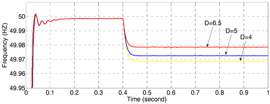
Figure 22.
Frequency plots in damping coefficients D sensibility simulations.
According to the previous analysis, the damping coefficient is inversely proportional to the frequency variation Δω and is independent from dΔω/dt. Therefore, the damping coefficient only effects the frequency in steady state instead of the dynamic process. The simulation results in Figure 22 confirm this analytic result and show that greater damping coefficient can reduce the static error of frequency.
4.3. Simulations of the Frequency Hierarchical Control
To verify the effectiveness of the proposed frequency hierarchical control strategy, a simulation model is set up and shown in Figure 23. In this figure, two VSG controlled parallel DGs are included, and among which, VSG1 is involved in both FPR and FSR, while VSG2 is only involved in the FPR. The main simulation parameters and their values are summarized in the Table 2.
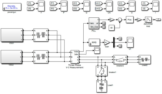
Figure 23.
Frequency hierarchical control strategy simulation blocks.
Table 2.
Simulation Parameters of Frequency Hierarchical Control.
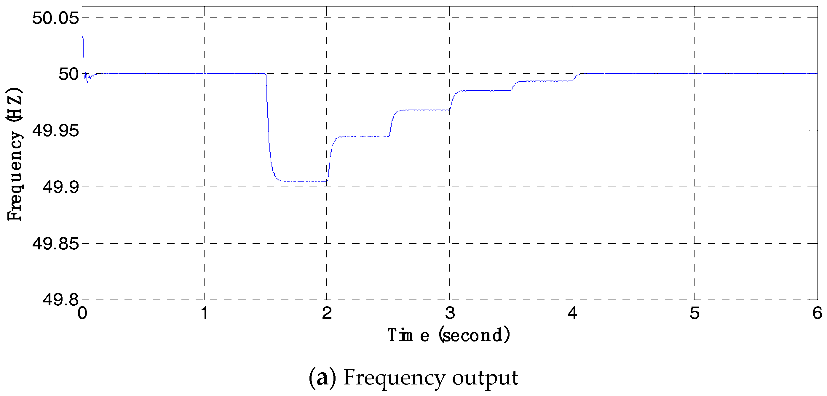
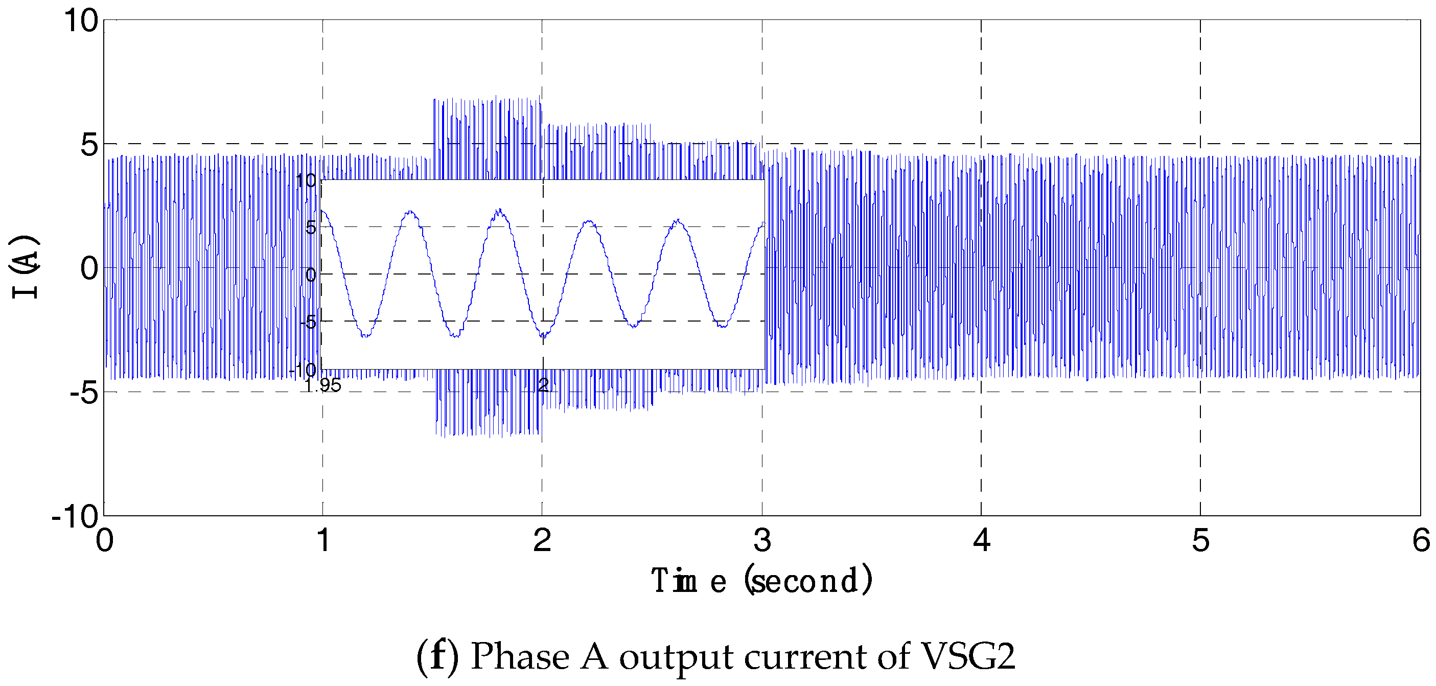
In the beginning of the simulation process, only Load1 is connected to the parallel DGs; at 1.5 s, Load2 is switched on. After the connection of Load2, the power adjustment value is calculated and transmitted to VSG1 (who anticipates FSR) on every 0.5 s. The simulation results are shown in Figure 24.
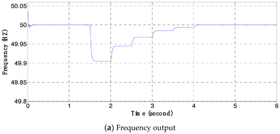
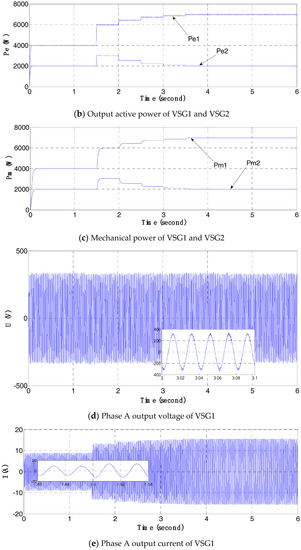
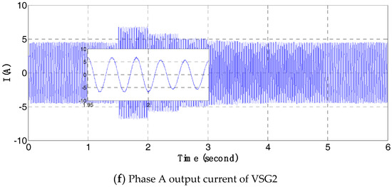
Figure 24.
Simulation result of frequency hierarchical control.
From the simulation results shown in Figure 24, it can be seen that after the connection of Load2, system frequency drops immediately; then VSG1 and VSG2 start to carry out FPR, and the active power output of VSG1 and VSG2 increases. But the output active power of VSG1 and VSG2 still cannot completely meet the active power demand of load because of the limitations of FPR, which bring deviation to the controlled variable. Then the FSR of VSG1 starts to take effect. The active power adjustment value is calculated and sent to VSG1 on every 0.5 s, VSG1 increases its output of active power, and the frequency of the system increases consequently. The increasing of frequency causes the frequency deviation of VSG2 to decrease, and its active power output is also reduced. In the process of FPR and FSR, the output voltage amplitude keeps unchanged and the current changes in accordance with the active power. When the system frequency recovers to the rated value, the active power output of VSG2 also recovers to the reference value.
During the above regulation process, when the active power of loads fluctuates, the FPR and FSR take effect together to control the output active power to meet the demand of the loads, and the frequency is kept stable at its rated value without static error.
4.4. Simulations of the Voltage Hierarchical Control
Some simulations also have been done to verify the control effect of the voltage hierarchical control scheme. The simulation system includes two VSG controlled parallel DGs and both of them are involved in the VSR. The simulation diagram is the same one shown in Figure 23 and the simulation parameters are summarized in Table 3.
Table 3.
Simulation Parameters of Voltage Hierarchical Control.
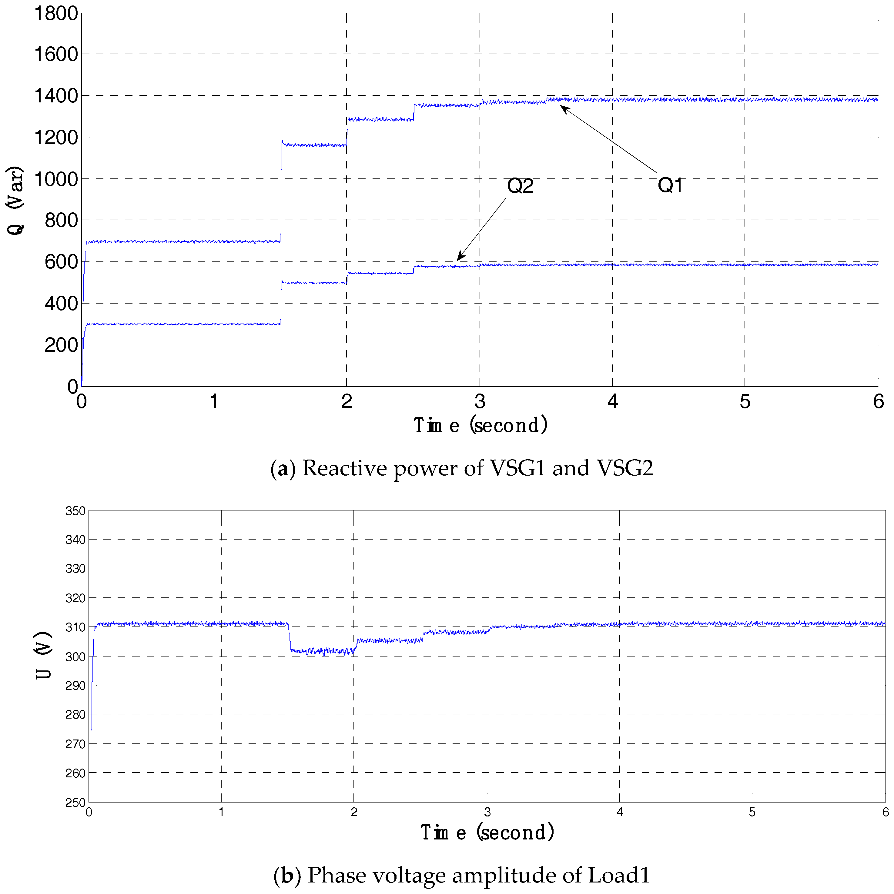
The simulation process is similar with the previous one. At beginning, only Load1 is connected and at 1.5 s, Load2 is connencted to the parallel system. The reactive power distribution coefficient of VSG1 and VSG2 is 0.7 and 0.3 respectively. The reactive power adjustments values are calculated and transmitted to VSG1 and VSG2 in accordance with the distribution proportion of these coefficients. The simulation results are shown in Figure 25.
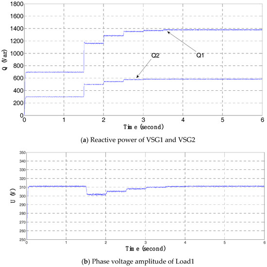
Figure 25.
Simulation result of frequency hierarchical control.
From Figure 25, it can be seen that at 1.5 s, the reactive power demand of the loads increases, accordingly the reactive power outputs of VSG1 and VSG2 increase with big amplitutes because of the VPR; then the VSR starts to take effect, the reactive power outputs of VSG1 and VSG2 increase progressively; accordingly the bus voltage magnitude starts to restore to its rated value and the reactive power demand from load is met. From this regulation process, it can be verified that the VSR can control the voltage at its rated value without error and distribute the load reactive power between parallel DGs.
5. Discussion and Conclusions
In this paper, a VSG-based hierarchical control scheme of parallel DGs is presented. The VSG-based inverter control can deal with the control difficulties caused by the power electronic interfaces, and hierarchical control scheme is designed to increase the control accuracy of the voltage and frequency of a VSG based control system.
The VSG-based control method is firstly deduced from the rotator swing equation and stator electrical equation of a synchronous machine. The design of virtual governor and virtual excitation regulator is introduced in details and the system stability analysis is carried out. Further, the impacts of the two important parameters to the control performance is analyzed, which shows that the damping coefficient affects the frequency only in steady state while the rotational inertial only affects the frequency in dynamic process.
Then a VSG-based hierarchical control scheme is designed, which includes three layers and can realize the functions of voltage and frequency secondary regulations. The secondary control principles and process are illustrated in details for both voltage and frequency regulations.
Finally, simulations are carried out with MATLAB/Simulink to verify the effectiveness of the proposed control scheme. The effect of the VSG-based inverter control method is shown by comparing the control results with the decoupling control strategy. The theoretical analysis results of controller parameters are verified by the simulations. Further, three layers’ hierarchical control simulations for both frequency and voltage secondary regulations have been done. The simulation results show the VSG-based hierarchical control of parallel DGs can realize error free control for frequency and voltage, and can control the DGs to share the load proportionally with the capacities of DGs to meet the demand of loads.
From the design and analysis procedure of the VSG-based hierarchical control scheme, and also the simulation results, it can be seen that the core idea of VSG control is to embed the synchronous generator equations including the virtual inertia J and the virtual damping coefficient D into the control loop of the inverters to emulate the external dynamic characteristic of a traditional synchronous generator set. Consequently, the VSG control-based inverter can realize power exchanges between the power source and the grid in patterns similar to the external behavior of the synchronous generator set. By doing in this way, it helps to stabilize the output parameters. And the introduction of secondary voltage and frequency regulations, which are very important concepts in the conventional power grid, can help removing the static errors existing in the VSG control.
Although in this paper, the effeteness of the proposed VSG-based hierarchical control scheme of distributed generation systems is verified only by MATLAB simulations, the feasibility of this method in practical systems still need to be further confirmed. Accordingly, realize this scheme in an experimental platform for verifications is the next research mission of our research team.
Acknowledgments
Projects (with Grant No. 61673260 and 61603246) are supported by National Natural Science Foundation of China; and sponsored by Natural Science Foundation of Shanghai (with Grant No. 16ZR1414300).
Author Contributions
G.Y. and Z.L. designed the system architecture and performed the simulations experiments; M.B. and Y.W. supervised the whole research procedure of this paper; and L.M. analyzed the data and verified the simulation results.
Conflicts of Interest
The authors declare no conflict of interest.
References
- Yao, G.; Lu, Y.; Tang, T.; Benbouzid, M.; Zheng, Y.; Wang, T. A central control strategy of parallel inverters in AC microgrid. In Proceedings of the IECON 2013—39th Annual Conference of the IEEE Industrial Electronics Society, Vienna, Austria, 10–13 November 2013; pp. 7112–7117. [Google Scholar]
- Alipoor, J.; Miura, Y.; Ise, T. Stability Assessment and Optimization Methods for Microgrid with Multiple VSG Units. IEEE Trans. Smart Grid 2016. [Google Scholar] [CrossRef]
- Torres, L.M.A.; Lopes, L.A.C.; Morán, T.L.A.; Espinoza, C.J.R. Self-Tuning Virtual Synchronous Machine: A Control Strategy for Energy Storage Systems to Support Dynamic Frequency Control. IEEE Trans. Energy Convers. 2014, 29, 833–840. [Google Scholar] [CrossRef]
- Zhong, Q.C.; Weiss, G. Static synchronous generators for distributed generation and renewable energy. In Proceedings of the 2009 IEEE/PES Power Systems Conference and Exposition, Seattle, WA, USA, 15–18 March 2009; pp. 1–6. [Google Scholar]
- Wang, S.; Hu, J.; Yuan, X.; Sun, L. On Inertial Dynamics of Virtual-Synchronous-Controlled DFIG-Based Wind Turbines. IEEE Trans. Energy Convers. 2015, 30, 1691–1702. [Google Scholar] [CrossRef]
- Karapanos, V.; de Haan, S.; Zwetsloot, K. Real time simulation of a power system with VSG hardware in the loop. In Proceedings of the IECON 2011—37th Annual Conference of the IEEE Industrial Electronics Society, Melbourne, Australia, 7–10 November 2011; pp. 3748–3754. [Google Scholar]
- Zhong, Q.C.; Weiss, G. Synchronverters: Inverters That Mimic Synchronous Generators. IEEE Trans. Ind. Electron. 2011, 58, 1259–1267. [Google Scholar] [CrossRef]
- Arani, M.F.M.; El-Saadany, E.F. Implementing Virtual Inertia in DFIG-Based Wind Power Generation. IEEE Trans. Power Syst. 2013, 28, 1373–1384. [Google Scholar] [CrossRef]
- Guan, M.; Pan, W.; Zhang, J.; Hao, Q.; Cheng, J.; Zheng, X. Synchronous Generator Emulation Control Strategy for Voltage Source Converter (VSC) Stations. IEEE Trans. Power Syst. 2015, 30, 3093–3101. [Google Scholar] [CrossRef]
- Paquette, A.D.; Divan, D.M. Virtual Impedance Current Limiting for Inverters in Microgrids with Synchronous Generators. IEEE Trans. Ind. Appl. 2015, 51, 1630–1638. [Google Scholar] [CrossRef]
- Liu, J.; Miura, Y.; Ise, T. Comparison of Dynamic Characteristics between Virtual Synchronous Generator and Droop Control in Inverter-Based Distributed Generators. IEEE Trans. Power Electron. 2016, 31, 3600–3611. [Google Scholar] [CrossRef]
- Wu, H.; Yang, D.; Chen, X.; Zhao, W.; Lv, Z.; Zhong, Q.C. Small-Signal Modeling and Parameters Design for Virtual Synchronous Generators. IEEE Trans. Ind. Electron. 2016, 63, 4292–4303. [Google Scholar] [CrossRef]
- Yao, G.; Lu, Z.; Benbouzid, M.; Tang, T.; Han, J. A virtual synchronous generator based inverter control method for distributed generation systems. In Proceedings of the IECON 2015—41st Annual Conference of the IEEE Industrial Electronics Society, Yokohama, Japan, 9–12 November 2015; pp. 2112–2117. [Google Scholar]
- Dou, C.X.; Liu, B. Multi-Agent Based Hierarchical Hybrid Control for Smart Microgrid. IEEE Trans. Smart Grid 2013, 4, 771–778. [Google Scholar] [CrossRef]
- Mojica-Nava, E.; Macana, C.A.; Quijano, N. Dynamic Population Games for Optimal Dispatch on Hierarchical Microgrid Control. IEEE Trans. Syst. Man Cybern. Syst. 2014, 44, 306–317. [Google Scholar] [CrossRef]
- Han, Y.; Shen, P.; Zhao, X.; Guerrero, J.M. Control Strategies for Islanded Microgrid Using Enhanced Hierarchical Control Structure With Multiple Current-Loop Damping Schemes. IEEE Trans. Smart Grid 2017, 8, 1139–1153. [Google Scholar] [CrossRef]
- Feng, W.; Sun, K.; Guan, Y.; Guerrero, J.; Xiao, X. Active Power Quality Improvement Strategy for Grid-connected Microgrid Based on Hierarchical Control. IEEE Trans. Smart Grid 2017. [Google Scholar] [CrossRef]
- Cintuglu, M.H.; Youssef, T.; Mohammed, O.A. Development and Application of a Real-Time Testbed for Multiagent System Interoperability: A Case Study on Hierarchical Microgrid Control. IEEE Trans. Smart Grid 2016. [Google Scholar] [CrossRef]
- Benbouzid, M.E.H.; Beltran, B.; Amirat, Y.; Yao, G.; Han, J.; Mangel, H. Second-order sliding mode control for DFIG-based wind turbines fault ride-through capability enhancement. ISA Trans. 2014, 53, 827–833. [Google Scholar] [CrossRef] [PubMed]
- Alipoor, J.; Miura, Y.; Ise, T. Power System Stabilization Using Virtual Synchronous Generator with Alternating Moment of Inertia. IEEE J. Emerg. Sel. Top. Power Electron. 2016, 3, 451–458. [Google Scholar] [CrossRef]
- Li, C.; Xu, J.; Zhao, C. A Coherency-Based Equivalence Method for MMC Inverters Using Virtual Synchronous Generator Control. IEEE Trans. Power Deliv. 2016, 31, 1369–1378. [Google Scholar] [CrossRef]
- Lv, Z.; Liang, Y.; Zeng, Z.; Yang, L.; Liu, H.; Yuan, Q. Virtual Synchronous Motor Based Contrl Scheme of Fast Charger for Electric Vehicle Application. Proc. CSEE 2014, 34, 4287–4294. [Google Scholar]
- Meng, J.; Wang, Y.; Shi, X.; Fu, C.; Li, P. Control Strategy and Parameter Analysis of Distributed Inverters Based on VSG. Trans. China Electrotech. Soc. 2014, 29, 1–10. [Google Scholar]
- Lu, L.Y.; Chu, C.C. Consensus-Based Secondary Frequency and Voltage Droop Control of Virtual Synchronous Generators for Isolated AC Micro-Grids. IEEE J. Emerg. Sel. Top. Circuits Syst. 2015, 5, 443–455. [Google Scholar] [CrossRef]
- Sobierajski, M.; Rojewski, W. Primary and secondary frequency control in a small power system (SPS) with rotating and static sources after islanding. In Proceedings of the 2015 Modern Electric Power Systems (MEPS), Wroclaw, Poland, 6–9 July 2015; pp. 1–8. [Google Scholar]
- Yu, Z.; Zhao, D.; Xia, J.; Du, Z. New Algorithm for Dynamic Optimal Reactive Power and Voltage Control. J. Xi’an Jiaotong Univ. 2006, 40, 1441–1445. [Google Scholar]
- Xu, C.; Liu, N.; Zhao, H.; Zhu, G. A novel frequency control strategy of micro-grid based on the secondary frequency regulation of power system. Power Syst. Prot. Control 2013, 41, 14–20. [Google Scholar]
- Frack, P.F.; Mercado, P.E.; Molina, M.G.; Watanabe, E.H.; de Doncker, R.W.; Stagge, H. Control Strategy for Frequency Control in Autonomous Microgrids. IEEE J. Emerg. Sel. Top. Power Electron. 2015, 3, 1046–1055. [Google Scholar] [CrossRef]
- Li, G.; He, G.; Bao, W.; Sun, Y.; Hao, M. A hierarchical control strategy of micro-grid based on grid-friendly distributed generation technology. In Proceedings of the 2014 International Conference on Power System Technology (POWERCON), Chengdu, China, 20–22 October 2014; pp. 3181–3185. [Google Scholar]


© 2017 by the authors. Licensee MDPI, Basel, Switzerland. This article is an open access article distributed under the terms and conditions of the Creative Commons Attribution (CC BY) license (http://creativecommons.org/licenses/by/4.0/).