Article

System Efficiency Improvement for Electric Vehicles Adopting a Permanent Magnet Synchronous Motor Direct Drive System

Department of Electrical Engineering, Harbin Institute of Technology University, Room 205, Building 2C, Science Park of Harbin Institute of Technology, Nangang District, Harbin 150001, China
*
Author to whom correspondence should be addressed.
Energies 2017, 10(12), 2030; https://doi.org/10.3390/en10122030
Submission received: 18 October 2017 / Revised: 17 November 2017 / Accepted: 27 November 2017 / Published: 1 December 2017
(This article belongs to the Section F: Electrical Engineering)

Abstract

:
To improve the endurance mileage of electric vehicles (EVs), it is important to decrease the energy consumption of the Permanent Magnet Synchronous Motor (PMSM) drive system. This paper proposes a novel loss optimization control strategy named system efficiency improvement control which can optimize both inverter and motor losses. A nonlinear power converter loss model is built to fit the nonlinear characteristics of power devices. This paper uses double Fourier integral analysis to analytically calculate the fundamental and harmonic components of motor current by which the fundamental motor loss and harmonic motor loss can be accurately analyzed. From these loss models, a whole-frequency-domain system loss model is derived and presented. Based on the system loss model, the system efficiency improvement control method applies the genetic algorithm to adjust the motor current and PWM frequency together to optimize the inverter and motor losses by which the system efficiency can be significantly improved without seriously influence on the system stability over the whole operation range of EVs. The optimal effects of system efficiency is verified by the experimental results in both Si-IGBT-based PMSM system and SiC-MOSFET-based system.

1. Introduction

One of the major challenges currently faced in the transportation sector is how to decrease the dependency on fossil fuels and thus reduce the emission of greenhouse gases. As electric vehicles (EVs) have the advantage of eliminating the automobile exhaust and offer an ultimate solution for sustainable personal mobility [1,2], EVs seem to be one of the best future alternatives for the automotive industry and transportation [3]. However, the limited operational range of EVs is a major drawback which is mostly affected by the battery management system and motor drive system. As the motor drive system is the main power source of EVs, the efficiency of the drive system will directly influence their mileage endurance. Compared with induction motors (IMs) and switched reluctance motors (SRMs) [4,5], permanent magnet synchronous motors (PMSMs) with their advantage of high power density and high efficiency, can decrease the energy consumption and improve the operational mileage of EVs [6,7,8], therefore, the PMSM direct drive system has been widely applied in EVs for transportation.
The optimization of the electromagnetic structure and control strategy of PMSMs has been widely discussed in recent years. There are several PMSM control strategies, such as id = 0 control, maximum torque per ampere (MTPA) control, maximum speed per voltage (MSPV) control, unity power factor (UPF) control, loss model control (LMC) and etc. [9,10,11,12,13,14,15,16,17,18,19,20,21,22,23,24]. The id = 0 control is the most conventional vector control method used in PMSM drive systems. In [9,10,11], the finite element method (FEM) is used to calculate the motor loss, and the id = 0 control is used to drive the PMSM system to verify the performance of a PMSM. By keeping the motor current in the d-axis at zero, the id = 0 control can make the electromagnetic torque and q-axis motor current proportional, and will not damage the magnetic properties of the permanent magnet. However, in [12], the id = 0 control method could not minimize the stator current in the interior of a PMSM in which the d-axis magnetic inductance is not equal to q-axis magnetic inductance, and could not achieve minimum copper loss in IPMSMs. Compared with other control strategies, the MTPA control method can take advantage of the reluctance torque of the motor, by which the stator current is decreased [13,14,15,16]. In [16], the improved MTPA control takes the core saturation and cross coupling of the d- and q-axis magnetic flux into account, and the motor performance was optimized with the consideration of the impact of various temperatures. The MTPA control can obtain the minimum stator current and achieve the least copper loss below the rated speed. Meanwhile, the MSPV control can optimize the stator voltage and obtain the optimal stator iron below rated torque [17]. However, as the losses of a PMSM are comprised of copper loss and iron loss, both the MTPA control method and MSPV control method only consider part of the total motor loss, and ignore the coupling relationship between copper loss and iron loss. Therefore, neither the MTPA control strategy nor the MSPV control strategy will achieve the maximum motor efficiency in PMSMs [18]. The UPF control can keep the power factor of PMSMs to one and decrease the energy consumption in the power transfer process [19,20,21]. In Ref. [21], a PMSM drive system with small DC-link capacitor applied UPF control to stabilize the motor driving and decrease the energy loss on the input side. As the UPF control does not take into consideration the power loss in PMSMs, the motor efficiency will not always achieve the maximum value under UPF control. The LMC can optimize both copper loss and iron loss by the PMSM loss model and improve the motor efficiency of the PMSM system [22,23,24]. In Ref. [23], the motor iron loss is calculated by the iron loss resistance, and both the iron loss and copper loss are optimized. The LMC enables the drivetrain to operate safely at the maximum attainable performance limits. In Ref. [24], the Bertotti iron loss formula is used to analyze the stator iron loss, and iron loss is verified by the FEM model. Based on the loss model, the proposed control method fully considers the cross effect and iron loss, and can maximize the efficiency of PMSMs. However, these recent optimized motor efficiency control strategies only focus on the optimization of the motor loss, and neglect the coupling relationship between motor loss and inverter loss. Therefore, as the inverter loss is an important part of system loss in the PMSM system for transportation, these motor control strategies will not achieve the maximum system efficiency.
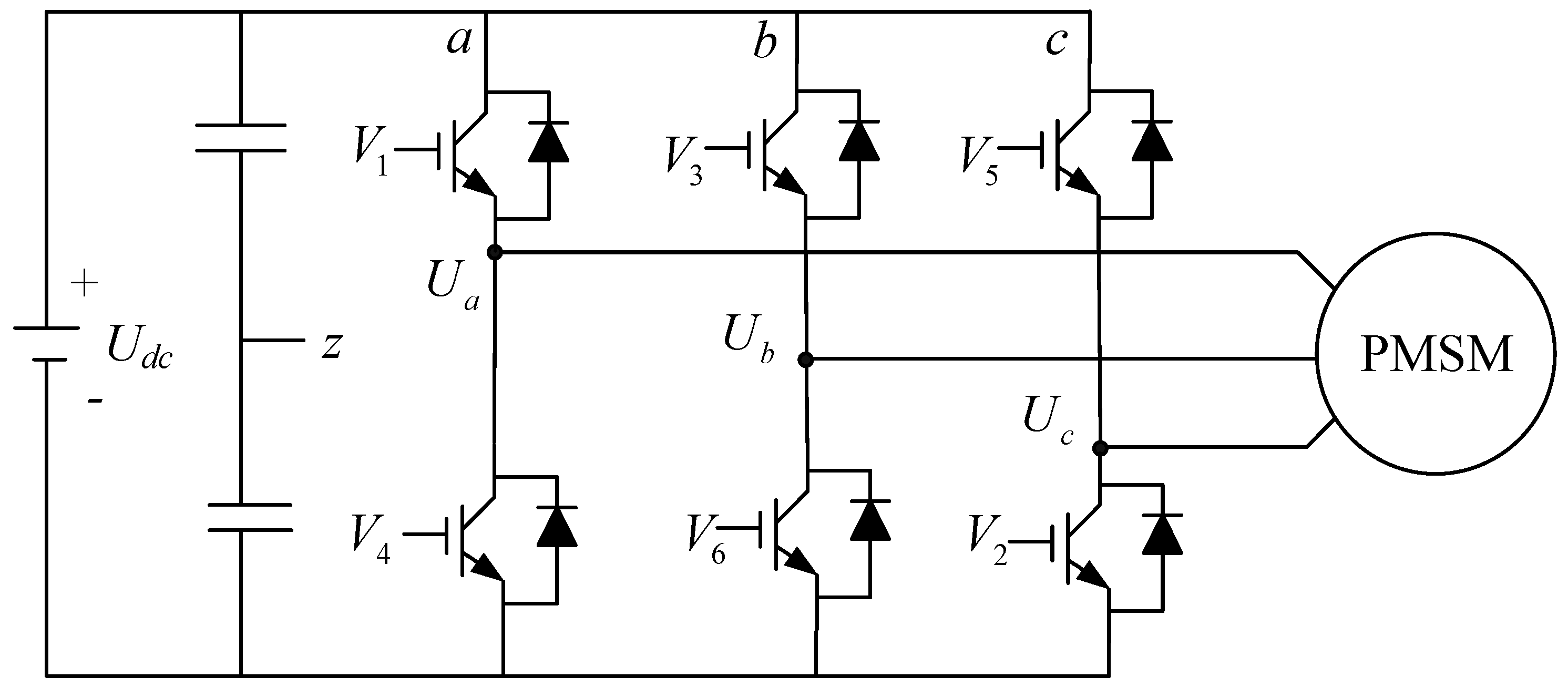
There are also many control strategies for three-phase half-bridge inverters in the PMSM drive system [25]. Modern methods about three-phase inverters such as selected harmonic elimination pulse width modulation (SHEPWM) [26], current harmonic distortion minimization PWM (CHMPWM) [27], harmonic injection PWM (HIPWM) [28], space vector pulse width modulation (SVPWM) [29], etc., always focus on the modulation optimization to decrease the harmonic components of the output voltage in the three-phase inverter. In Ref. [26], a method of smooth transition between different SHEPWMs is proposed to adapt to the SPMSMs and IPMSMs, by which smooth transition of current is guaranteed and the harmonic current is reduced. In Ref. [27], considering the saliency ratio and load angle constraints, a new current harmonic evaluation index is proposed, and based on it, the improved CHMPWM guarantees good performance of both current THD and the specific order current harmonics. All these control strategies ignore the coupling relationship between motor loss and inverter loss. As the inverter loss is an important part of the efficient performance in the PMSM drive system, the efficiency optimization of the three-phase inverter will directly improve the power loss of a PMSM system. Therefore, to acquire a higher system efficiency of a PMSM drive system, The PWM control strategy must take consideration both harmonic components of output voltage and the power loss of power devices in the three-phase bridge inverter.
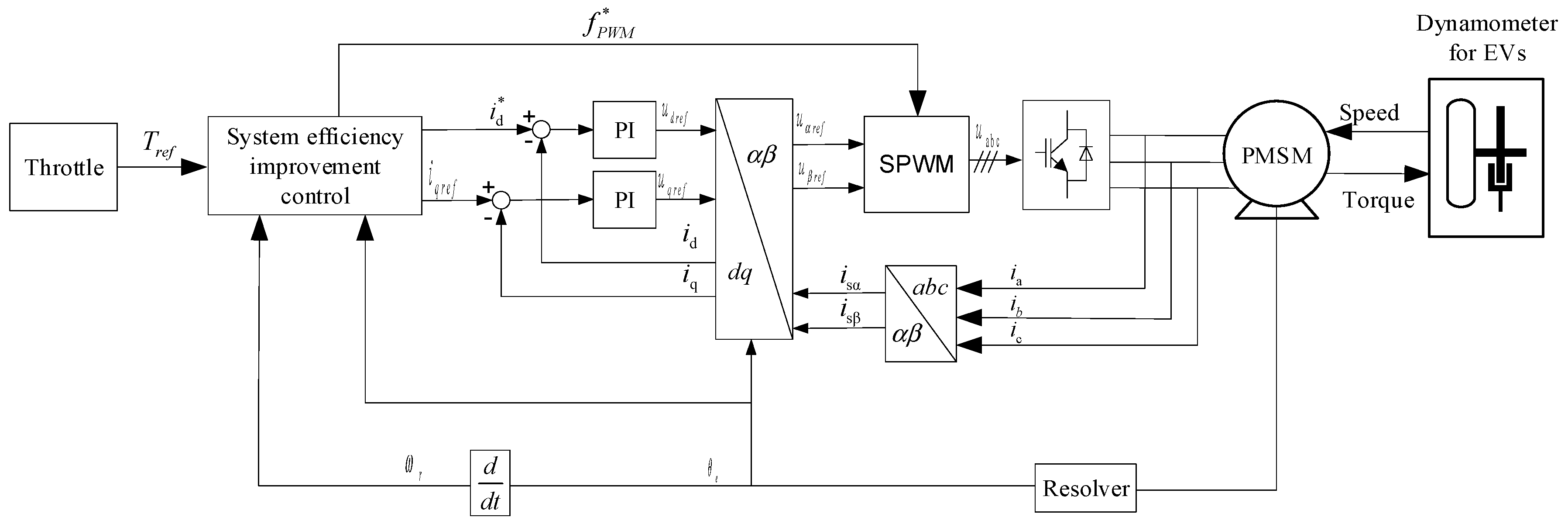
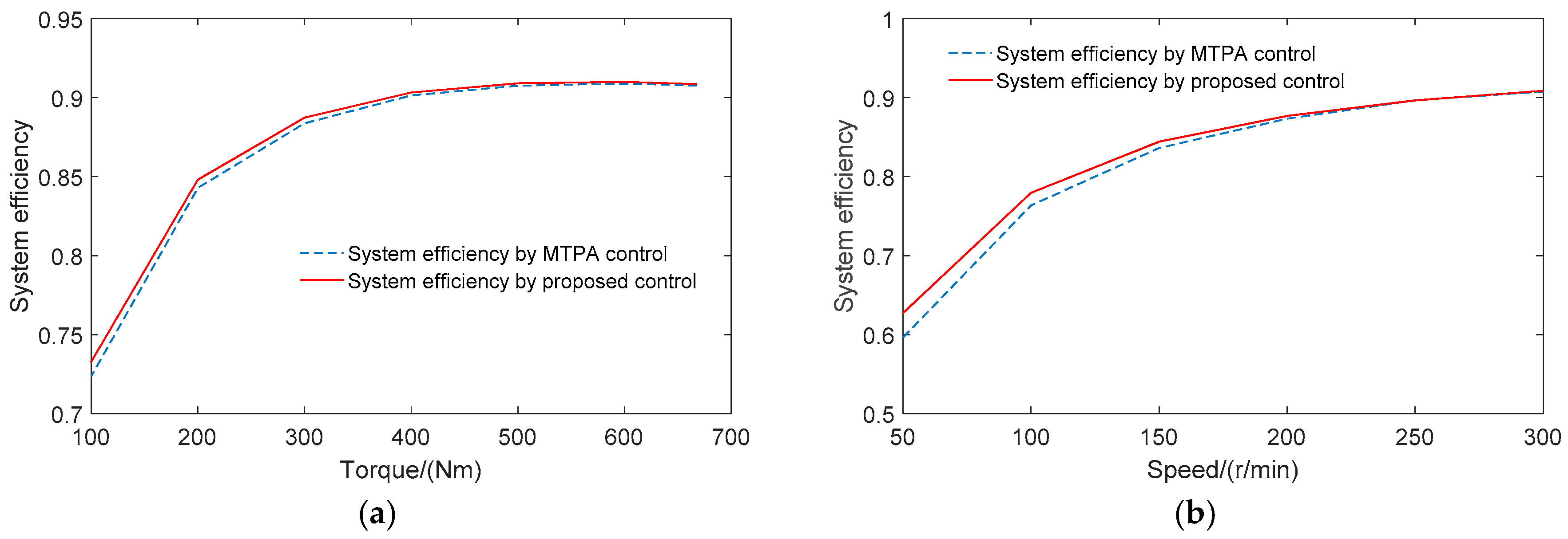
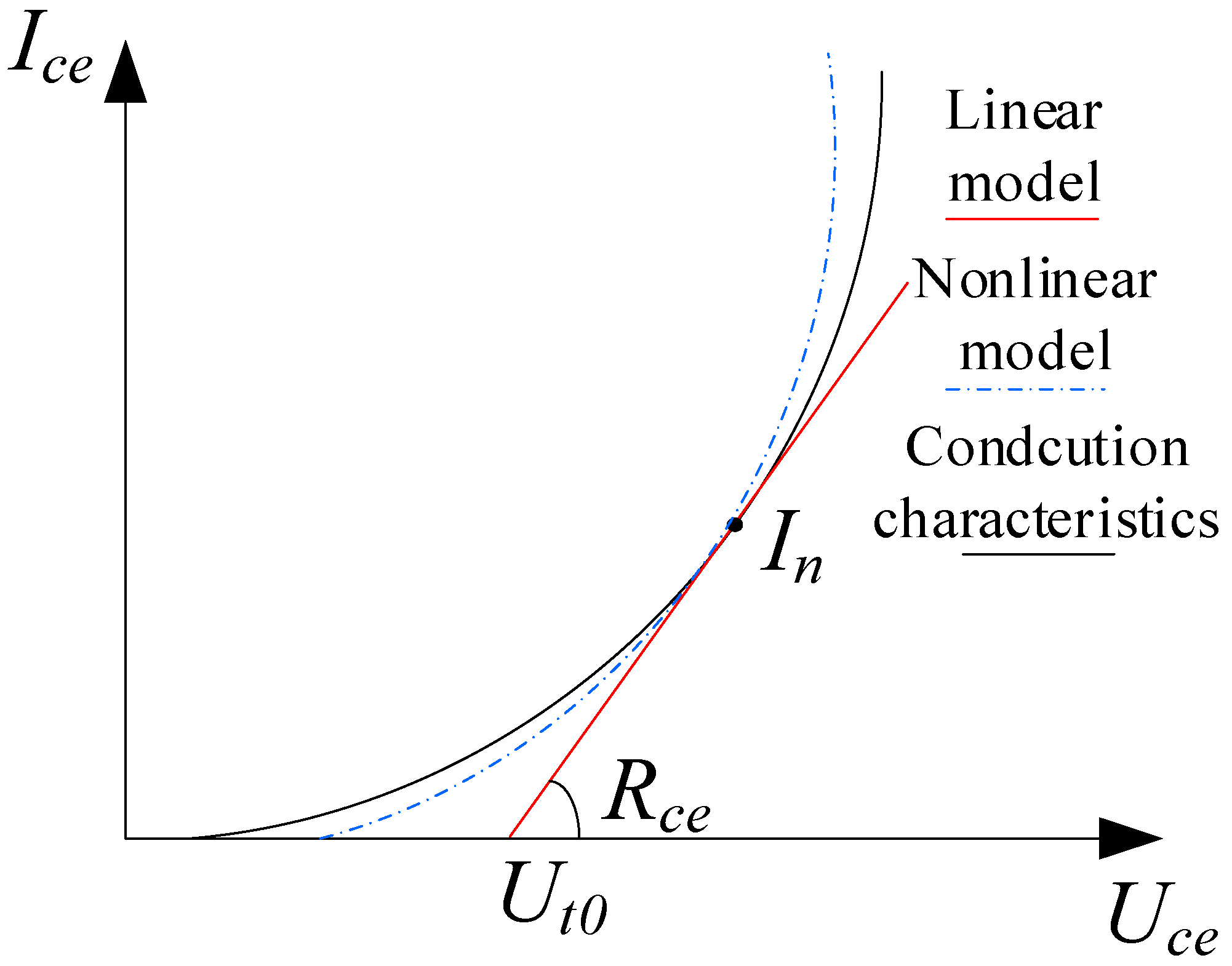
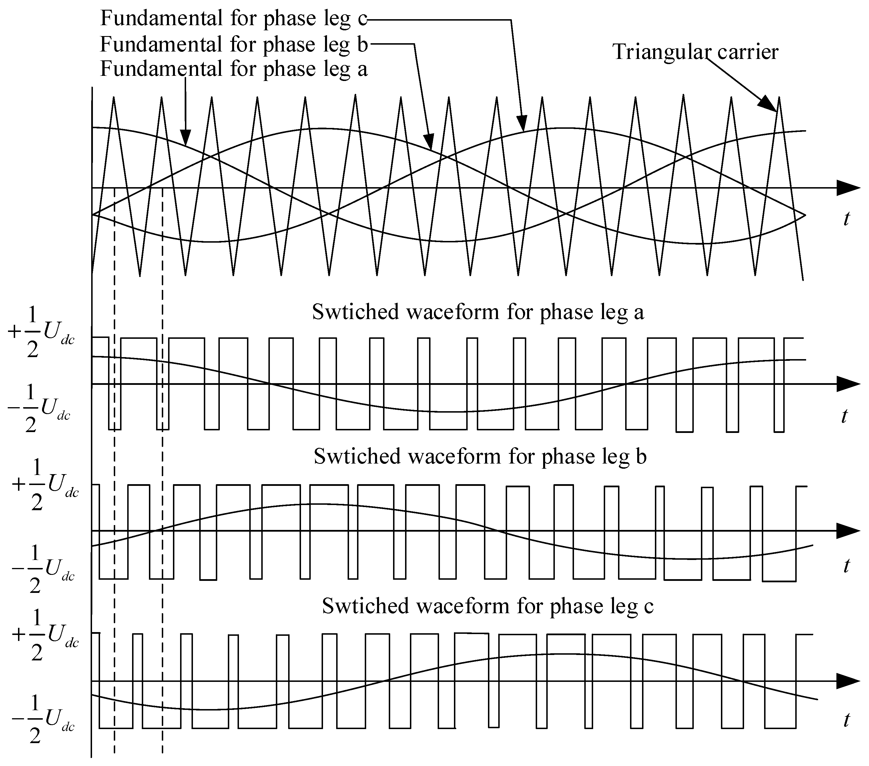
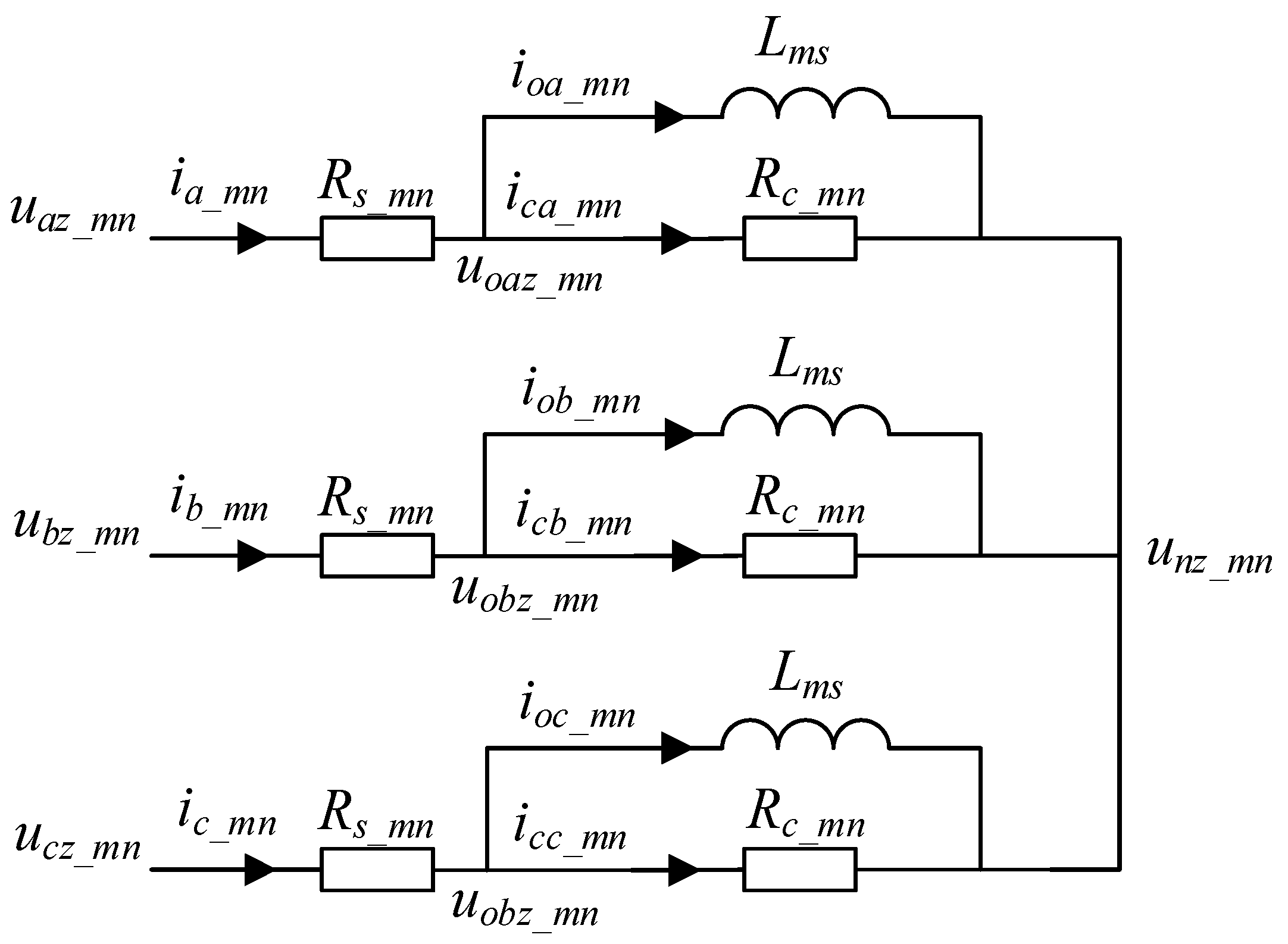
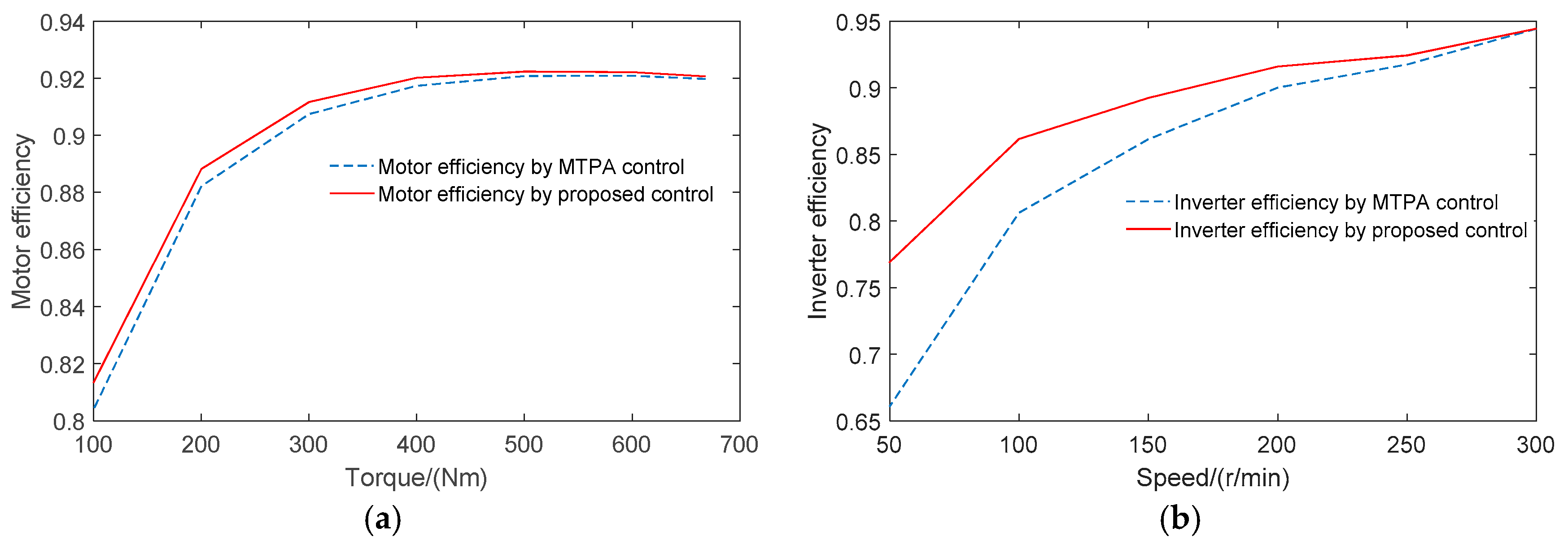
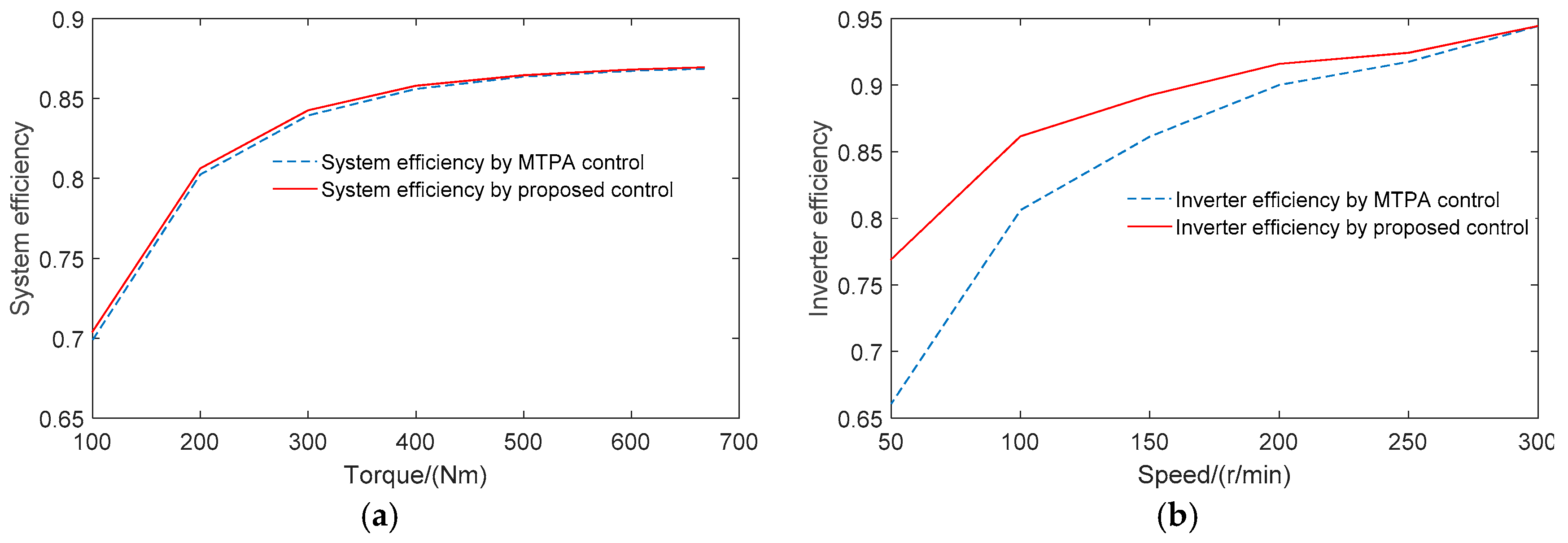
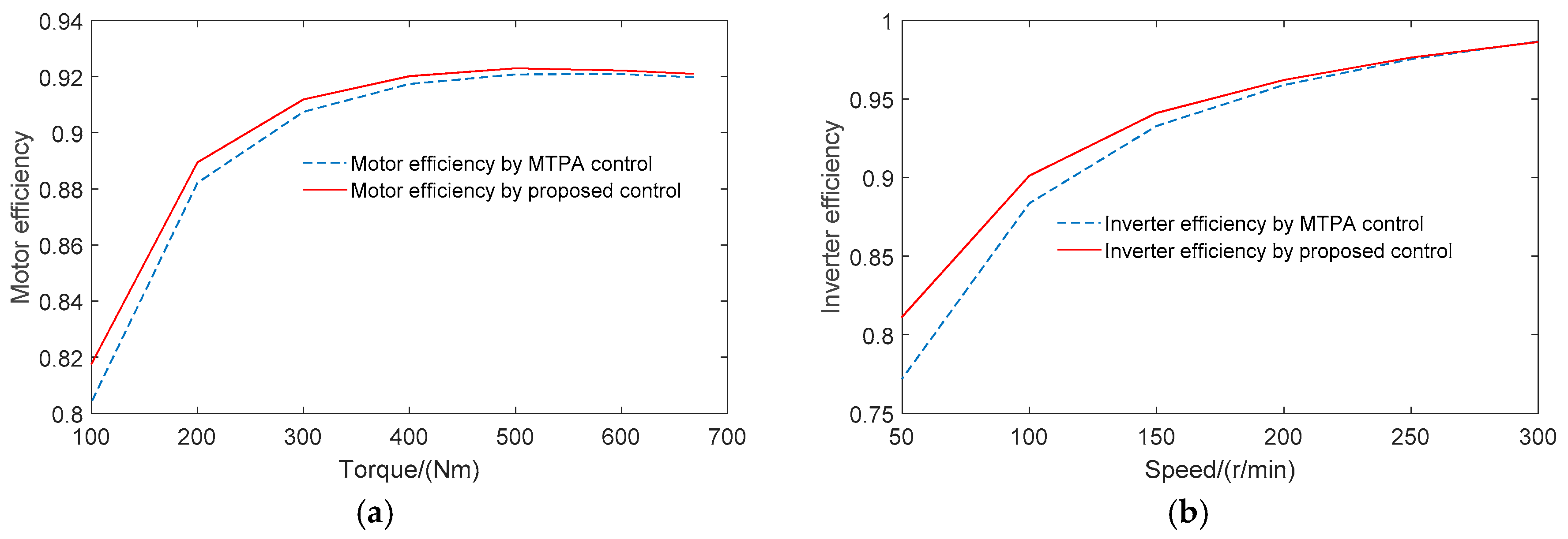
This paper proposes a novel efficiency control strategy to improve the power loss of PMSM drive systema, which can optimize both motor and inverter losses. An accurate nonlinear loss model of a three-phase half-bridge inverter is built to predict the conduction loss and switch loss exactly in the sine-wave PMSM system. This paper applies the double Fourier integral analysis to analytically calculate the fundamental component and harmonics of the inverter output voltage, by which a global motor loss model of the PMSM is established. The global motor loss model can take consideration of both the fundamental motor loss and harmonic motor loss, which shows the coupling relationship between motor loss and inverter loss. Based on the nonlinear inverter loss and global motor loss model, the proposed efficiency optimization control strategy can optimize the motor current and PWM frequency together, by which the PMSM drive system can achieve higher system efficiency compared with traditional control strategies. The loss reduction effect is tested and verified by experiments.

2. Nonlinear Loss Model of Three-Phase Inverter

The most common three-phase inverter for PMSM system is the three-phase half-bridge voltage source inverter, which is shown in Figure 1. The main inverter losses of the PMSM system are conduction loss and switch loss within power devices. To optimize the inverter loss, it is important to build an accurate loss model for the power device. Although there is strongly nonlinearity in the conduction characteristics and switch characteristics of power device, the most common mathematical model of power device loss is a linear model, which is shown in Figure 2.
The linear model of conduction characteristics in IGBT can be expressed as:
U c e s a t = U t 0 + R c e · I c e
where Ucesat is the saturation voltage of power device, Ut0 is the equivalent conduction voltage of power device in rated current In, Rce is equivalent conduction resistance of power device in rated current In.
It can be seen that the traditional linear model of power device can only obtain accurate power device loss at the rated current In. The prediction error will increase when the current of power device deviates from the rated working point. However, the motor current in PMSMs is a sinusoidal current, whose value is changing all the time. Therefore, the traditional linear model will not calculate the inverter loss of PMSM drive system exactly.
To acquire the inverter loss accurately, this paper builds a novel nonlinear model of power devices, which can fit the nonlinear conduction and switch characteristics in each operation condition of a PMSM system. The nonlinear conduction model of IGBT can be shown as:
U c e = a c + b c · I c e + c c · I c e 2
where ac, bc and cc is fitting coefficients of the nonlinear conduction characteristics. From Figure 2, it can be seen that the nonlinear model can accurately fit the power device nonlinear conduction characteristics in the whole operation range of a PMSM system.
As the stator current in PMSM system is changing in a sinusoidal way, the inverter loss will also change at any moment. Therefore, the average conduction loss of IGBT in on current period can be calculated as:
P c o n d u c t i o n _ I G B T = 1 T c u r r e n t 0 T c u r r e n t u c e · i c e d t
where Tcurrent is the period of sinusoidal stator current.
By substituting Equation (2) into Equation (3), the conduction loss of IGBT can be shown as:
P c o n d u c t i o n _ I G B T = a c π I 0 + 2 c c 3 π I 0 3 + b c 4 π I 0 2 + a c 4 M cos φ · I 0 + 2 b c 3 π M cos φ · I 0 2 + 3 c c 16 M cos φ · I 0 3
where I0 is amplitude of stator current, M is the modulation ratio of sine-wave pulse-width modulation (SPWM), and φ is power factor of the PMSM:
M = U 0 U d c 2 = 2 U 0 U d c = 2 u d 2 + u q 2 U d c
The nonlinear conduction model of free-wheeling diode (FWD) can be also expressed as:
U f = a f + b f I f + c f I f 2
where af, bf and cf is fitting coefficients of the nonlinear conduction characteristics of FWD.
Similar to the average conduction loss of IGBT, the average conduction loss of FWD in one current period can be shown as:
P c o n d u c t i o n _ F W D = a f π I 0 + 2 c f 3 π · I 0 3 + b f 4 π · I 0 2 a f 4 M cos φ · I 0 2 b f 3 π M cos φ · I 0 2 3 c f 16 M cos φ · I 0 3
From Equations (4) and (7), the average conduction loss of three-phase half-bridge inverter in one current period can be calculated as:
P c o n d u c t i o n _ i n v e r t e r = 6 · ( P c o n d u c t i o n _ I G B T + P c o n d u c t i o n _ F W D )
The switch characteristics of power devices can also be fitted by proposed nonlinear model. The nonlinear switch-on and switch-off model of IGBT can be expressed as:
E o n = U d c U d c _ t e s t · ( a o n + b o n · I c e + c o n · I c e 2 )
E o f f = U d c U d c _ t e s t · ( a o f f + b o f f · I c e + c o f f · I c e 2 )
where Eon and Eoff are the energy consumption in a switch -on and switch-off process, respectively. Udc is the DC voltage, and Udc_test is the DC voltage when the chip manual tested switching characteristics of the power device. aon, bon, con, aoff, boff and coff is the fitting coefficients of the nonlinear switch characteristics.
Based on the nonlinear model of switch characteristics, the average switch loss of IGBT in one current period can be shown as:
P s w i t c h _ I G B T = f s w U d c U d c _ t e s t · [ 1 4 ( c o n + c o f f ) I 0 2 + 1 π ( b o n + b o f f ) I 0 + 1 2 ( a o n + a o f f ) ]
where fsw is the switch frequency of PWM.
Similar to the switch loss of IGBT, the reverse recovery loss of FWD can be also expressed as:
P r e c _ F W D = f s w U d c U d c _ t e s t · ( 1 4 c r e c I 0 2 + 1 π b r e c I 0 + 1 2 a r e c )
where arec, brec and crec are fitting coefficients of reverse recovery characteristics.
Therefore, the switch loss of inverter can be predicted as:
P s w i t c h _ i n v e r t e r = 6 · ( P s w i t c h _ I G B T + P r e c _ F W D )
and the total loss of power devices in the three-phase half-bridge inverter can be expressed as:
P l o s s _ i n v e r t e r = P c o n d u c t i o n _ i n v e r t e r + P s w i t c h _ i n v e r t e r = 6 { [ a c + a f π I 0 + 2 ( c c + c f ) 3 π I 0 3 + b c + b f 4 π I 0 2 + a c a f 4 M cos φ · I 0 + 2 ( b c b f ) 3 π M cos φ · I 0 2 + 3 ( c c c f ) 16 M cos φ · I 0 3 ] f s w U d c U d c _ t e s t · [ 1 4 ( c o n + c o f f + c r e c ) I 0 2 + 1 π ( b o n + b o f f + b r e c ) I 0 + 1 2 ( a o n + a o f f + a r e c ) ] }

3. Global Loss Model of PMSM

As the PMSM is fed by a three-phase inverter, there must be fundamental current and harmonic current in the PMSM, which is caused by the PMW output voltage of the inverter. The fundamental current drives the motor with the output electromagnet torque and produces a fundamental copper loss and a fundamental iron loss. The harmonic current will impact the stability of the system and creates harmonic copper loss and harmonic iron loss. To optimize the losses of a PMSM drive system, it is important to build an accurate global loss model of the PMSM which consider about both the fundamental motor loss and the harmonic motor loss.

3.1. Fundamental and Harmonic Components of PWM Output Voltage

The PWM output voltage of inverters must induce a harmonic stator current in the PMSM drive system. The harmonic stator current produces a harmonic motor loss which will affect the system efficiency of the PMSM drive system. To build an accurate harmonic loss model of a PMSM, it is necessary to create an analytic method to calculate the harmonic motor current quickly and exactly.
By sine-wave pulse-width modulation (SPWM), the PMSM can obtain a sinusoidal current from the three-phase half-bridge inverter. The typical working principle of SPWM is shown in Figure 3.
The three-phase sinusoidal references displaced in time by 120°, which can be expressed as:
{ U a z = U 0 cos ω 0 t = 1 2 M U d c cos ω 0 t U b z = U 0 cos ( ω 0 t 2 3 π ) = 1 2 M U d c cos ( ω 0 t 2 3 π ) U c z = U 0 cos ( ω 0 t + 2 3 π ) = 1 2 M U d c cos ( ω 0 t + 2 3 π )
where U0 is the amplitude of three-phase sinusoidal references.
To obtain the harmonics of the motor current, the harmonics of the inverter PWM output voltage must be acquired. As it is a complicated problem to measure the harmonics of PWM voltage signal in the SPWM and the harmonic components of PWM signal are always obtained from the time varying simulated signal of PWM output voltage by fast Fourier transform (FFT) analysis. Although the FFT method can conveniently solve the harmonics in a relatively accurate way, the precision of FFT results is limited by the computing capacity and the simulated round-off. The FFT analysis can only obtain the harmonics of PWM signal at a certain working point of the PMSM drive system and cannot acquire the harmonics of the inverter output voltage for the whole operation condition. In contrast, the double Fourier integral analysis can calculate the fundamental component and harmonics of a periodic PWM waveform in an analytic method, which ensures the accuracy of the harmonics and acquires the harmonic voltage of the inverter leg across overall operation condition of the PMSM direct drive system.
The double Fourier integral analysis [30,31] applies two time-varying variables (x(t) and y(t)) to define the PWM signal of inverter output voltage. The x(t) is used to define the carrier signal, which can be shown as:
x ( t ) = ω c t + θ c
where ωc is the carrier angular frequency and θc is the arbitrary phase offset angle for the carrier waveform.
y(t) is applied to delimit the fundamental signal (as the sinusoidal reference signal of SPWM), which can be expressed as:
y ( t ) = ω 0 t + θ 0
where ω0 is the fundamental angular frequency and θ0 is the arbitrary phase offset angle for the fundamental waveform.
The PWM output voltage of the inverter leg can be presented as:
a n ( t ) = f ( x ( t ) , y ( t ) ) = { U d c y ( t ) > x ( t ) 0 y ( t ) x ( t )
where an(t) is defined with respect to the negative DC bus.
By applying double Fourier integral analysis theory, the time-varying function f(x(t), y(t)) can be expressed as a summation of the harmonic components:
f ( x , y ) = A 00 2 + n = 1 { A 0 n cos [ n ( ω 0 t + θ 0 ) ] + B 0 n sin [ n ( ω 0 t + θ 0 ) ] } + m = 1 { A m 0 cos [ m ( ω c t + θ c ) ] + B m 0 sin [ m ( ω c t + θ c ) ] } + m = 1 n = ( n 0 ) { A m n cos [ m ( ω c t + θ c ) + n ( ω 0 t + θ 0 ) ] + B m n sin [ m ( ω c t + θ c ) + n ( ω 0 t + θ 0 ) ] }
where A00 is the DC offset; A0n and B0n are the fundamental component and base-band harmonics; Am0 and Bm0 are the carrier harmonics; Amn and Bmn are side-band harmonics.
The fundamental component and harmonic components of the inverter PWM output signal can be calculated by the double Fourier integral analysis as:
A m n + j B m n = 1 2 π 2 π π π 2 ( 1 + M cos y ) π 2 ( 1 + M cos y ) U d c e [ j ( m x + n y ) ] d x d y
Substituting Equation (15) into Equations (19) and (20), the fundamental and harmonic components of the inverter phase-leg PWM output voltage can be expressed as:
{ u a z ( t ) = 1 2 U d c + 1 2 U d c M cos ω 0 t + 2 U d c π m = 1 1 m J 0 ( m π 2 M ) sin ( m π 2 ) · cos [ m ( ω c t + θ c ) ] + 2 U d c π m = 1 n = n 0 n = { 1 m J n ( m π 2 M ) sin [ ( m + n ) π 2 ] · cos [ m ( ω c t + θ c ) + n ω 0 t ] } u b z ( t ) = 1 2 U d c + 1 2 U d c M cos ( ω 0 t 2 3 π ) + 2 U d c π m = 1 1 m J 0 ( m π 2 M ) · sin ( m π 2 ) · cos [ m ( ω c t + θ c ) ] + 2 U d c π m = 1 n = n 0 n = { 1 m J n ( m π 2 M ) · sin [ ( m + n ) π 2 ] · cos [ m ( ω c t + θ c ) + n ( ω 0 t 2 3 π ) ] } u c z ( t ) = 1 2 U d c + 1 2 U d c M cos ( ω 0 t + 2 3 π ) + 2 U d c π m = 1 1 m J 0 ( m π 2 M ) · sin ( m π 2 ) · cos [ m ( ω c t + θ c ) ] + 2 U d c π m = 1 n = n 0 n = { 1 m J n ( m π 2 M ) sin [ ( m + n ) π 2 ] · cos [ m ( ω c t + θ c ) + n ( ω 0 t + 2 3 π ) ] }
where the constant term 1 2 U d c is caused by the output voltage definition with respect to the negative DC bus. Jn (ξ) is the Bessel function of the nth order.
The fundamental voltage creates the fundamental current in the PMSM, which will bring the fundamental motor loss. Furthermore, the harmonic current caused by the harmonic components of inverter output voltage will generate harmonic motor losses.

3.2. Fundamental Motor Loss

The fundamental motor loss of PMSM can be divided into two parts: the fundamental copper loss and fundamental iron loss. The fundamental copper loss is caused by the fundamental stator current through the stator armature winding. The fundamental iron loss consists of stator iron loss and rotor iron loss. Compared with the stator iron loss, the rotor iron loss is so small that it will have little effect on the loss optimization. Hence this paper only considers the stator iron loss and ignores the rotor iron loss. The fundamental mathematical model of PMSM in the d-axis and q-axis is shown in Figure 4.
The voltage equation and current equation of a PMSM can be expressed as:
{ u d = L 1 d d i d d t + R s _ f i d + L m d d i o d d t n p ω r L m q i o q u q = L 1 q d i q d t + R s _ f i q + L m q d i o q d t + n p ω r ψ f + n p ω r L m d i o d u o d = L m d d i o d d t n p ω r L m q i o q u o q = L m q d i o q d t + n p ω r ψ f + n p ω r L m d i o d
{ i d = i c d + i o d i q = i c q + i o q i c d = 1 R c u o d i c q = 1 R c u o q
where Lmd,q and L1d,q are the stator’s self-inductance and leakage-inductance in the d-axis and q-axis, respectively; Rs_f is defined as the fundamental stator’s resistance without consideration of skin effects and proximity effects, Rc_f is the iron loss resistance for the fundamental iron loss and np is the pole pairs of the PMSM; ωr is the motor rotation speed; ud,q and id,q are the stator’s voltage and the stator’s current, respectively; iod and ioq are the magnetizing currents of the PMSM in the d-axis and q-axis; icd and icq are the exciting current of PMSM in the d-axis and q-axis. Ψf is the flux linkage of permanent magnet.
From the mathematical model of PMSM, the fundamental copper loss can be shown as:
P C u _ f = 3 2 R s _ f ( i d 2 + i q 2 )
where the transformation coefficient 3 2 is caused by the d-q axis current calculation with CLARKE and PARK transmission in the principle which remains the motor flux value invariable.
The fundamental iron loss can be described as:
P F e _ f = 3 2 R c ( i c d 2 + i c q 2 )
The stator iron loss consists of the eddy current loss and hysteresis loss. From the Bertotti iron loss formula [24], the eddy current loss and hysteresis loss per volume can be expressed as:
d P F e = d P F e _ h + d P F e _ d = k h B m 2 f + π 2 σ k d 2 6 B m 2 f 2
where dPFe_h is the eddy current loss per volume and dPFe_d is the hysteresis loss per volume; kh is the coefficients of the hysteresis loss; σ is the conductivity of the material; and kd is the thickness of the lamination. These three parameters are material characteristics of the motor core; f is the frequency, and Bm is the peak value of the magnetic flux density.
Equation (26) shows that there is a linear relationship between hysteresis loss and the frequency of the magnetic field. In addition, the relationship between the eddy current loss and the square of magnetic field frequency is a direct ratio. Therefore, the iron loss resistance can only describe the eddy current loss precisely. To acquire an accurate iron loss, the iron loss resistance Rc is a variable of the rotor speed.
From Equations (24) and (26), the fundamental motor loss of PMSM drive system can be shown as:
P m o t o r _ f = P C u _ f + P F e _ f = 3 2 R s _ f ( i d 2 + i q 2 ) + 3 2 R c ( i c d 2 + i c q 2 ) = 3 2 R s _ f [ ( i o d + L m d d i o d d t n p ω r L m q i o q R c ) 2 + ( i o q + L m q d i o q d t + n p ω r ψ f + n p ω r L m d i o d R c ) 2 ] + 3 2 ( L m d d i o d d t n p ω r L m q i o q ) 2 + ( L m q d i o q d t + n p ω r ψ f + n p ω r L m d i o d ) 2 R c
Equation (27) shows that the fundamental motor loss of a PMSM is a function of d-axis magnetizing current iod, q-axis current magnetizing current ioq and motor speed ωr. The electromagnetic torque can be expressed as:
T e = 3 2 n p [ ψ f i o q + ( L m d L m d ) i o d i o q ]
Therefore, the q-axis current magnetizing current ioq can be acquired by the electromagnetic torque as:
i o q = 2 T e 3 n p [ ψ f + ( L m d L m d ) i o d ]
By substituting Equation (29) into Equation (27), it is seen that the fundamental motor loss of a PMSM drive system is a function a function of the d-axis magnetizing current iod, electromagnetic torque Te and motor speed ωr. For a constant operation condition where the electromagnetic torque and motor speed are given, the fundamental motor loss is only a function of d-axis magnetizing current iod:
P m o t o r _ f = f ( i o d , T e , ω r )

3.3. Harmonic Motor Loss

The harmonic motor loss model of a PMSM is shown in Figure 5.
The harmonic voltage equation and harmonic current equation can be described as:
{ u ˙ a z _ m n = u ˙ o a z _ m n + i ˙ a _ m n · R s _ m n u ˙ b z _ m n = u ˙ o b z _ m n + i ˙ b _ m n · R s _ m n u ˙ c z _ m n = u ˙ o c z _ m n + i ˙ c _ m n · R s _ m n u ˙ o a z _ m n = i ˙ o a _ m n · j ω m n L m s u ˙ o b z _ m n = i ˙ o b _ m n · j ω m n L m s u ˙ o c z _ m n = i ˙ o c _ m n · j ω m n L m s u ˙ n z _ m n = 1 3 ( u ˙ a z _ m n + u ˙ b z _ m n + u ˙ c z _ m n )
{ i ˙ a _ m n = i ˙ o a _ m n + i ˙ c a _ m n i ˙ b _ m n = i ˙ o b _ m n + i ˙ c b _ m n i ˙ c _ m n = i ˙ o c _ m n + i ˙ c c _ m n i ˙ c a _ m n = 1 R c _ m n u ˙ o a z _ m n i ˙ c b _ m n = 1 R c _ m n u ˙ o b z _ m n i ˙ c c _ m n = 1 R c _ m n u ˙ o c z _ m n
where u ˙ a z _ m n , u ˙ b z _ m n and u ˙ c z _ m n are the A-phase, B-phase and C-phase output voltages of the inverter in the n-th fundamental signal and the m-th carrier signal, respectively. u ˙ o a z _ m n , u ˙ o b z _ m n and u ˙ o c z _ m n are the three-phase magnetizing voltages of PMSM in the n-th fundamental signal and the m-th carrier signal. i ˙ a z _ m n i ˙ a z _ m n and i ˙ a z _ m n are the three-phase motor currents in the n-th fundamental signal and the m-th carrier signal. i ˙ a , b , c o z _ m n and i ˙ a , b , c c z _ m n are the three-phase magnetizing currents and exciting currents of PMSM in the n-th fundamental signal and the m-th carrier signal, respectively. Rc_mn is the harmonic iron loss resistance of the n-th fundamental signal and the m-th carrier signal, and the ωmn is the angular frequency of the n-th fundamental signal and the m-th carrier signal, which can be expressed as:
ω m n = n · n p ω r + 2 π m · f s w
Rs_mm is the stator’s resistance in the n-th fundamental signal and the m-th carrier signal which has been considered about skin effect and proximity effect:
R s _ m n = α · R s _ f
where α is the coefficient of skin effect. α is affected by the frequency of harmonic current, which can be described as:
α = d 2 2 δ ber 0 ( d 2 δ ) · bei 0 ( d 2 δ ) ber 0 ( d 2 δ ) · bei ( d 2 δ ) [ ber 0 ( d 2 δ ) ] 2 + [ bei 0 ( d 2 δ ) ] 2
where d is the copper wire diameter of stator windings, and δ is the depth of penetration. The depth of penetration is affected by the current frequency, which is shown in Figure 6.
The terms ber0 and bei0 are the zero order Kelvin function, which can be expressed as:
{ ber 0 ( u ) j bei 0 ( u ) = J 0 ( u e j 3 π 4 ) ber 0 ( u ) j bei 0 ( u ) = e j 3 π 4 · J 1 ( u e j 3 π 4 )
From Equations (31) and (32), the amplitude of three-phase currents of PMSM can be described as:
I s _ m n = | ( 2 · u ˙ a z _ m n u ˙ b z _ m n u ˙ c z _ m n ) · j ω m n L m s · R c 3 [ R c · R s _ m n + j ω m n L m s · ( R c + R s _ m n ) ] |
where Is_mn is the amplitude of three-phase magnetizing currents, and Is_ms is the amplitude of three-phase currents.
Therefore, the harmonic copper loss can be expressed as:
P C u _ h = 3 [ n = 2 I s _ 0 n 2 · R s _ m n + m = 1 n = n 0 I s _ m n 2 · R s _ m n ]
From Equation (26), it can be seen that the harmonic iron loss is affected by the frequency of magnetic field and amplitude of magnetic flux density. As the magnetic flux density is different between stator tooth and yoke, the harmonic iron loss can be presented as:
P F e _ m n = P F e _ t _ m n + P F e _ y _ m n = d P F e _ t _ m n · V t + d P F e _ y _ m n · V y
where Vt and Vy is the total volume of stator tooth and stator yoke, respectively. dPFe_t_mn is the iron loss density of the n-th fundamental signal and the m-th carrier signal in the stator tooth, which is shown as:
d P F e _ t _ m n = d P F e _ h _ t _ m n + d P F e _ d _ t _ m n = k h B m _ t _ m n 2 f m n + π 2 σ k d 2 6 B m _ t _ m n 2 f m n 2
where fmn is the frequency of the n-th fundamental signal and the m-th carrier signal, and Bm_t_mn is the amplitude of harmonic magnetic flux density in the stator tooth:
B m _ t _ m n = Φ m n α i · Q · S t 2 n p
where αi is the pole arc factor, Q is the number of slot, St is the physical area of a stator tooth.
As the harmonic fluxes can be obtained from harmonic flux linkage as:
Φ m n = Ψ m n N 1 · K d p _ m n
where N1 is the number of turns per phase, and Kdp_mn is the harmonic winding factor.
Therefore, from Equations (40)–(42), the harmonic iron loss in the stator tooth can be expressed as:
P F e _ t _ m n = [ k h ( Ψ m n N 1 · K d p _ m n α i Q S t 2 n p ) 2 f m n + π 2 σ k d 2 6 ( Ψ m n N 1 · K d p _ m n α i Q S t 2 n p ) 2 f m n 2 ] · V t
Similar to the calculation of magnetic flux density in the stator tooth, the magnetic flux density in the stator yoke can be:
B m _ y _ m n = Ψ m n 1 2 N 1 · K d p _ m n · S y
where Sy is the physical areas of a stator tooth.
From Equations (39) and (44), the harmonic iron loss in the stator yoke can be calculated as:
P F e _ y _ m n = [ k h ( Ψ m n 1 2 N 1 · K d p _ m n · S y ) 2 f m n + π 2 · σ · k d 2 6 ( Ψ m n 1 2 N 1 · K d p _ m n · S y ) 2 f m n 2 ] · V y
Therefore, the harmonic iron loss can be expressed as:
P F e _ m n = P F e _ t _ m n + P F e _ y _ m n = [ k h ( L m s I o s _ m n N 1 · K d p _ m n α i · Q · S t 2 n p ) 2 f m n + π 2 σ k d 2 6 ( L m s I o s _ m n N 1 K d p _ m n α i · Q · S t 2 n p ) 2 f m n 2 ] · V t + [ k h ( L m s I o s _ m n 1 2 N 1 · K d p _ m n · S y ) 2 f m n + π 2 σ k d 2 6 ( L m s I o s _ m n 1 2 N 1 · K d p _ m n · S y ) 2 f m n 2 ] · V y
As the harmonic iron loss can also be expressed as:
P F e _ m n = 3 R c _ m n · I c s _ m n 2 = 3 ( ω m n · I o s _ m n · L m s ) 2 R c _ m n
Substituting Equation (46) to Equation (47), the harmonic iron loss resistance can be obtained as:
R c _ m n = 3 π 2 · f m n 2 · N 1 2 · K d p _ m n 2 ( k h · f m n + π 2 σ k d 2 6 f m n 2 ) · ( n p 2 V t α i 2 Q 2 S t 2 + V y S y 2 )
From Equation (48), it can be seen that the harmonic iron resistance is more susceptible to the frequency of the harmonic signals. To obtain the accurate harmonic iron loss, the harmonic iron loss should be calculated in each harmonic component of the PWM voltage.
Based on the harmonic loss model, the amplitude of the three exciting currents of PMSM can be described as:
I c s _ m n = | ( u ˙ b z _ m n + u ˙ c z _ m n 2 · u ˙ a z _ m n ) · ω m n 2 L m s 2 · R c 3 [ R c · R s _ m n + j ω m n L m s · ( R c + R s _ m n ) ] · ( R c + j ω m n L m s ) |
Hence, similar to the harmonic copper loss, the harmonic iron loss can be expressed as:
P F e _ h = 3 [ n = 2 I c s _ 0 n 2 · R c + m = 1 n = n 0 I c s _ m n 2 · R c ]
Therefore, from the harmonic copper loss model and harmonic iron loss model, the harmonic motor loss of PMSM drive system can be shown as:
P m o t o r _ h = P C u _ h + P F e _ h = 3 [ n = 2 I s _ 0 n 2 · R s _ m n + m = 1 n = n 0 I s _ m n 2 · R s _ m n + n = 2 I c s _ 0 n 2 · R c + m = 1 n = n 0 I c s _ m n 2 · R c ]

3.4. Global Loss Model of PMSM

Based on the fundamental motor loss model and harmonic motor loss model, the global loss model can be expressed as:
P l o s s _ m o t o r = P m o t o r _ f + P m o t o r _ h = 3 2 R s _ f [ ( i o d + L m d d i o d d t n p ω r L m q i o q R c ) 2 + ( i o q + L m q d i o q d t + n p ω r ψ f + n p ω r L m d i o d R c ) 2 ] + 3 2 ( L m d d i o d d t n p ω r L m q i o q ) 2 + ( L m q d i o q d t + n p ω r ψ f + n p ω r L m d i o d ) 2 R c + 3 [ n = 2 I s _ 0 n 2 · R s _ m n + m = 1 n = n 0 I s _ m n 2 · R s _ m n + n = 2 I c s _ 0 n 2 · R c + m = 1 n = n 0 I c s _ m n 2 · R c ]
By substituting Equations (22) and (29) to Equation (52), the global motor loss can be described as:
P l o s s _ m o t o r = P m o t o r _ f + P m o t o r _ h = f ( i o d , i o q , ω r ) + f ( M , ω r , f s w ) = f ( i o d , T e , ω r ) + f ( i o d , T e , ω r , f s w )
Equation (53) shows that the fundamental component of the global motor loss is a function of d-axis magnetizing current iod, electromagnetic torque Te and motor speed ωr, while the harmonic components of global motor loss are a function of d-axis magnetizing current iod, electromagnetic torque Te, motor speed ωr and PWM frequency fsw.

4. System Loss Optimized Control for PMSM Drive System

From Equations (14) and (53), the system loss of PMSM drive system can be expressed as:
P l o s s _ s y s t e m = P l o s s _ i n v e r t e r + P l o s s _ m o t o r = 6 { [ a c + a f π I 0 + 2 ( c c + c f ) 3 π I 0 3 + b c + b f 4 π I 0 2 + a c a f 4 M cos φ I 0 + 2 ( b c b f ) 3 π M cos φ I 0 2 + 3 ( c c c f ) 16 M cos φ I 0 3 ] f s w U d c U d c _ t e s t · [ 1 4 ( c o n + c o f f + c r e c ) I 0 2 + 1 π ( b o n + b o f f + b r e c ) I 0 + 1 2 ( a o n + a o f f + a r e c ) ] } + 3 2 R s _ f [ ( i o d + L m d d i o d d t n p ω r L m q i o q R c ) 2 + ( i o q + L m q d i o q d t + n p ω r ψ f + n p ω r L m d i o d R c ) 2 ] + 3 2 ( L m d d i o d d t n p ω r L m q i o q ) 2 + ( L m q d i o q d t + n p ω r ψ f + n p ω r L m d i o d ) 2 R c + 3 [ n = 2 I s _ 0 n 2 · R s _ m n + m = 1 n = n 0 I s _ m n 2 · R s _ m n + n = 2 I c s _ 0 n 2 · R c + m = 1 n = n 0 I c s _ m n 2 · R c ]
Equation (54) shows that the system loss of a PMSM drive system is so complicated that it is impossible to directly optimize the system loss by an analytical method. Therefore, to maximize the system efficiency of PMSM system, the system loss can be divided into two parts: one part is the loss only affected by motor operation state and the other part is the loss affected by motor and inverter operation state, which can be shown as:
P l o s s _ s y s t e m = P M o t o r _ a f f e c t _ l o s s + P D o u b l e _ a f f e c t _ l o s s
where the loss only affected by motor state in the steady state can be expressed as:
P M o t o r _ a f f e c t _ l o s s = 6 ( a c + a f ) π I 0 + 4 ( c c + c f ) π I 0 3 + 6 ( b c + b f ) 4 π I 0 2 + 3 ( a c a f ) 2 M cos φ · I 0 + 4 ( b c b f ) π M cos φ · I 0 2 + 9 ( c c c f ) 8 M cos φ · I 0 3 + 3 2 R s _ f [ ( i o d n p ω r L m q i o q R c ) 2 + ( i o q + n p ω r ψ f + n p ω r L m d i o d R c ) 2 ] + 3 2 ( n p ω r L m q i o q ) 2 + ( n p ω r ψ f + n p ω r L m d i o d ) 2 R c = P c o n d u c t i o n _ i n v e r t e r + P m o t o r _ f
and the loss affected by motor and inverter operation state in the steady state can be shown as:
P D o u b l e _ a f f e c t _ l o s s = f s w U d c U d c _ t e s t · [ 3 2 ( c o n + c o f f + c r e c ) I 0 2 + 6 π ( b o n + b o f f + b r e c ) I 0 + 3 ( a o n + a o f f + a r e c ) ] + 3 [ n = 2 I s _ 0 n 2 · R s _ m n + m = 1 n = n 0 I s _ m n 2 · R s _ m n + n = 2 I c s _ 0 n 2 · R c + m = 1 n = n 0 I c s _ m n 2 · R c ] = P s w i t c h _ i n v e r t e r + P m o t o r _ h
Based on the system loss model, this paper proposes a system efficiency improvement control which aims to optimize the system loss and improve the system efficiency of a PMSM system over the whole operation condition range of EVs. As the system loss model is too complex to solve, the proposed control strategy optimizes the system efficiency by minimizing the loss affected by motor operation condition (PMotor_affect_loss) and the loss affected by motor and inverter operation state (PDouble_affect_loss).
Equation (57) shows that PMotor_affect_loss is only affected by the motor drive parameters (iod, ioq, M, ωr). By substituting Equations (5), (15) and (22) into Equation (57), the PMotor_affect_loss can be simplified as:
P M o t o r _ a f f e c t _ l o s s = P c o n d u c t i o n _ i n v e r t e r + P m o t o r _ f = f ( i o d , T e , ω r )
Equation (58) shows that the loss PMotor_affect_loss is a function of d-axis magnetizing current iod, electromagnetic torque Te and motor speed ωr. Therefore, for each certain operation point, there must be an optimal d-axis magnetizing current iod*, which can minimize the loss affected by motor state. The optimal d-axis magnetizing current iod* can be expressed as:
P M o t o r _ a f f e c t _ l o s s i o d | i o d = i o d T e = c o n s t , ω r = c o n s t = 0
By keeping the d-axis magnetizing current iod at the optimal value, the proposed system efficiency improvement control can minimize the loss affected by motor operation condition at each working point of the PMSM system in EVs.
There are two constraints for the optimal d-axis magnetizing current iod*. One is that, in order to protect permanent magnet, the optimal d-axis magnetizing current should smaller than the maximum flux-weakening current, which can be shown as:
| i o d | | i d _ f l u x w e a k e n i n g _ m a x |
where id_fluxweakening_max is the max flux-weakening current.
When the d-axis current is larger than the maximum flux weakening current, the magnetic performance of the permanent magnet will be damaged beyond retrieval. Therefore, to maintain the system stability of PMSM drive system, the d-axis current should not exceed the max flux-weakening current.
The other one is the total motor current should smaller than the maximum value of inverter current, which can be expressed as:
i d 2 + i q 2 I s _ m a x 2
where Is_max is the maximum allowable current of inverter.
When the d-axis magnetizing current iod is controlled at iod*, the motor operation state is determined. Therefore, the second part of system loss PDouble_affect_loss will be only affected by the PWM frequency fsw of the power converter, which is shown as:
P D o u b l e _ a f f e c t _ l o s s = P s w i t c h _ i n v e r t e r + P m o t o r _ h = f ( f s w )
The PWM frequency fsw impacts on the switching loss of the inverter and harmonics of motor loss. The high carrier to noise ratio (CTNR) in the higher PWM frequency will decrease the harmonics of the motor current, which will reduce the harmonic motor loss. However, an increasing switch loss will be caused by the higher PWM frequency. Therefore, it is significant to obtain the optimum PWM frequency fsw* which can achieve the minimum value of switching loss and harmonic motor loss.
However, the PWM frequency fsw not only has an important influence on the loss affected by the motor and inverter operation state, but also affects the system stability of the PMSM system in EVs. As mentioned above, the PWM output voltage of the inverter must cause the harmonic current in the PMSM and the harmonic current will be greater in the low CTNR with small PWM frequency, which may seriously affect the stability of the PMSM system. In order to ensure the security and stability of the PMSM system, the PWM frequency must be carefully chosen by which the CTNR will meet the requirement of current total harmonic distribution (THD).
Therefore, the optimum PWM frequency fsw* can be obtained by the proposed system efficiency improvement control as:
{ I 0 n = 1 I c s _ 0 n 2 · R c + m = 1 n = n 0 I c s _ m n 2 · R c | f s w = f s w T e = c o n s t , ω r = c o n s t T H D m a x Min ( P s w i t c h _ i n v e r t e r + P m o t o r _ h ) = Min { f s w U d c U d c _ t e s t · [ 3 2 ( c o n + c o f f + c r e c ) I 0 2 + 6 π ( b o n + b o f f + b r e c ) I 0 + 3 ( a o n + a o f f + a r e c ) ] + 3 [ n = 2 I s _ 0 n 2 · R s _ m n + m = 1 n = n 0 I s _ m n 2 · R s _ m n + n = 2 I c s _ 0 n 2 · R c + m = 1 n = n 0 I c s _ m n 2 · R c ] }
As there are infinite sums in the calculation formula of harmonic motor loss, it is too complicated to solve optimum PWM frequency fsw*. Therefore, this paper applies the genetic algorithm (GA) to improve calculation efficiency of the optimized PWM frequency. The GA is a random global search method based on applying the principle with survival of the fittest solution which selects a generation by fitness functions and manipulates the next generation by genetic operators. The flowchart in Figure 7 shows the steps applied to design optimized PWM frequency by the GA.
The GA uses the goal of minimizing the loss affected by the motor and inverter operation state as the objective function for parameter tuning. The function of the second term is to penalize the THD of the motor current. By the GA, the optimized PWM frequency fsw* of each operation condition for EVs can be obtained in a simple and fast way. Based on the optimization of the two parts of the system loss, the system efficiency improvement control can minimize the system loss by adjusting the magnetizing d-axis current and PWM frequency at the optimum value over the whole operation range. The proposed control strategy can increase the efficiency of the PMSM drive system and reduce the energy consumption of EVs, by which the endurance mileage of EVs in one charge will be significantly improved. The structure diagram of the proposed system loss optimized control system is shown in Figure 8.

5. Experimental Results and Discussion

Figure 9 shows an experimental platform of a PMSM drive system which is designed and implemented to verify the performance of the proposed system loss optimized control strategy.
The motor in the test platform is a 21 kW outer rotor surface PMSM, which parameters are listed in the Table 1. The 45 kW PMSM inverter is based on the Si-IGBT power devices to drive the outer rotor PMSM. The Si-IGBT modules used in the experimental platform are the FF300R06KE3, and the fitted coefficients of FF300R06KE3 are shown in the Table 2.
The 330 kW, 8000 r/min special dynamometer for HEVs/EVs are applied as the mechanical load for the outer rotor PMSM to simulate the operation load characteristics of EVs. The power converter for PMSM is controlled by a TMS320F28335-based DSP controller (produced by Texas Instruments Company, Dallas, TX, USA). The controller applies the proposed system efficiency improvement control method and traditional MTPA control strategy on the PMSM drive system. The experimental results of the PMSM drive system by MTPA control are shown in Table 3 and Table 4. Table 3 shows the experimental results of the Si-IGBT-based PMSM drive system with different power at rated torque, and Table 4 shows the experimental results with different torque at rated speed.
Table 5 and Table 6 show the performance of the PMSM drive system with the proposed control strategy. The experimental results at rated torque are shown in Table 5, and the experimental results at different torque is presented in Table 6.
Table 5 and Table 6 show that the proposed control strategy can improve the efficiency of the PMSM direct drive system at each operation condition. Compared with traditional MTPA control, Figure 10 shows that the proposed system efficiency improvement control can decrease both the motor loss and inverter loss.
Figure 10 shows that the system efficiency improvement control strategy can decrease the motor loss and increase the 0.94% motor efficiency at rated speed. Furthermore, the proposed control strategy can also reduce the losses of power converter, by which the inverter efficiency can be added at 10.85% at rated torque. Figure 11 shows the system efficiency by the traditional MTPA control method and the proposed control strategy.
It can be seen that the system efficiency improvement control method can obtain higher system efficiency than the traditional MTPA control over the whole operation condition range of the PMSM direct drive system. The proposed control strategy can increase the system efficiency by 0.54% at rated speed and improve the efficiency of PMSM drive system by 8.38% at rated torque.
To verify the efficiency optimization performance of the proposed system efficiency improvement respect to conventional MTPA control, this paper also designs a SiC-MOSFETs-based power converter which is shown in Figure 12.
The SiC-MOSFETs based power converter utilizes SiC-MOSFET modules (CAS300M12BM2) as the power devices which can obtain lower switching losses than Si-IGBT. The fitted coefficients of CAS300M12BM2 are shown in Table 7.
The experimental results of the PMSM system drivne by the SiC-MOSFETs based power converter are shown in Table 8, Table 9, Table 10 and Table 11. Table 8 and Table 9 show the performance of the PMSM drive system under the traditional MTPA control. Table 8 shows the experimental results of the PMSM drive system at rated torque, and Table 9 shows the performance of the PMSM drive system at rated speed.
Table 10 and Table 11 show the experimental results of the SiC-MOSFETs-based PMSM drive system by the proposed system efficiency improvement control strategy. The experimental results at rated torque are shown in Table 10, and the experimental results at different torque are presented in Table 11.
From Table 10 and Table 11, it can be seen that proposed system efficiency improvement control method can improve the efficiency performance of the PMSM drive system over the whole operation range. Figure 13 shows that, the proposed control strategy can reduce both the losses of PMSM and losses of power converter, by which the system efficiency is obviously improved.
Figure 13 shows that the proposed system efficiency improvement control method can reduce the losses of PMSM and increase the motor efficiency at 1.36% at rated speed. In addition, the proposed control can also decrease the inverter losses, by which the efficiency of power converter can be raised by 3.94% at rated torque.
Figure 14 shows the system efficiency of the SiC-MOSFETs-based PMSM drive system under the traditional MTPA control and the proposed system efficiency improvement control strategy.
It can be seen from Figure 14 that the proposed control strategy can achieve better system efficiency than the conventional MTPA control for each operation condition of PMSM direct drive system. The system efficiency is increased by 0.93% at rated speed and improved by 3.10% at rated torque. Figure 15 shows the system efficiency difference between the Si-IGBTs-based PMSM direct drive system and the SiC-MOSFETs-based PMSM direct drive system.
Figure 15 shows that, as a result of the use of SiC-MOSFETs, the system efficiency of the SiC-MOSFET-based PMSM direct drive system is higher than the Si-IGBT-based system in the both MPTA control and proposed system efficiency improvement control. As the SiC-MOSFET power device has lower switching losses than the Si-IGBT power device, the switching losses’ ratio of system losses in the SiC-MOSFET-based PMSM is lower than that in the Si-IGBT-based PMSM system. Therefore, it can be seen that, compared with conventional the SiC-MOSFET-based PMSM system, the proposed control strategy can have better efficiency optimized performance in the conventional Si-IGBT-based PMSM direct drive system.
The experimental results show that the proposed system efficiency improvement control strategy aims to decrease the system losses by optimizing both motor losses and inverter losses, and improves the system efficiency under each operational condition. The PMSM direct drive system with either Si-IGBT or SiC-MOSFET can achieve lower energy consumption by using the proposed control method over the whole operation range of EVs.

6. Conclusions

This paper designs a novel efficiency optimization control named system efficiency improvement control strategy for the PMSM direct drive systems which aims to increase the system efficiency by optimizing the motor losses and inverter losses together. As the traditional linear loss model can only accurately determine the inverter loss at rated operation conditions, a nonlinear inverter loss model which applies polynomials to fit the nonlinear characteristics of the power device is built in this paper. The proposed nonlinear model can obtain a more accurate loss of power converter is obtained over the whole operation condition of PMSM drive system. As the PMSM is fed by the switching-mode inverter, the PWM output voltage of inverter will cause the harmonic current in the PMSM, which will lead harmonic motor loss and affect the system stability. To obtain a more accurate harmonic motor loss, this paper uses the double Fourier integral analysis to analytically calculate the fundamental component and harmonics of inverter output voltage, by which the fundamental motor losses and harmonic motor loss can be accurately analyzed. From the inverter loss model and motor loss model, this paper presents a whole-frequency-domain system loss model which consider both fundamental loss and harmonic loss. Based on the whole-frequency-domain system loss model, this paper applies the system efficiency improvement control strategy to optimize the motor current and PWM frequency together. The PMSM direct drive system can achieve higher efficiency without serious influence on the system stability under each operational condition of EVs. Compared with the traditional MTPA control strategy, the proposed control method can improve the system efficiency by 3.1% in the SiC-MOSFET-based PMSM direct drive system and by 8.38% in the Si-IGBT-based PMSM drive system.
Both theoretical analysis and experimental results prove that, with the consideration of the coupling relationship between the power converter and PMSM, the proposed efficiency optimization control strategy can synthetically optimize the fundamental motor loss, harmonic motor loss and inverter loss. Without serious influence on the system stability, the system efficiency improvement control strategy can minimize the system losses. By decreasing the energy consumption of the PMSM system, the proposed optimization control method will significantly increase the endurance mileage in one charge and improve the performance of EVs. This paper provides a more accurate whole-frequency-domain system loss model, and as the control strategy is based on the system loss model, the optimized performance is limited by the motor parameters and inverter parameters. The experimental results show that although the SiC-MOSFET-based PMSM direct drive system has higher system efficiency than the Si-IGBT-based PMSM drive system, the Si-IGBT-based system has better optimized performance in the proposed optimization control method than the SiC-MOSFET- based system. Therefore, from point of view about reducing the energy consumption, the Si-IGBT- based system is more suitable for the urban complex traffic situation. Otherwise, the SiC-MOSFET- based system is more suitable for high speed road conditions and industrial application. Future research will attempt to find a establish a optimization design method which can optimize the motor parameters, inverter parameter and control method from a systems perspective. According to the operation condition characteristics, the system parameters and control method should be more specifically designed. After the system optimization of the parameter and control method, the performance of the power system in EVs will be great improved and the EVs will have a wider scope of application in modern society.

Acknowledgments

This work was supported in part by the National Natural Science Foundation of China (No. 51677041) and in part by the State Key Program of National Natural Science Foundation of China (No. 51537002) and in part by the National key S&T Special Projects of China (No. 2012ZX045001051).

Author Contributions

Chengming Zhang and Liyi Li designed the system loss model of the PMSM direct drive system, Qingbo Guo designed the proposed system efficiency improvement control method, Mingyi Wang designed the experimental platform of the PMSM drive system and Tiecheng Wang analyzed the experimental data.

Conflicts of Interest

The authors declare no conflict of interest. The founding sponsors had no role in the design of the study; in the collection, analyses, or interpretation of data; in the writing of the manuscript, and in the decision to publish the results.

References

  1. Gu, W.; Zhu, X.; Quan, L.; Du, Y. Design and Optimization of Permanent Magnet Brushless Machines for Electric Vehicle Applications. Energies 2015, 8, 13996–14008. [Google Scholar] [CrossRef]
  2. Sui, Y.; Zheng, P.; Wu, F.; Yu, B.; Wang, P.; Zhang, J. Research on a 20-Slot/22-Pole Five-Phase Fault-Tolerant PMSM Used for Four-Wheel-Drive Electric Vehicles. Energies 2014, 7, 1265–1287. [Google Scholar] [CrossRef]
  3. Cheng, M.; Sun, L.; Buja, G.; Song, L. Advanced Electrical Machines and Machine-Based Systems for Electric and Hybrid Vehicles. Energies 2015, 8, 9541–9564. [Google Scholar] [CrossRef]
  4. Wang, T.; Wang, H. Research on an Integrated Hydrostatic-Driven Electric Generator with Controllable Load for Renewable Energy. Energies 2017, 10, 1299. [Google Scholar] [CrossRef]
  5. Liu, X.; Chen, H.; Zhao, J.; Belahcen, A. Research on the Performances and Parameters of Interior PMSM Used for Electric Vehicles. IEEE Trans. Ind. Electron. 2016, 63, 3533–3545. [Google Scholar] [CrossRef]
  6. Chu, L.; Jia, Y.-F.; Chen, D.-S.; Xu, N.; Wang, Y.-W.; Tang, X.; Xu, Z. Research on Control Strategies of an Open-End Winding Permanent Magnet Synchronous Driving Motor (OW-PMSM)-Equipped Dual Inverter with a Switchable Winding Mode for Electric Vehicles. Energies 2017, 10, 616. [Google Scholar] [CrossRef]
  7. Sant, A.V.; Khadkikar, V.; Xiao, W.; Zeineldin, H.H. Four-Axis Vector-Controlled Dual-Rotor PMSM for Plug-in Electric Vehicles. IEEE Trans. Ind. Electron. 2015, 62, 3202–3212. [Google Scholar] [CrossRef]
  8. Fodorean, D.; Sarrazin, M.M.; Marţiş, C.S.; Anthonis, J.; Van der Auweraer, H. Electromagnetic and Structural Analysis for a Surface-Mounted PMSM Used for Light-EV. IEEE Trans. Ind. Appl. 2016, 52, 2892–2899. [Google Scholar] [CrossRef]
  9. Zhao, J.; Gu, Z.; Li, B.; Liu, X.; Li, X.; Chen, Z. Research on the Torque and Back EMF Performance of a High Speed PMSM Used for Flywheel Energy Storage. Energies 2015, 8, 2867–2888. [Google Scholar] [CrossRef]
  10. Gerlach, T.; Steckel, R.; Hubert, T.; Kremser, A. Eddy current loss analysis in permanent magnets of synchronous machines. In Proceedings of the 2016 6th International Electric Drives Production Conference (EDPC), Nuremberg, Germany, 30 November–1 December 2016; pp. 246–252. [Google Scholar]
  11. Liu, Y.; Tong, C.; Bai, J.; Yu, S.; Tong, W.; Fu, W. Optimization of an 80 kW Radial-Radial Flux Compound-Structure Permanent-Magnet Synchronous Machine Used for HEVs. IEEE Trans. Magn. 2011, 47, 2399–2402. [Google Scholar] [CrossRef]
  12. Dinh, B.M.; Tien, H.M. Mathematical Model for MTPA Control of Permanent-Magnet Synchronous Motor in Stator Flux Linkage Synchronous Frame. IEEE Trans. Ind. Appl. 2015, 51, 3620–3628. [Google Scholar]
  13. Thomas, F.; Kay, H. Design and optimization of an IPMSM with fixed outer dimensions for application in HEVs. In Proceedings of the IEEE International Electric Machines and Drives Conference, Miami, FL, USA, 3–6 May 2009; pp. 887–892. [Google Scholar]
  14. Shinohara, A.; Inoue, Y.; Morimoto, S.; Sanada, M. Maximum Torque Per Ampere Control in Stator Flux Linkage Synchronous Frame for DTC-Based PMSM Drives Without Using q-Axis Inductance. IEEE Trans. Ind. Appl. 2017, 53, 3663–3671. [Google Scholar] [CrossRef]
  15. Preindl, M.; Bolognani, S. Optimal State Reference Computation with Constrained MTPA Criterion for PM Motor Drives. IEEE Trans. Power Electron. 2015, 30, 4524–4535. [Google Scholar] [CrossRef]
  16. Inoue, T.; Inoue, Y.; Morimoto, S.; Sanada, M. Maximum Torque per Ampere Control of a Direct Torque-Controlled PMSM in a Stator Flux Linkage Synchronous Frame. IEEE Trans. Ind. Appl. 2016, 52, 2630–2637. [Google Scholar] [CrossRef]
  17. Sepulchre, L.; Fadel, M.; Pietrzak-David, M.; Porte, G. Flux-weakening strategy for high speed PMSM for vehicle application. In Proceedings of the 2016 International Conference on Electrical Systems for Aircraft, Railway, Ship Propulsion and Road Vehicles & International Transportation Electrification Conference (ESARS-ITEC), Toulouse, France, 2–4 November 2016; pp. 1–7. [Google Scholar]
  18. Guo, Q.; Zhang, C.; Li, L.; Zhang, J.; Liu, J.; Wang, T. Efficiency Optimization Control of Permanent-Magnet Synchronous Machines for Electric Vehicle Traction Systems. In Proceedings of the 2016 IEEE Vehicle Power and Propulsion Conference (VPPC), Hangzhou, China, 17–20 October 2016; pp. 1–5. [Google Scholar]
  19. Moussa, M.F.; Helal, A.; Gaber, Y.; Youssef, H.A. Unity Power Factor control of permanent magnet motor drive system. In Proceedings of the 12th International Middle-East Power System Conference, Aswan, Egypt, 12–15 March 2008; pp. 360–367. [Google Scholar]
  20. Wu, F.; Wan, S.-M.; Huang, S.-H. Unity power factor control for PMSM position sensorless drive. In Proceedings of the International Conference on Electrical Machines and Systems, Wuhan, China, 17–20 October 2008; pp. 1618–1620. [Google Scholar]
  21. Xiao, X.; Zhang, S.; Ding, Y.; Song, Y. Control Method of PMSM Driving System with Small DC-Link Capacitor. In Proceedings of the 2017 IEEE Energy Conversion Congress and Exposition (ECCE), Cincinnati, OH, USA, 1–5 October 2017; pp. 1925–1931. [Google Scholar]
  22. Lee, J.; Nam, K.; Choi, S.; Kwon, S. A Lookup Table Based Loss Minimizing Control for FCEV Permanent Magnet Synchronous Motors. In Proceedings of the 2007 IEEE Vehicle Power and Propulsion Conference, Arlington, TX, USA, 9–12 September 2007; pp. 175–179. [Google Scholar]
  23. Lemmens, J.; Vanassche, P.; Driesen, J. Optimal Control of Traction Motor Drives under Electrothermal Constraints. IEEE J. Emerg. Sel. Top. Power Electron. 2014, 2, 249–263. [Google Scholar] [CrossRef]
  24. Ni, R.G.; Xu, D.G.; Wang, G.L.; Ding, L.; Zhang, G.Q.; Qu, L.Z. Maximum Efficiency Per Ampere Control of Permanent-Magnet Synchronous Machines. IEEE Trans. Ind. Electron. 2015, 62, 2135–2143. [Google Scholar] [CrossRef]
  25. Aguirre, M.; Madina, P.; Poza, J.; Aranburu, A.; Nieva, T. Analysis and comparison of PWM modulation methods in VSI-Fed PMSM drive systems. In Proceedings of the 2012 XXth International Conference on Electrical Machines, Marseille, France, 2–5 September 2012; pp. 851–857. [Google Scholar]
  26. Wang, Y.; Wen, X.; Zhao, F. Vector control of six-phase PMSMs with selective harmonic elimination PWM. In Proceedings of the 2014 IEEE Conference and Expo Transportation Electrification Asia-Pacific (ITEC Asia-Pacific), Beijing, China, 31 August–3 September 2014; pp. 1–6. [Google Scholar]
  27. Zhang, Z.; Ge, X.; Tian, Z.; Zhang, X.; Tang, Q.; Feng, X. A PWM for Minimum Current Harmonic Distortion in Metro Traction PMSM with Saliency Ratio and Load Angle Constraints. IEEE Trans. Power Electron. 2017, 9. [Google Scholar] [CrossRef]
  28. Kravaritis, E.; Sourkounis, C. Efficiency analysis of pumps drives for Space Vector PWM and Hysteresis Band PWM with on operation transaction of the control method. In Proceedings of the 2017 25th Mediterranean Conference on Control and Automation (MED), Valletta, Malta, 3–6 July 2017; pp. 473–477. [Google Scholar]
  29. Liang, W.; Wang, J.; Luk, P.C.; Fang, W.; Fei, W. Analytical Modeling of Current Harmonic Components in PMSM Drive with Voltage-Source Inverter by SVPWM Technique. IEEE Trans. Energy Convers. 2014, 29, 673–680. [Google Scholar] [CrossRef]
  30. Holmes, D.G.; Lipo, T.A. Pulse Width Modulation for Power Converters: Principles and Practice; EI-Hawart, M.E., Ed.; Wiley-IEEE Press: New York, NY, USA, 2003; pp. 276–353. [Google Scholar]
  31. Yamazaki, K.; Seto, Y. Iron loss analysis of interior permanent-magnet synchronous motors-variation of main loss factors due to driving condition. IEEE Trans. Ind. Appl. 2006, 42, 1045–1052. [Google Scholar] [CrossRef]
Figure 1. Typical topology of three-phase voltage source inverter.
Energies 10 02030 g001
Figure 2. Linear model and nonlinear model.
Energies 10 02030 g002
Figure 3. Typical working principle of SPWM in the three-phase PMSM drive system.
Energies 10 02030 g003
Figure 4. Fundamental mathematical model of PMSM. (a) Fundamental motor model in the d-axis; (b) fundamental motor model in the q-axis.
Energies 10 02030 g004
Figure 5. Harmonic motor loss model of a PMSM.
Energies 10 02030 g005
Figure 6. Penetration depth of copper wire with current frequency.
Energies 10 02030 g006
Figure 7. Flowchart of the GA for system loss optimized control.
Energies 10 02030 g007
Figure 8. Structure diagram of the proposed system efficiency improvement control system.
Energies 10 02030 g008
Figure 9. Experimental platform of PMSM drive system. (a) Si-IGBT based inverter; (b) Physical prototype experimental platform; (c) Diagram of the experimental platform.
Energies 10 02030 g009aEnergies 10 02030 g009b
Figure 10. Efficiency optimization performance on the motor efficiency and inverter efficiency by the proposed system efficiency improvement control. (a) Motor efficiency at rated speed; (b) inverter efficiency at rated torque.
Energies 10 02030 g010
Figure 11. Efficiency optimization performance on the system efficiency by the proposed system efficiency improvement control. (a) System efficiency at rated speed; (b) system efficiency at rated torque.
Energies 10 02030 g011
Figure 12. SiC-MOSFETs-based inverter for a PMSM drive system.
Energies 10 02030 g012
Figure 13. Efficiency of the SiC-MOSFETs-based PMSM drive system by the traditional MTPA control and proposed system efficiency improvement control. (a) Motor efficiency at rated speed; (b) inverter efficiency at rated torque.
Energies 10 02030 g013
Figure 14. System efficiency of the SiC-MOSFETs-based PMSM direct drive system by the MTPA control and the proposed system efficiency improvement control method. (a) System efficiency at rated speed; (b) system efficiency at rated torque.
Energies 10 02030 g014
Figure 15. System efficiency of the Si-IGBT-based PMSM drive system and SiC-MOSFET-based PMSM drive system by MTPA control and the proposed control. (a) System efficiency of the PMSM drive system by MTPA control; (b) System efficiency of the PMSM drive system by the proposed control; (c) System efficiency difference between the traditional MTPA control and the proposed control method in the Si-IGBT-based system and SiC-MOSFET-based system.
Energies 10 02030 g015
Table 1. Parameters of the outer rotor surface PMSM.
ParameterValue
Rated Power21 kW
Rated Speed300 r/min
Poles22
Slots24
Stator Outer Diameter278 mm
Rotor Outer Diameter312 mm
Active Length170 mm
Air Gap Length1 mm
Number of Turns Per Phase104
Spacer Factor45%
Phase Resistance0.06 Ω
Phase Inductance3.18 mH
Rated Current74 A
Current Density at Rated Torque4.25 A/mm2
Flux Linkage0.623 Wb
DC Link Range360 V–420 V
Table 2. Fitting coefficients of Si-IGBT modules.
ParameterValue
Fitted coefficient of conduction characteristics ac−1.025 × 10⁻⁵
Fitted coefficient of conduction characteristics bc0.005367
Fitted coefficient of conduction characteristics cc0.6158
Fitted coefficient of conduction characteristics af−3.075 × 10⁻⁵
Fitted coefficient of conduction characteristics bf0.01074
Fitted coefficient of conduction characteristics cf0.4758
Fitted coefficient of switch characteristics aon6.992 × 10−9
Fitted coefficient of switch characteristics bon5.187 × 10−6
Fitted coefficient of switch characteristics con0.0009089
Fitted coefficient of switch characteristics aoff6.903 × 10−9
Fitted coefficient of switch characteristics boff3.486 × 10−5
Fitted coefficient of switch characteristics coff0.00164
Fitted coefficient of recovery characteristics arec−3.107 × 10⁻⁸
Fitted coefficient of recovery characteristics brec2.599 × 10−5
Fitted coefficient of recovery characteristics crec0.001242
Table 3. Experimental results at rated torque in the MTPA control.
Motor Speed (r/min)System Input Power (kW)Motor Input Power (kW)Mechanical Power (kW)Inverter EfficiencyMotor EfficiencySystem Efficiency
30024.1722.832194.4491.9886.87
25020.7919.0817.591.7691.7284.16
20017.0915.381490.0291.0581.96
15013.6111.7210.586.1489.6277.20
10010.058.10780.6286.4169.66
506.864.533.566.0677.2651.04
Table 4. Experimental results in the rated speed by the MTPA control.
Motor Torque (Nm)System Input Power (kW)Motor Input Power (kW)Mechanical Power (kW)Inverter EfficiencyMotor EfficiencySystem Efficiency
66824.1722.832194.4491.9886.87
60021.7320.4718.8594.1892.0986.73
50018.1917.0615.7193.8092.0886.37
40014.6813.7012.5793.3191.7485.60
30011.2210.389.4292.5090.7583.94
2007.837.126.2890.9688.2280.24
1004.493.903.1486.8880.4169.86
Table 5. Experimental results at rated torque in the system efficiency improvement control.
Motor Speed (r/min)System Input Power (kW)Motor Input Power (kW)Mechanical Power (kW)Inverter EfficiencyMotor EfficiencySystem Efficiency
30024.1522.812194.4592.0786.96
25020.6319.0717.592.4491.7784.83
20016.7815.371491.6091.0883.43
15013.1211.7110.589.2589.6880.03
1009.408.10786.1786.4274.47
505.894.533.576.9177.2659.42
Table 6. Experimental results in the rated speed by the system efficiency improvement control.
Motor Torque (Nm)System Input Power (kW)Motor Input Power (kW)Mechanical Power (kW)Inverter EfficiencyMotor EfficiencySystem Efficiency
66824.1522.812194.4592.0786.96
60021.7120.4418.8594.1592.2286.82
50018.1717.0315.7193.7392.2486.46
40014.6513.6612.5793.2492.0285.80
30011.1810.339.4292.4091.1784.26
2007.797.076.2890.7688.8380.62
1004.463.863.1486.5581.3570.40
Table 7. Fitting coefficients of the SiC-MOSFET modules.
ParameterValue
Fitted coefficient of conduction characteristics ac4.505 × 10−6
Fitted coefficient of conduction characteristics bc0.005021
Fitted coefficient of conduction characteristics cc0.04258
Fitted coefficient of conduction characteristics af−3.3 × 10⁻⁶
Fitted coefficient of conduction characteristics bf0.004911
Fitted coefficient of conduction characteristics cf0.5673
Fitted coefficient of switch characteristics aon4.141 × 10−12
Fitted coefficient of switch characteristics bon1.418 × 10−8
Fitted coefficient of switch characteristics con1.361 × 10−6
Fitted coefficient of switch characteristics aoff3.48 × 10−11
Fitted coefficient of switch characteristics boff8.972 × 10−9
Fitted coefficient of switch characteristics coff1.083 × 10−10
Table 8. Experimental results of the SiC-MOSFETs-based PMSM drive system at rated torque in the MTPA control.
Motor Speed (r/min)System Input Power (kW)Motor Input Power (kW)Mechanical Power (kW)Inverter EfficiencyMotor EfficiencySystem Efficiency
30023.1422.832198.6791.9890.76
25019.5619.0817.597.5491.7289.46
20016.0415.381495.9091.0587.32
15012.5611.7210.593.2989.6283.61
1009.178.10788.3786.4176.36
505.874.533.577.2077.2659.64
Table 9. Experimental results of the SiC-MOSFETs-based PMSM drive system in the rated speed by the MTPA control.
Motor Torque (Nm)System Input Power (kW)Motor Input Power (kW)Mechanical Power (kW)Inverter EfficiencyMotor EfficiencySystem Efficiency
66823.1422.832198.6791.9890.76
60020.7420.4718.8598.6992.0990.88
50017.3117.0615.7198.5692.0890.75
40013.9513.7012.5798.2491.7490.13
30010.6610.389.4297.3890.7588.37
2007.457.126.2895.5388.2284.28
1004.333.903.1489.9880.4172.35
Table 10. Experimental results of the SiC-MOSFETs-based PMSM drive system at rated torque in the system efficiency improvement control.
Motor Speed (r/min)System Input Power (kW)Motor Input Power (kW)Mechanical Power (kW)Inverter EfficiencyMotor EfficiencySystem Efficiency
30023.11522.802198.6492.1090.85
25019.52319.06417.597.6591.8089.64
20015.96915.3661496.2291.1187.67
15012.4411.70910.594.1289.6784.41
1008.988.094790.1386.4877.95
505.5794.5273.581.1477.3162.74
Table 11. Experimental results of the SiC-MOSFETs-based PMSM drive system in the rated speed by the system efficiency improvement control.
Motor Torque (Nm)System Input Power (kW)Motor Input Power (kW)Mechanical Power (kW)Inverter EfficiencyMotor EfficiencySystem Efficiency
66823.11522.802198.6492.1090.85
60020.71620.4418.8598.6792.2290.99
50017.28317.0215.7198.4992.3090.90
40013.91713.6612.5798.1592.0290.32
30010.61610.339.4297.3191.1988.73
2007.4067.066.2895.3388.9584.80
1004.2853.843.1489.6181.7773.28

