1. Introduction
The theoretical power of marine renewable energy (MRE) worldwide is vast, with an estimated 1200 TWh/year available from tidal resources and 29,500 TWh/year in ocean waves [
1]. In Europe alone, it is thought that up to 100 GW of MRE could be installed by 2050 [
2], with a global projection of 300 GW [
1]. However, at the end of 2016, only 14 MW had been installed in Europe [
3], compared to 141.1 GW of onshore wind and 12.6 GW of offshore wind [
4]. MRE clearly has potential to contribute to a low carbon future, but currently lags behind wind energy in terms of technology maturity. Progression to a standardised electrical architecture is a key driver for the industry to exploit economies of scale across the supply chain. To understand how these electrical networks may be realised, the technological capabilities and future development of the main components must be assessed.
This is the motivation of this paper, which presents a review of the status of the main electrical components of MRE arrays. An appraisal of the industry is performed to justify the scope of the study and to provide a collection of data, which serves the current needs of the sector and also stands up to medium-term time scale challenges, as it progresses from individual device to array scale. These needs have been defined by analysing market reports and through discussions with major developers.
The main contribution of this paper is in the data collection of electrical components, which addresses the needs of the MRE industry. Components are assessed using data collected from the MRE sector, the offshore wind and oil and gas (O&G) sectors. This data collection provides electrical parameters for use in load flow studies, mechanical data for use in logistic analysis and cost functions for techno-economic studies. Cost data have been obtained from literature and industrial sources (which are anonymized and not cited). As cost data are sensitive to a number of factors, e.g., raw material cost, all cited data are valid for the year of the original reference, with all others taken as cost at the time of publication. This study fills a gap in existing literature as it considers components and ratings that are not included in traditional offshore wind farms. Although the data presented are primarily intended as a resource for the analysis of MRE arrays, they contain a large volume of information and provide a useful database for the offshore energy research community in general. In particular, the information on connectors, dynamic cables and subsea components has considerable value to research in the emerging floating offshore wind industry. As such, the quantitative data collected for each component is made freely available for use by the community at [
5].
2. Offshore Network Review
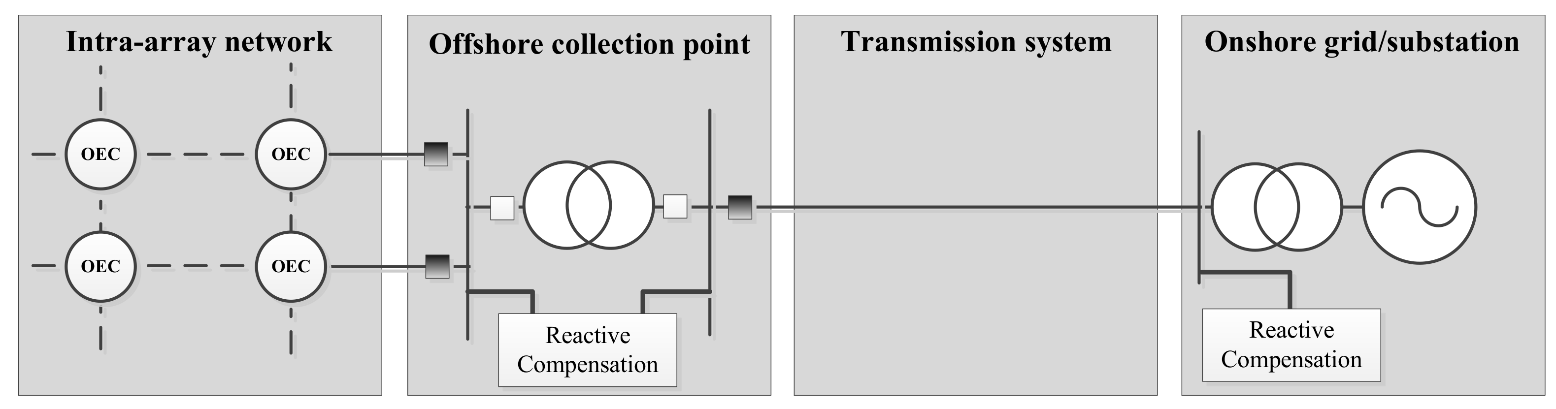
An offshore network can be divided into four main subsystems: the intra-array network, which connects the ocean energy converters (OECs), offshore collection point(s), the transmission system and the point of connection to the onshore network, i.e., the point of common coupling (PCC). A simplified schematic of the subsystems is shown in
Figure 1. The main electrical components within the electrical network can be classified into six categories. These are defined in
Table 1, with components included beside the category headers.
Cables collect and transmit power and communication signals within the array, and connectors allow for a non-permanent connection of different parts of the electrical system. Transformers are used to convert between voltage levels for the purpose of power transmission; they are typically utilised to step-up the voltage at the device level from low-voltage (LV, <1 kV) to medium voltage (MV, 1–35 kV) and also within the offshore collection point to increase the voltage to high voltage (HV, >35 kV) for exporting to shore. They also provide transformation for LV auxiliary supplies and measurement purposes. Switchgear components facilitate the safe installation, operation and maintenance of the array. The power quality component category primarily relates to power electronics-based FACTS devices, but also includes other static equipment used to enhance controllability and power quality.
The development of offshore networks has been led by the offshore wind sector, which has high levels of technological convergence (whereby a given concept, e.g., the horizontal axis turbine, becomes the dominant technology in use) in all areas. Turbine terminal voltage is at 30–36 kV, and the intra-array network is predominantly a radial network configuration. The offshore collection point will be a surface piercing platform with step-up transformers to increase the voltage of the transmission system to 110–220 kV. Such extensive technological convergence is not evident in the MRE sector with many technology concepts competing for market share.
2.1. OEC Device Level
There is some technological convergence of tidal stream technologies and several are entering the phase of extensive sea trials. Horizontal axis turbines are the most mature technology and can be considered to have reached commercialisation. However, despite three quarters of tidal developers focussing on horizontal axis turbines, other technologies, such as ducted turbines and tidal kites, are also receiving considerable attention and are close to demonstrating commercial viability [
3]. Wave technology is slightly further behind, and there is little evidence of technological convergence at the device level. An overview of the possible power take off (PTO) technologies (i.e., mechanisms intended to convert mechanical movement into electrical power) is beyond the scope of this work, but can be found in [
6]. As a result of variations in the PTO, competing wave devices can have significantly different output electrical characteristics, placing different requirements on the supporting electrical architecture.
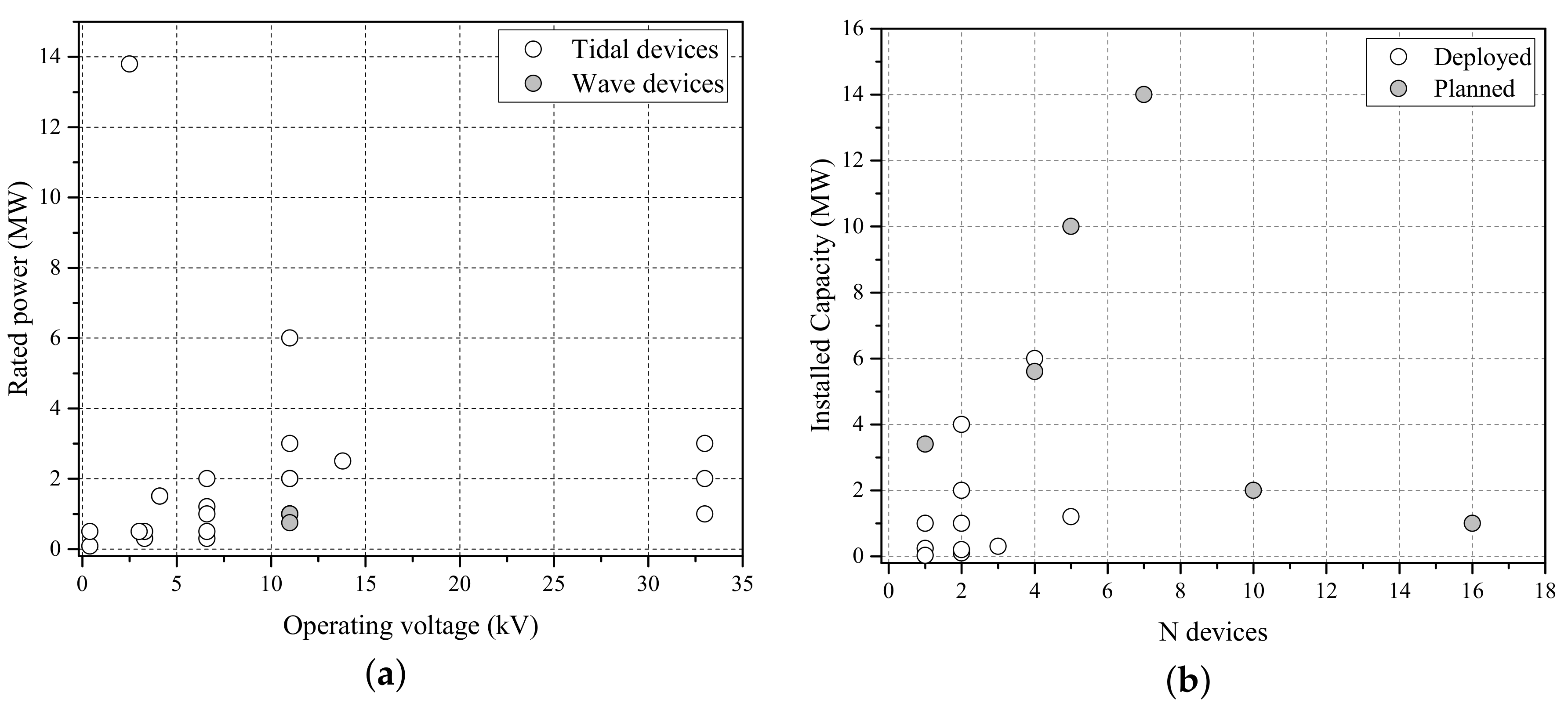
As shown in
Figure 2a, a wide range of output voltages and powers is currently under consideration by device developers. Clustering around 6 and 11 kV is a result of compatibility with test site connections. A thorough review of generators and converters employed in OECs is available at [
7,
8].
2.2. Array Level
Although many wave and tidal energy arrays have been proposed in recent years, few have entered the deployment phase. A number of major studies, including [
9,
10,
11,
12,
13], have investigated likely electrical infrastructures for larger (>30 MW) arrays. A number of solutions are presented: ranging from radial networks to hub and spoke configurations; DC designs, AC designs and hybrid AC-DC designs; onboard converters and transformers, offboard converters and transformers and centralised power conditioning units. However, the conclusions from such studies are often contradictory and can be biased by preference for a given vendor. Furthermore, although arrays of this scale will be required to reduce costs and allow MRE technologies to compete with other forms of electricity generation, the industry is still far from achieving this level of deployment.
Small commercial tidal arrays are beginning to come online and will provide valuable insight for the industry moving forward. In particular, two significant projects (MeyGen [
14] and Bluemull Sound [
15]) are now delivering electricity to the U.K. grid. Both arrays are in construction while also operating and delivering electricity to the grid at partial capacity. The arrays have four and five devices, respectively, each with individual export cables to shore. MeyGen is the largest developed and has consent for a 15-MW connection to the distribution network, while the proposed larger site (398 MW) will connect to the transmission network at 132 kV [
8]. All power conditioning equipment is onshore, with horizontal directional drilling (HDD) utilised to bring each 2-km cable back on shore [
8]. At Bluemull, each 0.8–1-km cable is surface laid and covered by external protection [
16].
Further examples of pre-commercial and demonstration projects are included in
Figure 2b. These are exclusively tidal arrays, as there are no notable array-scale developments of wave energy converters. Although the estimated tidal energy resource is significantly less than the estimated wave energy resource, the predictability of tides presents advantages over other renewable energy technologies [
17,
18], for both network operators and investors. Furthermore, the vast majority of potential tidal sites in the U.K. are located within 10 km from shore in water depths less than 80 m [
19]. Due to the nature of operation some wave devices are suited to deeper water areas, up to 200 m, which can be located up to 50 km offshore [
20]. These more volatile waters present different requirements for device survivability and also require more expensive electrical infrastructure to export power to the shore.
3. Cables
Within the offshore array, submarine cables facilitate the transfer of power from the OEC to the onshore grid. In addition to transferring power, submarine cables serve the crucial role of transmitting communication signals between the array equipment and the shore, which are vital for monitoring and control of electrical components within the network. Cables are classified into two categories: static cables and dynamic cables. This classification is essentially defined by the expected movement of the cable: static cables are typically buried within the seabed, or secured to the surface using external protection, while dynamic cables will operate in the water column.
3.1. Static Cables
3.1.1. Functional Description
Static power cables are used to collect the power generated by the farm through the intra-array electricity network and also to export the generated power from the collection point to the shore. As previously stated, they will also carry communication signals via integrated optical fibres. The purpose of this section is not to present fundamental theory on cable design as several texts, e.g., [
21], deal with this complex subject in great depth.
3.1.2. Current Status
Submarine cables have been around since the 19th century, when they were used to deliver power across small stretches of water. Since then, their use has been driven by the use of interconnectors for grid stability and resource sharing between countries and the extraction of power generated offshore. There are many technological variations in the cable design, but the limitations and applications of different designs is well understood.
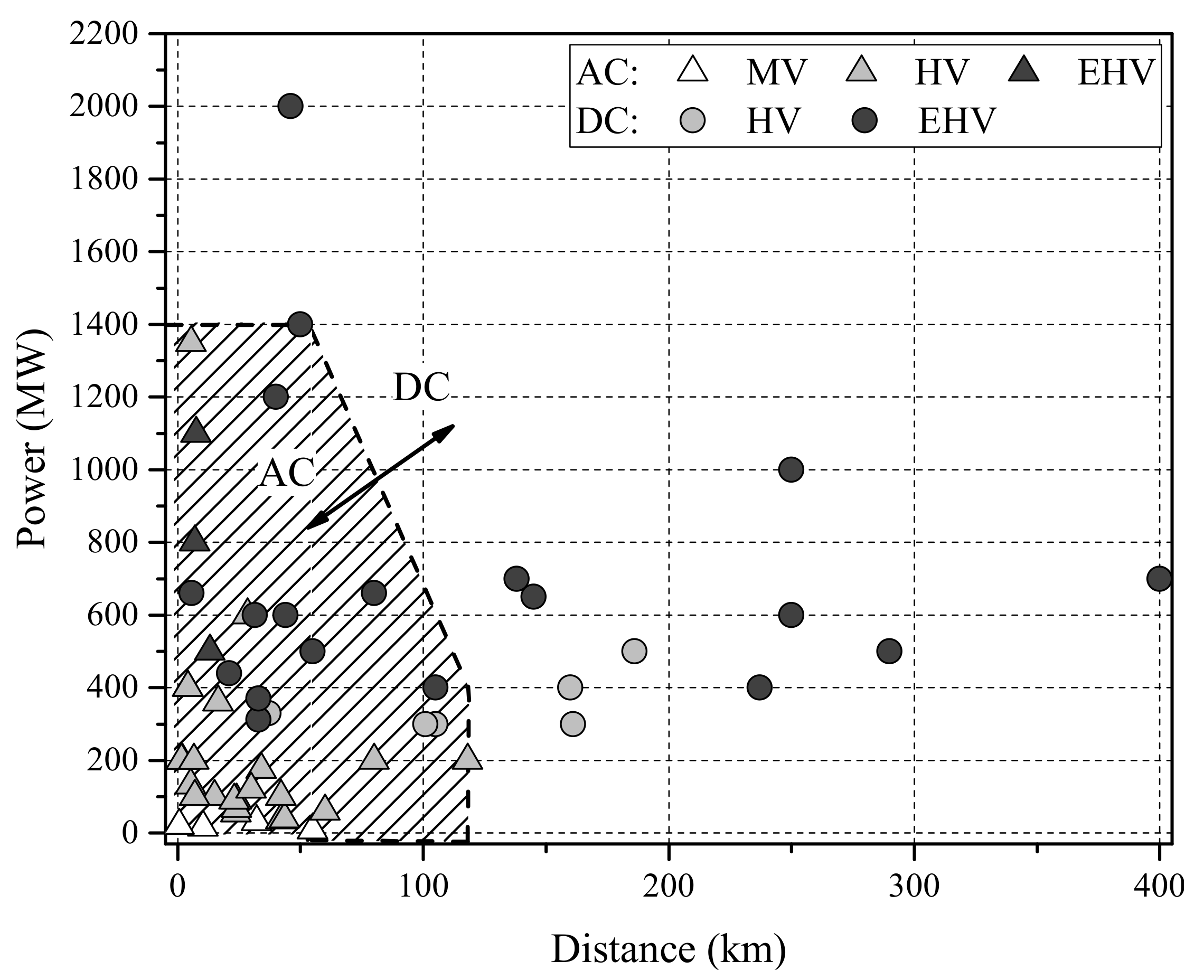
Figure 3 outlines the main technologies employed as a function of cable voltage, current rating and distance for a number of wind farms and interconnectors. All reported wind farm cables utilised copper conductors, with the overwhelming majority using cross-linked polyethylene (XLPE) insulation [
22,
23]. Although 33 kV is the current standard array voltage level, there is some consideration of increasing to 66 kV for offshore wind [
24].
3.1.3. Application in Marine Energy Arrays
The functional capability of static cables far exceeds the current requirements of the MRE industry. However, there are several specific challenges, which result from the high-energy environments, which must be considered. One impact of this is during the installation phase, regarded as one of, if not the most high risk phases of the cable lifetime [
26]. During the installation phase, the cable must support its own weight, and the stress on the cable increases as a function of water depth. Additional forces due to movement of the installation vessel (particularly for smaller cable laying vessels), the catenary support and residual horizontal force on the already laid cable must also be carefully considered to ensure that the manufacturers’ bend radius requirement is adhered to.
Once the cable has been installed, tested and enters the operation phase, the marine environment again has an impact on the cable ampacity, as the current carrying capacity of the cable is influenced by the ability of the surrounding environment to dissipate heat from the cable. Seawater can easily dissipate heat; however, laying the cable directly in seawater would leave the cable susceptible to a number of risks. To minimise these risks, the cable is normally protected, and therefore, the surrounding environment is determined by the cable protection method. A cable risk assessment will consider a number of factors, including: seabed type, seabed mobility, fishing risk and shipping anchors. Comprehensive guides to cable risk assessment procedures are available in [
27,
28,
29].
Cable burial is by far the most common protection method in offshore wind farms (OWFs) and may be stipulated in some regions, e.g., in Germany, the minimum burial depth of OWF export cables is 1.5 m [
27]. A standard burial depth of cables in OWFs is around 1 m, but any value may be agreed between the developer and the supply chain partner; values range from 0.5–3 m [
22,
23]. However, the conditions in MRE environments may make this difficult as they are generally characterised by a rocky seabed, with little sediment for burying the cable. This is evident in the selection of cable protection measures used in the real-world projects described in
Section 2.2. Furthermore, the Sound of Islay demonstration project proposes to surface lay cables and protect with concrete mattresses [
30], while the Wave Hub test and demonstration site utilises rock dumping as an external cable protection [
31].
3.1.4. Cost Data
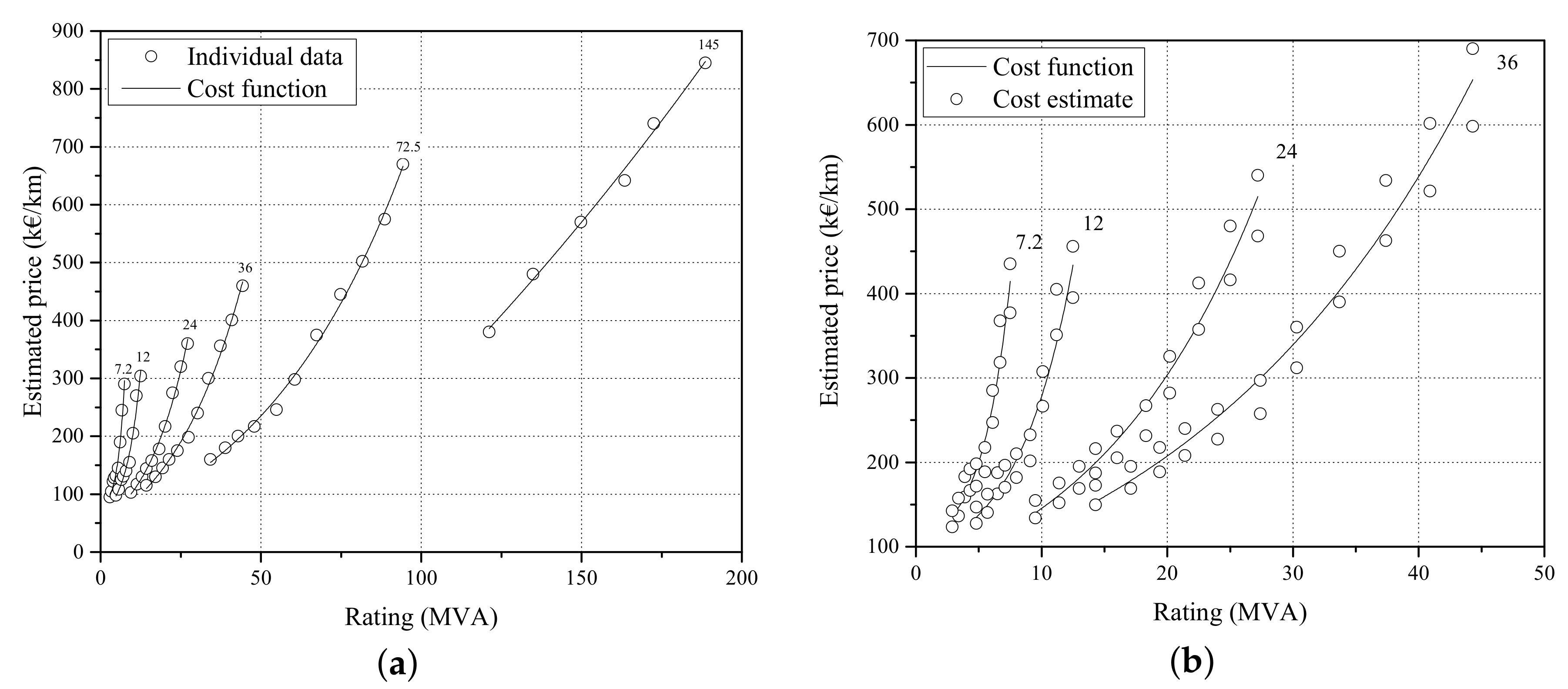
The cost of offshore static cables is given as a unit cost per unit distance. An exponential cost function is defined for offshore static cables [
32] and holds true for data collected during this survey:
where
S is the cable rated power in MVA,
are cost coefficients and
is the offshore static cable cost per unit distance.
3.2. Dynamic Cables
3.2.1. Functional Description
Dynamic cables are used in MRE projects to transfer the power generated by floating OECs to the subsea network and may also be required at the transition to stationary structures (such as fixed tidal turbines or surface piercing substations). The main point of difference with static cables is that double layer armouring is considered standard for dynamic cables in order to provide hydrodynamic stability during installation and operation phases.
3.2.2. Current Status
Dynamic cables are most prevalent in the O&G sector, where they have a number of functions: transferring high and low pressure fluid supply, LV and MV power to pumps and other electrical equipment on the seabed, optical communications, etc. [
33]. To meet these requirements, they normally have steel tubes or thermoplastic hose fluid conduits, optical fibres and LV or MV voltage electric conductors. These cables are designed with high axial tensile and compressive strengths to maximise conductor fatigue resistance during installation and service [
33]. MV power cables with conductor size up to 400 mm
2 have been used [
33]. Their use has been reported in water depths exceeding 1500 m [
34].
Another application area for dynamic cables is the floating offshore wind industry, which has started to deploy its first projects. As opposed to the fixed counterpart, where all the wind farm elements are fixed, thus only static cables are required, the dynamic cables are essential to a floating wind farm as they transport the electrical power produced at the floating platforms, which are designed for water depths >50 m [
35].
Although still in an early development stage, several demonstration prototypes (1–5 MW) have been installed and pre-commercial parks (>5 MW) are expected to be deployed in 2017/2018 [
36]. The demonstration prototypes and pre-commercial parks currently deployed or in construction use free-hanging MV/HV dynamic cables rated from 6–66 kV, with higher export cable voltages (e.g. 110–220 kV) expected to be deployed in commercial wind farms [
35,
37]. Some examples are provided in
Figure 5. To minimize the mechanical loads induced on the cable by the motions and vibrations of the floating platforms, some ancillary elements are commonly used. These are briefly described in
Table 2.
3.2.3. Application in Marine Energy Arrays
Due to the nature of floating OEC power take-off, they will operate in locations with high wave energy densities. The connected dynamic cable will, therefore, be subject to dynamic and cyclical loading regimes, and the cable manufacturer will require precise details of the installation conditions, the sea state conditions for the site and expected dynamic loads of the combined cable-OEC system during operation.
Installation is one of the most critical phases of the dynamic cable lifecycle, with around half of all failures occurring during this phase [
38]. The greatest potential for damage to the dynamic cable will occur during unexpected vessel motions because of adverse weather conditions or when laying needs to be stopped due to an installation equipment failure. This can lead to the cable being in a suspended state for substantial periods, with vessel motions subjecting the cable to continuous bending. However, while these failure modes are relatively well understood, the operational phase of dynamic cables in MRE environment may present a higher risk due to uncertainty in cable-structure interactions.
The forces due to induced motions of the floating OEC may be very different from the forces on dynamic cables used in O&G platforms or even floating wind platforms. While these platforms are designed to remain as stationary as possible and damp all motions, floating OECs are designed to amplify the induced wave motions in order to maximise power extraction. As such, the cable will have to endure greater forces and stresses due to inherent operating environment and induced motions from the OEC itself.
3.2.4. Cost Data
Up to 33 kV, the dynamic cable will be approximately 30–50% more expensive than the equivalent rated static cable. Therefore, the exponential cost function can also be applied for this component (
1). Cost data are given in
Figure 4b, with cost curve coefficients in
Table A2 in
Appendix A. A scale factor of 60–90% more expensive than the equivalent static cable up to 66 kV has also been provided by a major cable manufacturer.
4. Connectors
Connectors allow for a non-permanent connection of different parts of the electrical system, facilitating the recovery of devices and components for maintenance. Connectors are used to connect two cables or a cable to another piece of electrical equipment within marine energy farms. Optical connectors are used to transfer communication signals to pass between the different components in the electrical network. Hybrid connectors include both power and optical contacts. Connectors are classified based on whether they are mated in a dry or wet environment, i.e., above or below the water surface, as dry- and wet-mate connectors. Penetrators, terminators and junction boxes are other connection options available.
4.1. Dry-Mate Connectors
4.1.1. Functional Description
Dry-mate connectors are deployed under water, but they are mated/de-mated in dry atmosphere. During installation of dry-mate connectors, deck area will be required to make the connection, and vessel lift capability must be able to handle both connector ends and cable/component weight during the operation.
4.1.2. Current Status
Dry-mate connectors are not typically found in OWFs, as they are designed such that there is no need to (dis)connect elements of the array, and the turbines are permanent installations, i.e., they are not designed to be recovered to the shore for maintenance. The dimensions of the turbine towers allow for connections within the turbine foundation, which are typically terminated at the turbine switchgear. The collection point, i.e., the offshore substation, has always been a surface piercing platform, and the cables will be directly terminated into the switchgear via the on-deck joint box. However, connectors can be used with floating wind turbines.
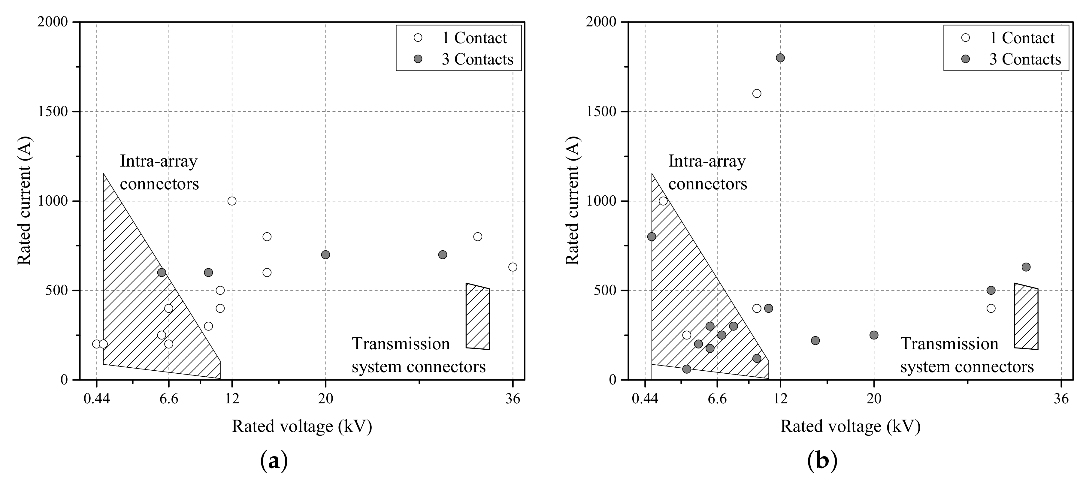
Floating structures can be more readily recovered to shore for maintenance, reducing exposure to risky and costly offshore procedures. In contrast to fixed structures, these turbines will need a non-permanent system of connection, and given that the operating components of a floating turbine are all above the water line, dry-mate connectors are suitable and may be utilised. Although not used in OWFs, dry-mate connectors are an established technology in the O&G sector and have been used in a wide range of applications up to a 3000 m water depth at pressures up to 1000 bar. The connectors used in the O&G sector have traditionally been rated for LV and MV, and there are many examples of low power dry-mate connectors with multiple contacts. Connectors with voltage ratings up to 3 kV, that have from 2–40 contacts, with each contact rated from between 50 A and 100 A, are commercially available and have widely been used [
39,
40,
41,
42].
Figure 6a shows a selection of dry-mate connectors, at the power and voltage levels expected be seen in MRE arrays. Most of these connectors come with a design life of 25–30 years and list a minimum life of 100 mate/de-mate cycles. Furthermore, many of these manufacturers also have a range of hybrid connectors that facilitate connection of optical fibre communication cables along with power cables.
4.1.3. Application in Marine Energy Arrays
Many companies that have traditionally served the O&G sector have also started developing products for the MRE sector. This technology transfer will allow for rapid development of connectors for the MRE sector. The electrical specifications of connectors for the O&G industry, developed at LV and MV, are comparable to the needs of the MRE sector. Indeed, an industry requirement of connectors rated at 0.15–2.0 MW (at 1–11 kV) for the intra-array cable and between 10 and 30 MW at 33 kV for the export cable is proposed in [
43]. Although these technical requirements were issued for wet-mate connector systems, these are equally valid for dry-mate connectors. Advances in floating offshore wind farms will also drive technological development in this operating region.
Specific examples of dry-mate connectors currently utilised in the MRE sector are shown in
Figure 6a. All connectors currently deployed in the MRE sector have three contacts, as this best serves the needs of connecting three core cables. Although not shown in
Figure 6a, one of the highest power rated connectors in the market today is rated at 132 kV and 700 A [
44]. This connector, rated at 160 MVA, has a greater capacity than that required by an MRE array. Similar connectors designed for the O&G sector have operating specifications that far exceed the needs of the marine energy industry. As discussed in
Section 2, MRE farm deployment is expected in water depths up to 200 m. At such depths, hydrostatic pressure and temperature are not expected to be limiting factors, and cost may be reduced up to 50% of the equivalent rated connector used in the O&G sector [
45].
However, the cyclical nature of the environment may accelerate component fatigue. For example, a 3 m tidal range variation in 30 m of water will cause a 0.7 bar pressure variation [
46]. It is important that connectors can withstand the high wave and current loading regimes likely to be encountered, and bend restrictors or stiffeners could be used to limit cable bending at the connector-cable interface. The environment of marine energy sites may also be more conducive to corrosion and marine growth than other sectors, and care should be taken to limit these. The control and mitigation of these will be achieved by maintenance and by selecting appropriate material for the housing. These may be considered as a separate issue to the electrical capability of the component.
4.1.4. Cost Data
It is estimated that dry-mate connectors will cost between 100 and 200 k€ per connector, although no further information of voltage or current ratings is supplied [
47]. However, a major manufacturer of dry-mate connectors suggested that their 30 kV connector would cost approximately 70 k€. A maximum of 15% discount can be expected on the cost of connectors when a large quantity is purchased [
43].
4.2. Wet-Mate Connectors
4.2.1. Functional Description
Wet-mate connectors are both deployed and mated/de-mated under water. They are used to link offshore marine devices to cables and other equipment, which is difficult in the challenging environmental conditions offshore. Wet-mate connectors can be mated/de-mated, depending on environmental conditions, using ROVs, by divers or using stab-plates [
43].
4.2.2. Current Status
Wet-mate connectors, mainly rated at less than 12 kV and without fibre optic connection systems, have extensively been used in the O&G sector [
43]. At higher voltages (>12 kV), there are fewer options. The range of voltage and current ratings of currently available wet-mate connectors is shown in
Figure 6b. Most of these connectors have been pressure compensated for operation at very high pressures, seen at depths of up to 3000 m, as experienced in deep water O&G exploration and production. At such depths, the water temperature is almost constant at 4 °C and does not significantly affect the life and reliability of these connectors. ROV mateable connectors have been the preferred solution at these depths.
4.2.3. Application in Marine Energy Arrays
The emergence of the offshore renewables industry over the past few years has seen most wet-mate connector manufacturers extend their product range to cater to it. Some manufacturers have developed wet-mate connectors that have been designed especially for the renewable application and can be only used up to depths of 100 m.
Figure 6b shows currently available (commercially available, under development and under testing) wet-mate connectors that can be used in the offshore renewables sector. There are plenty of wet-mate connectors available to meet the intra-array network connection requirements of wave and tidal devices currently being tested.
The same cannot be said about wet-mate connectors for the export cable connection. There are only three manufacturers commercially producing/developing 33 kV high power wet-mate connectors. Considering that the export cable connection need not be mated/de-mated as many times as the intra-array network connections, this may be less critical for furthering the advances in the offshore renewables industry.
Offshore marine farms are anticipated to be situated at shallower water depths (up to 200 m) where there would be a higher degree of corrosion and marine growth. These will have to be mitigated through proper material selection and/or by applying coatings [
48]. Even at these shallow water depths, due to the effects of wave and current loadings that the connector will need to endure during installation and operation, these connectors will need to be ROV mateable. Having divers do the mating/de-mating operations will be very sensitive to weather windows and health and safety requirements. Like dry-mate connectors, manufacturers expect wet-mate connector lifetime to be between 20 and 30 years, which is sufficient for marine energy projects [
43]. Furthermore, the rated maximum number of mating/de-mating cycles is between 50 and 150, based on the connection system being used [
43].
4.2.4. Cost Data
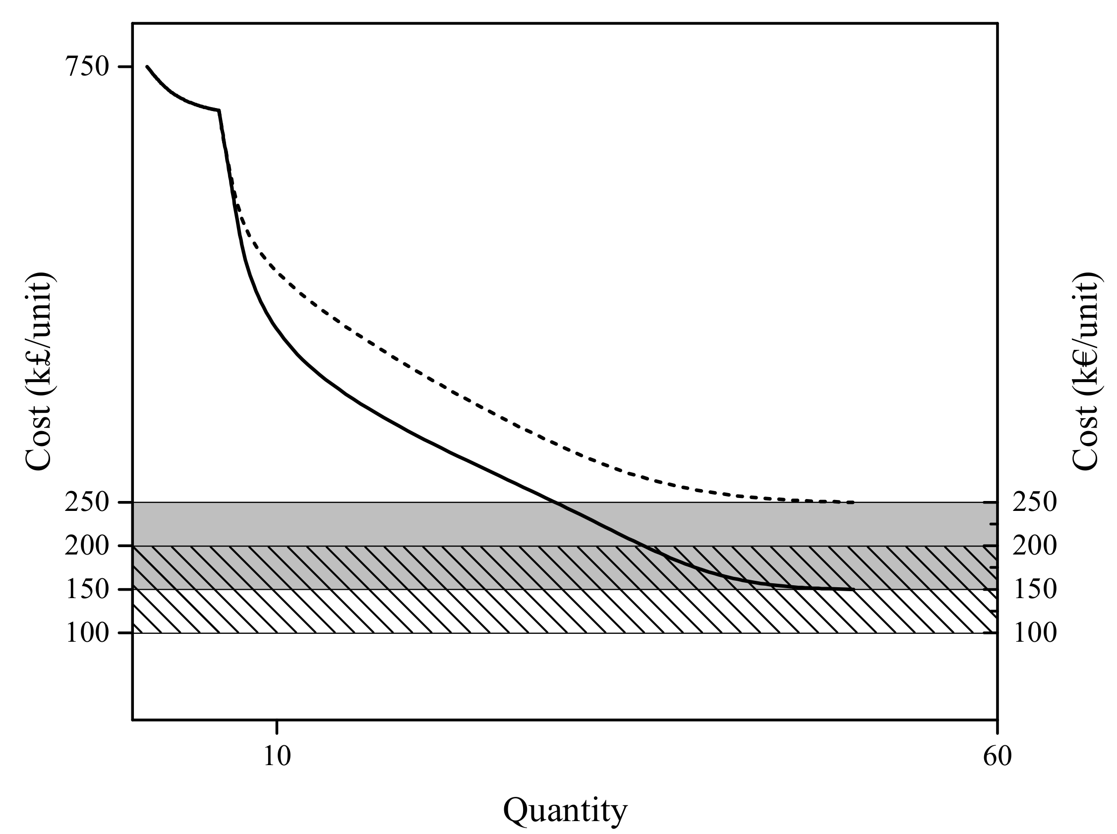
As wet-mate connectors are a relatively new technology in the renewable energy sector, there is limited cost information available. Low-spec connectors may cost as little as 20 k£/unit [
43], but these are not suitable for use in MRE arrays. For the ratings required in MRE arrays, two major manufacturers informed that their wet-mate connectors would be 100 k£ or 2–3-times more expensive than their dry-mate counterparts. As shown in
Figure 7, a major manufacturer estimates a future price of between 100 and 250 k£/unit, accounting for learning rates and economies of scale [
49,
50]. This aligns with other estimates of wet-mate connector cost between 150 and 250 k€ per connector [
47]. However, based on manufacturer data in
Figure 7, it is worth emphasising that this is a projected cost, and the current cost estimate can be up to three to seven-times higher.
4.3. Comparison of Wet- and Dry-Mate Connectors
Connectors will be a key component of the electrical architecture of MRE arrays. They provide fast deployment and recovery of components and can help to reduce installation and O&M costs, which are predicted to be between 33% and 50% of total project costs [
51]. Compared to wet-mate connectors, dry-mate connectors are a more mature technology and are available at higher currents and voltages and lower unit cost [
9]. Accordingly, dry-mate connectors are currently very much the norm for connecting devices. Indeed, one major manufacturer does not consider wet-mate connectors a viable option for array-scale development at this time [
13]. However, MeyGen Phase 1a makes some use of wet-mate connectors, and any operational advantages that are observed during this deployment may help wet-mate connectors become the preferred method of connection in future arrays.
With dry-mate connectors, additional cable length is required on either side of the connector to allow for re-floating operations during mating/de-mating procedures. This extra cable length can be between two- and three-times the sea depth at the location [
9,
43,
52]. Managing such lengths of subsea cable is challenging, especially in deeper or more volatile waters, where concrete mattresses may need to be positioned over the extended lengths of exposed cables to reduce their motion due to tidal currents [
43]. These additional costs, and the increased requirements on installation and O&M vessel specification, must be considered against the higher capital cost of wet-mate connectors.
In practice, many marine energy farm equipment manufacturers and developers envisage a mix of dry and wet-mate connectors within the farm [
11,
12,
43]. There is some consensus that wet-mate connectors will be used in parts of the array where many mating/de-mating operations are expected, i.e., the connection points for the OECs to the subsea network, with dry-mate connectors used for connections to the collection point and the export cables [
11,
12].
5. Transformers
In offshore networks, transformers are used for a large number of functions; the component classification in
Table 1 presents four transformer categories. However, the largest and most expensive are the power transformers used to step-up the voltage to minimise power losses in the transmission back to shore. Accordingly, this paper considers power transformers in most detail and categorises them based on their operating environment. Some additional considerations of transformers in offshore collection points are discussed further in
Section 8.
5.1. Dry-Environment Transformer
5.1.1. Functional Description
Transformers are widely used within onshore and offshore electrical networks. The primary and secondary voltage and rated power will be determined as part of the overall electrical architecture design process. The other main electrical consideration of transformer design is the insulation material. Due to the harmful nature of some insulation materials, this choice is of particular interest in offshore applications, which may be located in environmentally sensitive areas. Based on the type of insulation, each transformer category can be further divided into liquid-filled or dry-type.
5.1.2. Current Status
Traditional liquid-filled transformers use oil as the insulation and cooling medium. Although this is an established method, there are environmental and safety concerns about using this flammable substance. Offshore guidelines suggest that liquid-cooled transformers need to be hermetically sealed and that the cooling medium should not be toxic [
53]; where possible, air-cooled dry-type transformers are the preferred technology [
53,
54]. Furthermore, the Institution of Electrical Engineers (IEE, now the Institution of Engineering and Technology (IET)) offshore regulations explicitly forbid the use of oil-filled transformers, deeming this a potential fire risk [
55,
56].
This is evident in technological trends in the OWF sector, which have used both liquid and dry-type transformers. Historically, dry-type transformers have been prevalent due to their compact dimensions and reduced fire risk. However, liquid filled transformers are more efficient and reliable [
57]. As such, there is significant research into alternative, non-flammable transformer insulating fluids, e.g., [
58]. These have been demonstrated in MV:HV transformers [
59] for the specific application of lightweight offshore substation modules. Wind turbines typically operate between 0.69 and 33 kV. ABB offer a rating of 9.7 MVA at this voltage level, which is to be installed in 8-W offshore wind turbines [
60]. There is also interest to operate wind farms with a 66-kV intra-array voltage level [
24], and turbine transformers are available for this purpose [
61].
5.1.3. Application in Marine Energy Arrays
In the MRE sector, dry-environment transformers will only be required on surface piercing collection points. As such, their application is discussed further in
Section 8.
5.1.4. Cost Data
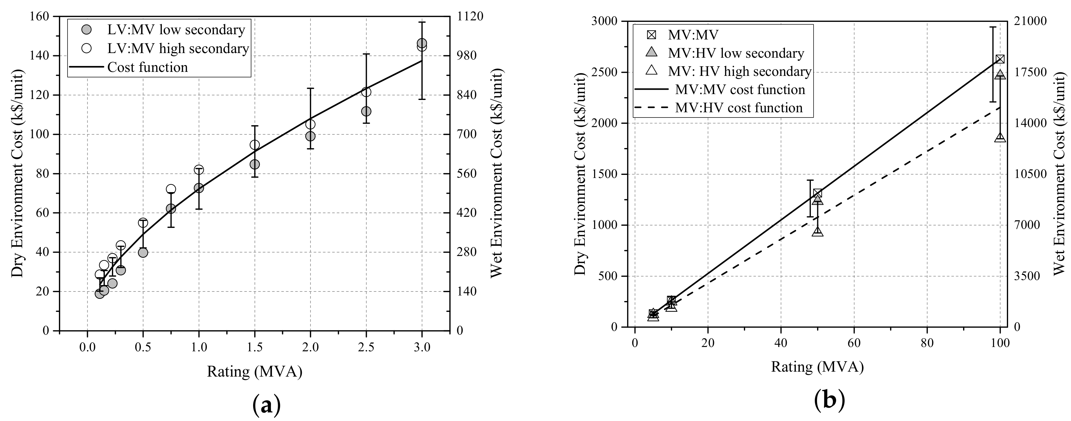
Transformer cost will be determined by the voltage transformation and MVA rating of the unit. A power function, (
2), was proposed in [
32], which holds for data collected in this survey. However, the higher rated voltages have a linear relationship with power. Examples of dry environment transformer unit costs are given in
Figure 8, based on data obtained from [
62]. An oil-type transformer is typically 1.3-times the price of a dry-type transformer [
63].
where
S is rating of the transformer in MVA,
are cost coefficients and
is the transformer unit cost. Coefficients values are given in
Table A3 in
Appendix A.
For the LV:MV transformers shown in
Figure 8a, the transformer with higher rated secondary will be between 40% and 60% more expensive for lower rated powers, although this difference reduces for larger rated units. This is consistent with general advice available in literature, e.g., it is stated that LV: 66 kV wind turbine transformers are about 40–50% more expensive than LV: 33 kV transformers [
24]. Conversely, for the MV:HV transformers shown in
Figure 8b, the transformer with the higher rated secondary will be 25% cheaper.
5.2. Wet-Environment Transformer
5.2.1. Functional Description
The function of the subsea transformer is identical to a standard power transformer, it is only the operating environment that changes. The general development process for a subsea transformer is as follows:
A dry-type topside transformer is designed and developed for a project;
The transformer is placed in a water-tight and liquid-filled container. The liquid is pressure compensated with the outside water pressure to ensure that the system does not collapse when placed under water.
5.2.2. Current Status
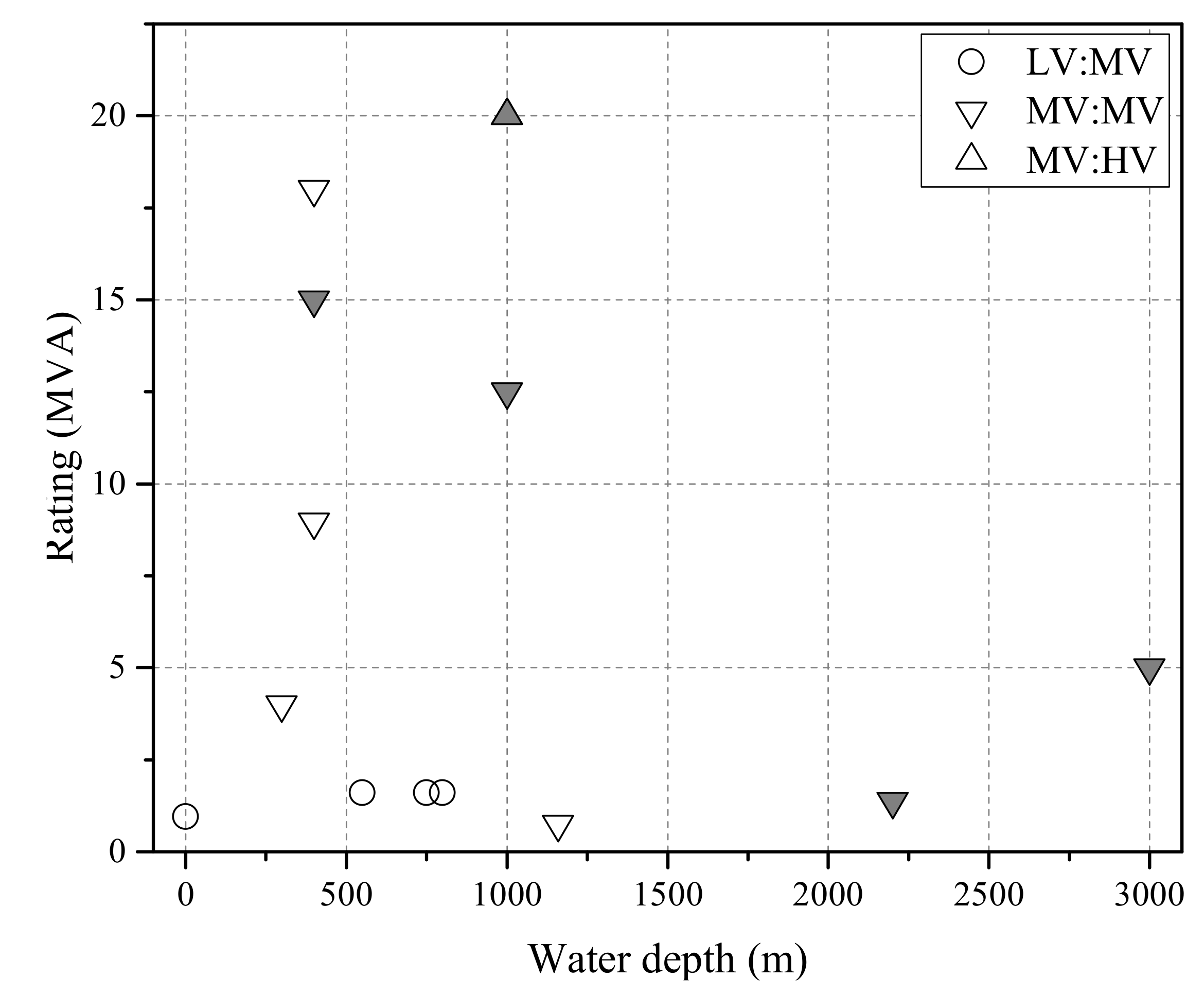
The first subsea transformer, rated at 750 kVA 10.5/3.5 kV, has been in operation since 1998 at a depth of around 1000 m [
64]. This has progressed with two operational subsea transformers, rated at 1.6 MVA 11 kV/1 kV, in operation since 1999 at a depth of 500 m [
65]. Since then, there have been incrementally larger units developed with recent designs ranging from 5–20 MVA [
66] up to 70 MVA [
67]. Some recent designs, rated at 3 MVA, 6.6:22 kV and qualified up to 3000 m, utilise a biodegradable and environmentally friendly cooling liquid instead of oil [
64,
68]. An overview of operational subsea transformers is provided in
Figure 9.
5.2.3. Application in Marine Energy Arrays
One concern of the use of subsea components specific to the MRE sector is the possibility of marine growth on cooling conduits, which may reduce the ability to dissipate heat to the surrounding environment. A typical transformer’s environmental temperature design range can be from
–
°C, with the average 24-h temperature not exceeding 30 °C and the average annual temperature less than 20 °C [
69,
70]. In subsea operation, cooling is provided by natural convection with the seawater, but similar temperature requirements would be considered. Several manufacturers have extensive experience of designing transformers to operate in extreme conditions, including the corrosive salt spray environment encountered offshore. Examples from the MRE sector include the 950 kVA step-up 0.69:11/33 kV transformer in the Pelamis device. One tidal turbine design concept includes a 0.69:6.6 kV transformer in the nacelle [
19].
When operating in this environment, motion must be carefully considered, as vibrations can adversely affect electrical equipment. There are several technical standards that define vibration and shock tests commonly used to design and test equipment in the OWF industry, e.g., IEC 60068 [
71]. Installation conditions will be specified by the manufacturer and should be considered when selecting the vessel to avoid excessive movement.
5.2.4. Cost Data
Based on conversations with major transformer manufacturers, subsea transformers are tailored for each project and thus are not yet commercially available off-the-shelf. Although actual costs for subsea transformers are not readily available, a major manufacturer provided a scale factor of six- to eight-times to convert the cost of dry-type topside transformers into a reasonable approximation of subsea transformer costs.
Accordingly, a power function is again utilised to express the relationship between transformer rating and cost (
2). In
Figure 8, the mean scale factor value, i.e., seven, is shown. The error bars show the upper and lower boundary of six- and eight-times the cost function. Coefficients are given in
Table A3. No other cost data for subsea transformers was identified in the literature.
6. Switchgear
6.1. Functional Description
Switchgear is a general term used in electric power systems that includes switching devices such as electromechanical disconnect switches, circuit breakers (CB) and fuses to isolate, protect and control electrical circuits and equipment. During normal operation, the switchgear can redirect power flow and permit generators to (dis)connect from the power system. Under abnormal conditions, such as during short circuits where high currents are present, the switchgear can detect faulty conditions and disconnect the unhealthy section from the system. They also provide isolation during installation and maintenance activities, playing a critical role in increasing power system reliability, safety and security. Switchgear components are classified by: voltage, current and interrupt rating, insulation type, operating method, application and purpose. By using these classifications, equipment manufactures can design a proper system according to its intended application.
6.2. Current Status
The key component in switchgear are disconnect switches or CBs. LV, low power CBs, used in domestic and commercial applications, operate on thermal or thermal-magnetic principle. However, in MV and HV applications, an arc is produced any time an electrical circuit is interrupted. The arc must be extinguished to ensure current flow is completely depleted. When a short circuit occurs, high currents can flow into a circuit before it is opened by the switchgear. The size and construction of MV and HV CBs are different due to the insulation requirement and arc-extinction process. HV CBs are generally classified further based on the medium used to extinguish the arc, such as vacuum, air-blast and sulphur hexafluoride (SF6).
In HV and high power applications, SF6 gas-filled CBs are very popular and have widely been used for arc-extinction since the 1980s. SF6 is an inert gas with excellent insulating properties. SF6 maintains its thermal and chemical characteristics for a long time, which makes it highly reliable for CB applications. A gas blast applied to the arc must be able to cool it rapidly so that gas temperature between the contacts is reduced from 20,000 K to less than 2000 K in a few hundred microseconds, so that it is able to withstand the transient recovery voltage that is applied across the contacts after current interruption.
Typically, the switchgears utilised in OWFs are gas-insulated. Several manufacturers provide self-contained solutions for offshore wind applications, with an emphasis on compact and modular structures for easy installation within turbine foundations [
72,
73,
74]. Switchgears with voltage rating, current rating and breaking capacity of 40.5 kV, 2.0 kA and 31.5 kA respectively have been realised for installation in turbines (for example in the Greater Gabbard offshore wind farm, U.K. [
75]). Switchgears housed on fixed platform substations with voltage rating, current rating and breaking capacity of 245 kV, 4 kA and 50 kA respectively have been realised (for example at the Gemini offshore wind farm, Belgium [
76,
77]). Switchgears rated up to 550 kV, 5 kA and 63 kA are commercially available [
74].
The OWF industry and O&G exploration facilities are paying more attention to under-water switchgear systems closer to the subsea load center, as it reduces operational expenditure and the cost of power lines. Consequently, various fault current limiting technologies have also been studied in the literature for subsea switchgear systems [
78]. Recent advances in seabed installations provide efficient and economical subsea-to-beach solution for challenging environments like deep-sea and the Arctic, which also eliminates the need for floating production units. Subsea switchgear components have similar operating principles and characteristics except that they are housed inside high pressure withstanding containers suitable for under-water (e.g., at the seabed depth of 1000–3000-m) operation for a long time (e.g., >30 years) [
79,
80].
The current technology used in subsea applications is mostly a magnetically-actuated vacuum quenched switch or a CB chamber filled with SF6 gas. The CB typically consists of capacitors that provide momentary power during outage conditions, control modules with sensors to detect faults and provide appropriate signals for proper operation, etc., supervisory control and data acquisition (SCADA) systems are typically employed for remote system control. This is especially important for subsea applications. In recognition of the importance of this emerging market, the IEEE standards association is actively developing the Subsea Electrical Power Standardisation (SEPS) under the base standard code IEEE 67886.
6.3. Application in Marine Energy Arrays
Essentially, the role of the switchgear within a marine energy array will be similar to the role of the switchgear in offshore wind farms. Considering that the power ratings of OEC farms in the near to medium term would be much smaller than offshore wind farms, the availability of a switchgear of appropriate ratings will not be an issue for OEC farms, as exemplified by the examples given earlier in the preceding section. However, differences may exist in protection coordination schemes, which are well established for OWFs. Generally, these are divided into protection zones, which reflect the radial network structure: generator, feeder, busbar, transmission transformer. Selectivity is important to ensure that only faulted parts of the network are tripped, isolating the minimum area required for safe operation. At the time of writing, as it is unclear how MRE arrays will be formed, it is hard to predict protection coordination schemes. In the Wave Hub and EMEC demonstration sites, all switchgear are located onshore.
6.4. Cost Data
Previous research has identified a linear linear relationship between switchgear cost and voltage rating (
3) [
32]. Cost coefficients are given in
Table A4.
where
V is rated phase voltage in
V,
are cost coefficients and
is the switchgear unit cost.
7. Power Quality
Prior to the connection to the wider onshore electrical network, offshore energy arrays will have to demonstrate grid code compliance. Grid codes are designed to support connection and use of electricity networks, whilst simultaneously ensuring quality and security of supply. Flexible AC transmission system (FACTS) devices are of particular interest in the context of grid integration of large offshore energy arrays as they can help to ensure grid code compliance.
7.1. Functional Description
There are a number of different devices which can be applied, and this is project specific. However, the static VAR compensator (SVC) and the static synchronous compensator (STATCOM) are the most widely-utilised FACTS devices today. Series-connected FACTS devices such as the static synchronous series compensator (SSSC) could theoretically have beneficial application, as well; however, they are of less interest than the shunt connected devices identified above. This is because the services offered by series connected devices make them better suited to deployment on the wider transmission network rather than on the generation side. This is in contrast to shunt-connected devices, which are well suited for use at load and generation buses such as the PCC of wind plants. The high cost of series connected devices like the SSSC also makes it hard to justify their use in many cases.
Both SVCs and STATCOMs are shunt connected devices capable of absorbing and generating reactive power. The SVC is typically made up of a thyristor switched capacitance (TSC) in parallel with a thyristor switched reactance (TSR) or thyristor controlled reactance. A STATCOM consists of a self-commutating inverter with a capacitor on the DC side. The inverter is usually built using insulated gate bipolar transistors (IGBTs) that can be switched on and off in a controlled fashion. As a result, the STATCOM has a faster response and wider bandwidth than the SVC. The maximum reactive current injection of the STATCOM is also independent of the terminal voltage. This leads to better voltage support and improved transient stability margins. This means that the STATCOM is more effective than the SVC for improving low-voltage ride-through. Despite the superior characteristics of the STATCOM, SVCs provide a lower cost solution and may, therefore, be favoured in certain applications.
In certain cases, static compensation units may be used in combination with the dynamic compensation offered by FACTS devices. The static compensation, which usually consists of mechanically-switched capacitors and reactors, is good for second to minute responses and is used to shift the dynamic reactive capability towards a lagging or leading value as required. Switched reactors can be used to compensate for the cable capacitance, and such static compensation can significantly reduce the requirement from dynamic compensation units, which are usually costlier.
7.2. Current Status
The functionality and benefits offered by FACTS devices like the SVC and STACOM are well understood by the power system community, and they have been widely used in the wind sector to ensure compliance with stringent grid code requirements. A number of solutions is available from major manufacturers. To date, SVC and STATCOM devices have mainly been used to perform the following functions in the wind industry:
Reactive power support
Providing fault ride-though (FRT) capability
Voltage control at PCC
Power quality control (Flicker, Harmonics, power factor correction)
Some application examples from OWFs are included in
Table 3.
7.3. Application in Marine Energy Arrays
As array sizes grow and marine energy farms connect into the higher voltage sub-transmission and transmission networks, grid code requirements will become more stringent. It is unlikely that these farms will be able to connect to the grid and comply with the relevant grid codes. FACTS devices will be called upon to perform many of the same functions as those already being performed in the wind industry.
Due to the nature of shunt connected FACTS devices and the functions they perform, it is desirable to connect them at or as close as possible to the PCC, i.e., they are always onshore and usually in the onshore substation. Therefore, it is unlikely that any adaptations related to locating the devices offshore will be necessary. As a result, these same devices could easily be applied in MRE arrays.
Combining devices with energy storage is a development that would improve capability. Some manufacturers already offer such products. The ability to provide active, as well as reactive power support may make such devices more appealing to electric service providers [
86]. This could be particularly useful in the context of ocean energy farms because many of these farms are likely to be connected to the lower voltage sub-transmission and distribution networks where the ratios of line reactance to resistance (X/R ratio) are much lower (typically less than 0.5 [
87]). In these situations, the deviations in voltage due to unit changes in reactive power are small. This means reactive power control for voltage regulation is less effective and not very efficient. As a result, it may be necessary to curtail active power output at certain times or to restrict the amount of generation that can be connected to these networks to ensure that voltage limits are not violated. The use of energy storage, in combination with a FACTS device such as the STATCOM, could alleviate the need to curtail generation and allow more generation to be connected without carrying out expensive network upgrades. This could have wide reaching financial implications as it could reduce the cost of obtaining a grid connection and increase revenue once the farm is connected.
Adding energy storage to a STATCOM can also significantly improve the oscillation damping [
86]. With no energy storage, the STATCOM takes two seconds to achieve constant voltage, whereas the STATCOM plus energy storage is able to achieve constant voltage within 0.5 s. A large OEC farm may also introduce an unacceptable level of flicker into the local power system. Installing a combined FACTS device with energy storage near the OEC farm is one solution to resolve flicker [
88]. The most stringent limits for flicker require an energy storage time constant of three seconds [
89]. The STATCOM plus energy storage is able to exceed this requirement, and its performance is superior to the STATCOM alone [
86].
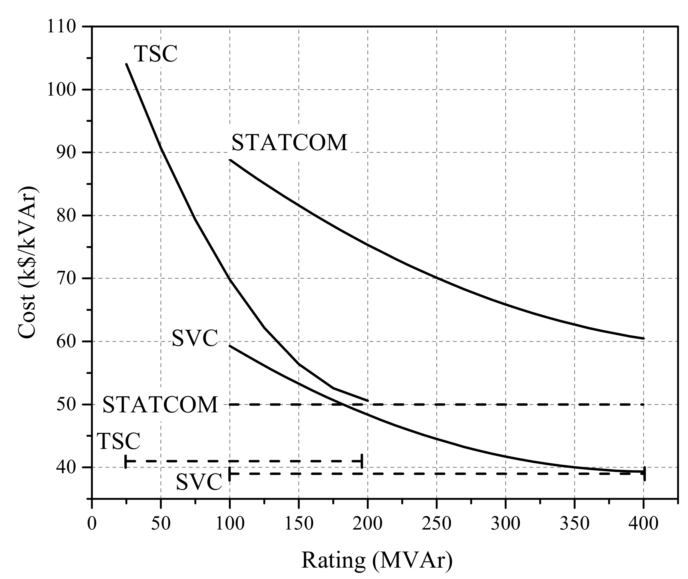
7.4. Cost Data
Some guidance is available in literature on FACTS costs, with raw component costs taken from [
90,
91]. The cost can be represented by a second order polynomial (
4). Coefficients are given in
Table A5, with values presented in
Figure 10.
where
Q is the rated reactive power in MVAr,
are cost coefficients and
is the component unit cost.
8. Collection Points
Offshore collection points are used to support the transmission of power generated offshore to the onshore grid connection. The functional requirement of the offshore collection point is determined by the project specification; particularly, the OEC operating voltage, the length of the transmission cable and the installed capacity of the array.
8.1. Functional Description
The purpose of the offshore collection point is to collect the power from the intra-array cables from a number of devices or clusters of devices and then transmit the power to shore, possibly at a higher voltage level. This design concept is required as the distance to shore and installed capacity of the farm increase. As illustrated in
Figure 1, the main components that may be present within a traditional offshore collection point subsystem are: transformer, switchgear and reactive compensation, which have been introduced in previous sections. There are many possible variations of this approach, which are defined by the use of different combinations of these components and the operating environment.
8.2. Current Status
A number of different solutions can be found in the offshore wind sector and O&G industry. In OWFs, an offshore, fixed platform substation design is prevalent. Although the main purpose of the offshore substation is to transform to higher voltage for transmission to shore, there are several other important features that are commonly included in the design, e.g., switching functionality to connect/disconnect equipment and house protection equipment, monitoring/SCADA devices, harmonic filters and reactive compensation to ensure safe operation of the array and achieve grid code compliance.
The variations between offshore platforms are relatively subtle and will tend to be a result of transformer selection. The main design choices to be made are the selection of export voltage level and the number and winding configuration of the transformers. Export voltage in OWFs is typically between 110 and 220 kV. For installed capacities of less than 100 MW, two-winding transformers are commonly used [
92]; with three-winding transformers employed in larger installations [
93,
94]. Although the number of transformers will be at the discretion of the developer, this may be governed by design guidelines, e.g., U.K. grid codes stipulate that all offshore power park modules (i.e., a group of intermittent renewable generators) with installed capacity greater than 90 MW should be able to supply up to 50% of the installed capacity for an N-1 contingency event [
95]. A cost-benefit analysis study of transmission options for offshore wind farms observed that solutions with two substation transformers was more economical for farm sizes greater than 120 MW [
93].
Incorporating one or two transformers on a single offshore platform results in large dimensioned top-side structures, which require substantial foundations. Weights of modern offshore substations range between several hundred to several thousand tonnes. The significant civil works and offshore logistics operations associated with such developments require vast amounts of time and capital, and there is interest in the offshore wind community to consider alternative solutions. Incorporating smaller and lighter designs will allow installation by the foundation/turbine installation vessels. It is even possible to integrate the transmission transformer with a turbine foundation [
59]. Other novel solutions include the floating substations being developed as part of floating offshore wind farms [
96]. Offshore platforms are also widely used in the O&G sector, but with additional components required to drill, extract, process and store (as necessary) oil or natural gas. As a result, these structures are much larger than the platforms used in renewable energy arrays. However, in deep water applications, subsea infrastructure can be utilised, and the O&G industry was first in developing underwater solutions to supply power to pumps and compressors up to a 3000 m water depth [
66,
80,
97].
8.3. Application in Marine Energy Arrays
The necessity of using fixed, or floating platforms, in OWFs is driven by the long transmission distances and large power transfers. As such, the technologies and design rules applied within the offshore wind industry may not be directly transferable to MRE projects. For example, it is often stated that there is no need for an offshore substation when transmitting less than 100 MW over a distance less than 15 km at 33 kV [
47]. Although commercial scale arrays of this power are not yet on the horizon for MRE projects, the rated voltage of OECs and transmission distance can lie outside these boundaries, and unique, cost-effective solutions must be found. The environmental and visual impact of large platforms close to the shore can also be considered prohibitive to their use in MRE arrays.
Furthermore, the vast majority of OECs have a single connection and cannot naturally form the radial connections, which are predominant in OWFs. In OWFs, ring main units located in the tower are used to daisy chain the turbines together to form radial strings; cables loop in and out of the turbine tower and terminate directly onto a switch. The need to recover OEC devices for maintenance or repair would require two connectors per device to loop the cables in and out. The space required for two connectors would constrain OEC design, and the cost of such a connection system may be prohibitive.
For small, near-shore installations, this is not a big issue as the power generated in the OEC can be transmitted directly from the offshore area to the PCC. It is feasible to have one export cable per device, without utilising an offshore collection point. This is the approach applied for the initial development at MeyGen and is considered an important part of the learning process. However, for larger scale arrays, a large number of export cables is not practically or financially viable. An alternative to the direct connection design concept is to use offshore collection hubs, and it is expected that this technology will be a key enabling technology in the MRE sector. Accordingly, this is one of greatest design challenges for the MRE supply chain, and design flair and novel approaches are required. The Wave Hub collection device is an example of this design concept in operation in the MRE environment [
31]. The Wave Hub is a free-flooding, subsea, carbon-steel structure and has terminations for power and fibre optic cables for four devices, with dry-mate connectors used to serve the dynamic cables. There is no additional offshore electrical equipment, with the switchgear located onshore. In comparison with the direct connection design concept, there is a cost savings from reducing the number of export cables. However, this will lower the redundancy at an array level, as the power output is susceptible to a single point of failure.
More than one offshore collection hub may be present, depending on the intra-array configuration. This can provide greater protection selectivity, i.e., reducing the number of devices which are disconnected by a fault or maintenance action. By introducing additional hubs, it is possible to form star or ‘hub and spoke’ networks for larger-scale arrays and these are commonly proposed as a means of connecting OEC devices in large arrays. Some collection point designs, which house converters, switchgears, transformers and different combinations of these components, are effectively subsea substations. Housing these components in (a number of) centralised hubs may provide a cost-effective solution compared to housing power conditioning equipment at each OEC. Such designs have similarities to the seabed process control hubs used to control electrical and hydraulic equipment in the O&G industry. Although the O&G sector has led the way in subsea transformer and switchgear development, novel solutions are in development for MRE, with subsea substation design concepts reviewed in [
98]. Unlike the solutions common in the O&G sector, these subsea collection points will typically house all components within one single structure for ease of installation; the structure may be a self-contained, pressure compensated, hermetically-sealed unit [
99,
100] or may feature several traditional subsea components fixed to a single support structure [
11]. On-bottom stability will depend on the seabed type; with solutions ranging from suction piles for soft areas to concrete foundations, gravity-based structures or mud mats for hard seabed areas.
Due to the dimensions of the MV components likely to be used, these subsea collection points will be substantial pieces of equipment, and space limitations may limit the number that may be placed within an MRE array. An alternative is to utilise T-off connectors, allowing OECs to form the string topology commonly used for connecting offshore wind turbines. T-off connectors are essentially sockets consisting of three connectors; one to connect the OEC and two to form a radial chain with T-off connectors of the neighbouring OECs or to the collection point or export cable. Such a system would enable devices to have a single connector, making deployment and recovery easier; offering a cost-effective solution for the MRE industry. The authors are aware of at least two manufacturer offering off-the-shelf products developed specifically for OEC devices that can create T-off connections [
101,
102]. Other manufacturers have conceptual designs based on existing industrial standard components. However, these have yet to be developed. Examples from literature of all collection point design concepts are included in
Table 4.
8.4. Cost Data
Collection point cost data are summarised in
Table 5. As subsea hubs and T-off connectors are emerging technologies, there is very little information available on their cost. Only [
9] provides a cost estimate for a T-off connector.
9. Electrical Component Database
The data collected during this review are made freely available for use by the community in a database, housed online at [
5]. The database has been developed as part of an open source tool that provides an integrated platform for the lifecycle assessment of ocean energy arrays with respect to economic, reliability and environmental performance indicators. Further information of the tool is available at [
106].
As such, the database contains additional parameters, which are beyond the scope of techno-economic review presented in this paper, but which are important when selecting components for an offshore ocean energy array. For all components, this includes:
Electrical parameters: standard electrical engineering parameters, such as voltage and current ratings, which provide the basic information required to correctly select a component for a high level electrical design;
Mechanical parameters: which describe the physical attributes of the electrical component, such as weight and dimensions, and those which define the interaction with the environment during installation and operation phases, such as operating temperature;
Cost parameter: the component unit cost, which is required for economic analysis;
Reliability parameters: the component mean time to failure, which is required for reliability analysis.
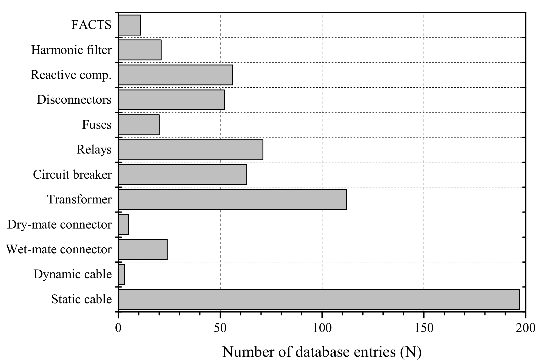
Further details of all electrical and mechanical parameter fields included in the database are given in
Table 6, with the number of database entries for each component type shown in
Figure 11. As component lead times play an important role in installation and O&M planning, these are included in
Table A6 for completeness.
10. Conclusions
Electrical components form a key part of an offshore energy array, transmitting the generated power back to shore and facilitating communication with devices and control elements. The electrical infrastructure may form a considerable portion of the project cost, e.g., it is estimated to account for up to 25 % of offshore wind farm capital cost [
107], and standardised electrical infrastructure is one of the key drivers in commercialising MRE arrays. As such, understanding the main electrical components, their current capabilities and how they can be deployed in MRE arrays is crucial as the industry aims to progress from single-device demonstration projects to array-scale developments.
To this end, this paper presents an overview of a data collection, which focuses on the needs of the MRE sector. The application of the electrical components within MRE arrays is discussed, and cost data are presented. This consolidates existing literature, providing updated cost information on static cables and guidance on costing dynamic cables and subsea transformers. Additional parameters, which include the main electrical and mechanical parameters, are available in an online database. This ensures that the data collection is compatible not only with load flow analysis and electrical design, but also for assessing logistic phases, i.e., vessel and weather window requirements, which is of particular importance when installing in highly dynamic offshore conditions. This is also important as the capital cost of components should not be considered in isolation, but should ideally be assessed with consideration of the installation, operation and maintenance cost. The open source repository and lifecycle analysis tool are available at [
5].

 ,
, 


