Fault Ride-through Capability Enhancement of Voltage Source Converter-High Voltage Direct Current Systems with Bridge Type Fault Current Limiters


Abstract
:1. Introduction
- ▪
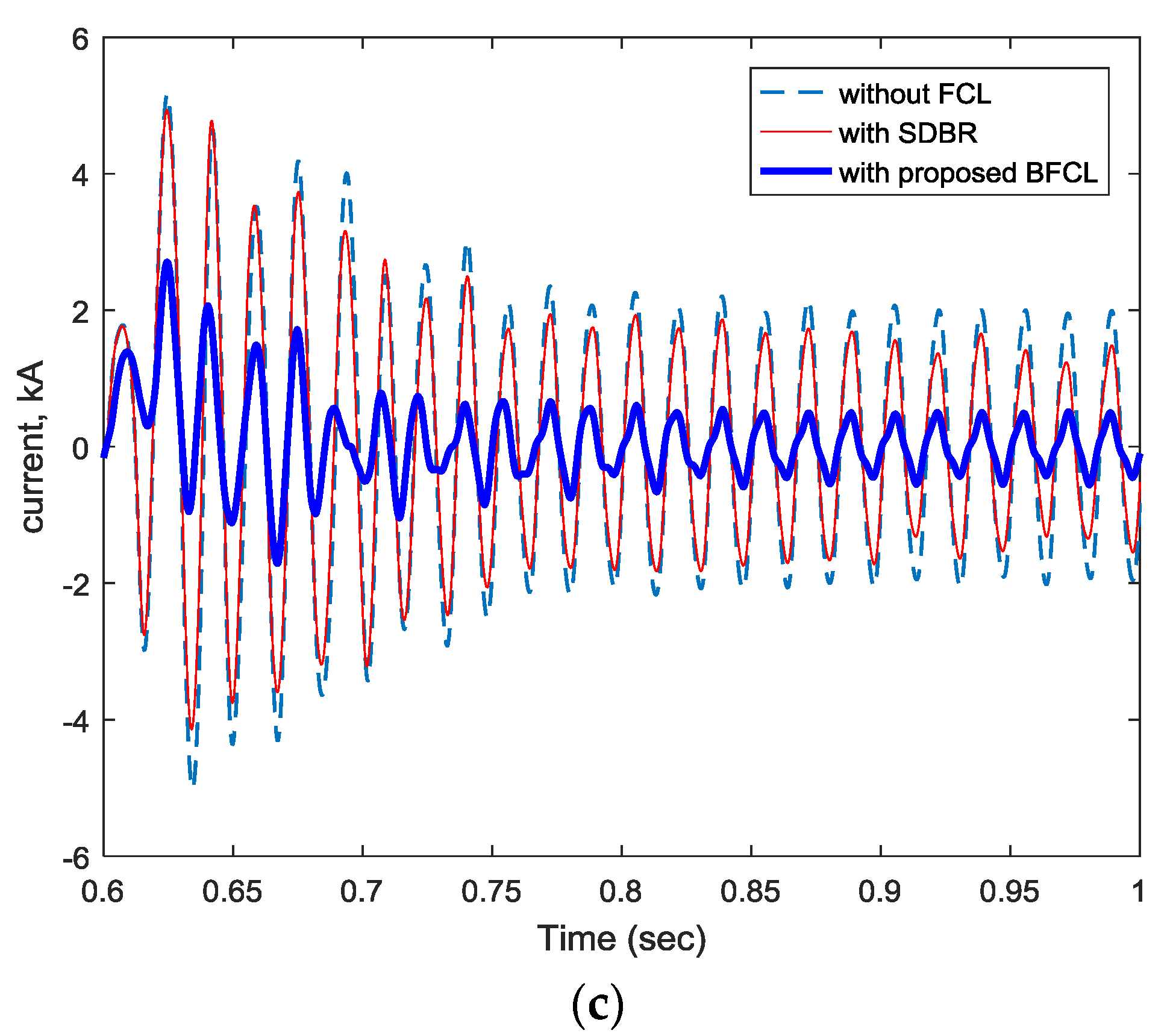
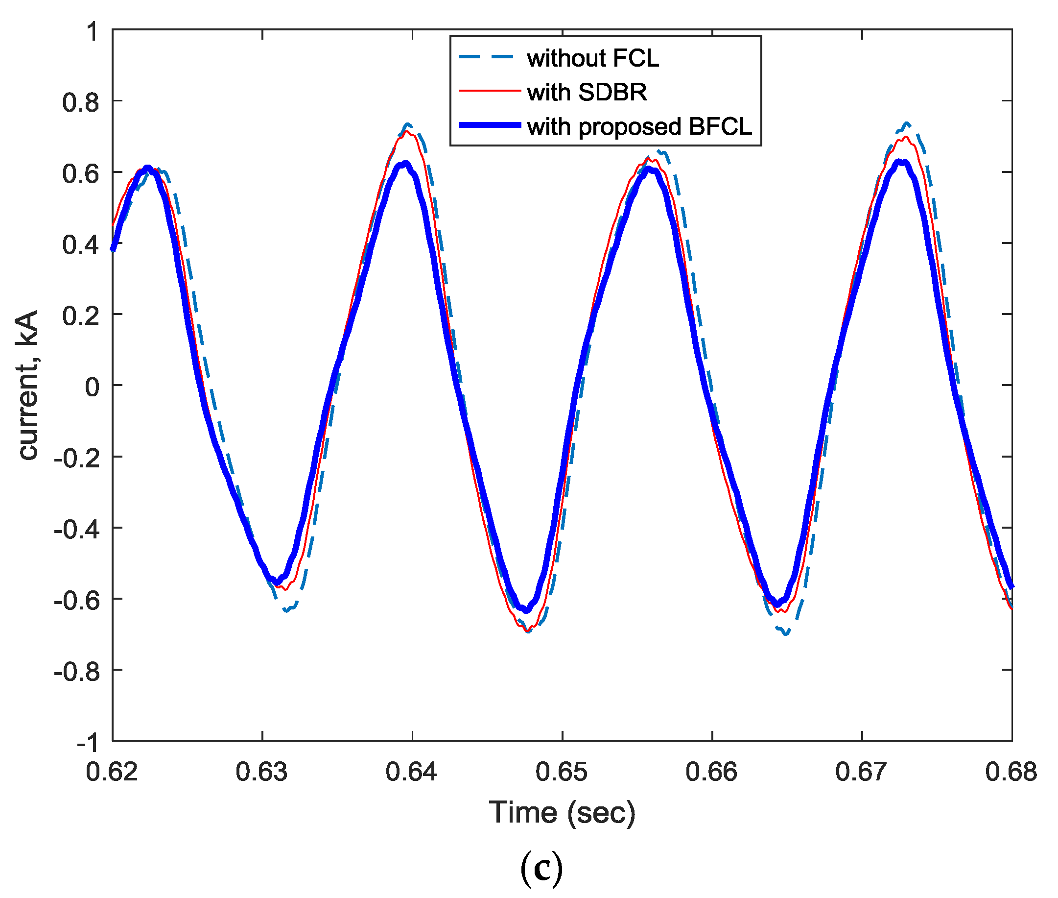
- The proposed BFCL solution is able to limit fault currents of VSC-HVDC system for both symmetrical and unsymmetrical faults.
- ▪
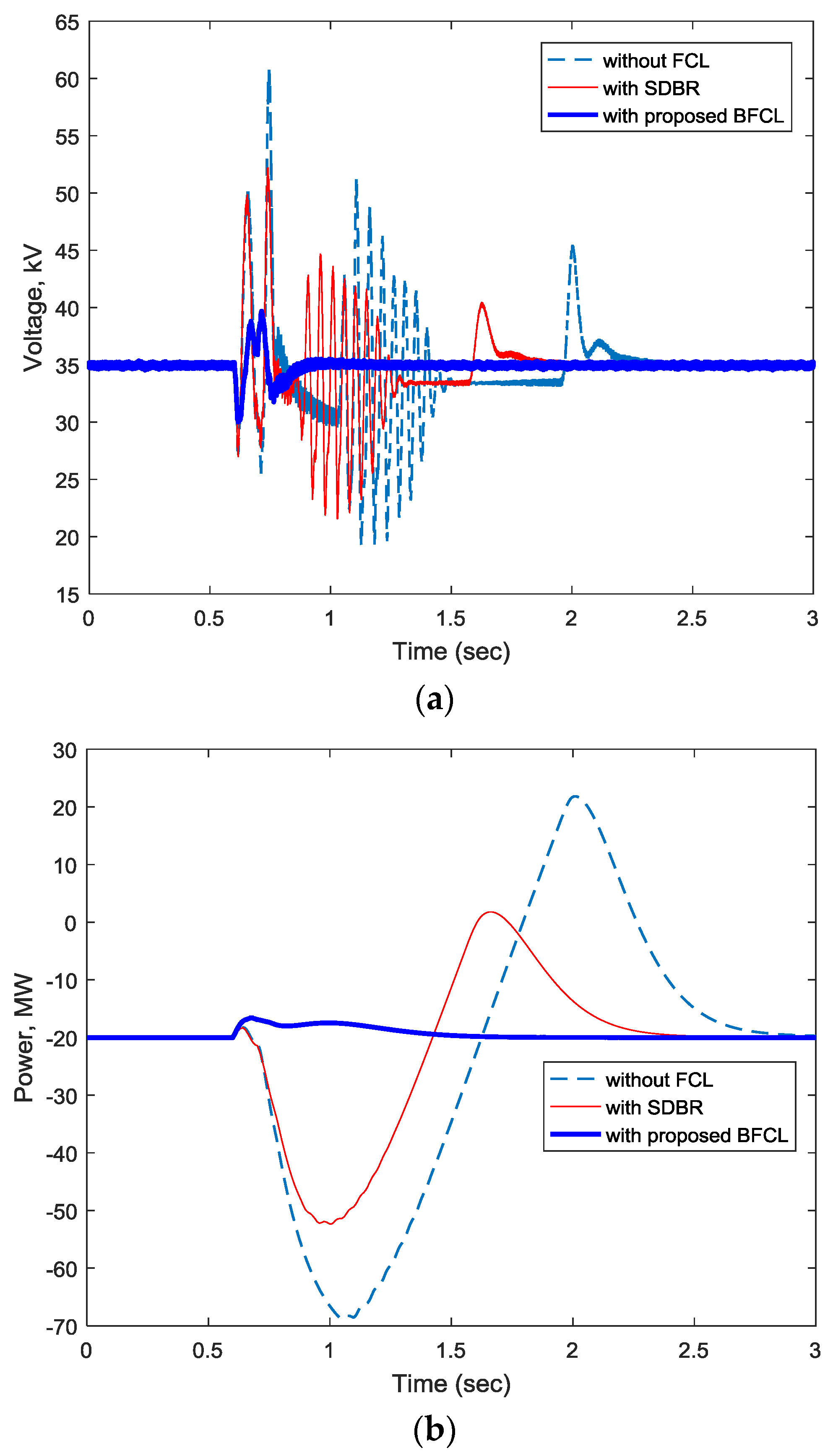
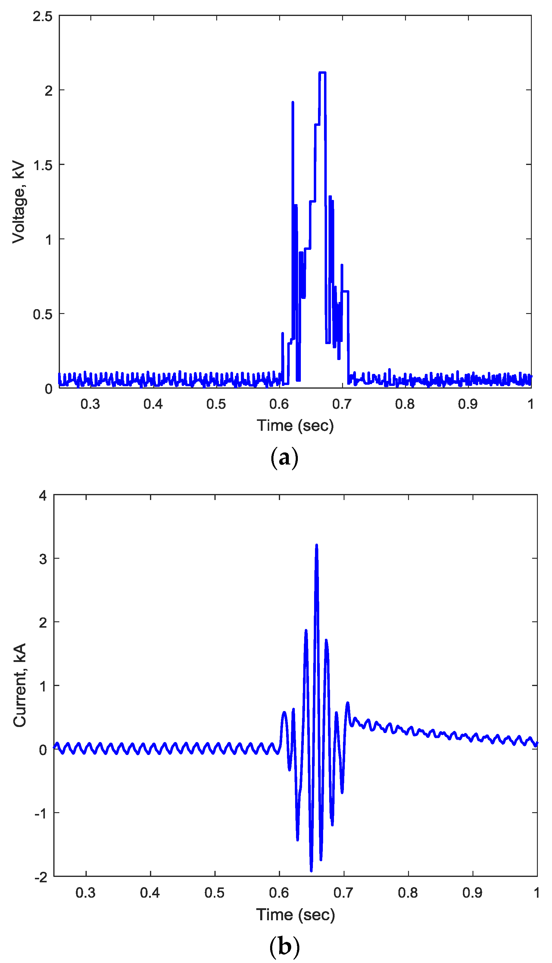
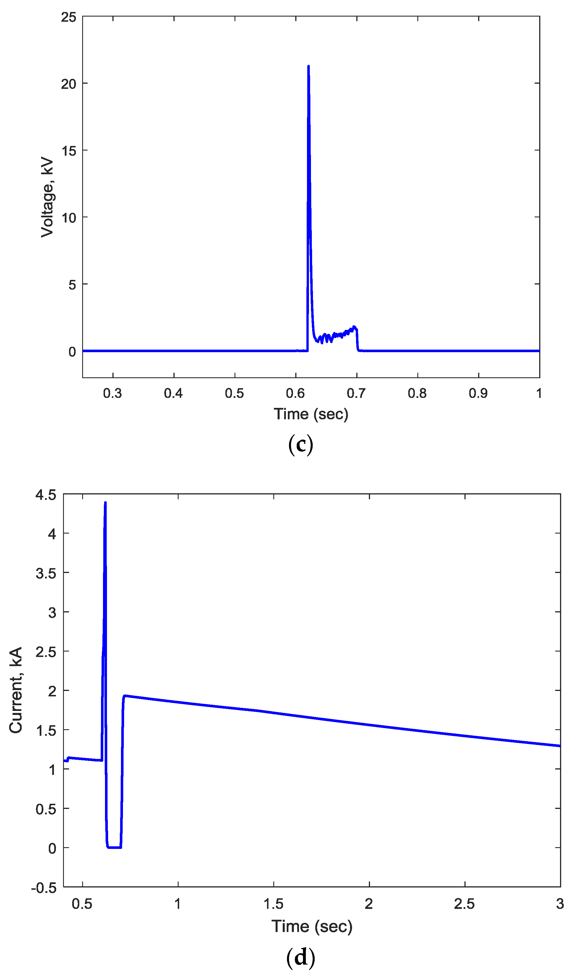
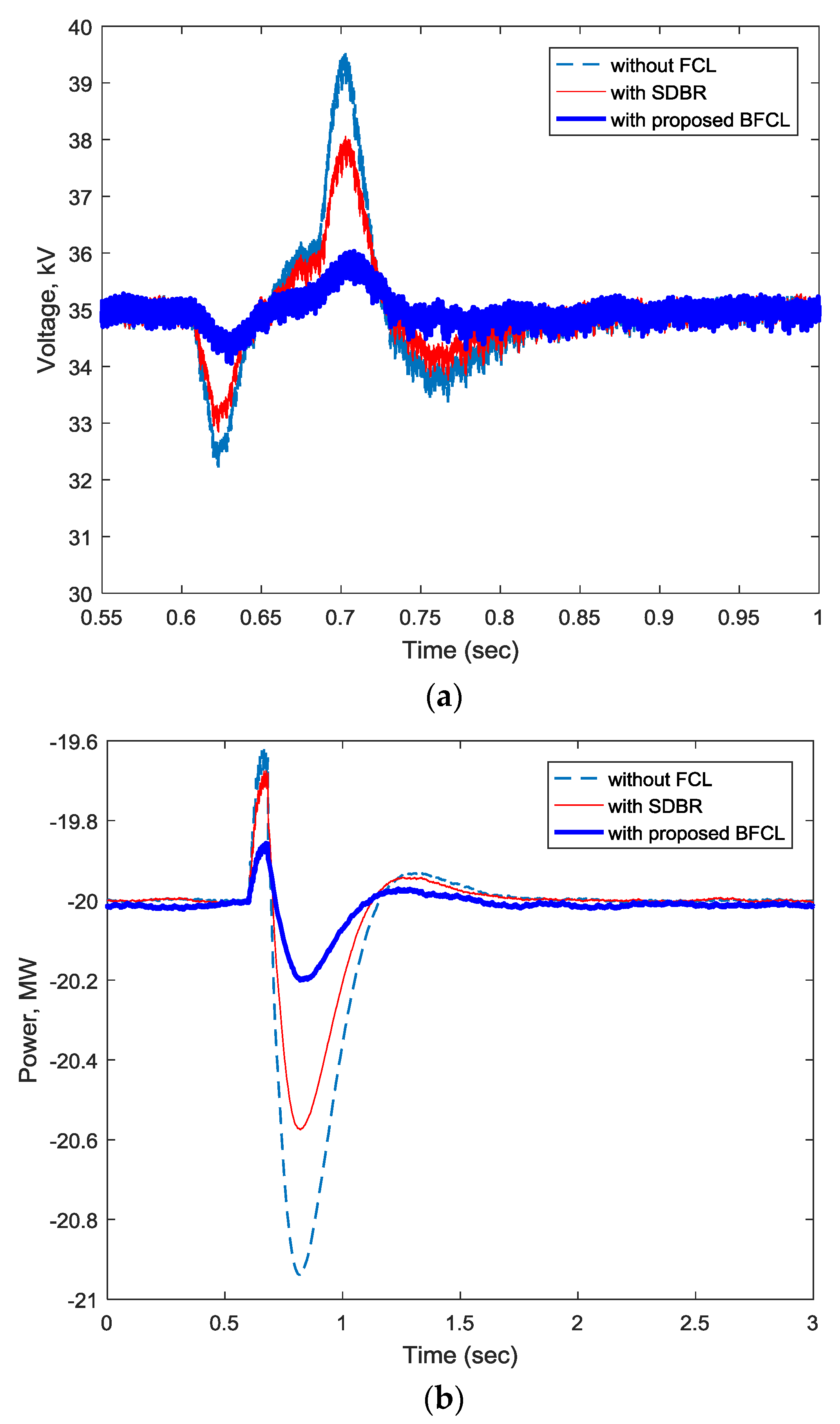
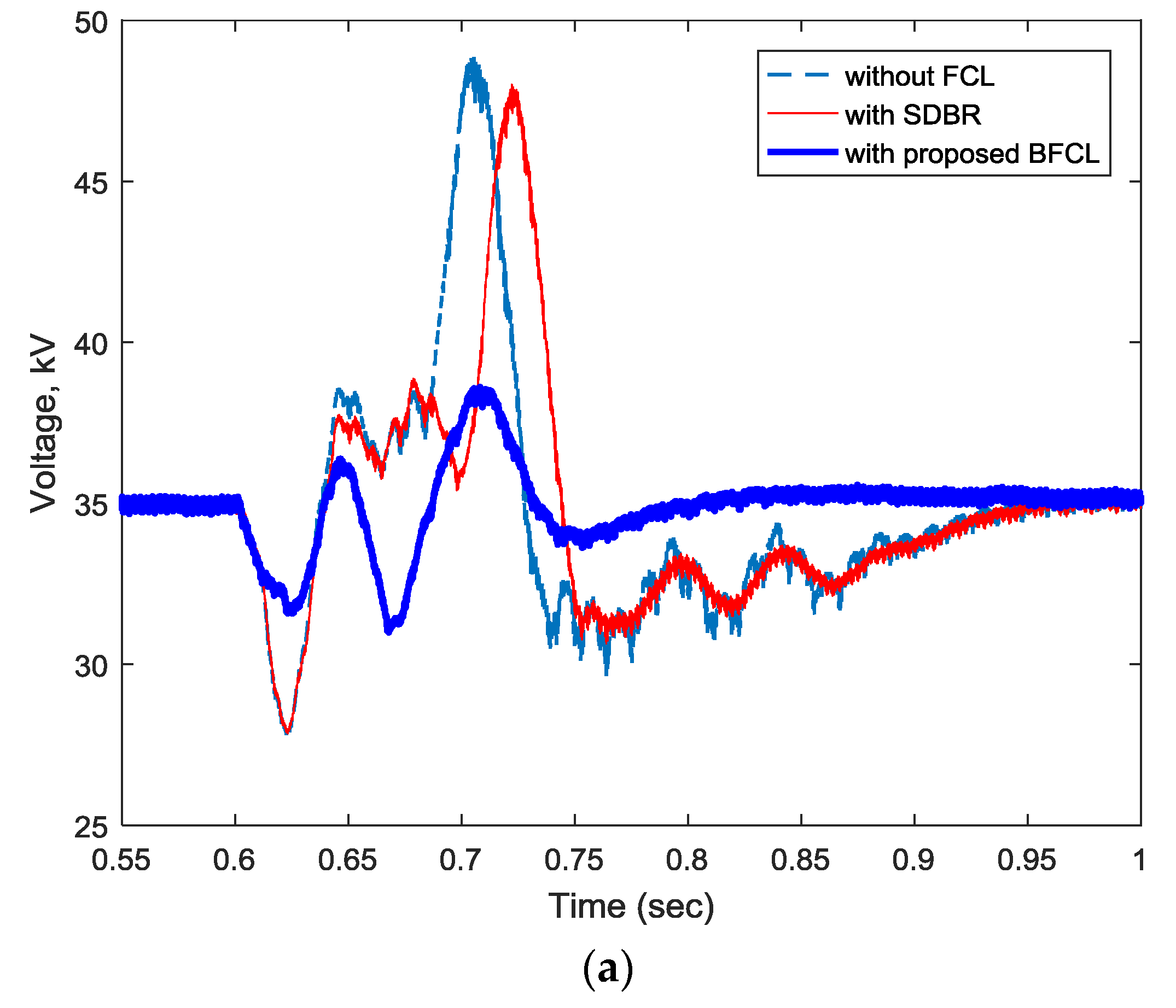
- DC link voltage fluctuation is greatly suppressed with the proposed BFCL.
- ▪
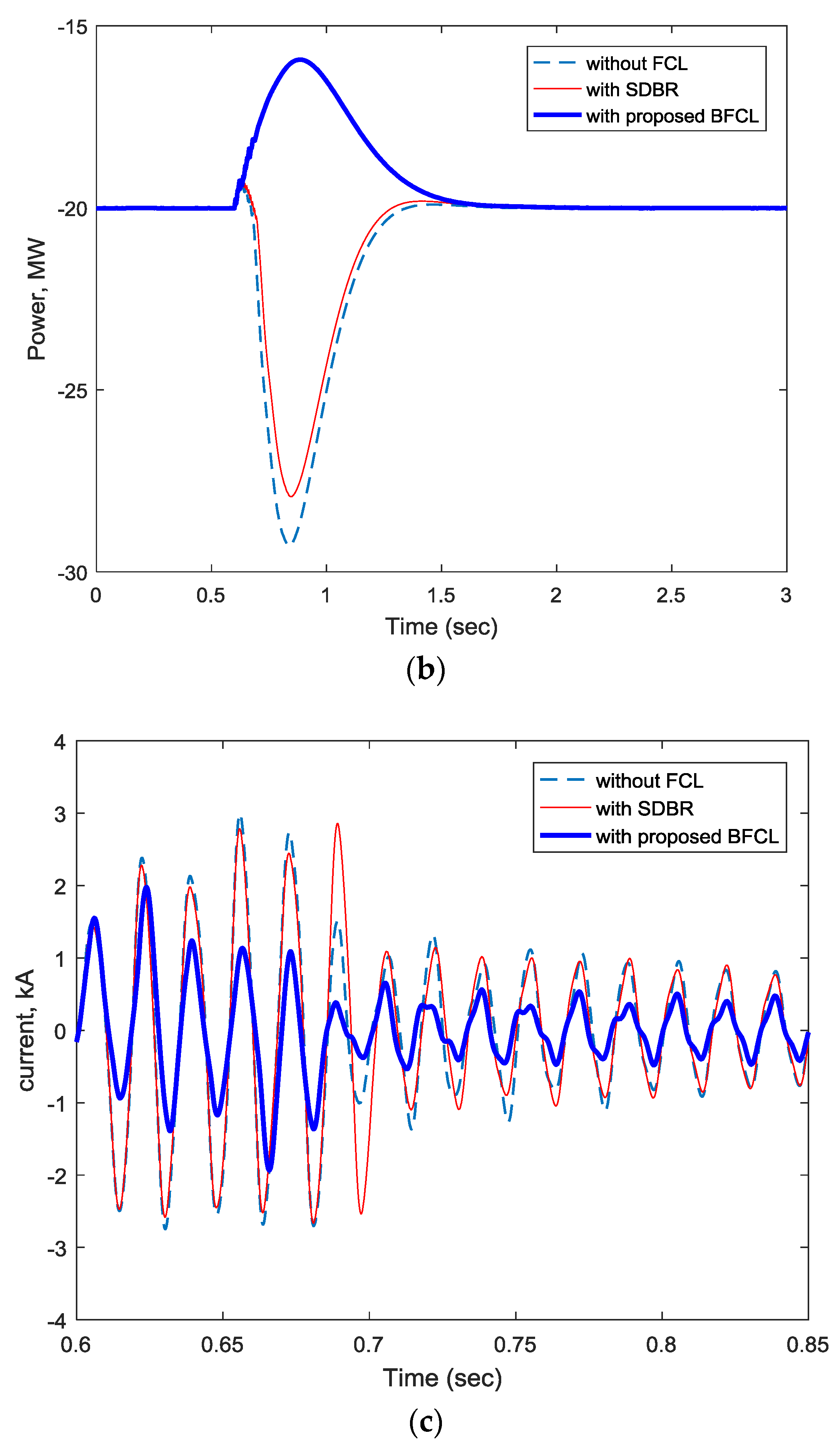
- Active power oscillation is significantly reduced with BFCL.
- ▪
- Wind generator speed oscillation is notably suppressed with BFCL in wind-integrated VSC-HVDC systems.
- ▪
- BFCL shows better performance over SDBR in all cases considered.
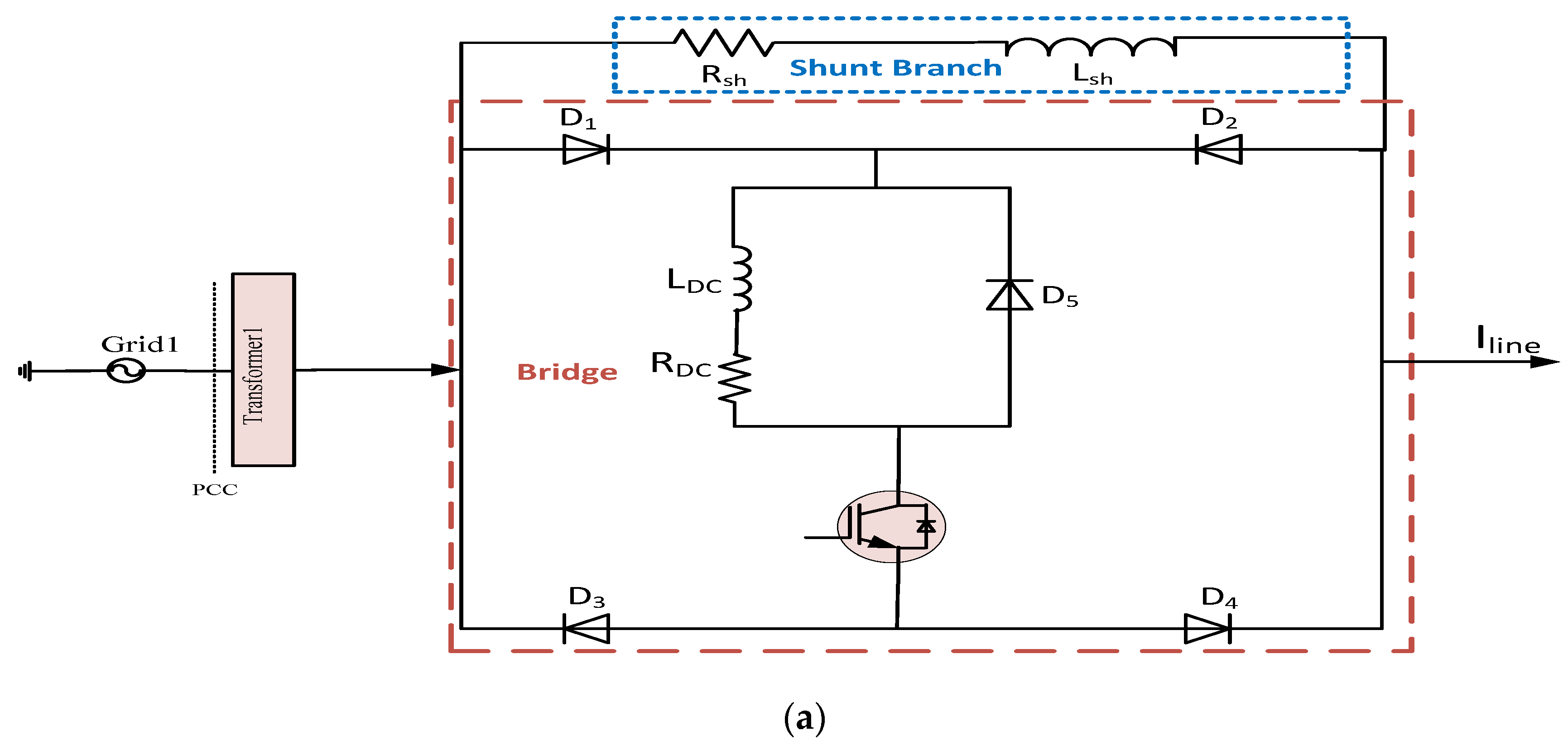
2. Bridge Type Fault Current Limiter
2.1. BFCL Structrue, Operation and Design Consideration
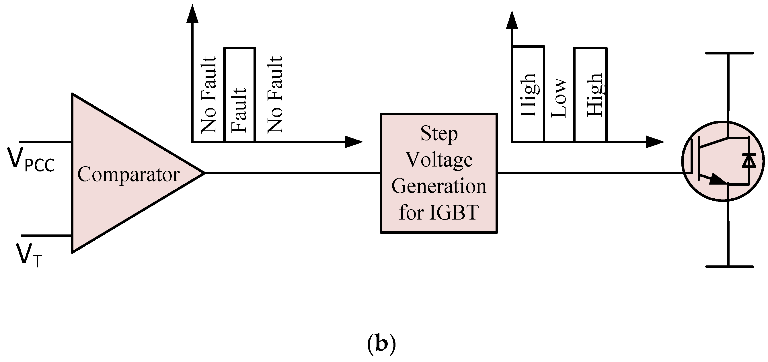
2.2. BFCL Control Technique
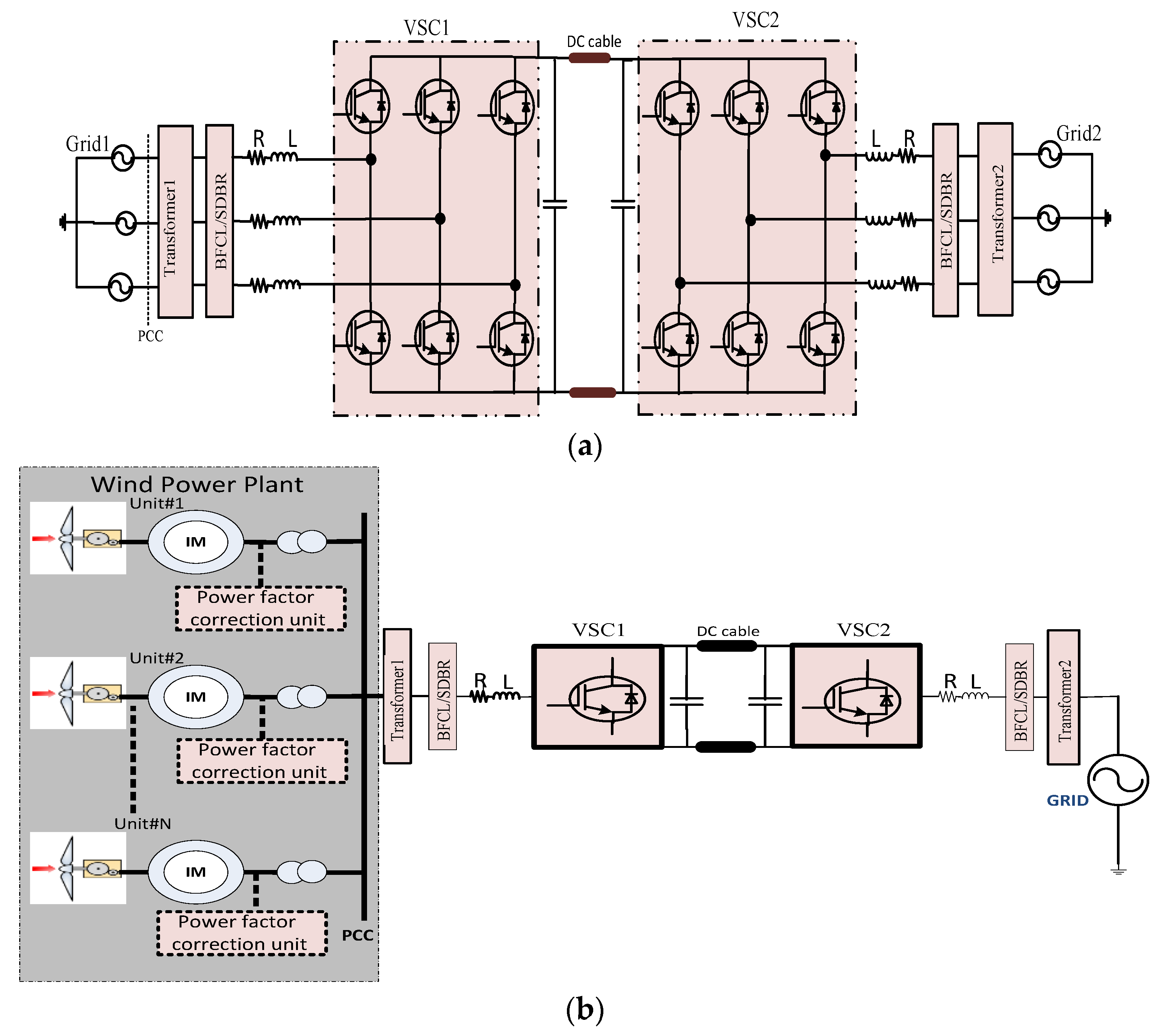
3. System Modelling and Controller Design
3.1. Wind Power Plant Modeling
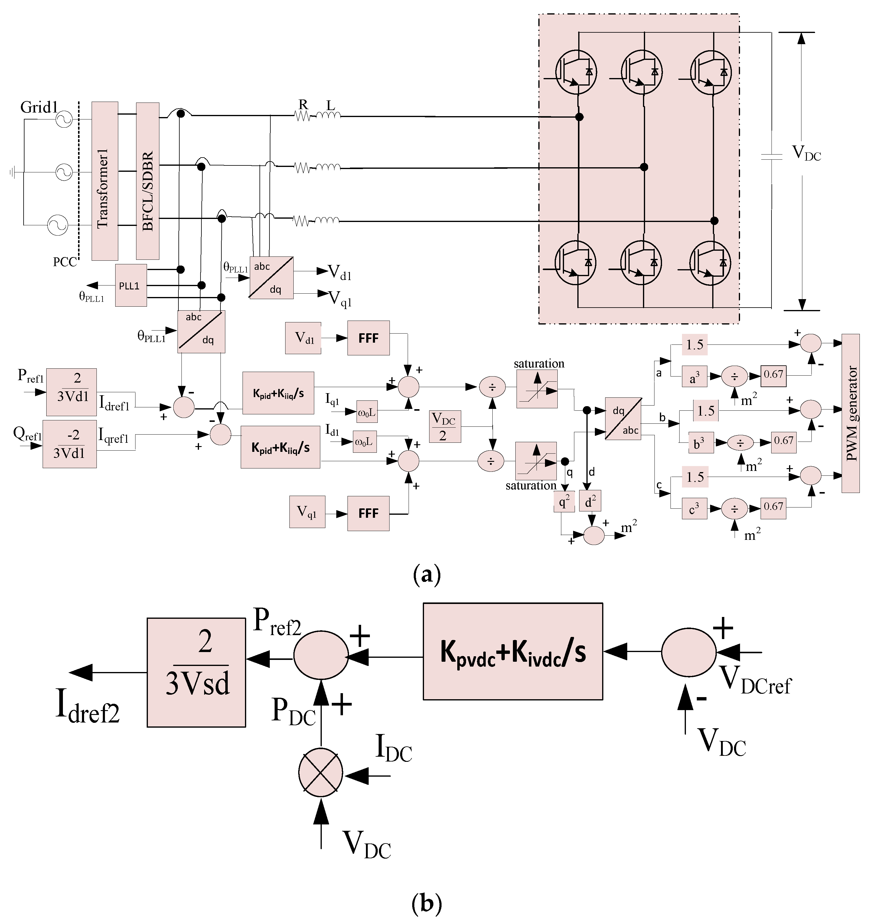
3.2. Control of VSC1
3.3. Control of VSC2
4. Results and Discussions
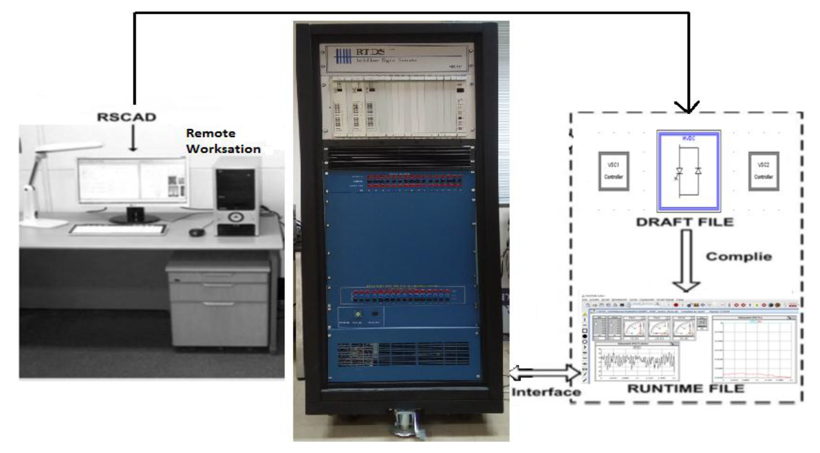
4.1. RTDS Implementation
4.2. Symmetrical Fault Application
4.2.1. Grids Connected VSC-HVSC System
4.2.2. Wind Farm Integrated VSC-HVSC System
4.3. Unsymmetrical Fault Application
4.3.1. Single Line to Ground Fault
4.3.2. Double Line to Ground Fault
4.4. Index-Based Comparison
5. Conclusions
Acknowledgments
Author Contributions
Conflicts of Interest
References
- Lazaros, P.L. Economic Comparison of HVAC and HVDC Solutions for Large Offshore Wind Farms under Special Consideration of Reliability; Citeseer X: Stockholm, Sweden, 2005. [Google Scholar]
- Eriksson, K.; Jonsson, T.; Tollerz, O. Small Scale Transmission to AC Networks by HVDC Light. In Proceedings of the 12th CEPSI conference, Pattaya, Thailand, 2–5 November 1998. [Google Scholar]
- Weimers, L. HVDC Light: A New Technology for a Better Environment. IEEE Power Eng. Rev. 1998, 18, 19–20. [Google Scholar] [CrossRef]
- Friedrich, K. Modern HVDC PLUS application of VSC in Modular Multilevel Converter topology. IEEE Int. Symp. Ind. Electron. 2010, 3807–3810. [Google Scholar] [CrossRef]
- Daoud, M.I.; Massoud, A.M.; Abdel-Khalik, A.S.; Elserougi, A.; Ahmed, S. A Flywheel Energy Storage System for Fault Ride Through Support of Grid-Connected VSC HVDC-Based Offshore Wind Farms. IEEE Trans. Power Syst. 2016, 31, 1671–1680. [Google Scholar] [CrossRef]
- Lee, J.-G.; Khan, U.A.; Lim, S.-W.; Shin, W.; Seo, I.-J.; Lee, B.-W. Comparative study of superconducting fault current limiter both for LCC-HVDC and VSC-HVDC systems. Phys. C Supercond. Appl. 2015, 518, 149–153. [Google Scholar] [CrossRef]
- Moawwad, A.; El Moursi, M.S.; Xiao, W. Advanced Fault Ride-Through Management Scheme for VSC-HVDC Connecting Offshore Wind Farms. IEEE Trans. Power Syst. 2016, 31, 4923–4934. [Google Scholar] [CrossRef]
- Shuttleworth, R.; Cwikowski, O.; Barnes, M.; Beddard, A.; Chang, B. Fault current testing envelopes for VSC HVDC circuit breakers. IET Gener. Transm. Distrib. 2016, 10, 1393–1400. [Google Scholar]
- Agarwal, S.; Swetapadma, A.; Panigrahi, C. An Improved Method Using Artificial Neural Network for Fault Detection and Fault Pole Identification in Voltage Source Converter-Based High-Voltage Direct Current Transmission Lines. Arab. J. Sci. Eng. 2017, 42, 1–14. [Google Scholar] [CrossRef]
- Elansari, A.S.; Finney, S.J.; Burr, J.; Edrah, M.F. Frequency control capability of VSC-HVDC transmission system. In Proceedings of the 11th IET International Conference on AC and DC Power Transmission, Birmingham, UK, 10–12 February 2015. [Google Scholar]
- Beddard, A.; Barnes, M. Modelling of MMC-HVDC Systems—An Overview. Energy Procedia 2015, 80, 201–212. [Google Scholar] [CrossRef]
- Kalcon, G.; Adam, G.P.; Anaya-Lara, O.; Burt, G.; Lo, K.L. Analytical efficiency evaluation of two and three level VSC-HVDC transmission links. Int. J. Electr. Power Energy Syst. 2013, 44, 1–6. [Google Scholar] [CrossRef]
- Van Hertem, D.; Ghandhari, M. Multi-terminal VSC HVDC for the European supergrid: Obstacles. Renew. Sustain. Energy Rev. 2010, 14, 3156–3163. [Google Scholar] [CrossRef]
- Xu, L.; Yao, L. DC voltage control and power dispatch of a multi-terminal HVDC system for integrating large offshore wind farms. IET Renew. Power Gener. 2011, 5, 223. [Google Scholar] [CrossRef]
- Yassin, H.M.; Hallouda, M.M.; Hanafy, H.H. Enhancement low-voltage ride through capability of permanent magnet synchronous generator-based wind turbines using interval type-2 fuzzy control. IET Renew. Power Gener. 2016, 10, 339–348. [Google Scholar] [CrossRef]
- Li, R.; Xu, L.; Guo, D. Accelerated Switching Function Model of Hybrid MMCs for HVDC System Simulation. IET Power Electron. 2017, 1–12. [Google Scholar] [CrossRef]
- Erlich, I.; Feltes, C.; Shewarega, F. Enhanced voltage drop control by VSC-HVDC systems for improving wind farm fault ridethrough capability. IEEE Trans. Power Deliv. 2014, 29, 378–385. [Google Scholar] [CrossRef]
- Feltes, C.; Wrede, H.; Koch, F.W.; Erlich, I. Enhanced fault ride-through method for wind farms connected to the grid through VSC-based HVDC transmission. IEEE Trans. Power Syst. 2009, 24, 1537–1546. [Google Scholar] [CrossRef]
- Nanou, S.I.; Papathanassiou, S.A. Grid Code Compatibility of VSC-HVDC Connected Offshore Wind Turbines Employing Power Synchronization Control. IEEE Trans. Power Syst. 2016, 31, 5042–5050. [Google Scholar] [CrossRef]
- Chaudhary, S.K.; Teodorescu, R.; Rodriguez, P.; Kjaer, P.C.; Gole, A.M. Negative sequence current control in wind power plants with VSC-HVDC connection. IEEE Trans. Sustain. Energy 2012, 3, 535–544. [Google Scholar] [CrossRef]
- Chen, L.; Chen, H.; Yang, J.; Yu, Y.; Zhen, K.; Liu, Y.; Ren, L. Coordinated control of superconducting fault current limiter and superconducting magnetic energy storage for transient performance enhancement of grid-connected photovoltaic generation system. Energies 2017, 10, 56. [Google Scholar] [CrossRef]
- Ito, D.; Yoneda, E.S.; Tsurunaga, K.; Tada, T.; Hara, T.; Ohkuma, T.; Yamamoto, T. 6.6 kV/1.5 kA-class superconducting fault current limiter development. IEEE Trans. Magn. 1992, 28, 438–441. [Google Scholar]
- Willen, D.W.A.; Cave, J.R. Short circuit test performance of inductive high T/sub c/ superconducting fault current limiters. IEEE Trans. Appl. Supercond. 1995, 5, 1047–1050. [Google Scholar] [CrossRef]
- Lim, S.-H.; Choi, H.-S.; Chung, D.-C.; Jeong, Y.-H.; Han, Y.-H.; Sung, T.-H.; Han, B.-S. Fault Current Limiting Characteristics of Resistive Type SFCL Using a Transformer. IEEE Trans. Appl. Supercond. 2005, 15, 2055–2058. [Google Scholar] [CrossRef]
- Byung, C.S.; Dong, K.P.; Jung-Wook, P. Tae Kuk Ko Study on a Series Resistive SFCL to Improve Power System Transient Stability: Modeling, Simulation, and Experimental Verification. IEEE Trans. Ind. Electron. 2009, 56, 2412–2419. [Google Scholar] [CrossRef]
- Noe, M.; Hobl, A.; Tixador, P.; Martini, L.; Dutoit, B. Conceptual Design of a 24 kV, 1 kA Resistive Superconducting Fault Current Limiter. IEEE Trans. Appl. Supercond. 2012, 22, 5600304. [Google Scholar] [CrossRef]
- Elschner, S.; Kudymow, A.; Fink, S.; Goldacker, W.; Grilli, F.; Schacherer, C.; Hobl, A.; Bock, J.; Noe, M. ENSYSTROB—Resistive Fault Current Limiter Based on Coated Conductors for Medium Voltage Application. IEEE Trans. Appl. Supercond. 2011, 21, 1209–1212. [Google Scholar] [CrossRef]
- Lee, S.; Yoon, J.; Yang, B.; Moon, Y.; Lee, B. Analysis model development and specification proposal of 154kV SFCL for the application to a live grid in South Korea. Phys. C Supercond. 2014, 504, 148–152. [Google Scholar] [CrossRef]
- Lee, J.-G.; Khan, U.A.; Hwang, J.-S.; Seong, J.-K.; Shin, W.-J.; Park, B.-B.; Lee, B.-W. Assessment on the influence of resistive superconducting fault current limiter in VSC-HVDC system. Phys. C Supercond. Appl. 2014, 504, 163–166. [Google Scholar] [CrossRef]
- Chen, L.; Pan, H.; Deng, C.; Zheng, F.; Li, Z.; Guo, F. Study on the application of a flux-coupling-type superconducting fault current limiter for decreasing HVDC commutation failure. Can. J. Electr. Comput. Eng. 2015, 38, 10–19. [Google Scholar] [CrossRef]
- Li, B.; Jing, F.; Jia, J.; Li, B. Research on Saturated Iron-Core Superconductive Fault Current Limiters Applied in VSC-HVDC Systems. IEEE Trans. Appl. Supercond. 2016, 26, 1–5. [Google Scholar] [CrossRef]
- Zhang, L.; Shi, J.; Wang, Z.; Tang, Y.; Yang, Z.; Ren, L.; Yan, S.; Liao, Y. Application of a Novel Superconducting Fault Current Limiter in a VSC-HVDC System. IEEE Trans. Appl. Supercond. 2017, 27, 1–6. [Google Scholar] [CrossRef]
- Zamora, I.; Abarrategui, O.; Larruskain, D.M. Fault Current Limiters for VSC-HVDC systems. In Proceedings of the 10th IET International Conference on AC and DC Power Transmission (ACDC 2012), Birmingham, UK, 4–5 December 2012; pp. 1–6. [Google Scholar]
- Chang, B.; Cwikowski, O.; Pei, X.; Barnes, M.; Shuttleworth, R.; Smith, A.C. Impact of Fault Current Limiter on VSC-HVDC DC Protection. In Proceedings of the 12th IET International Conference on AC and DC Power Transmission (ACDC 2016), Beijing, China, 28–29 May 2016; pp. 1–6. [Google Scholar]
- Mourinho, F.A.; Motter, D.; Vieira, J.C.M.; Monaro, R.M.; Blond, S.P.L.; Zhang, M.; Yuan, W. Modeling and Analysis of Superconducting Fault Current Limiters Applied in VSC—HVDC Systems. In Proceedings of the IEEE Power and Energy General Meeting, Denver, CO, USA, 26–30 July 2015; pp. 1–5. [Google Scholar]
- Li, B.T.; Jia, J.F.; Li, B.; Zhang, Y.K. Fault Analysis of VSC-HVDC System with Saturated Iron-Core Superconductive Fault Current Limiter. In Proceedings of the IEEE International Conference on Applied Superconductivity and Electromagnetic Devices, Shanghai, China, 20–23 November 2015; pp. 388–390. [Google Scholar]
- Lee, J.; Khan, U.A.; Lee, H.; Lee, B.; Model, A.H.T. Impact of SFCL on the Four Types of HVDC Circuit Breakers by Simulation. IEEE Trans. Appl. Supercond. 2016, 26, 1–6. [Google Scholar] [CrossRef]
- Ahmed, W.; Manohar, P. DC line protection for VSC-HVDC system. In Proceedings of the 2012 IEEE International Conference on Power Electronics, Drives and Energy Systems (PEDES), Bengaluru, India, 16–19 December 2012; pp. 1–6. [Google Scholar]
- Sadi, M.A.H.; Ali, M.H. A fuzzy logic controlled bridge type fault current limiter for transient stability augmentation of multi-machine power system. IEEE Trans. Power Syst. 2016, 31, 602–611. [Google Scholar] [CrossRef]
- Sadi, M.A.H.; Ali, M.H. Transient stability enhancement by bridge type fault current limiter considering coordination with optimal reclosing of circuit breakers. Electr. Power Syst. Res. 2015, 124, 160–172. [Google Scholar] [CrossRef]
- Rashid, G.; Ali, M.H. Bridge-Type Fault Current Limiter for Asymmetric Fault Ride-Through Capacity Enhancement of Doubly Fed Induction Machine Based Wind Generator. IEEE Energy Convers. Congr. Expo. 2014, 29, 1903–1910. [Google Scholar]
- Hossain, E. A non-linear controller based new bridge type fault current limiter for transient stability enhancement of DFIG based Wind Farm. Electr. Power Syst. Res. 2017, 152, 466–484. [Google Scholar] [CrossRef]
- Ali, M.H.; Dougal, R.A. A closed-loop control based braking resistor for stabilization of wind generator system. In Proceedings of the IEEE SoutheastCon 2010 (SoutheastCon), Concord, NC, USA, 18–21 March 2010; pp. 264–267. [Google Scholar]
- Saluja, R.; Ghosh, S.; Ali, M.H. Transient stability enhancement of multi-machine power system by novel braking resistor models. In Proceedings of the IEEE Southeastcon, Jacksonville, FL, USA, 4–7 April 2013. [Google Scholar]
- Jafari, M.; Naderi, S.B.; Hagh, M.T.; Abapour, M.; Hosseini, S.H. Voltage Sag Compensation of Point of Common Coupling (PCC) Using Fault Current Limiter. IEEE Trans. Power Deliv. 2011, 26, 2638–2646. [Google Scholar] [CrossRef]
- Rashid, G.; Ali, M.H. Transient Stability Enhancement of Doubly Fed Induction Machine-Based Wind Generator by Bridge-Type Fault Current Limiter. IEEE Trans. Energy Convers. 2015, 30, 939–947. [Google Scholar] [CrossRef]
- Liu, X.; Wang, P.; Loh, P.C. A hybrid AC/DC microgrid and its coordination control. IEEE Trans. Smart Grid 2011, 2, 278–286. [Google Scholar]
- Slootweg, J.G.; Polinder, H.; Kling, W.L. Representing wind turbine electrical generating systems in fundamental frequency simulations. IEEE Trans. Energy Convers. 2003, 18, 516–524. [Google Scholar] [CrossRef]
- Li, R.; Xu, L.; Holliday, D.; Page, F.; Finney, S.J.; Williams, B.W. Continuous Operation of Radial Multiterminal HVDC Systems under DC Fault. IEEE Trans. Power Deliv. 2016, 31, 351–361. [Google Scholar] [CrossRef]
- Li, R.; Xu, D. Parallel Operation of Full Power Converters in Permanent-Magnet Direct-Drive Wind Power Generation System. IEEE Trans. Ind. Electron. 2013, 60, 1619–1629. [Google Scholar] [CrossRef]
- Wang, Z.-D.; Li, K.-J.; Ren, J.-G.; Sun, L.-J.; Zhao, J.-G.; Liang, Y.-L.; Lee, W.-J.; Ding, Z.-H.; Sun, Y. A Coordination Control Strategy of Voltage-Source-Converter-Based MTDC for Offshore Wind Farms. IEEE Trans. Ind. Appl. 2015, 51, 2743–2752. [Google Scholar] [CrossRef]
- Preitl, S.; Precup, R.-E. An Extension of Tuning Relations after Symmetrical Optimum Method for PI and PID Controllers. Automatica 1999, 35, 1731–1736. [Google Scholar] [CrossRef]
- Baek, S.-M.; Park, J.-W. Nonlinear parameter optimization of FACTS controller via real-time digital simulator. IEEE Ind. Appl. Soc. Annu. Meet. 2012, 49, 1–8. [Google Scholar]


| Parameter | Value |
|---|---|
| HVDC system power rating | 30 MVA |
| Grid voltage | 140 kV (l-l rms) |
| Frequency | 60 Hz |
| Transfer power rating | 30 MVA |
| Voltage ratio of the transformer | 140/18 kV (Delta/Y) |
| Leakage inductance of transformer referred to delta side | 110 mH |
| Interface resistor (R) and reactor (L) | 88 mΩ and 8.5 mH |
| DC cable length | 25 km |
| DC cable resistance, inductance, and capacitance | 6 mΩ/km, 0.8 mH/km, 0.20 µF/km |
| DC capacitance | 500 µF |
| Reference DC bus voltage | 35 kV |
| BFCL shunt resistor and inductor | 10 mΩ and 2 mH |
| RDC and LDC of BFCL | 0.1 mΩ and 0.1 mH |
| SDBR resistor | 10 mΩ |
| Inner current controller Kpid | 8.5 |
| Inner current controller Kiiq | 88 |
| Outer voltage controller Kpvdc | 0.1036 |
| Outer voltage controller Kivdc | 17.77 |
| Feed forward function (FFF) | 1/(1 + 7 × 10⁻⁶ s) |
| Parameter | Value |
|---|---|
| Rotor blade radius | 41 m |
| Wind speed (cut-in/nominal/cut-out) | 3.5/13/20 m/s |
| Nominal turbine speed | 14.4 rpm |
| Rated power | 1.65 MW |
| Induction machine | 6 pole, 1200 rpm |
| Induction machine speed at rated power | 1207 rpm |
| Rated slip | 0.00167 |
| Gear box ratio | 84.5 |
| Power factor correction capacitors | 499.4 kVAR |
| Stator resistance | 0.0077 Ω |
| Rotor resistance | 0.0062 Ω |
| Stator reactance | 0.0697 Ω |
| Magnetizing reactance | 3.454 Ω |
| Rotor reactance | 0.0834 Ω |
| Index Parameters, % | Values of Indices | ||
|---|---|---|---|
| Without FCL | SDBR | Proposed BFCL | |
| dcvolt | 3.1883 | 2.1935 | 0.35573 |
| acpow (grid1) | 19.2779 | 9.5683 | 0.69532 |
| linecurr (grid1) | 1.0323 | 0.73188 | 0.22665 |
| Index Parameters, % | Values of Indices | ||
|---|---|---|---|
| Without FCL | SDBR | Proposed BFCL | |
| dcvolt | 1.3456 | 0.30726 | 0.16663 |
| MACspeed | 2.0075 | 2.0069 | 2.0063 |
| linecurr (stator) | 1.0242 | 0.94548 | 0.8011 |
| Index Parameters, % | Values of Indices | ||
|---|---|---|---|
| Without FCL | SDBR | Proposed BFCL | |
| dcvolt | 0.21688 | 0.17779 | 0.12088 |
| acpow (grid1) | 0.11024 | 0.069492 | 0.030914 |
| linecurr (grid1) | 0.17433 | 0.17193 | 0.16587 |
| Index Parameters, % | Values of Indices | ||
|---|---|---|---|
| Without FCL | SDBR | Proposed BFCL | |
| dcvolt | 0.61458 | 0.57893 | 0.25341 |
| acpow (grid1) | 2.7937 | 2.2805 | 1.9214 |
| linecurr (grid1) | 0.25032 | 0.24543 | 0.13371 |
© 2017 by the authors. Licensee MDPI, Basel, Switzerland. This article is an open access article distributed under the terms and conditions of the Creative Commons Attribution (CC BY) license (http://creativecommons.org/licenses/by/4.0/).
Share and Cite
Shafiul Alam, M.; Abido, M.A.Y. Fault Ride-through Capability Enhancement of Voltage Source Converter-High Voltage Direct Current Systems with Bridge Type Fault Current Limiters. Energies 2017, 10, 1898. https://doi.org/10.3390/en10111898
Shafiul Alam M, Abido MAY. Fault Ride-through Capability Enhancement of Voltage Source Converter-High Voltage Direct Current Systems with Bridge Type Fault Current Limiters. Energies. 2017; 10(11):1898. https://doi.org/10.3390/en10111898
Chicago/Turabian StyleShafiul Alam, Md, and Mohammad Ali Yousef Abido. 2017. "Fault Ride-through Capability Enhancement of Voltage Source Converter-High Voltage Direct Current Systems with Bridge Type Fault Current Limiters" Energies 10, no. 11: 1898. https://doi.org/10.3390/en10111898
APA StyleShafiul Alam, M., & Abido, M. A. Y. (2017). Fault Ride-through Capability Enhancement of Voltage Source Converter-High Voltage Direct Current Systems with Bridge Type Fault Current Limiters. Energies, 10(11), 1898. https://doi.org/10.3390/en10111898