Article

Fault Ride-through Capability Enhancement of Voltage Source Converter-High Voltage Direct Current Systems with Bridge Type Fault Current Limiters

by
Md Shafiul Alam
and
Mohammad Ali Yousef Abido
*
Department of Electrical Engineering, King Fahd University of Petroleum & Minerals, Dhahran 31261, Saudi Arabia
*
Author to whom correspondence should be addressed.
Energies 2017, 10(11), 1898; https://doi.org/10.3390/en10111898
Submission received: 8 October 2017 / Revised: 8 November 2017 / Accepted: 15 November 2017 / Published: 18 November 2017
(This article belongs to the Section F: Electrical Engineering)

Abstract

:
This paper proposes the use of bridge type fault current limiters (BFCLs) as a potential solution to reduce the impact of fault disturbance on voltage source converter-based high voltage DC (VSC-HVDC) systems. Since VSC-HVDC systems are vulnerable to faults, it is essential to enhance the fault ride-through (FRT) capability with auxiliary control devices like BFCLs. BFCL controllers have been developed to limit the fault current during the inception of system disturbances. Real and reactive power controllers for the VSC-HVDC have been developed based on current control mode. DC link voltage control has been achieved by a feedback mechanism such that net power exchange with DC link capacitor is zero. A grid-connected VSC-HVDC system and a wind farm integrated VSC-HVDC system along with the proposed BFCL and associated controllers have been implemented in a real time digital simulator (RTDS). Symmetrical three phase as well as different types of unsymmetrical faults have been applied in the systems in order to show the effectiveness of the proposed BFCL solution. DC link voltage fluctuation, machine speed and active power oscillation have been greatly suppressed with the proposed BFCL. Another significant feature of this work is that the performance of the proposed BFCL in VSC-HVDC systems is compared to that of series dynamic braking resistor (SDBR). Comparative results show that the proposed BFCL is superior over SDBR in limiting fault current as well as improving system fault ride through (FRT) capability.

1. Introduction

In the electric power industry, alternating-current (AC) systems have been overwhelmingly dominant over the direct-current (DC) option for a long time. However, this scenario is changing in recent years with DC systems playing an ever increasing role in the overall power systems due to several potential benefits: long distance water crossing, lower losses, controllability, limit short circuit currents, lesser corona loss, and the fact they requires less insulation [1]. Voltage source converter (VSC)-based high voltage direct current (HVDC) transmission is increasing research interest in the study of the smart grid. The VSC-based HVDC concept was introduced by manufacturers in the late 1990s and this new technology was also named HVDC Light by ABB [2,3] and HVDC Plus [4] by Siemens. Compared to the classic line commutated converter HVDC (LCC-HVDC), the former has several potential benefits such as self-regulating control of active and reactive power, increased power quality, comfortable integration of large-scale wind farm, and easy operation with weak AC grids, no reactive power demand, and less operational cost [5,6,7,8,9].
Moreover, VSC-HVDC offers a solution for many problems faced nowadays by power networks such as network congestion, grid reinforcement, multi-terminal DC (MTDC) operation and asynchronous operations of two different grids [10]. Different types of VSC topologies are proposed in the literature [11,12] including two level, three level and multilevel converters for HVDC transmission. Multilevel means more than two voltage levels can be achieved in one phase leg, which reduces the switching times of valve and makes the voltage wave form closer to a sinusoidal curve. Line to neutral voltage waveforms of both two-level and three-level converters with PWM are discussed and compared in [12].
However, despite the numerous advantages, VSC-HVDC systems face difficulties in dealing with different grid faults [13]. Fault ride-through (FRT) capability enhancement is one of the main requirements for wind farm-integrated VSC-HVDC systems [14,15]. During system faults, bulk power interruptions must be avoided by keeping the HVDC system energized, otherwise, the system may face serious instability due to this bulk power interruption. Modular multilevel converter-based VSC-HVDC system topologies can provide enhanced fault ride-through capability [16]. In [17,18] FRT capability as well as transient stability improvement have been reported by applying various VSC control techniques. A power synchronization control technique has been proposed in [19] with coordination between wind turbines and HVDC controllers in order to achieve FRT and frequency response capabilities, relying solely on offshore frequency modulation. Power oscillations minimization and DC link ripples reduction have been presented [20] with a negative sequence current controller. However, the power from the sending end wind power plant is reduced to zero which results in serious stresses on the mechanical system.
The security and stability of electric power systems are becoming ever more significant for the future due to their complex nature. A prospective solution to the stability and security issues mentioned above is to employ fault current limiters. Different categories of fault current limiter such as resistive, inductive, superconducting, flux-lock, DC reactor, and resonance FCL [21,22,23,24,25] have been presented for limiting fault currents as well as improving the stability of power systems. Resistive-type and inductive-type FCLs provide approximately zero impedance under normal condition, while they provide high-impedance resistors or inductors under a fault condition. Recently, a number of practical superconducting fault current limiter (SFCL) devices have been successfully developed and demonstrated by in-grid tests. The current motivation on the applied superconductivity technology to build SFCL devices has been moving from the 10-kV distribution level [26,27] to the 100-kV transmission level [27,28].
So far, fault current limiters have been comprehensively studied and applied in AC power grids to limit fault currents and to improve the dynamic performance of the system. However, the application of FCLs in VSC-HVDC systems has not been fully investigated [29]. In [30], the authors introduced a flux-coupling-type superconducting FCL to reduce the possibility of commutation failure in classic LCC-HVDC systems. DC fault current amplitude, commutation voltage, commutation failure duration, and successive commutation reduction have been observed with this FCL. However, SFCL parameter optimization, economic performance analysis, design of electrical insulation are not yet investigated. Superconducting fault current limiters have been studied in VSC-HVDC systems [31,32,33,34,35,36,37]. A novel SFCL with both a superconducting coil and a resistance is presented for limiting rapidly growing current in VSC-HVDC systems during severe disturbances [32]. A DC protection scheme of multiterminal VSC-HVDC with resistive type SFCL was presented [34]. Resistive type SFCLs reduce the current rating of DC circuit breakers. Maximum fault current, dissipated energy stress on HVDC circuit breaker and interruption time have been reduced with SFCLs by absorbing the fault energy during system disturbances [37]. A resistive-type SFCL with a chopper controlled resistor was presented [38] for transient stability augmentation of VSC-HVDC systems. Reduction in DC link voltage fluctuation and current is observed with the offered resistive SFCL scheme.
Among the different types of FCLs the non-superconducting bride-type fault current limiter (BFCL) is a new technology offering the capability of limiting fault currents as well as improving the dynamic performance of the power grid [39,40]. Diodes and IGBT switches are required for BFCLs which can be implemented easily [41]. Moreover, inductor and resistor required for the current limiting part of the BFCL are non-superconducting in nature. This reduces the implementation cost greatly compared to superconducting fault current limiters [42]. However, to the best of the authors’ knowledge this innovative technology in enhancing FRT capability as well as the stability of VSC-HVDC systems has not been examined so far. Since the necessity of auxiliary devices in improving dynamic performance of VSC-HVDC systems cannot be ignored and cost of applications needs to be minimized, BFCL represents a potential solution in this regard. In conclusion, there is a lack of works exploring the potential of BFCL to enhance transient stability as well as the FRT capability of VSC-HVDC system.
This research proposes a BFCL-based approach for fault current reduction and fault ride-through capability enhancement as well as stability improvement of VSC-HVDC systems in different configurations of two-grids connected mode and wind farm integrated mode. To the best of our knowledge, the potential of BFCL has not been examined so far in VSC-HVDC to enhance system dynamic performance. Some literatures [43,44] have presented series dynamic braking resistor (SDBR) as a potential solution to limit fault current. In this work, the proposed BFCL for VSC-HVDC systems is compared with SDBR in order to show the effectiveness of BFCL to reduce fault currents and improve system stability. The main contributions of this research are as follows:
The proposed BFCL solution is able to limit fault currents of VSC-HVDC system for both symmetrical and unsymmetrical faults.
DC link voltage fluctuation is greatly suppressed with the proposed BFCL.
Active power oscillation is significantly reduced with BFCL.
Wind generator speed oscillation is notably suppressed with BFCL in wind-integrated VSC-HVDC systems.
BFCL shows better performance over SDBR in all cases considered.

2. Bridge Type Fault Current Limiter

In this work, BFCL is proposed as a potential solution to the fault problems in VSC-HVDC systems. Its structure, operation and control technique are described in the following subsections.

2.1. BFCL Structrue, Operation and Design Consideration

BFCL is composed of a bridge with a parallel shunt branch [39,45] as shown in Figure 1a.
The bridge part consists a diode rectifier, very small DC resistor and inductor with antiparallel diode, and an IGBT switch. The shunt branch consists of a series resistance and reactance. The main function of BFCL is to insert resistance and reactance by connecting its shunt branch with the line.
During normal operating conditions of the system, the IGBT switch is turned on by its controller, so for a positive half cycle, current conducts thorough the path D1-LDC-RDC-IGBT-D4. During a negative half cycle, current passes thorough the path D2-LDC-RDC-IGBT-D3. Therefore, for both the cycles, the current has a unified direction through LDC and RDC. Consequently, LDC is charged to the peak value of the line current and acts like a short circuit. Since the values of RDC and LDC are very small, insignificant voltage drops across them. Eventually, bridge is short circuited during normal system operation and it has no effect on this operating condition. On the other hand, during system disturbances, the IGBT switch is turned off by BFCL controller. As a result, the shunt branch is connected to the line by considering the open circuit of the bridge part. Insertion of this resistance and reactance during system disturbances limits fault currents and improves the dynamic stability of the VSC-HVDC system.
In this work, BFCL parameters are designed based on the pre-fault power flow through each line [46]. In order to have least effect of the fault on the system, BFCL should consume equal or higher amount of active power as the pre-fault value. Pre-fault power consumption by the BFCL is given as below:
P B F C L P G 3
P B F C L = V P C C 2 R s h R s h 2 + X s h 2
where PG, VPCC, Rsh and Xsh are power delivered by the grid or wind farm, voltage at point of common coupling (PCC), shunt resistance, and shunt reactance, respectively. The above two equations give the following expression:
R s h 3 V P C C 2 + 9 V P C C 4 4 P G 2 X s h 2 2 P G
The necessary condition for the Rsh to be a real value is as follows:
X s h < 1.5 V P C C 2 P G
The same approach is used to find the value of Rsh. For the BFCL to be practical, small values of LDC and RDC are chosen so that the voltage drop across them is negligible and the DC current flowing through them is smooth.

2.2. BFCL Control Technique

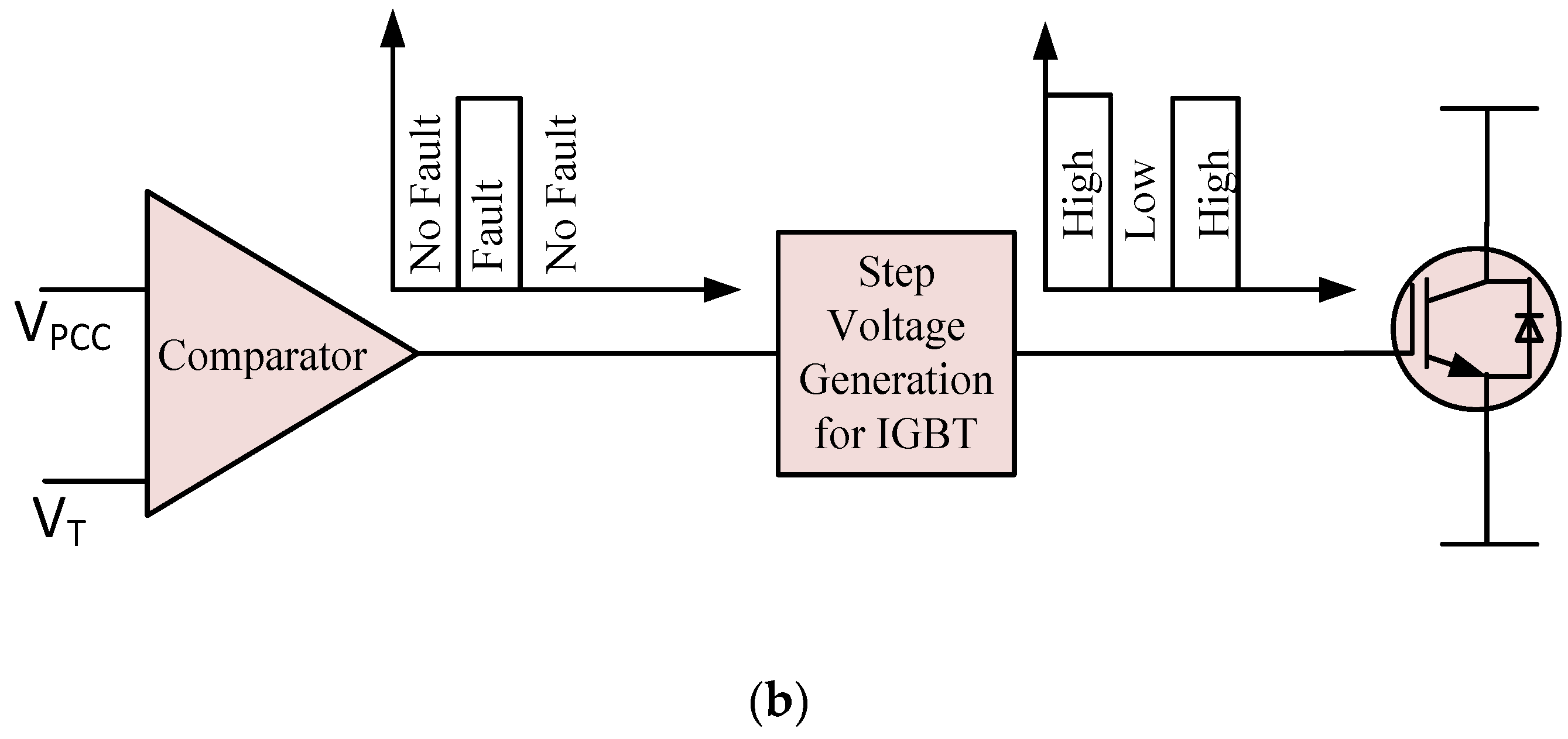
Disturbances in AC/DC systems can be detected either by voltage dips or by over-current at the point of common coupling (PCC) [47]. Voltage dip at the PCC has been used in this work to sense faults and generate IGBT gate control pulses as shown in Figure 1b. A comparator compares the PCC voltage (VPCC) with a predefined threshold voltage (VT). Under normal operating conditions when VPCC is higher than the VT, the comparator output goes on low, so the step voltage generation part of the BFCL controller generates a high voltage signal to make the IGBT switch on. During grid abnormalities VPCC decreases and becomes lower than VT, and as a result the comparator output becomes high. In this condition, a low voltage signal is generated by step voltage generation to turn off the IGBT. Consequently, the shunt branch of BFCL comes into operation to limit the fault current and enhance the system stability. Afterwards, when VPCC exceeds VT due to fault clearance or PCC voltage support by any compensation technique, IGBT receives a high voltage signal and consequently turns on. In this way, BFCL has no effect on normal operating condition and inserts resistance and reactance in order to limit fault current and augment fault ride-through capability of VSC-HVDC system. It is worth mentioning that during fault initiation the LDC line current tends to rise drastically; however, LDC limits this current. Therefore, the IGBT switch is protected from high di/dt.

3. System Modelling and Controller Design

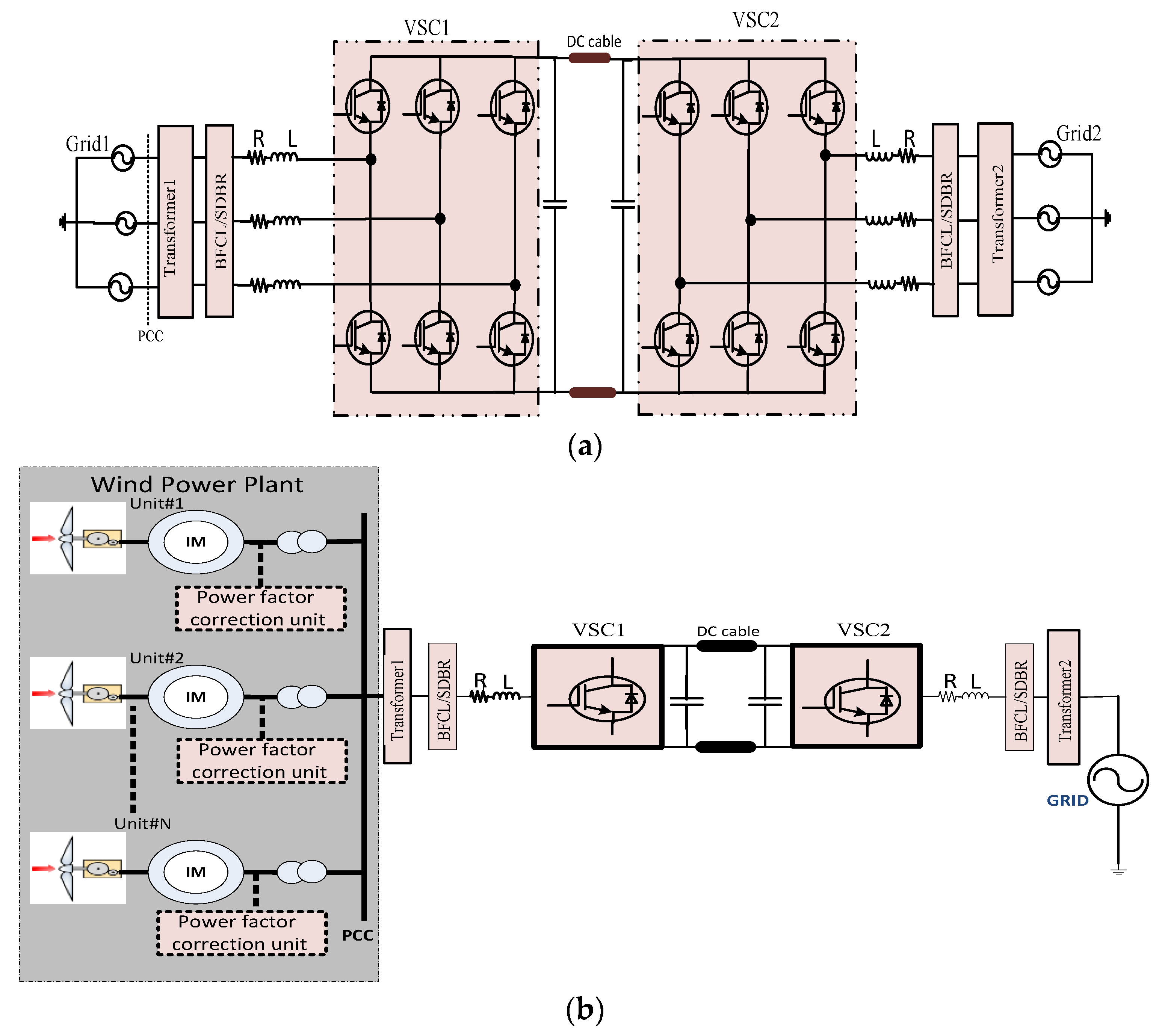
For transient stability and dynamic performance analysis, two grids connected VSC-HVDC system and fixed speed induction generators based wind farm integrated VSC-HVDC system as shown in Figure 2a,b, respectively, are modeled in this work.
A two grids connected VSC-HVDC system allows bidirectional power flow between the grids depending on the reference power, whereas, power transfer is unidirectional from the wind farm to the grid for a wind farm integrated VSC-HVDC system. For a HVDC system, the DC link voltage must be regulated at a prespecified value. The converter used in this work is a 2-level VSC. The VSC2controller regulates the DC bus voltage. The proposed control technique with BFCL is described in the following subsections.

3.1. Wind Power Plant Modeling

In order to model the wind turbine, the power coefficient (Cp) must be known to compute the amount of power produced by the turbine for a given wind speed. Cp is highly nonlinear function of pitch angle ( β ) and tip speed ratio ( λ ) whose analytical expression can be given by the following equation [48]:
C p ( λ , β ) = 1 2 ( λ 0.022 β 2 5.6 ) e 0.17 λ
Turbine blades are designed to stall if the wind speed exceeds a designed maximum. Active stall blades have the features that their pitch angle can be adapted dynamically to adjust their efficiency. The wind turbine is connected to the induction machine through a gear box as shown in Figure 2b. Torque is provided from the wind turbine model as input to the induction machine and induction machine provides shaft speed back to the turbine model.
A number of capacitor banks equipped with switches are connected at the terminal of the induction machine. A control loop is designed among the switches in order to maintain power factor within a set-point range. Several wind generating units are connected at the point of common coupling (PCC) to achieve a desired power delivery to the grid through the HVDC link.

3.2. Control of VSC1

The function of the VSC1 controller is to regulate the active power exchange between grids or from the wind farm to a grid. In addition, the VSC1 controller can regulate the reactive power exchange with the grid or wind farm to control the AC voltage at the PCC. According to instantaneous power theory active power and reactive power in terms of d-q quantities are given as follows:
P s = 3 2 [ V d I d + V q I q ]
Q s = 3 2 [ V d I q + V q I d ]
The function of phase locked loop (PLL) is to regulate V q at zero, so putting V q = 0 in the above equations, the following equations can be written:
P s = 3 2 V d I d
Q s = 3 2 V d I q
Therefore, direct axis current controls the active power and quadrature axis current controls the reactive power independently given as:
I d r e f = 2 3 V d P r e f
I q r e f = 2 3 V d Q r e f
Using a-b-c to d-q transformation and assuming steady state operation condition, we have following set of equations for voltage source converter (VSC) of Figure 2:
L d I d d t = L ω 0 I q R I d + V t d V d
L d I q d t = L ω 0 I d R I q + V t q V q
V t d = V D C 2 m d
V t q = V D C 2 m q
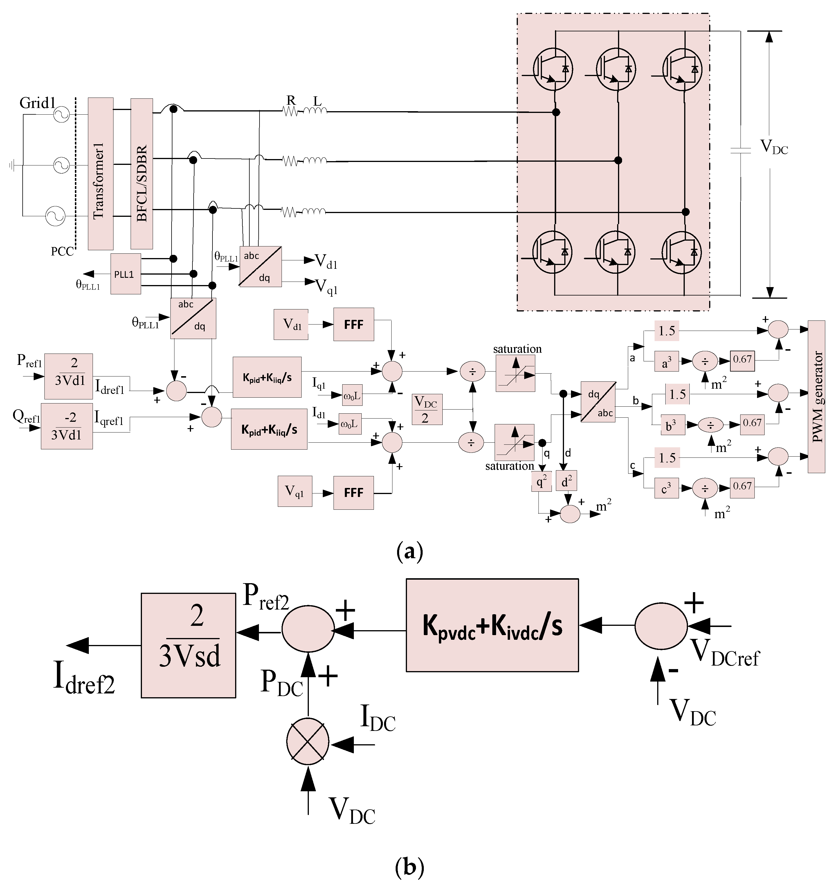
Using the above set of equations and the third harmonic injected PWM technique, the VSC1 controller has been developed as shown in Figure 3a to control active and reactive power. As shown in Figure 3a active and reactive power are controlled by an inner current controller with corresponding direct and quadrature current control. PI controllers are used for both the direct axis and quadrature axis currents. The pole-zero cancellation technique has been used to tune the inner current controller parameters. Undesirable start-up transients have been avoided by augmenting the control scheme with a feed forward filter (FFF). The third harmonic injected PWM technique is used to make the VSC voltage remain within permissible limits.

3.3. Control of VSC2

Among several control strategies, DC voltage control is the main aspect of the VSC-HVDC system analogous to the frequency control in classic AC power system. The system stability is greatly influenced by DC link capacitance [49] and control of voltage across DC links [50,51]. DC bus voltage can be considered as constant only during switching period as this period is usually very short [50]. VSC2 has two controllers: an outer controller for regulating the DC link voltage and an inner controller for regulating the current. VSC2 has a similar inner current controller as shown in Figure 3a, except that the Pref for VSC2 controller is provided by an outer DC link voltage controller. The outer DC link voltage controller for VSC2 is shown in Figure 3b. In the outer DC link voltage controller, the measured DC link voltage (VDC) is compared with a reference DC link voltage (VDCref) and the error is controlled by a proportional-integral (PI) controller. PI parameters have been tuned with symmetrical optimum method [52]. PI controller output is added with power exchange between two grids or wind farm and grid (PDC) to generate reference active power for VSC2.

4. Results and Discussions

4.1. RTDS Implementation

Test systems of Figure 2 are implemented in a real time digital simulator (RTDS) to validate the effectiveness of proposed BFCL solution. BFCL is also compared with SDBR to show the improvement of systems performance in limiting fault current. The same value of resistors is used for both BFCL and SDBR for fair comparison. Details of the VSC-HVDC system (with controllers) and wind system data are listed in Table 1 and Table 2, respectively.
RTDS operates in real time and is a fully digital power system simulator [53]. It continuously produces output conditions that accurately characterize the conditions in the real network by solving the power system equations. In RTDS, the small-time step (2 μs) is used to simulate the power electronic devices while the power components are represented by large-time step (50 μs). Thus, RTDS has widely been recognized as an ideal tool for the design, development, and testing of power control and protection schemes.
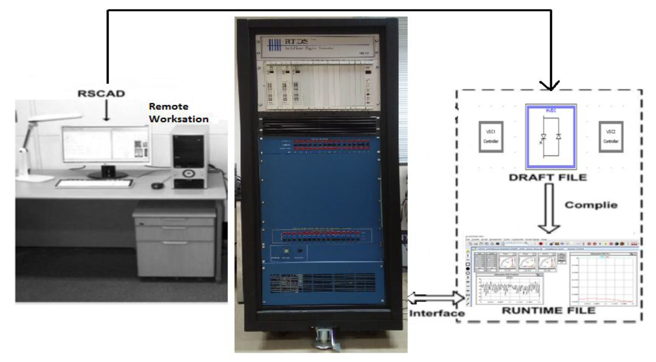
As shown in Figure 4, RTDS is connected to a workstation computer via a network hub. A system network is created in RSCAD software and saved as a draft file. Afterwards, this file is compiled and downloaded in RTDS. In addition to the draft module, RSCAD provides a runtime module for monitoring network behavior in real time. The subsequent sections present the detailed RTDS implementation results.
Initially, the systems are considered to be operated under their normal conditions. Then, a symmetrical three line to ground (3LG) fault and different unsymmetrical faults: single line to ground (1LG) fault and double line to ground (2LG) fault are applied. Three different simulation cases are considered: without FCL; with SDBR; and with proposed BFCL.

4.2. Symmetrical Fault Application

4.2.1. Grids Connected VSC-HVSC System

Initially, DC capacitors are discharged by disconnecting the HVDC system from both grid and gate pulses of VSC1 and VSC2 are blocked with all controllers in inactive conditions. Then, the HVDC system is connected to the grid through the transformers, so the capacitors are charged gradually to a voltage level of around 25 kV through the antiparallel diodes of VSCs. Afterwards, the DC link reference voltage is set to 35 kV. As a result, the DC link voltage reaches 35 kV by the control action of the outer DC link voltage controller of VSC2. Now, 20 MW power is transferred from grid1 to grid2 by changing the reference power (Pref1) command of VSC1. Different types of faults are then applied in the system at grid1. DC link voltage, line active power, and line current are presented and compared for both cases of SDBR and proposed BFCL. All faults have been applied for six cycles.
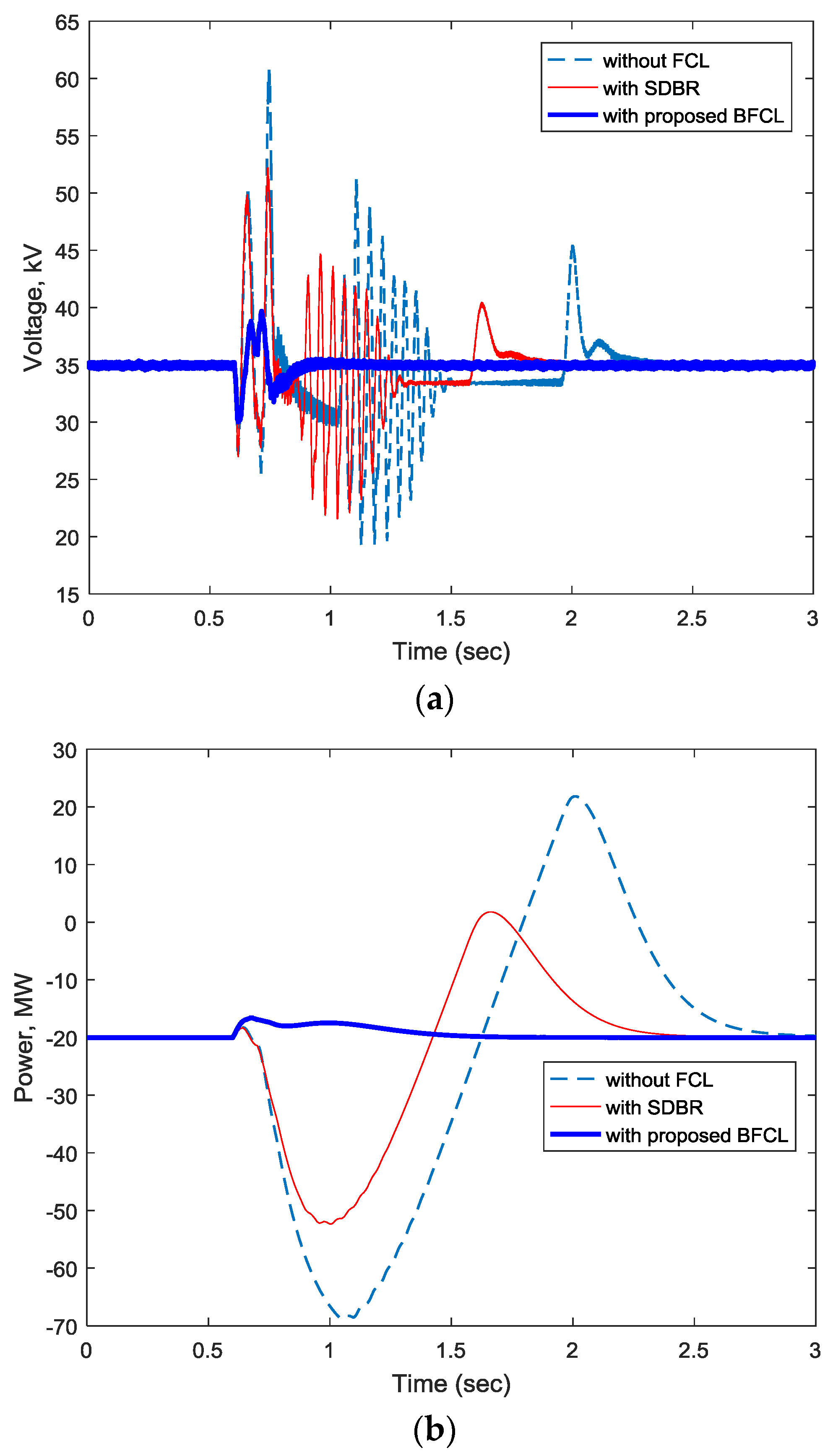
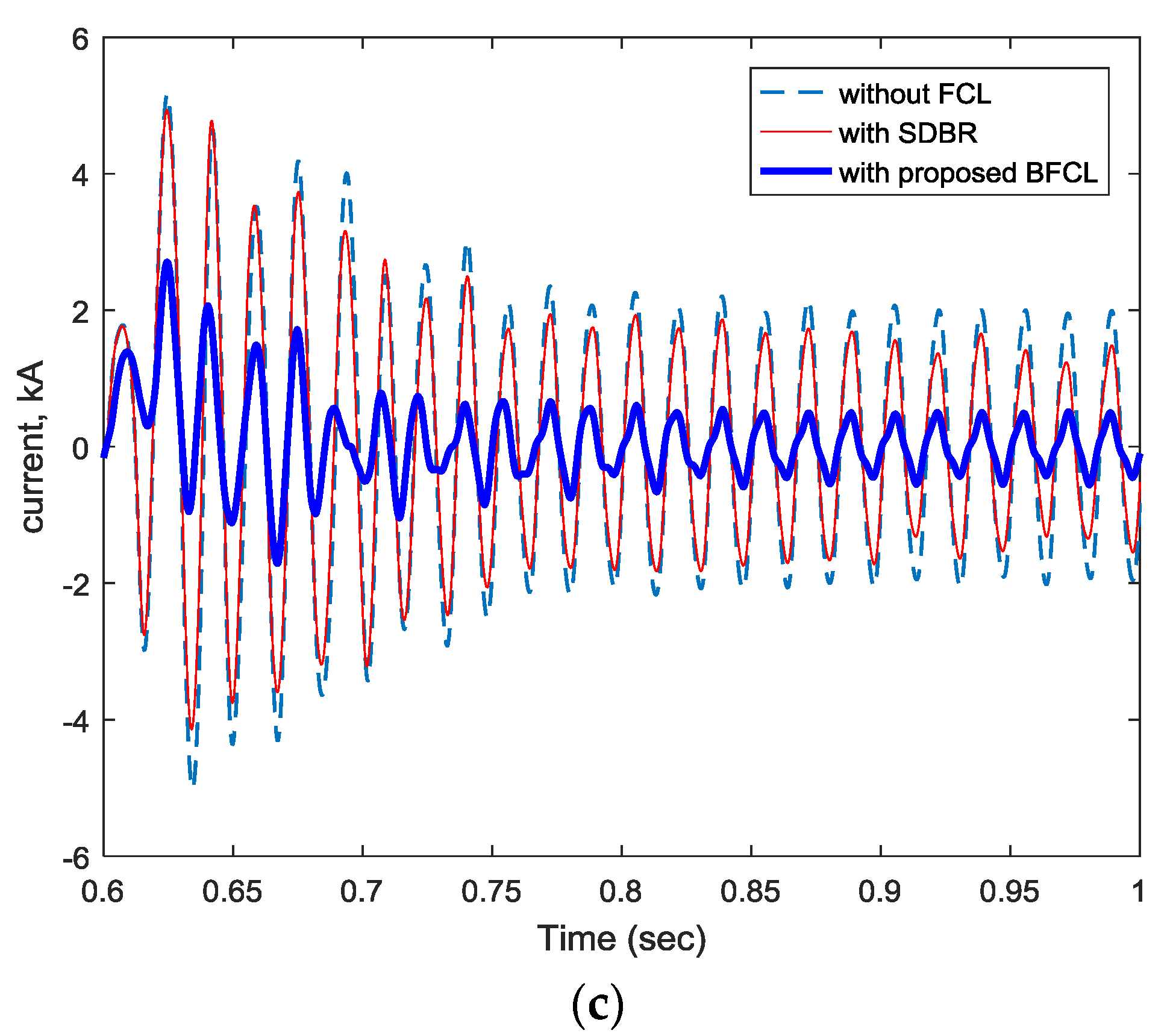
Figure 5 shows the transient response improvement of VSC-HVDC system with symmetrical three phase fault applied in grid1. Figure 5a shows that DC link voltage fluctuates from 17 kV to 61 kV without any auxiliary controller. This fluctuation is reduced with the SDBR controller to the range of 19 kV to 53 kV. However, the DC link voltage oscillation is greatly suppressed with the proposed BFCL controller keeping the voltage fluctuation from 29 kV to 39 KV. Moreover, DC link voltage reaches its reference value of 35 kV at 0.8 s whereas it takes 2 s with SDBR and 2.4 s without any FCL. Power oscillation minimization and fault current limiting capability of the proposed BFCL solution have been clearly visualized in Figure 5b,c, respectively, for a 3LG fault at grid1.
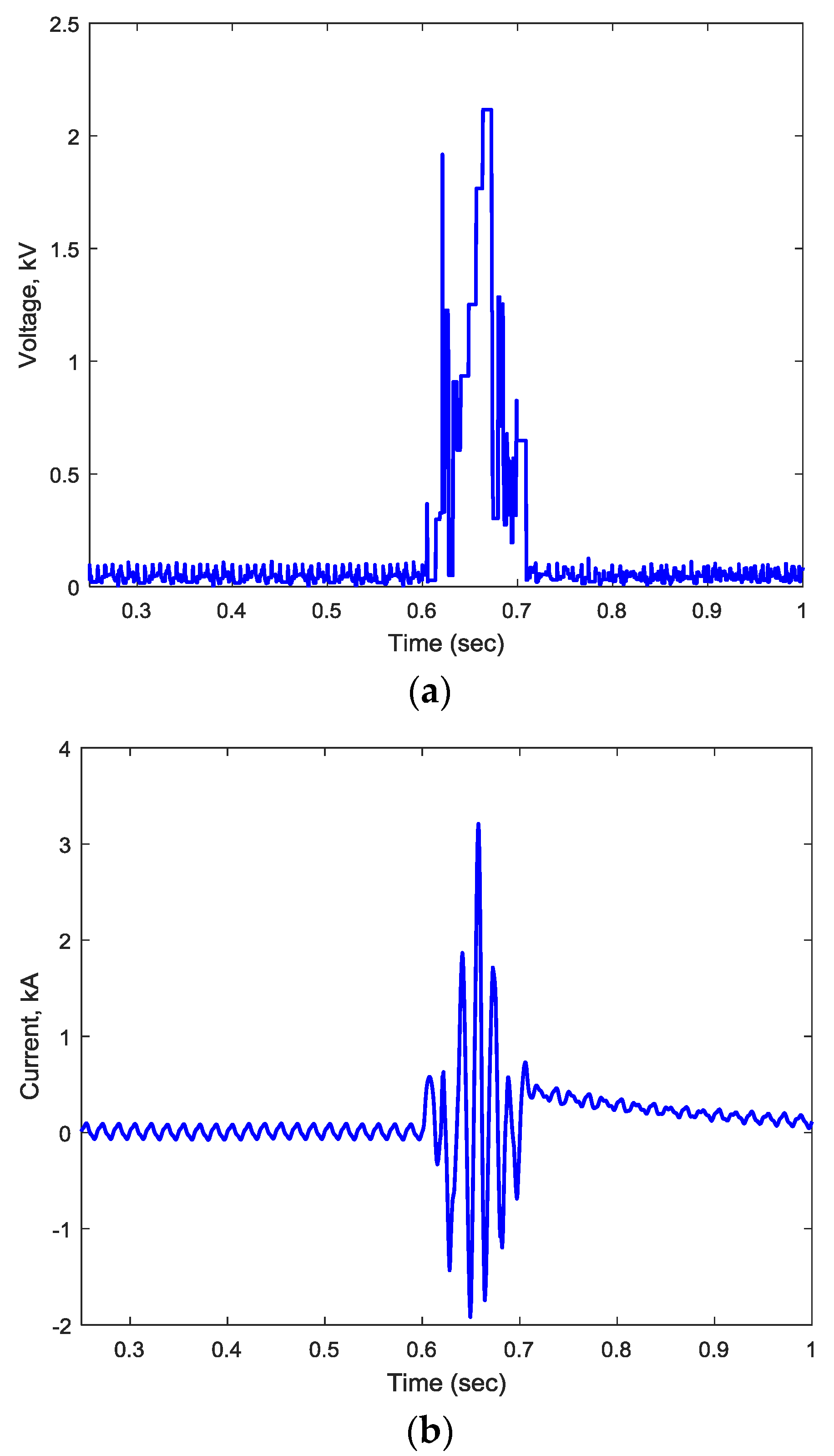
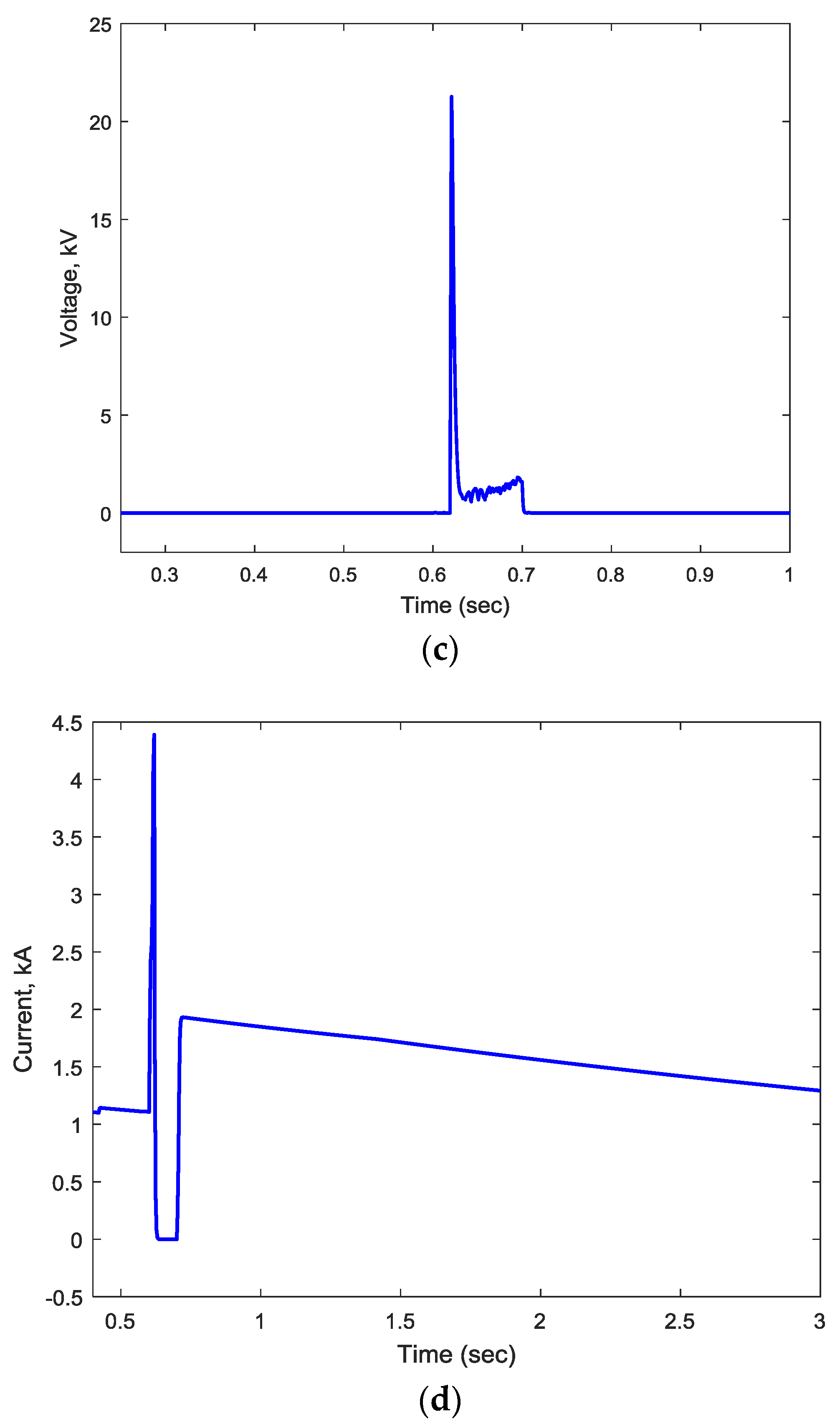
Detailed voltage and current stresses across of shunt branch and IGBT switch of BFCL during three phase symmetrical fault are clearly visualized in Figure 6a–d.

4.2.2. Wind Farm Integrated VSC-HVSC System

A three phase symmetrical fault is applied to wind farm integrated VSC-HVDC system. Figure 7a shows that induction machine speed fluctuates over a wide range of 1205 RPM to 1218 RPM without any auxiliary controller for symmetrical fault applied at PCC. System performance improvement is observed by the slight speed fluctuation reduction with SDBR. However, machine speed oscillation is greatly damped with the proposed BFCL controller. Moreover, the machine speed reaches to its steady state value at 0.9 s with BFCL whereas it takes 1.5 s with SDBR. Without any controller the machine speed reaches to its steady state value at around 2.3 s. Machine stator fault current reduction and DC link voltage oscillation minimization with the proposed BFCL solution have been clearly visualized in Figure 7b,c, respectively, for a 3LG fault at the PCC.

4.3. Unsymmetrical Fault Application

Different types of unsymmetrical faults have been applied in grid1 for a two grids-connected VSC-HVDC system. Real time simulation shows a positive effect to reduce DC link voltage oscillation, power oscillation and the fault current with the proposed BFCL.

4.3.1. Single Line to Ground Fault

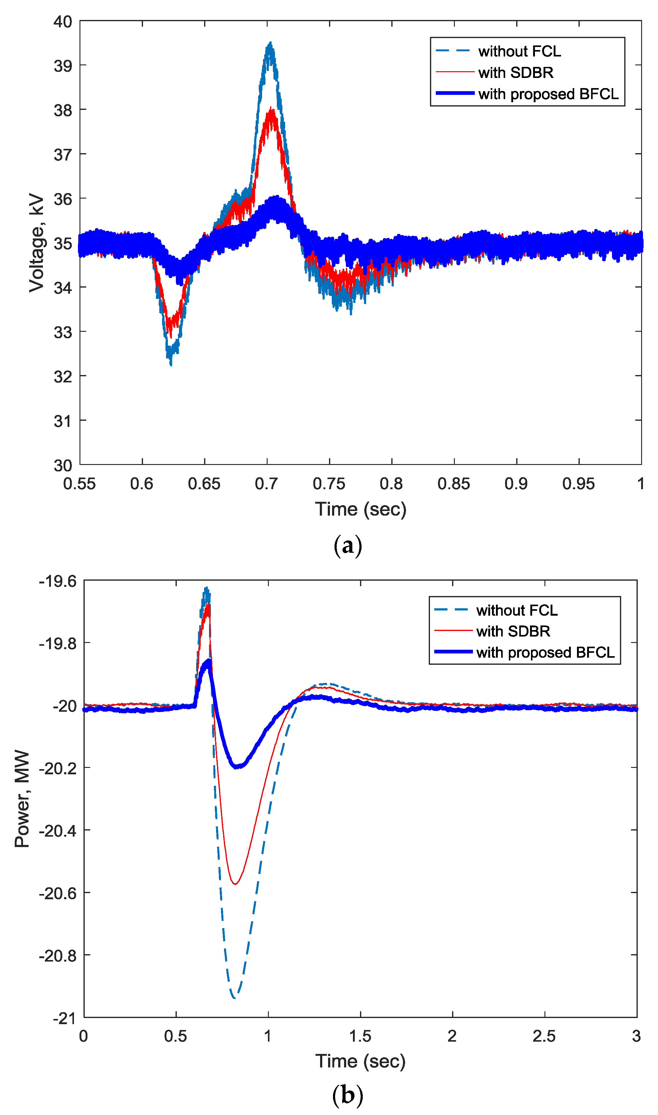
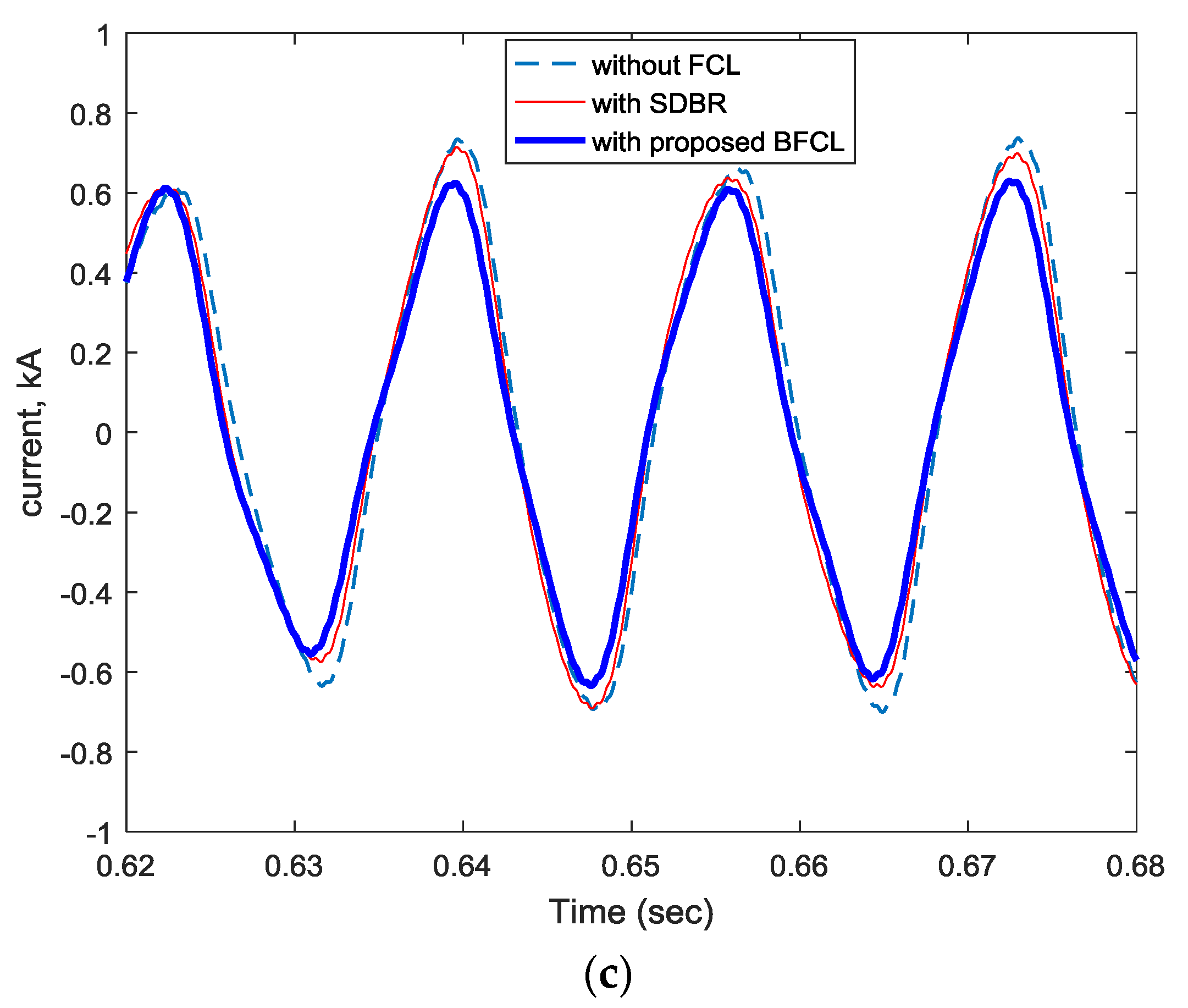
Figure 8a shows the DC link voltage response with 1LG fault applied at grid1 for a two grids connected VSC-HVDC system. Without FCL, the system has a high DC link voltage overshoot. Application of SDBR reduces this overshoot by 31.03%. However, a great reduction in DC link voltage overshoot is observed with the proposed BFCL corresponding to a 72.14% reduction. Moreover, the settling time for the DC link voltage is higher for the system without any auxiliary controller. A very slight reduction in settling time is achieved by SDBR. However, the proposed BFCL reduces the settling time for the DC link voltage by 14.7%. A significant reduction in power oscillation and fault current is observed as shown in Figure 8b,c.

4.3.2. Double Line to Ground Fault

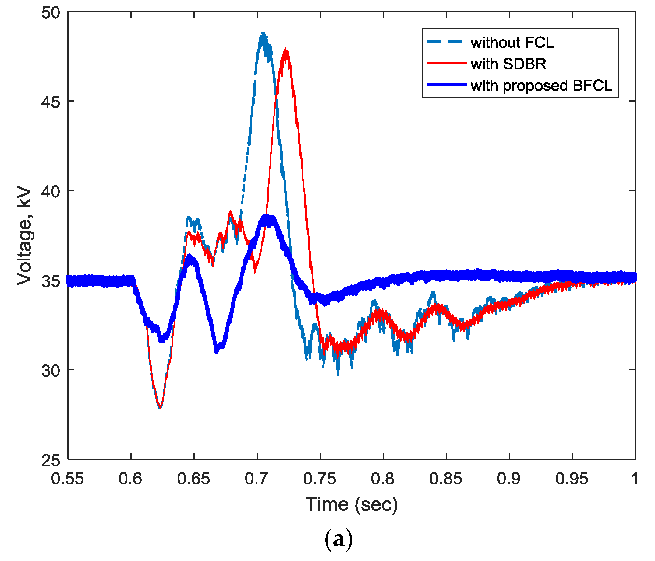
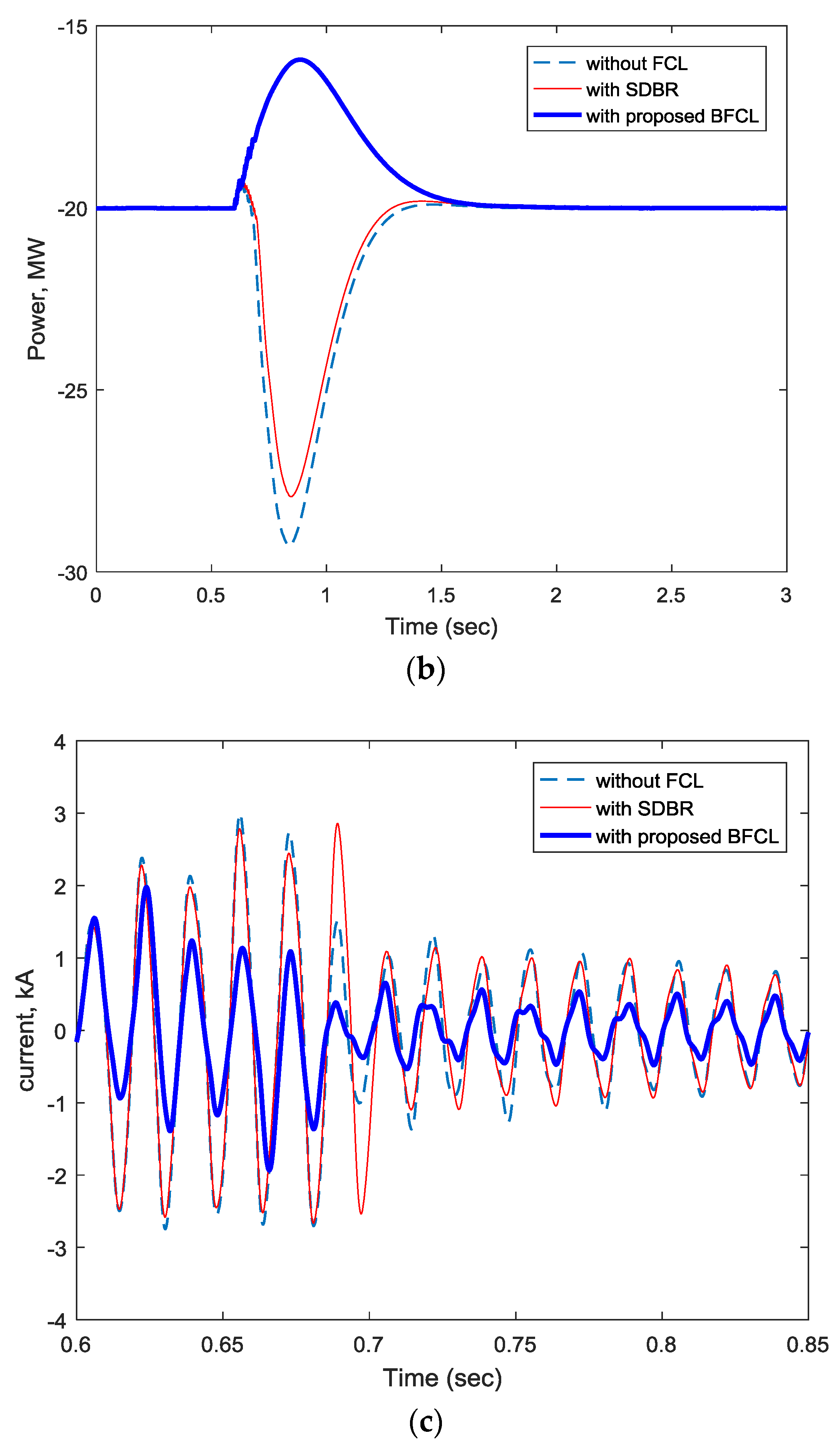
The fault current limiting capability of BFCL helps maintain the DC link voltage of a VSC-HVDC system as shown in Figure 9 for a double line to ground (2LG) fault. Without FCL and with SDBR the DC link voltage fluctuates widely between the range of 27 kV to 49 kV as shown in Figure 9a. However, the voltage fluctuation is greatly reduced with the BFCL. The DC link voltage lies within the range of 32 kV to 38 kV during a 2LG fault at grid1. The time taken by the system to bring the DC link voltage to its steady state value is 0.75 s with the proposed BFCL controller; whereas, this time is as long as 0.958 s without FCL and with SDBR. Figure 9b,c demonstrate the capability of BFCL in improving system power damping and reducing fault currents during 2LG faults at grid1.

4.4. Index-Based Comparison

Besides graphical representations, an index-based performance comparison is conducted to get a more clear perception of VSC-HVDC systems performance improvement with proposed BFCL controller. Several performance indices are considered, for example dcvolt, acpow, linecurr and MACspeed. Mathematical expressions for the abovementioned indices can be defined as follows:
d c v o l t = 0 T | Δ V d c | d t V d c _ r a t e d
a c p o w = 0 T | Δ P | d t P r a t e d
l i n e c u r r = 0 T | Δ i | d t i r a t e d
M A C s p e e d = 0 T | Δ N | d t N r a t e d
where Δ V d c , Δ P , Δ i and Δ N represent deviations of dc link voltage, active power flow, line current, and machine speed respectively.
Performance indices for symmetrical and different unsymmetrical faults are listed in the Table 3, Table 4, Table 5 and Table 6.
Based on the performance indices values of DC link voltage, active power flow, line current, and machine speed listed above, it can be concluded that the performance of the proposed BFCL is better in two grid-connected and fixed speed wind farm integrated VSC-HVDC systems during different faults.

5. Conclusions

In this work, BFCL has been proposed to limit fault currents as well as augment the fault ride-through capability of two grids-connected VSC-HVDC system and wind farm integrated VSC-HVDC systems. Real and reactive power controllers, and a DC voltage controller have been designed. Real time digital simulation of a HVDC plant, wind system, BFCL and their controllers have been developed in RTDS. The effectiveness of the proposed BFCL has been examined though the application of balanced and unbalanced faults. From the real time implementation results, BFCL has been found to be a very effective way of limiting fault currents and enhancing the dynamic performance of VSC-HVDC systems. The results demonstrate that the DC link voltage, power, fault current, and wind generator speed fluctuations have been substantially reduced with the proposed BFCL and associated controllers. The results also show that the proposed BFCL solution outperforms SDBR in terms of response overshoots and settling times under all disturbance conditions considered.

Acknowledgments

The authors would like to acknowledge the support provided by Deanship of Scientific Research, King Fahd University of Petroleum & Minerals, through the funded project # RG1420-1&2.

Author Contributions

All authors contributed to this work by collaboration. Md Shafiul Alam is the first author in this manuscript. All authors revised and approved for the publication.

Conflicts of Interest

The authors declare no conflict of interest.

References

  1. Lazaros, P.L. Economic Comparison of HVAC and HVDC Solutions for Large Offshore Wind Farms under Special Consideration of Reliability; Citeseer X: Stockholm, Sweden, 2005. [Google Scholar]
  2. Eriksson, K.; Jonsson, T.; Tollerz, O. Small Scale Transmission to AC Networks by HVDC Light. In Proceedings of the 12th CEPSI conference, Pattaya, Thailand, 2–5 November 1998. [Google Scholar]
  3. Weimers, L. HVDC Light: A New Technology for a Better Environment. IEEE Power Eng. Rev. 1998, 18, 19–20. [Google Scholar] [CrossRef]
  4. Friedrich, K. Modern HVDC PLUS application of VSC in Modular Multilevel Converter topology. IEEE Int. Symp. Ind. Electron. 2010, 3807–3810. [Google Scholar] [CrossRef]
  5. Daoud, M.I.; Massoud, A.M.; Abdel-Khalik, A.S.; Elserougi, A.; Ahmed, S. A Flywheel Energy Storage System for Fault Ride Through Support of Grid-Connected VSC HVDC-Based Offshore Wind Farms. IEEE Trans. Power Syst. 2016, 31, 1671–1680. [Google Scholar] [CrossRef]
  6. Lee, J.-G.; Khan, U.A.; Lim, S.-W.; Shin, W.; Seo, I.-J.; Lee, B.-W. Comparative study of superconducting fault current limiter both for LCC-HVDC and VSC-HVDC systems. Phys. C Supercond. Appl. 2015, 518, 149–153. [Google Scholar] [CrossRef]
  7. Moawwad, A.; El Moursi, M.S.; Xiao, W. Advanced Fault Ride-Through Management Scheme for VSC-HVDC Connecting Offshore Wind Farms. IEEE Trans. Power Syst. 2016, 31, 4923–4934. [Google Scholar] [CrossRef]
  8. Shuttleworth, R.; Cwikowski, O.; Barnes, M.; Beddard, A.; Chang, B. Fault current testing envelopes for VSC HVDC circuit breakers. IET Gener. Transm. Distrib. 2016, 10, 1393–1400. [Google Scholar]
  9. Agarwal, S.; Swetapadma, A.; Panigrahi, C. An Improved Method Using Artificial Neural Network for Fault Detection and Fault Pole Identification in Voltage Source Converter-Based High-Voltage Direct Current Transmission Lines. Arab. J. Sci. Eng. 2017, 42, 1–14. [Google Scholar] [CrossRef]
  10. Elansari, A.S.; Finney, S.J.; Burr, J.; Edrah, M.F. Frequency control capability of VSC-HVDC transmission system. In Proceedings of the 11th IET International Conference on AC and DC Power Transmission, Birmingham, UK, 10–12 February 2015. [Google Scholar]
  11. Beddard, A.; Barnes, M. Modelling of MMC-HVDC Systems—An Overview. Energy Procedia 2015, 80, 201–212. [Google Scholar] [CrossRef]
  12. Kalcon, G.; Adam, G.P.; Anaya-Lara, O.; Burt, G.; Lo, K.L. Analytical efficiency evaluation of two and three level VSC-HVDC transmission links. Int. J. Electr. Power Energy Syst. 2013, 44, 1–6. [Google Scholar] [CrossRef]
  13. Van Hertem, D.; Ghandhari, M. Multi-terminal VSC HVDC for the European supergrid: Obstacles. Renew. Sustain. Energy Rev. 2010, 14, 3156–3163. [Google Scholar] [CrossRef]
  14. Xu, L.; Yao, L. DC voltage control and power dispatch of a multi-terminal HVDC system for integrating large offshore wind farms. IET Renew. Power Gener. 2011, 5, 223. [Google Scholar] [CrossRef]
  15. Yassin, H.M.; Hallouda, M.M.; Hanafy, H.H. Enhancement low-voltage ride through capability of permanent magnet synchronous generator-based wind turbines using interval type-2 fuzzy control. IET Renew. Power Gener. 2016, 10, 339–348. [Google Scholar] [CrossRef]
  16. Li, R.; Xu, L.; Guo, D. Accelerated Switching Function Model of Hybrid MMCs for HVDC System Simulation. IET Power Electron. 2017, 1–12. [Google Scholar] [CrossRef]
  17. Erlich, I.; Feltes, C.; Shewarega, F. Enhanced voltage drop control by VSC-HVDC systems for improving wind farm fault ridethrough capability. IEEE Trans. Power Deliv. 2014, 29, 378–385. [Google Scholar] [CrossRef]
  18. Feltes, C.; Wrede, H.; Koch, F.W.; Erlich, I. Enhanced fault ride-through method for wind farms connected to the grid through VSC-based HVDC transmission. IEEE Trans. Power Syst. 2009, 24, 1537–1546. [Google Scholar] [CrossRef]
  19. Nanou, S.I.; Papathanassiou, S.A. Grid Code Compatibility of VSC-HVDC Connected Offshore Wind Turbines Employing Power Synchronization Control. IEEE Trans. Power Syst. 2016, 31, 5042–5050. [Google Scholar] [CrossRef]
  20. Chaudhary, S.K.; Teodorescu, R.; Rodriguez, P.; Kjaer, P.C.; Gole, A.M. Negative sequence current control in wind power plants with VSC-HVDC connection. IEEE Trans. Sustain. Energy 2012, 3, 535–544. [Google Scholar] [CrossRef]
  21. Chen, L.; Chen, H.; Yang, J.; Yu, Y.; Zhen, K.; Liu, Y.; Ren, L. Coordinated control of superconducting fault current limiter and superconducting magnetic energy storage for transient performance enhancement of grid-connected photovoltaic generation system. Energies 2017, 10, 56. [Google Scholar] [CrossRef]
  22. Ito, D.; Yoneda, E.S.; Tsurunaga, K.; Tada, T.; Hara, T.; Ohkuma, T.; Yamamoto, T. 6.6 kV/1.5 kA-class superconducting fault current limiter development. IEEE Trans. Magn. 1992, 28, 438–441. [Google Scholar]
  23. Willen, D.W.A.; Cave, J.R. Short circuit test performance of inductive high T/sub c/ superconducting fault current limiters. IEEE Trans. Appl. Supercond. 1995, 5, 1047–1050. [Google Scholar] [CrossRef]
  24. Lim, S.-H.; Choi, H.-S.; Chung, D.-C.; Jeong, Y.-H.; Han, Y.-H.; Sung, T.-H.; Han, B.-S. Fault Current Limiting Characteristics of Resistive Type SFCL Using a Transformer. IEEE Trans. Appl. Supercond. 2005, 15, 2055–2058. [Google Scholar] [CrossRef]
  25. Byung, C.S.; Dong, K.P.; Jung-Wook, P. Tae Kuk Ko Study on a Series Resistive SFCL to Improve Power System Transient Stability: Modeling, Simulation, and Experimental Verification. IEEE Trans. Ind. Electron. 2009, 56, 2412–2419. [Google Scholar] [CrossRef]
  26. Noe, M.; Hobl, A.; Tixador, P.; Martini, L.; Dutoit, B. Conceptual Design of a 24 kV, 1 kA Resistive Superconducting Fault Current Limiter. IEEE Trans. Appl. Supercond. 2012, 22, 5600304. [Google Scholar] [CrossRef]
  27. Elschner, S.; Kudymow, A.; Fink, S.; Goldacker, W.; Grilli, F.; Schacherer, C.; Hobl, A.; Bock, J.; Noe, M. ENSYSTROB—Resistive Fault Current Limiter Based on Coated Conductors for Medium Voltage Application. IEEE Trans. Appl. Supercond. 2011, 21, 1209–1212. [Google Scholar] [CrossRef]
  28. Lee, S.; Yoon, J.; Yang, B.; Moon, Y.; Lee, B. Analysis model development and specification proposal of 154kV SFCL for the application to a live grid in South Korea. Phys. C Supercond. 2014, 504, 148–152. [Google Scholar] [CrossRef]
  29. Lee, J.-G.; Khan, U.A.; Hwang, J.-S.; Seong, J.-K.; Shin, W.-J.; Park, B.-B.; Lee, B.-W. Assessment on the influence of resistive superconducting fault current limiter in VSC-HVDC system. Phys. C Supercond. Appl. 2014, 504, 163–166. [Google Scholar] [CrossRef]
  30. Chen, L.; Pan, H.; Deng, C.; Zheng, F.; Li, Z.; Guo, F. Study on the application of a flux-coupling-type superconducting fault current limiter for decreasing HVDC commutation failure. Can. J. Electr. Comput. Eng. 2015, 38, 10–19. [Google Scholar] [CrossRef]
  31. Li, B.; Jing, F.; Jia, J.; Li, B. Research on Saturated Iron-Core Superconductive Fault Current Limiters Applied in VSC-HVDC Systems. IEEE Trans. Appl. Supercond. 2016, 26, 1–5. [Google Scholar] [CrossRef]
  32. Zhang, L.; Shi, J.; Wang, Z.; Tang, Y.; Yang, Z.; Ren, L.; Yan, S.; Liao, Y. Application of a Novel Superconducting Fault Current Limiter in a VSC-HVDC System. IEEE Trans. Appl. Supercond. 2017, 27, 1–6. [Google Scholar] [CrossRef]
  33. Zamora, I.; Abarrategui, O.; Larruskain, D.M. Fault Current Limiters for VSC-HVDC systems. In Proceedings of the 10th IET International Conference on AC and DC Power Transmission (ACDC 2012), Birmingham, UK, 4–5 December 2012; pp. 1–6. [Google Scholar]
  34. Chang, B.; Cwikowski, O.; Pei, X.; Barnes, M.; Shuttleworth, R.; Smith, A.C. Impact of Fault Current Limiter on VSC-HVDC DC Protection. In Proceedings of the 12th IET International Conference on AC and DC Power Transmission (ACDC 2016), Beijing, China, 28–29 May 2016; pp. 1–6. [Google Scholar]
  35. Mourinho, F.A.; Motter, D.; Vieira, J.C.M.; Monaro, R.M.; Blond, S.P.L.; Zhang, M.; Yuan, W. Modeling and Analysis of Superconducting Fault Current Limiters Applied in VSC—HVDC Systems. In Proceedings of the IEEE Power and Energy General Meeting, Denver, CO, USA, 26–30 July 2015; pp. 1–5. [Google Scholar]
  36. Li, B.T.; Jia, J.F.; Li, B.; Zhang, Y.K. Fault Analysis of VSC-HVDC System with Saturated Iron-Core Superconductive Fault Current Limiter. In Proceedings of the IEEE International Conference on Applied Superconductivity and Electromagnetic Devices, Shanghai, China, 20–23 November 2015; pp. 388–390. [Google Scholar]
  37. Lee, J.; Khan, U.A.; Lee, H.; Lee, B.; Model, A.H.T. Impact of SFCL on the Four Types of HVDC Circuit Breakers by Simulation. IEEE Trans. Appl. Supercond. 2016, 26, 1–6. [Google Scholar] [CrossRef]
  38. Ahmed, W.; Manohar, P. DC line protection for VSC-HVDC system. In Proceedings of the 2012 IEEE International Conference on Power Electronics, Drives and Energy Systems (PEDES), Bengaluru, India, 16–19 December 2012; pp. 1–6. [Google Scholar]
  39. Sadi, M.A.H.; Ali, M.H. A fuzzy logic controlled bridge type fault current limiter for transient stability augmentation of multi-machine power system. IEEE Trans. Power Syst. 2016, 31, 602–611. [Google Scholar] [CrossRef]
  40. Sadi, M.A.H.; Ali, M.H. Transient stability enhancement by bridge type fault current limiter considering coordination with optimal reclosing of circuit breakers. Electr. Power Syst. Res. 2015, 124, 160–172. [Google Scholar] [CrossRef]
  41. Rashid, G.; Ali, M.H. Bridge-Type Fault Current Limiter for Asymmetric Fault Ride-Through Capacity Enhancement of Doubly Fed Induction Machine Based Wind Generator. IEEE Energy Convers. Congr. Expo. 2014, 29, 1903–1910. [Google Scholar]
  42. Hossain, E. A non-linear controller based new bridge type fault current limiter for transient stability enhancement of DFIG based Wind Farm. Electr. Power Syst. Res. 2017, 152, 466–484. [Google Scholar] [CrossRef]
  43. Ali, M.H.; Dougal, R.A. A closed-loop control based braking resistor for stabilization of wind generator system. In Proceedings of the IEEE SoutheastCon 2010 (SoutheastCon), Concord, NC, USA, 18–21 March 2010; pp. 264–267. [Google Scholar]
  44. Saluja, R.; Ghosh, S.; Ali, M.H. Transient stability enhancement of multi-machine power system by novel braking resistor models. In Proceedings of the IEEE Southeastcon, Jacksonville, FL, USA, 4–7 April 2013. [Google Scholar]
  45. Jafari, M.; Naderi, S.B.; Hagh, M.T.; Abapour, M.; Hosseini, S.H. Voltage Sag Compensation of Point of Common Coupling (PCC) Using Fault Current Limiter. IEEE Trans. Power Deliv. 2011, 26, 2638–2646. [Google Scholar] [CrossRef]
  46. Rashid, G.; Ali, M.H. Transient Stability Enhancement of Doubly Fed Induction Machine-Based Wind Generator by Bridge-Type Fault Current Limiter. IEEE Trans. Energy Convers. 2015, 30, 939–947. [Google Scholar] [CrossRef]
  47. Liu, X.; Wang, P.; Loh, P.C. A hybrid AC/DC microgrid and its coordination control. IEEE Trans. Smart Grid 2011, 2, 278–286. [Google Scholar]
  48. Slootweg, J.G.; Polinder, H.; Kling, W.L. Representing wind turbine electrical generating systems in fundamental frequency simulations. IEEE Trans. Energy Convers. 2003, 18, 516–524. [Google Scholar] [CrossRef]
  49. Li, R.; Xu, L.; Holliday, D.; Page, F.; Finney, S.J.; Williams, B.W. Continuous Operation of Radial Multiterminal HVDC Systems under DC Fault. IEEE Trans. Power Deliv. 2016, 31, 351–361. [Google Scholar] [CrossRef]
  50. Li, R.; Xu, D. Parallel Operation of Full Power Converters in Permanent-Magnet Direct-Drive Wind Power Generation System. IEEE Trans. Ind. Electron. 2013, 60, 1619–1629. [Google Scholar] [CrossRef]
  51. Wang, Z.-D.; Li, K.-J.; Ren, J.-G.; Sun, L.-J.; Zhao, J.-G.; Liang, Y.-L.; Lee, W.-J.; Ding, Z.-H.; Sun, Y. A Coordination Control Strategy of Voltage-Source-Converter-Based MTDC for Offshore Wind Farms. IEEE Trans. Ind. Appl. 2015, 51, 2743–2752. [Google Scholar] [CrossRef]
  52. Preitl, S.; Precup, R.-E. An Extension of Tuning Relations after Symmetrical Optimum Method for PI and PID Controllers. Automatica 1999, 35, 1731–1736. [Google Scholar] [CrossRef]
  53. Baek, S.-M.; Park, J.-W. Nonlinear parameter optimization of FACTS controller via real-time digital simulator. IEEE Ind. Appl. Soc. Annu. Meet. 2012, 49, 1–8. [Google Scholar]
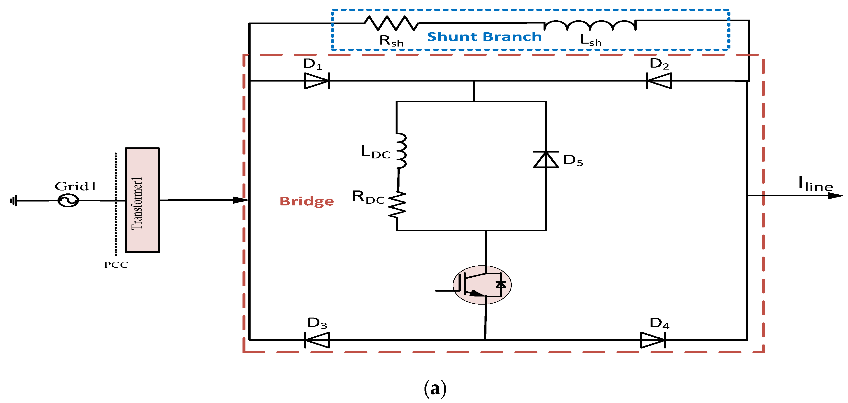
Figure 1. Bridge type fault current limiter (a) configuration (b) control strategy.
Energies 10 01898 g001aEnergies 10 01898 g001b
Figure 2. Schematic diagram of VSC-HVDC systems (a) Two grids connected mode (b) Wind farm integrated mode.
Energies 10 01898 g002
Figure 3. HVDC system controllers (a) VSC1 controller with BFCL/SDBR (b) VSC2 controller with BFCL/SDBR.
Energies 10 01898 g003
Figure 4. Real Time Digital Simulator setup.
Energies 10 01898 g004
Figure 5. Comparative transient response of two grids connected VSC-HVDC system subject to symmetrical fault at grid1 (a) DC link voltage (b) Grid1 active power flow (c) Phase ‘a’ current of grid1.
Energies 10 01898 g005aEnergies 10 01898 g005b
Figure 6. Voltage and current stresses of BFCL subject to symmetrical fault at grid1 (a) Voltage across shunt branch (b) Current through the shunt branch (c) Voltage across IGBT switch (d) Current through IGBT switch.
Energies 10 01898 g006aEnergies 10 01898 g006b
Figure 7. Comparative transient response of fixed speed wind integrated VSC-HVDC system subject to symmetrical fault at PCC (a) Induction machine speed (b) Induction machine stator current (c) DC link voltage.
Energies 10 01898 g007
Figure 8. Comparative transient response of a two grids-connected VSC-HVDC system subject to a 1LG fault at grid1 (a) DC link voltage (b) Grid1 active power flow (c) Phase ‘a’ current of grid1.
Energies 10 01898 g008aEnergies 10 01898 g008b
Figure 9. Comparative transient response of two grids connected VSC-HVDC system subject to 2LG fault at grid1 (a) DC link voltage (b) Grid1 active power flow (c) Phase ‘a’ current of grid1.
Energies 10 01898 g009aEnergies 10 01898 g009b
Table 1. HVDC system parameters.
ParameterValue
HVDC system power rating30 MVA
Grid voltage140 kV (l-l rms)
Frequency60 Hz
Transfer power rating30 MVA
Voltage ratio of the transformer140/18 kV (Delta/Y)
Leakage inductance of transformer referred to delta side110 mH
Interface resistor (R) and reactor (L) 88 mΩ and 8.5 mH
DC cable length25 km
DC cable resistance, inductance, and capacitance6 mΩ/km, 0.8 mH/km, 0.20 µF/km
DC capacitance500 µF
Reference DC bus voltage35 kV
BFCL shunt resistor and inductor10 mΩ and 2 mH
RDC and LDC of BFCL0.1 mΩ and 0.1 mH
SDBR resistor10 mΩ
Inner current controller Kpid8.5
Inner current controller Kiiq88
Outer voltage controller Kpvdc0.1036
Outer voltage controller Kivdc17.77
Feed forward function (FFF)1/(1 + 7 × 10⁻⁶ s)
Table 2. Wind system parameters.
ParameterValue
Rotor blade radius41 m
Wind speed (cut-in/nominal/cut-out)3.5/13/20 m/s
Nominal turbine speed14.4 rpm
Rated power1.65 MW
Induction machine6 pole, 1200 rpm
Induction machine speed at rated power1207 rpm
Rated slip0.00167
Gear box ratio84.5
Power factor correction capacitors499.4 kVAR
Stator resistance0.0077 Ω
Rotor resistance0.0062 Ω
Stator reactance0.0697 Ω
Magnetizing reactance3.454 Ω
Rotor reactance0.0834 Ω
Table 3. Performance index improvement with the proposed BFCL for symmetrical fault (two grids-connected VSC-HVDC system).
Index Parameters, %Values of Indices
Without FCLSDBRProposed BFCL
dcvolt3.18832.19350.35573
acpow (grid1)19.27799.56830.69532
linecurr (grid1)1.03230.731880.22665
Table 4. Performance index improvement with the proposed BFCL for a symmetrical fault (wind farm-integrated VSC-HVDC system).
Index Parameters, %Values of Indices
Without FCLSDBRProposed BFCL
dcvolt1.34560.307260.16663
MACspeed2.00752.00692.0063
linecurr (stator)1.02420.945480.8011
Table 5. Performance index improvement with the proposed BFCL for a 1LG fault (two grids-connected VSC-HVDC system).
Index Parameters, %Values of Indices
Without FCLSDBRProposed BFCL
dcvolt0.216880.177790.12088
acpow (grid1)0.110240.0694920.030914
linecurr (grid1)0.174330.171930.16587
Table 6. Performance index improvement with the proposed BFCL for a 2LG fault (two grids-connected VSC-HVDC system).
Index Parameters, %Values of Indices
Without FCLSDBRProposed BFCL
dcvolt0.614580.578930.25341
acpow (grid1)2.79372.28051.9214
linecurr (grid1)0.250320.245430.13371