A New Reactive-Power Sharing Scheme for Two Inverter-Based Distributed Generations with Unequal Line Impedances in Islanded Microgrids


Abstract
:1. Introduction
2. Proposed Droop Control
2.1. Droop Control Concept
2.2. Reactive Power Sharing
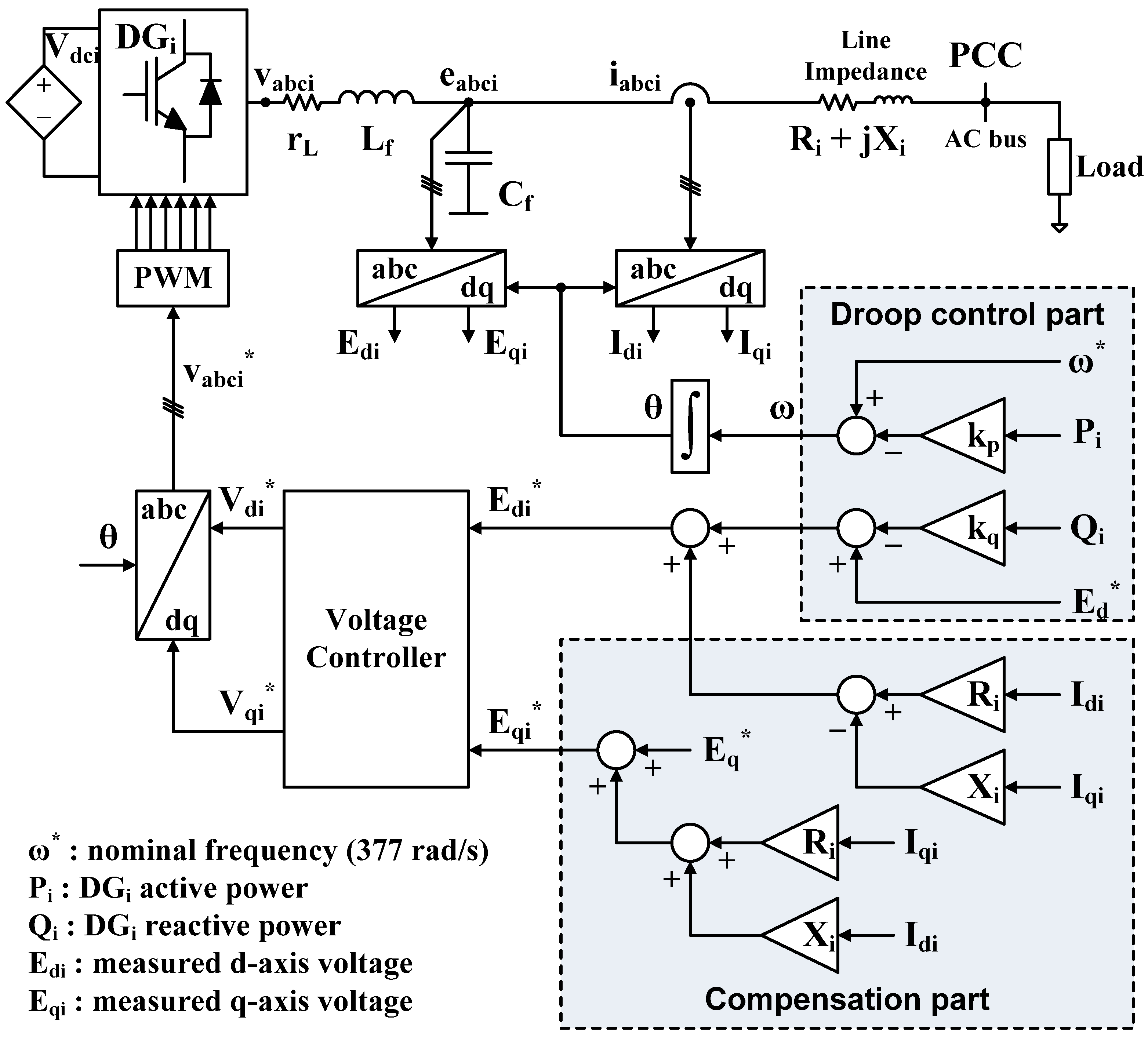
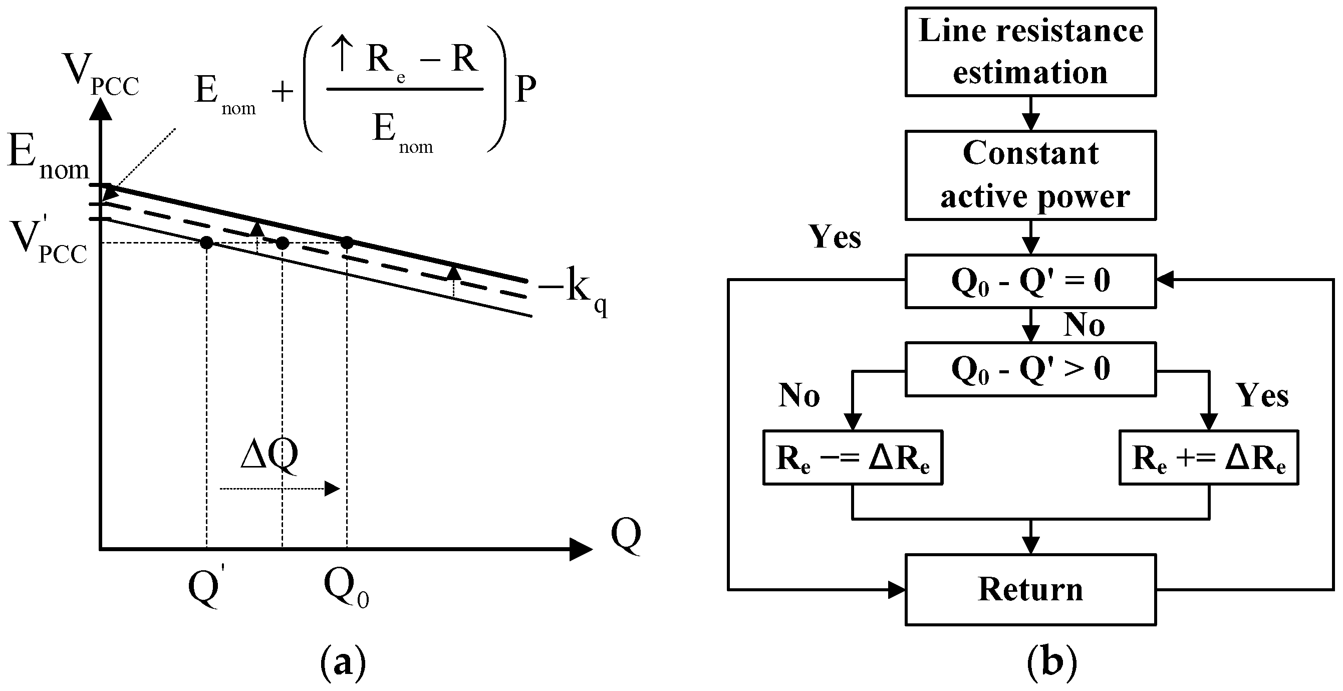
2.3. Proposed Droop Control
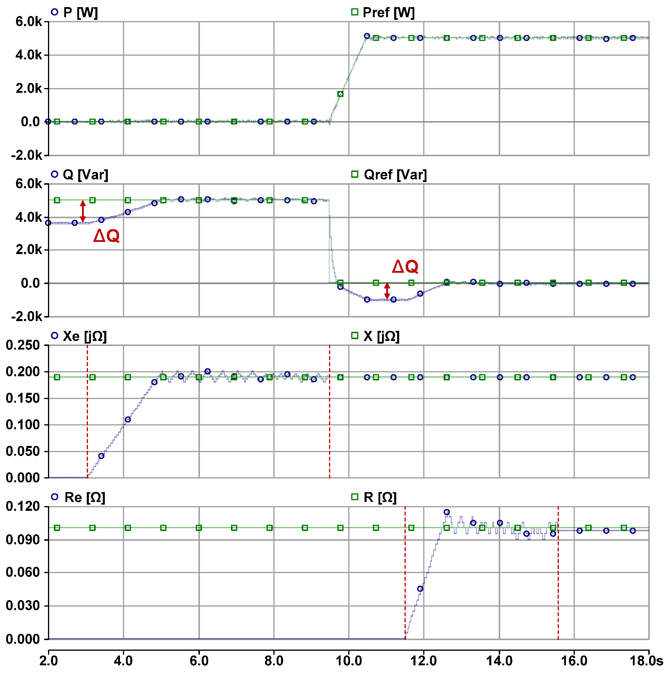
3. Line Impedance Estimation
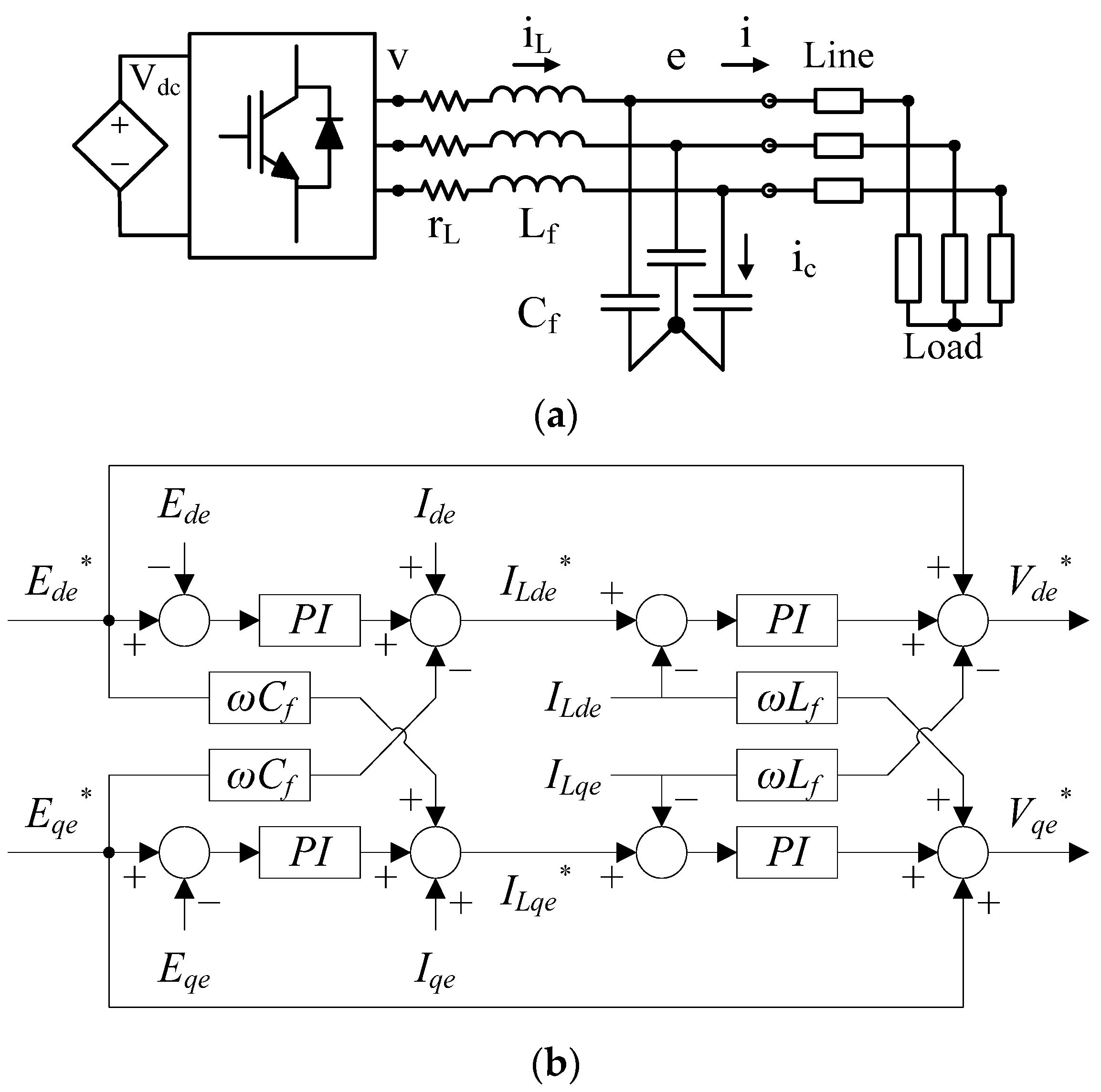
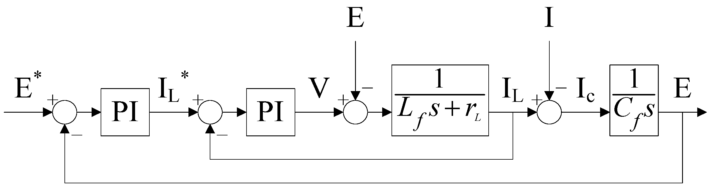
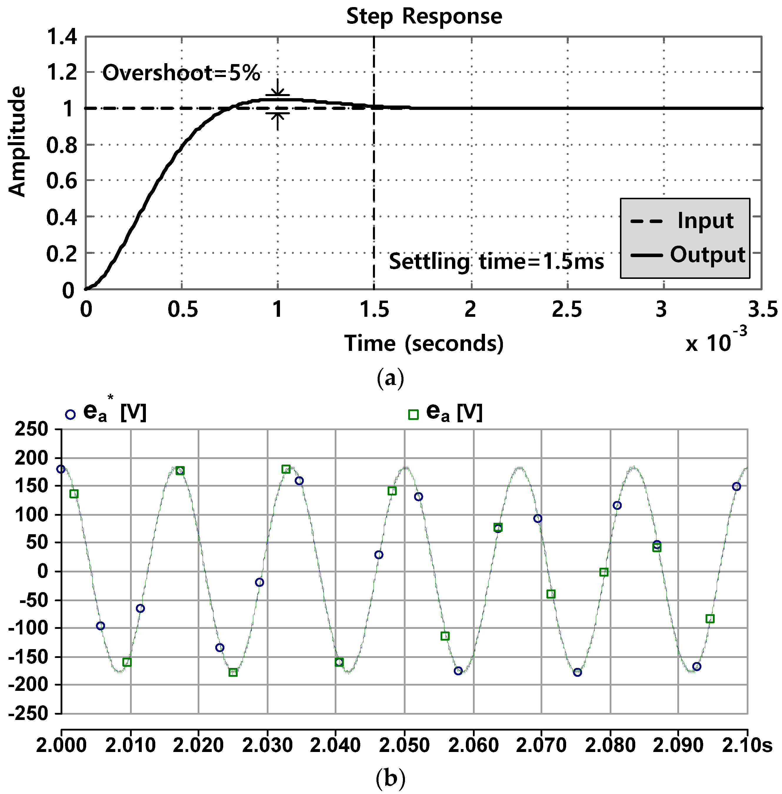
4. Voltage Control Design
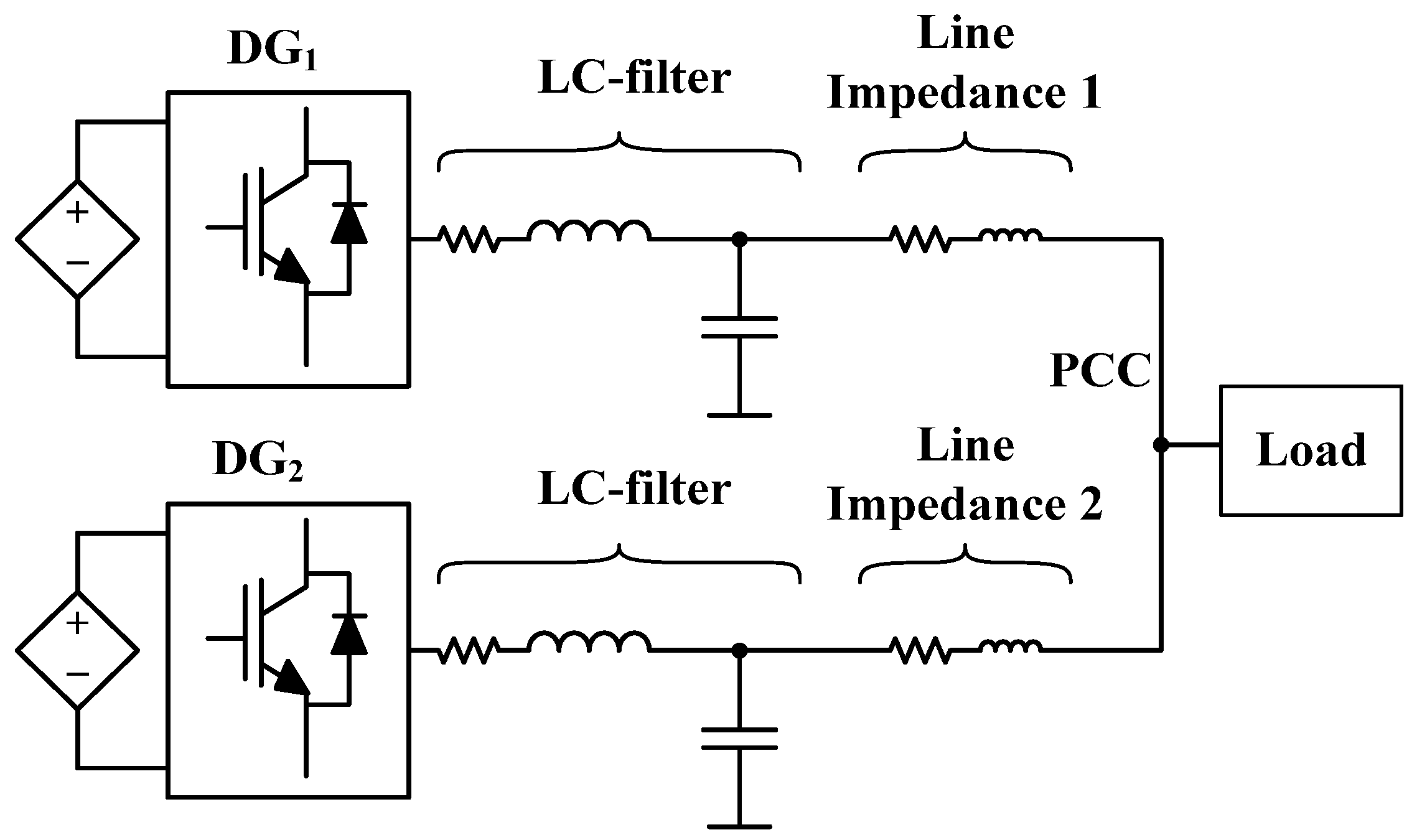
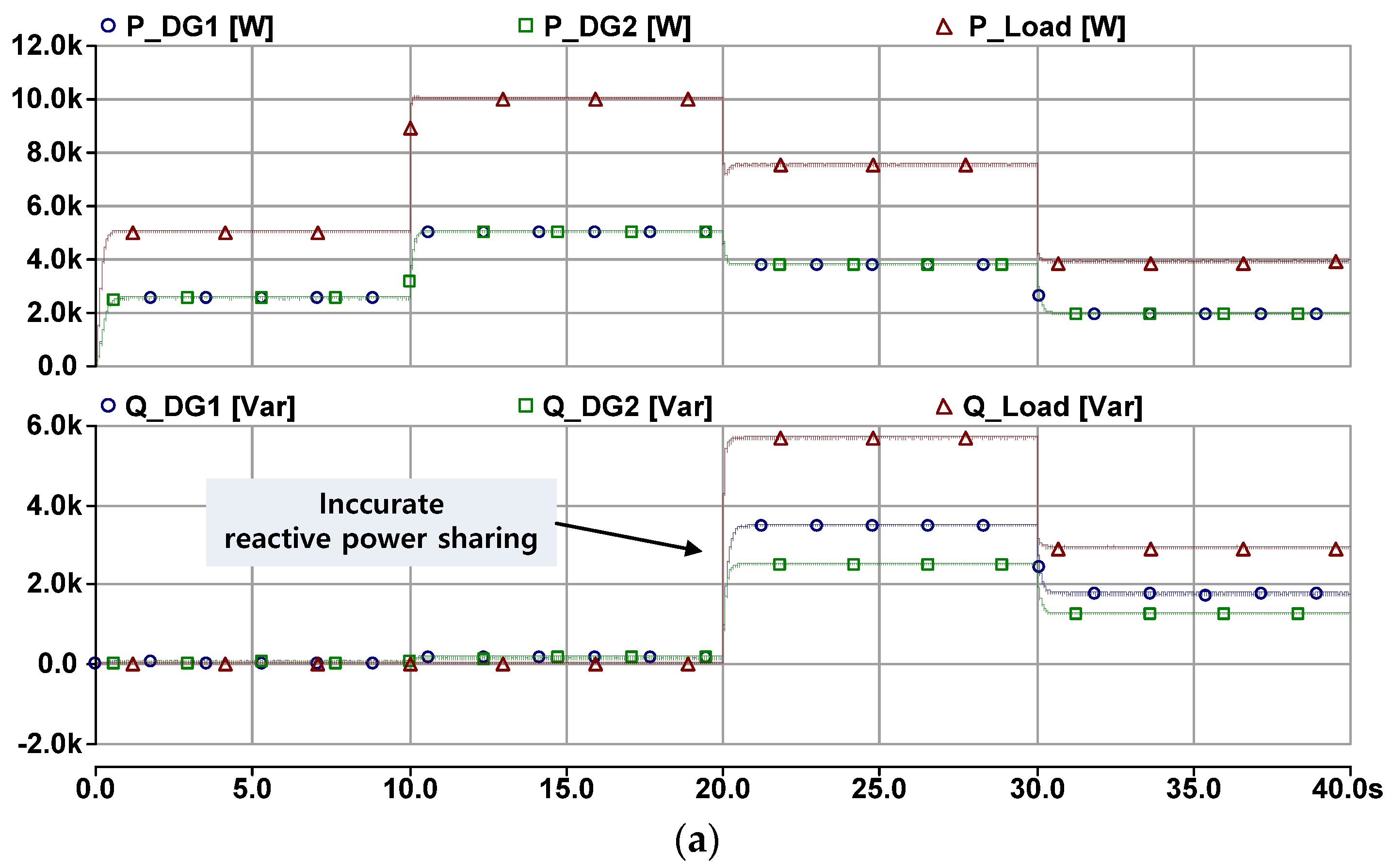
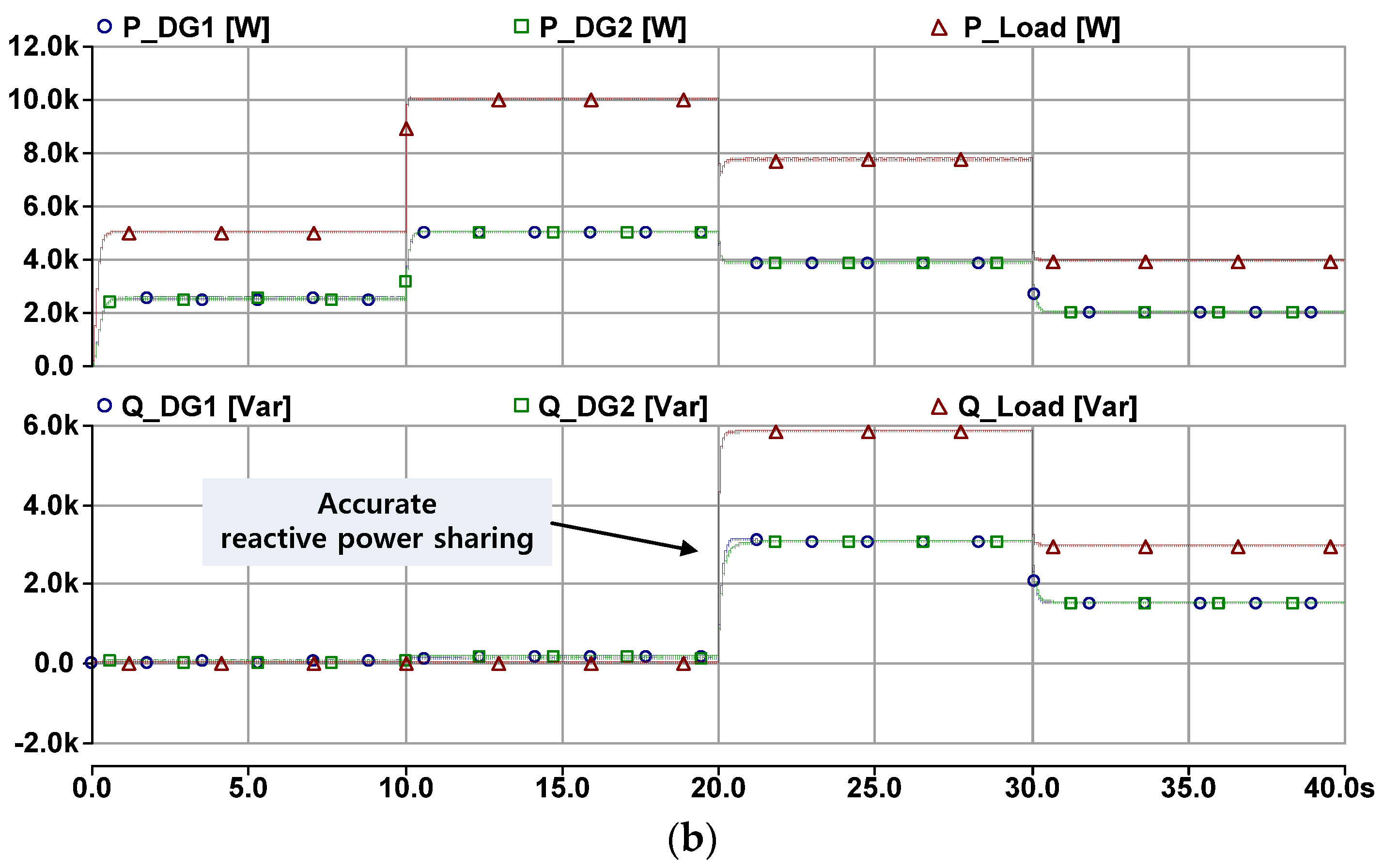
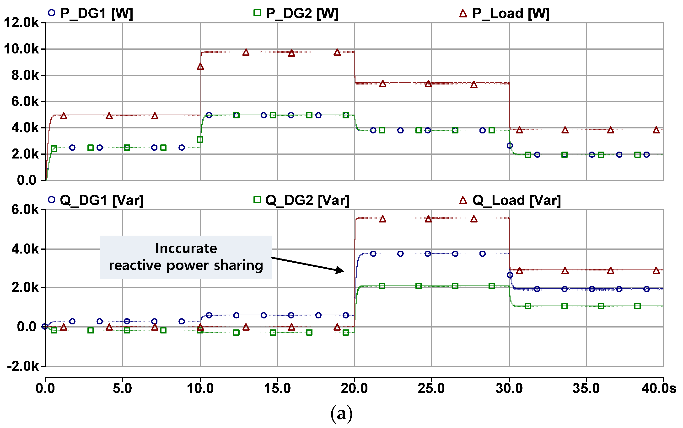
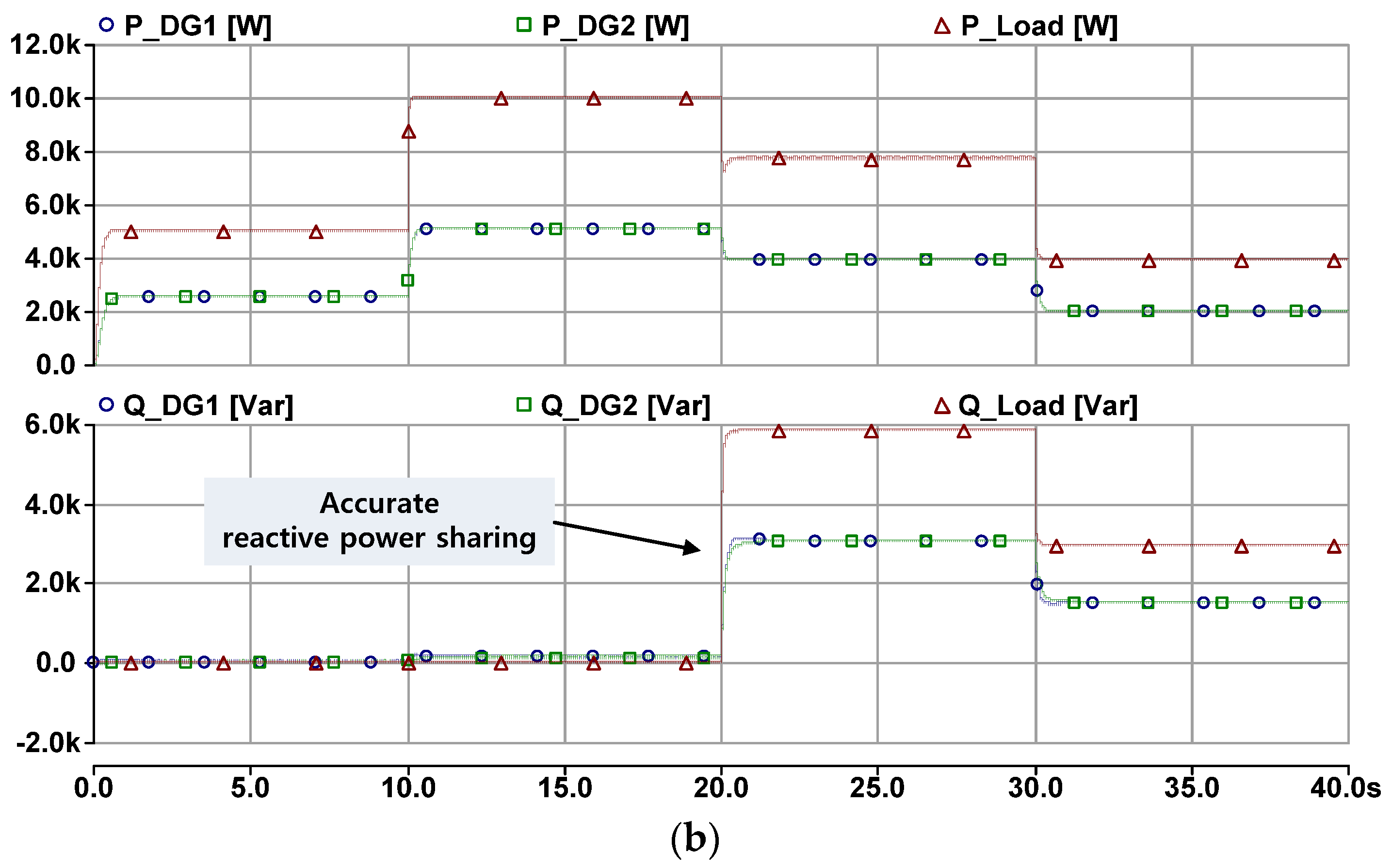
5. Computer Simulation
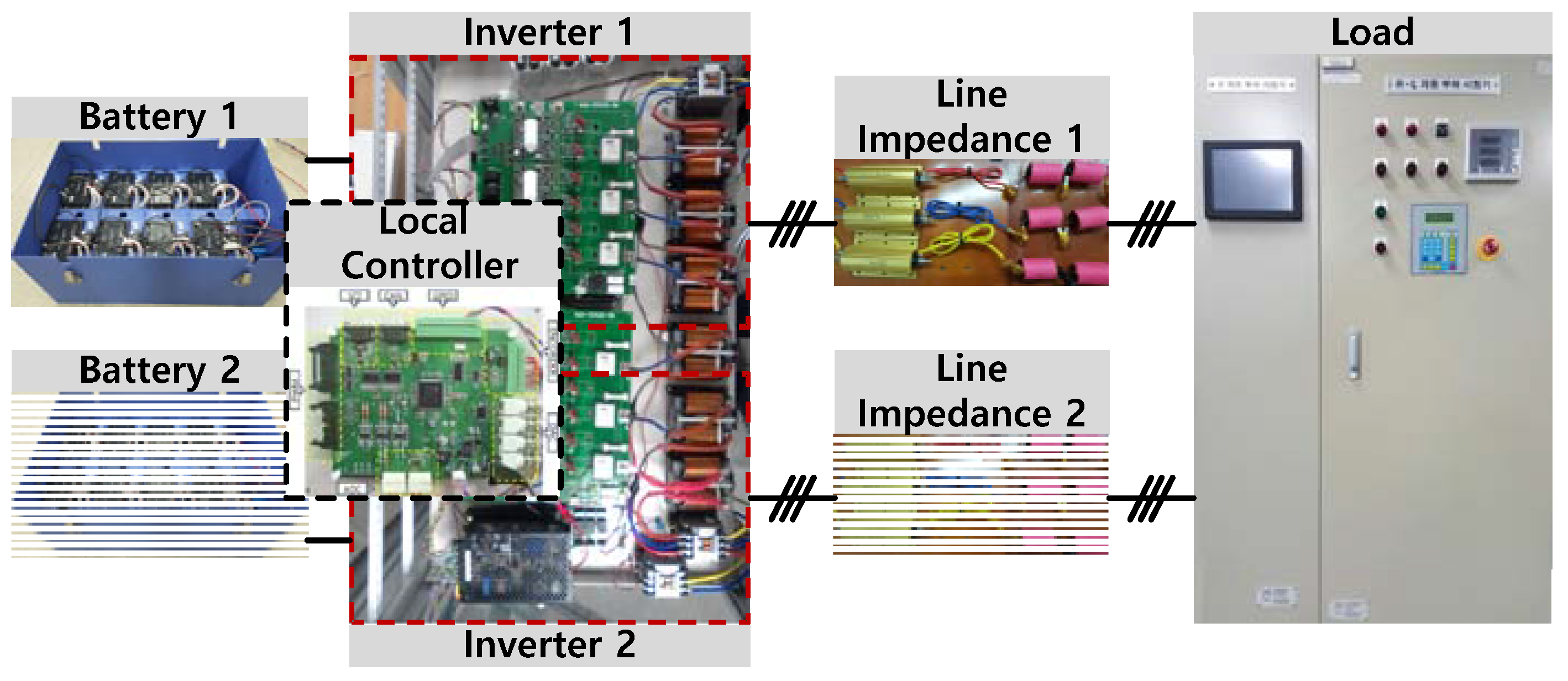
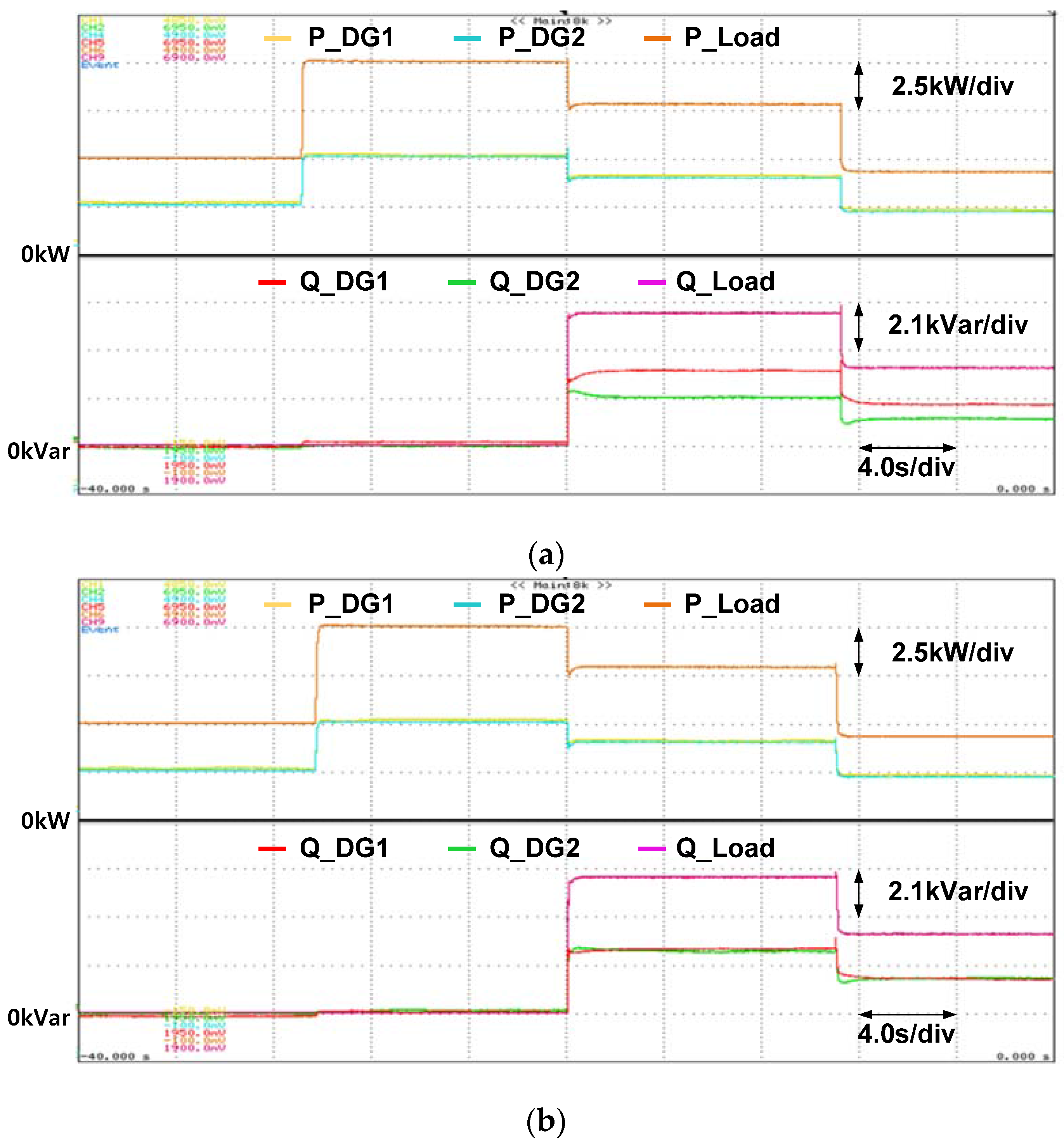
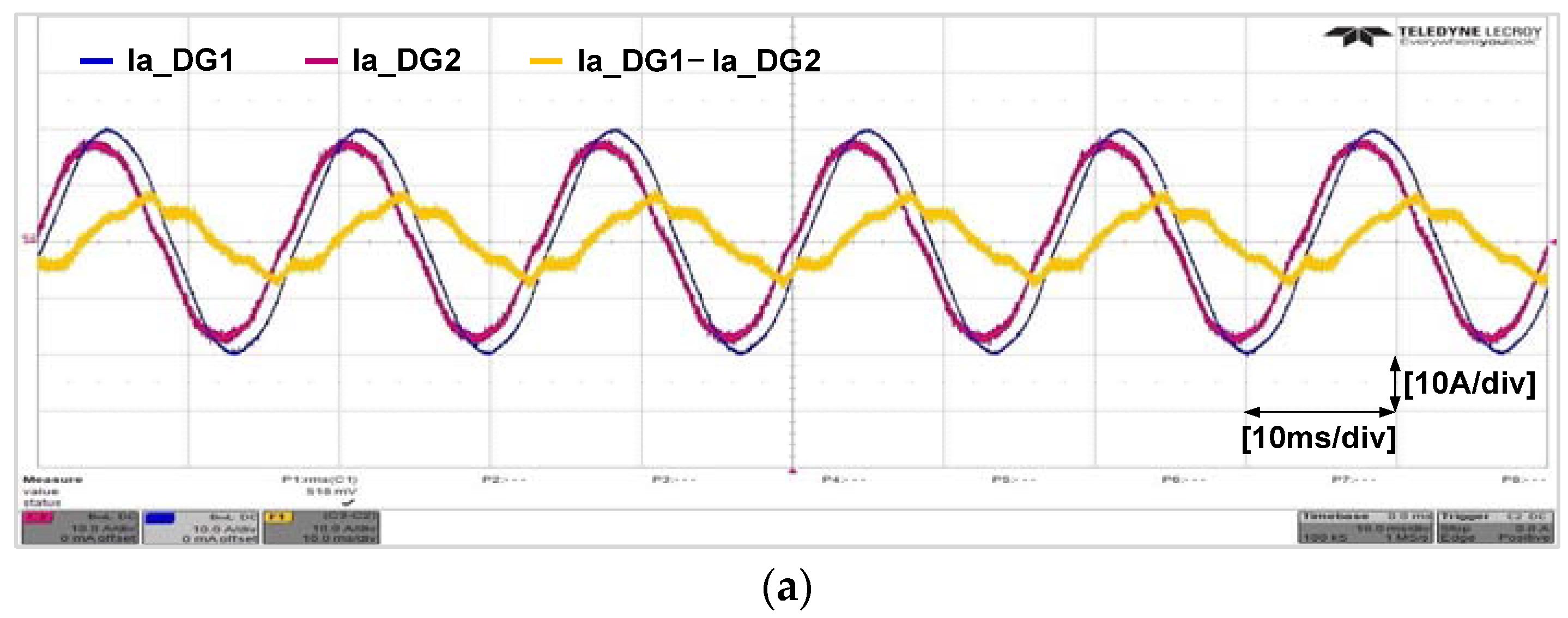
6. Experimental Verification
7. Conclusions
Acknowledgments
Author Contributions
Conflicts of Interest
Nomenclature
| Active power | |
| Reactive power | |
| Droop coefficient of frequency | |
| Droop coefficient of magnitude | |
| Nominal frequency of PCC | |
| Nominal voltage of PCC | |
| Output voltage frequency | |
| Output voltage magnitude | |
| Output voltage (d-axis) | |
| Output voltage (q-axis) | |
| Output voltage reference (d-axis) | |
| Output voltage reference (q-axis) | |
| Load voltage (d-axis) | |
| Lad voltage (q-axis) | |
| Magnitude of load voltage | |
| PCC voltage (d-axis) | |
| PCC voltage (q-axis) | |
| Magnitude of PCC voltage | |
| Magnitude of nominal voltage | |
| Output current (d-axis) | |
| Output current (q-axis) | |
| Line resistance | |
| Line reactance | |
| Estimated line resistance | |
| Estimated line reactance | |
| The number of DG () | |
| DC-link voltage of DG | |
| Output voltage of DG | |
| Output voltage without filter | |
| Output current of DG | |
| Inductor current | |
| Capacitor current | |
| Fier inductor | |
| Parasitic resistance | |
| Filter capacitor | |
| Output voltage (d-axis) | |
| Output voltage (q-axis) | |
| Output voltage reference (d-axis) | |
| Output voltage reference (q-axis) | |
| Output voltage reference (d-axis) | |
| Output voltage reference (q-axis) | |
| Output current (d-axis) | |
| Output current (q-axis) | |
| Inductor current (d-axis) | |
| Inductor current (q-axis) | |
| Compensated current(d axis) | |
| Compensated current(q axis) | |
| Proportional gain of current control | |
| Integral gain of current control | |
| Proportional gain of voltage control | |
| Integral gain of voltage control | |
| Cut-off frequency |
References
- Li, Y.W.; Kao, C.N. An accurate power control strategy for power electronics-interfaced distributed generation units operating in a low voltage Multi bus microgrid. IEEE Trans. Power Electron. 2009, 24, 2977–2988. [Google Scholar]
- Mahmud, M.; Hossain, M.; Pota, H.; Oo, A. Robust nonlinear distributed controller design for active and reactive power sharing in islanded microgrid. IEEE Trans. Energy Convers. 2014, 29, 893–903. [Google Scholar] [CrossRef]
- Souza, W.; Mendes, M.; Lopes, L. Power sharing control strategies for a three-phase microgrid in different operating condition with droop control and damping factor investigation. IET Proc. Renew. Power Gener. 2015, 9, 831–839. [Google Scholar] [CrossRef]
- Guerrero, J.; de Vicuna, L.; Matas, J.; Castilla, M.; Miret, J. A wireless controller to enhance dynamic performance of parallel inverters in distributed generation system. IEEE Trans. Power Electron. 2004, 19, 1205–1213. [Google Scholar] [CrossRef]
- Kahrobaeian, A.; Mohamed, Y.A.R.I. Networked-based hybrid distributed power sharing and control for islanded microgrid systems. IEEE Trans. Power Electron. 2015, 30, 603–617. [Google Scholar] [CrossRef]
- Shafiee, Q.; Guerrero, J.M.; Vasquez, J. Distributed secondary control for islanded microgrids—A novel approach. IEEE Trans. Power Electron. 2014, 29, 1018–1031. [Google Scholar] [CrossRef]
- Liang, H.; Choi, B.J.; Zhuang, W. Stability enhancement of decentralized inverter control through wireless communications in microgrids. IEEE Trans. Smart Grid 2013, 4, 321–331. [Google Scholar] [CrossRef]
- Mohamed, Y.; El-Saadany, E. Adaptive decentralized droop controller to preserve power sharing stability of paralleled inverters in distributed generation microgrids. IEEE Trans. Power Electron. 2008, 23, 2806–2816. [Google Scholar] [CrossRef]
- Majumder, R.; Ghosh, A.; Ledwich, G.; Zare, F. Operation and control of hybrid microgrid with angle droop controller. In Proceedings of the 2010 IEEE Region 10 Conference, Fukuoka, Japan, 21–24 November 2010; pp. 509–515. [Google Scholar]
- Chiang, H.C.; Jen, K.K.; You, G.H. Improved droop control method with precise current sharing and voltage regulation. IET Power Electron. 2016, 9, 789–800. [Google Scholar] [CrossRef]
- Hua, H.; Liu, Y.; Sun, Y.; Su, M.; Guerrero, J.M. An improved droop control strategy for reactive power sharing in islanded microgrid. IEEE Trans. Power Electron. 2015, 30, 3133–3141. [Google Scholar]
- Brabandere, K.D.; Bolsens, B.; Keybus, J.V.D.; Woyte, A.; Driesen, J.; Belmans, R. A voltage and frequency droop control method for parallel inverters. IEEE Trans. Power Electron. 2007, 22, 1107–1115. [Google Scholar] [CrossRef]
- Han, Y.; Li, H.; Shen, P.; Coelho, E.; Guerrero, J. Review of Active and Reactive Power Sharing Strategies in Hierarchical Controlled Microgrids. IEEE Trans. Power Electron. 2017, 32, 2427–2451. [Google Scholar] [CrossRef]
- Mahmood, H.; Michaelson, D.; Jiang, J. Reactive power sharing in islanded microgrids using adaptive voltage droop control. IEEE Trans. Smart Grid 2015, 6, 3052–3060. [Google Scholar] [CrossRef]
- He, J.W.; Li, Y.W. An enhanced microgrid load demand sharing strategy. IEEE Trans. Power Electron. 2012, 27, 3984–3995. [Google Scholar] [CrossRef]
- Li, P.; Wang, X.B.; Lee, W.J.; Xu, D. Dynamic power conditioning method of microgrid via adaptive inverse control. IEEE Trans. Power Deliv. 2015, 30, 906–913. [Google Scholar] [CrossRef]
- Yao, W.; Chen, M.; Matas, J.; Guerrero, J.M.; Qian, Z.M. Design and analysis of the droop control method for parallel inverters considering the impact of the complex impedance on the power sharing. IEEE Trans. Ind. Electron. 2011, 58, 576–588. [Google Scholar] [CrossRef]
- Zhong, Q. Robust Droop Controller for Accurate Proportional Load Sharing among Inverters Operated in Parallel. IEEE Trans. Ind. Electron. 2013, 60, 1281–1290. [Google Scholar] [CrossRef]
- You, Z.; Liu, J.; Zhang, X.; Wang, X. A Decoupled and Adaptive Power Sharing Strategy Based on Droop Method for Parallel Inverters. In Proceedings of the APEC 2014, Fort Worth, TX, USA, 16–20 March 2014. [Google Scholar]
- Lee, C.; Chu, C.; Cheng, P. A New Droop Control Method for the Autonomous Operation of Distributed Energy Resource Interface Converters. IEEE Trans. Power Electron. 2013, 28, 1980–1993. [Google Scholar] [CrossRef]
- Guerrero, J.; Matas, J.; de Vicuna, L.; Castila, M.; Miret, J. Decentralized control for parallel operation of distributed generation inverters using resistive impedance. IEEE Trans. Ind. Electron. 2007, 54, 994–1004. [Google Scholar] [CrossRef]
- He, J.W.; Li, Y.W. Analysis, Design, and Implementation of Virtual Impedance for Power Electronics Interfaced Distributed Generation. IEEE Trans. Ind. Appl. 2011, 47, 2525–2538. [Google Scholar] [CrossRef]
- Mahmood, H.; Michaelson, D.; Jiang, J. Accurate reactive power sharing in an islanded microgrid using adaptive virtual impedance. IEEE Trans. Power Electron. 2015, 30, 1605–1617. [Google Scholar] [CrossRef]
- Guo, Q.; Wu, H.; Lin, L.; Bai, Z.; Ma, H. Secondary Voltage Control for Reactive Power Sharing in an Islanded Microgrid. J. Power Electron. 2016, 16, 329–339. [Google Scholar] [CrossRef]
- Tuladhar, A.; Jin, H.; Unger, T.; Mauch, K. Control of parallel inverters in distributed AC power systems with consideration of line impedance effect. IEEE Trans. Ind. Appl. 2000, 36, 131–138. [Google Scholar] [CrossRef]
- Zhang, X.; Liu, J.; You, Z.; Liu, T. Study on the Influence of Distributed Lines to Parallel Inverter Systems Adopting the Droop Control Method. J. Power Electron. 2013, 13, 701–711. [Google Scholar] [CrossRef]
- Sumner, M. Impedance measurement for improved power quality—Part 1: The measurement technique. IEEE Trans. Power Deliv. 2004, 19, 1442–1448. [Google Scholar] [CrossRef]
- Roinila, T.; Vilkko, M.; Sun, J. Broadband methods for on-line grid impedance measurement. In Proceedings of the IEEE Energy Conversion Congress & Exposition (ECCE 2013), Denver, CO, USA, 15–19 September 2013; pp. 3003–3010. [Google Scholar]
- Hoffmann, N.; Fuchs, F. Minimal Invasive Equivalent Grid Impedance Estimation in Inductive-Resistive Power Networks using Extended Kalman Filter. IEEE Trans. Power Electron. 2014, 29, 631–641. [Google Scholar] [CrossRef]
- Shi, Y.; Su, J.; Li, J.; Hao, X. Line Impedance Measure Method for Microgrid. In Proceedings of the International Power Electronics and Application Conference and Exposition, Shanghai, China, 5–8 November 2014; pp. 378–383. [Google Scholar]
- Han, B.; Bae, B.; Kim, H.; Baek, S. Combined operation of unified power-quality conditioner with distributed generation. IEEE Trans. Power Deliv. 2006, 21, 330–338. [Google Scholar] [CrossRef]


| Parameter | Actual Value | Estimated Value | Error [%] |
|---|---|---|---|
| Resistance | 0.1 (Ω) | 0.0975 (Ω) | 2.5 |
| Reactance | 0.1885 (jΩ) | 0.1880 (jΩ) | 0.26 |
| Items | DG1,2 |
|---|---|
| Rated power | 5 (kVA) |
| Frequency droop coefficient | 0.0008 |
| Voltage droop coefficient | 0.001 |
| DC link (lithium-polymer battery) | 336~470.4 (V) |
| PCC voltage | 220 Vrms |
| Filter | 1 (mH) |
| Filter | 20 (uF) |
| Case 1 | Line Impedance 1 | 0.0 + j0.1885 (Ω) |
| Line Impedance 2 | 0.0 + j0.3770 (Ω) | |
| Case 2 | Line Impedance 1 | 0.1 + j0.1885 (Ω) |
| Line Impedance 2 | 0.2 + j0.3770 (Ω) |
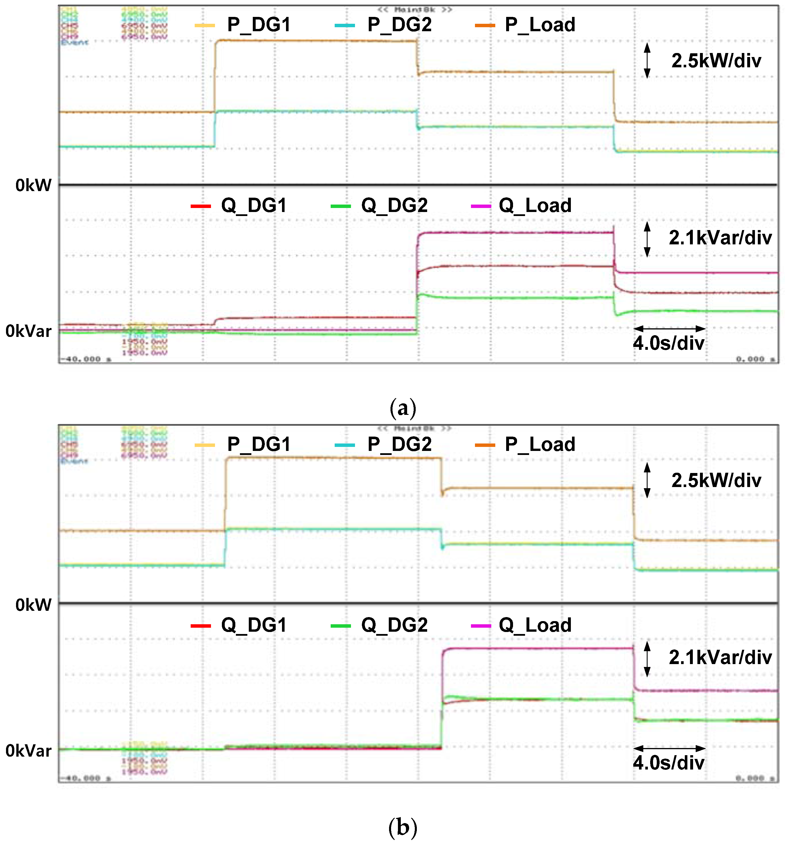
| 0–10 s | 10–20 s | 20–30 s | 30–40 s | |
|---|---|---|---|---|
| PL [kW] | 5 | 10 | 8 | 4 |
| QL [kVar] | 0 | 0 | 6 | 3 |
© 2017 by the authors. Licensee MDPI, Basel, Switzerland. This article is an open access article distributed under the terms and conditions of the Creative Commons Attribution (CC BY) license (http://creativecommons.org/licenses/by/4.0/).
Share and Cite
Kim, J.-H.; Lee, Y.-S.; Kim, H.-J.; Han, B.-M. A New Reactive-Power Sharing Scheme for Two Inverter-Based Distributed Generations with Unequal Line Impedances in Islanded Microgrids. Energies 2017, 10, 1800. https://doi.org/10.3390/en10111800
Kim J-H, Lee Y-S, Kim H-J, Han B-M. A New Reactive-Power Sharing Scheme for Two Inverter-Based Distributed Generations with Unequal Line Impedances in Islanded Microgrids. Energies. 2017; 10(11):1800. https://doi.org/10.3390/en10111800
Chicago/Turabian StyleKim, Jae-Hyuk, Yoon-Seok Lee, Hyun-Jun Kim, and Byung-Moon Han. 2017. "A New Reactive-Power Sharing Scheme for Two Inverter-Based Distributed Generations with Unequal Line Impedances in Islanded Microgrids" Energies 10, no. 11: 1800. https://doi.org/10.3390/en10111800
APA StyleKim, J.-H., Lee, Y.-S., Kim, H.-J., & Han, B.-M. (2017). A New Reactive-Power Sharing Scheme for Two Inverter-Based Distributed Generations with Unequal Line Impedances in Islanded Microgrids. Energies, 10(11), 1800. https://doi.org/10.3390/en10111800