Interlink Converter with Linear Quadratic Regulator Based Current Control for Hybrid AC/DC Microgrid


Abstract
:1. Introduction
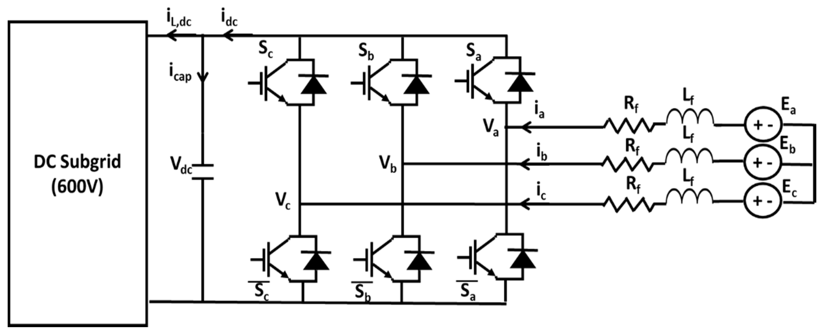
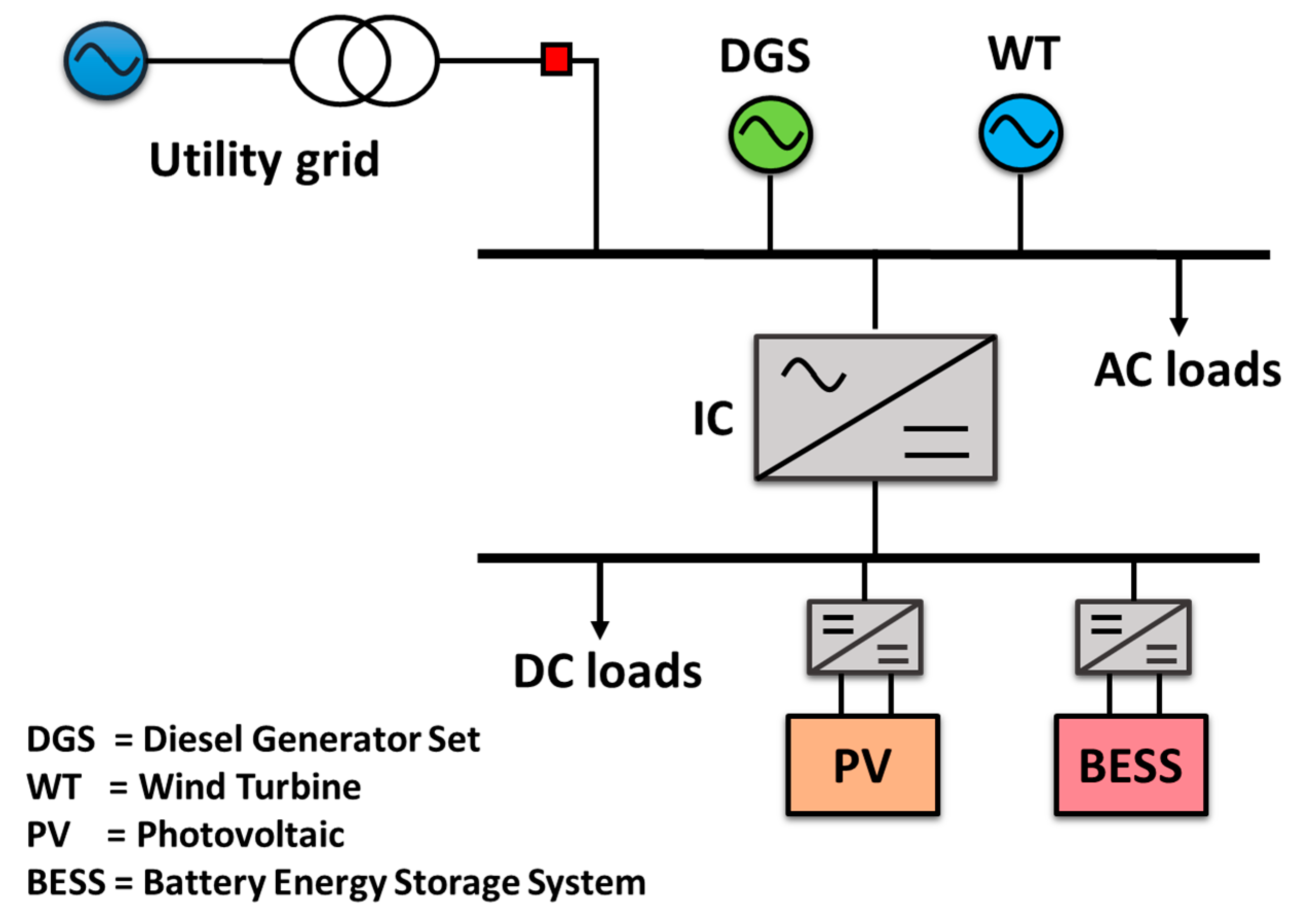
2. Hybrid AC/DC Microgrid Operation
3. Droop Control Strategy for Individual Subgrids
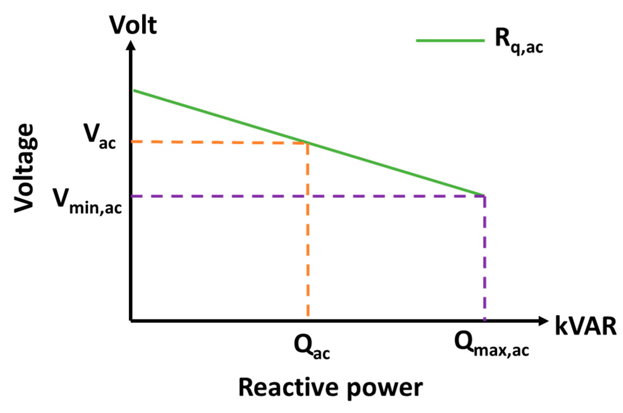
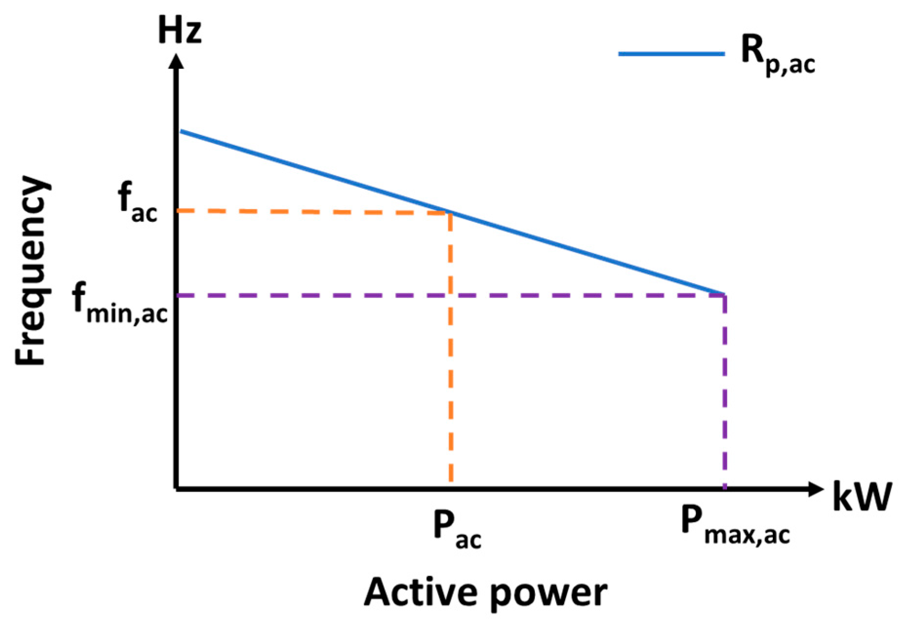
3.1. Droop Control of AC Microgrid
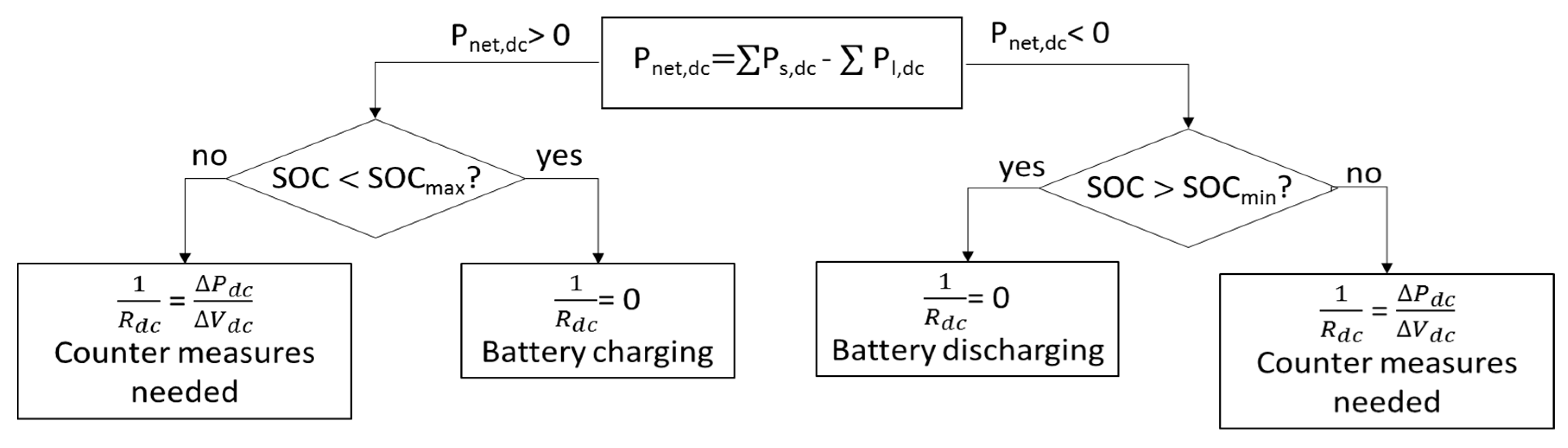
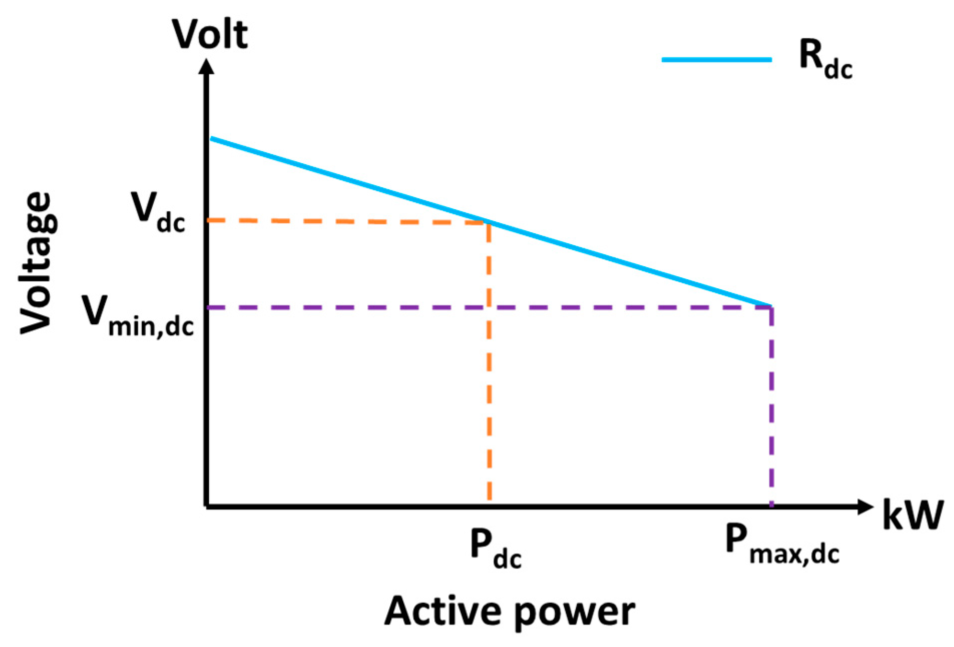
3.2. Droop Control of the DC Microgrid
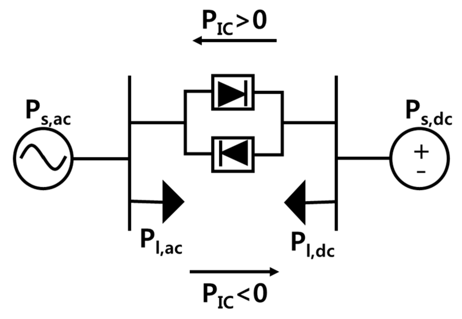
4. IC Control Strategy
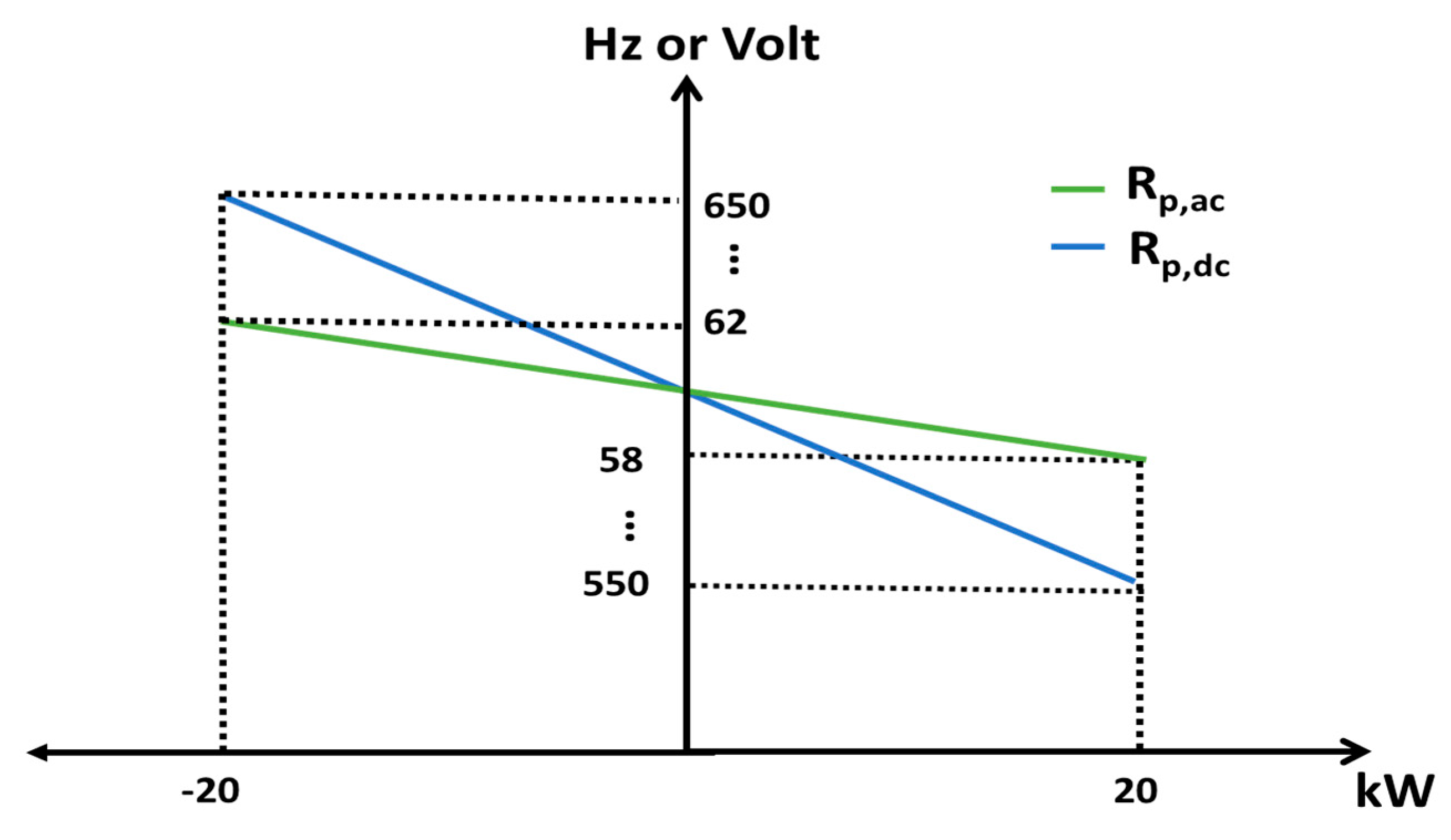
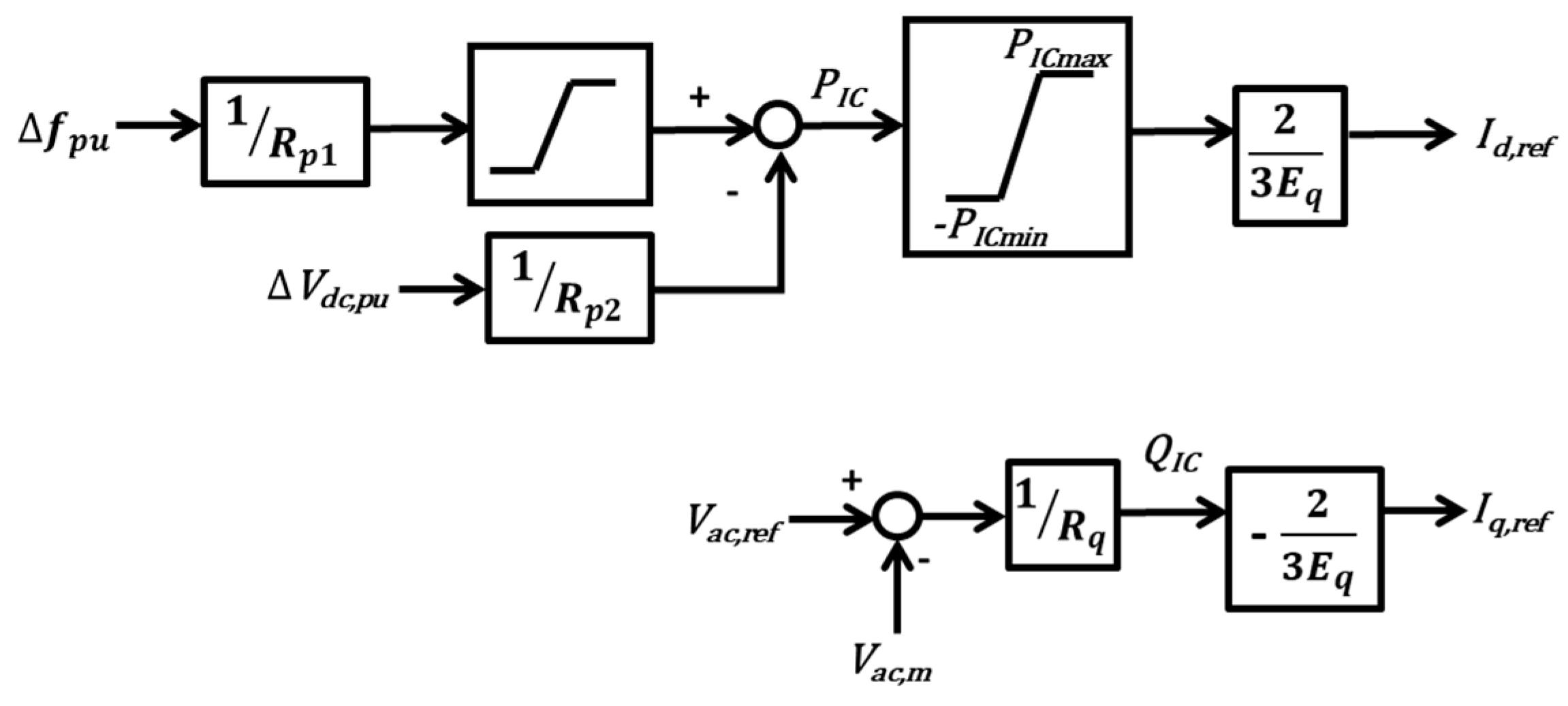
4.1. Droop Control Strategy in Hybrid AC/DC Microgrid
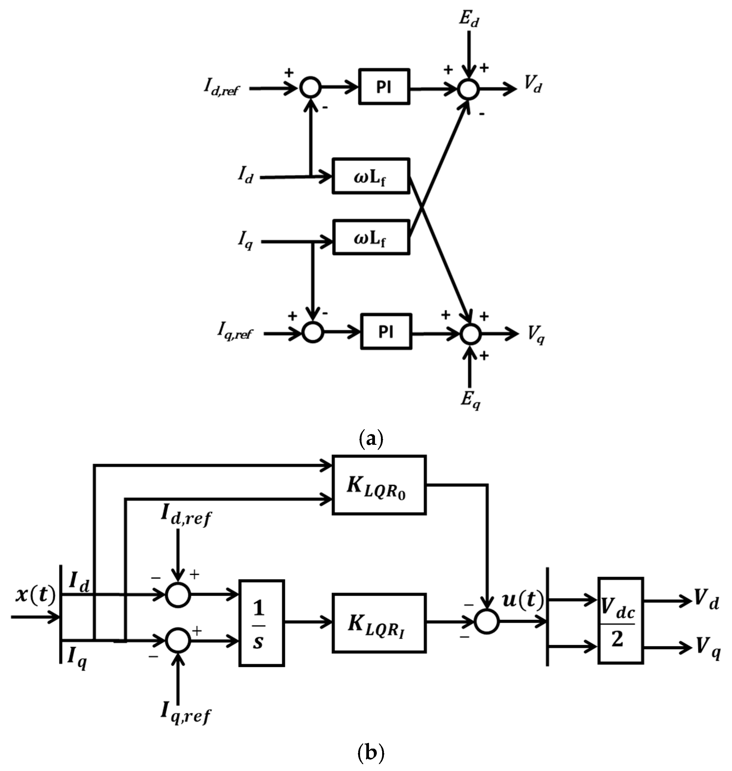
4.2. Optimized IC Current Control Using LQR
5. Results and Discussion
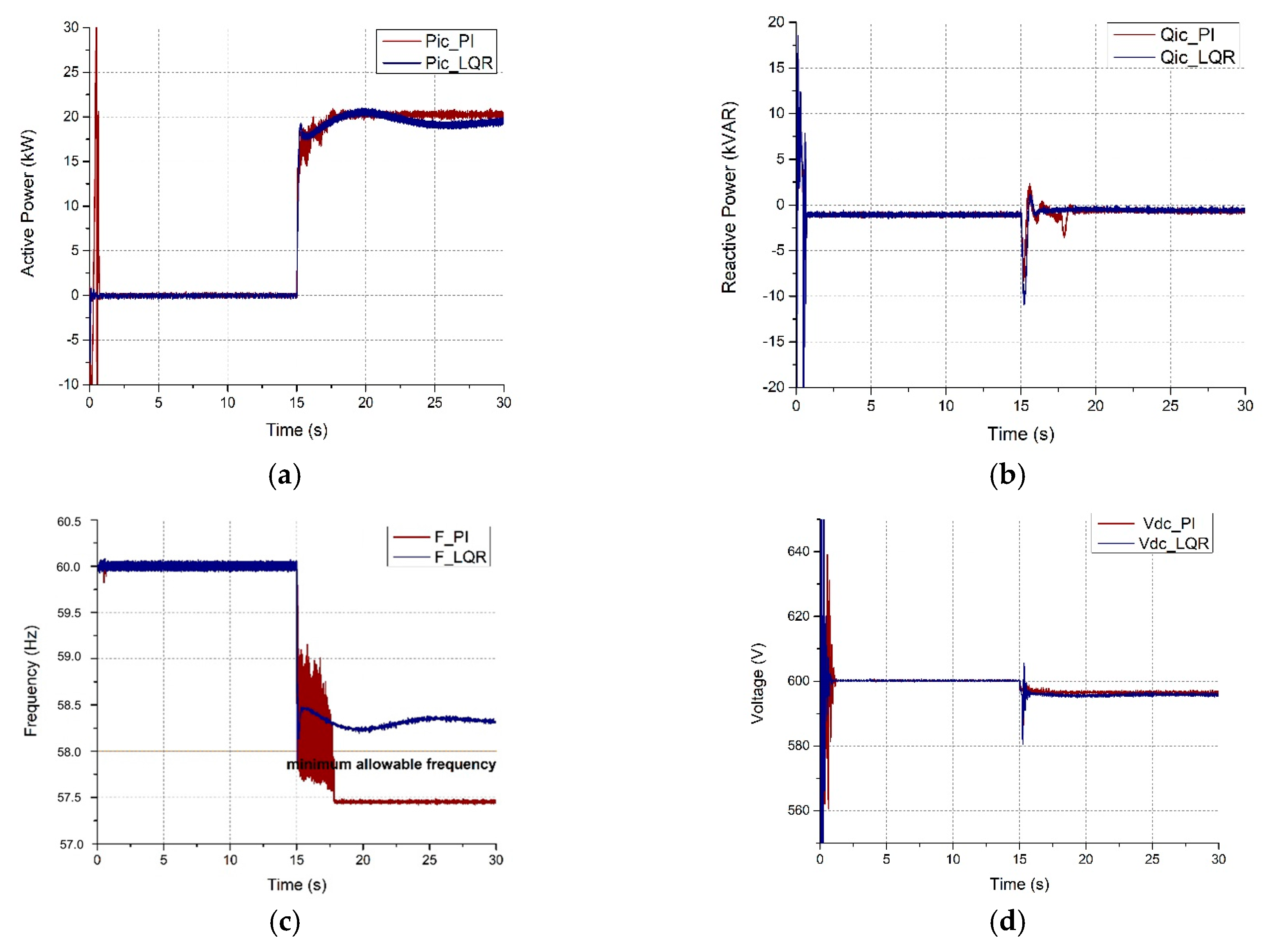
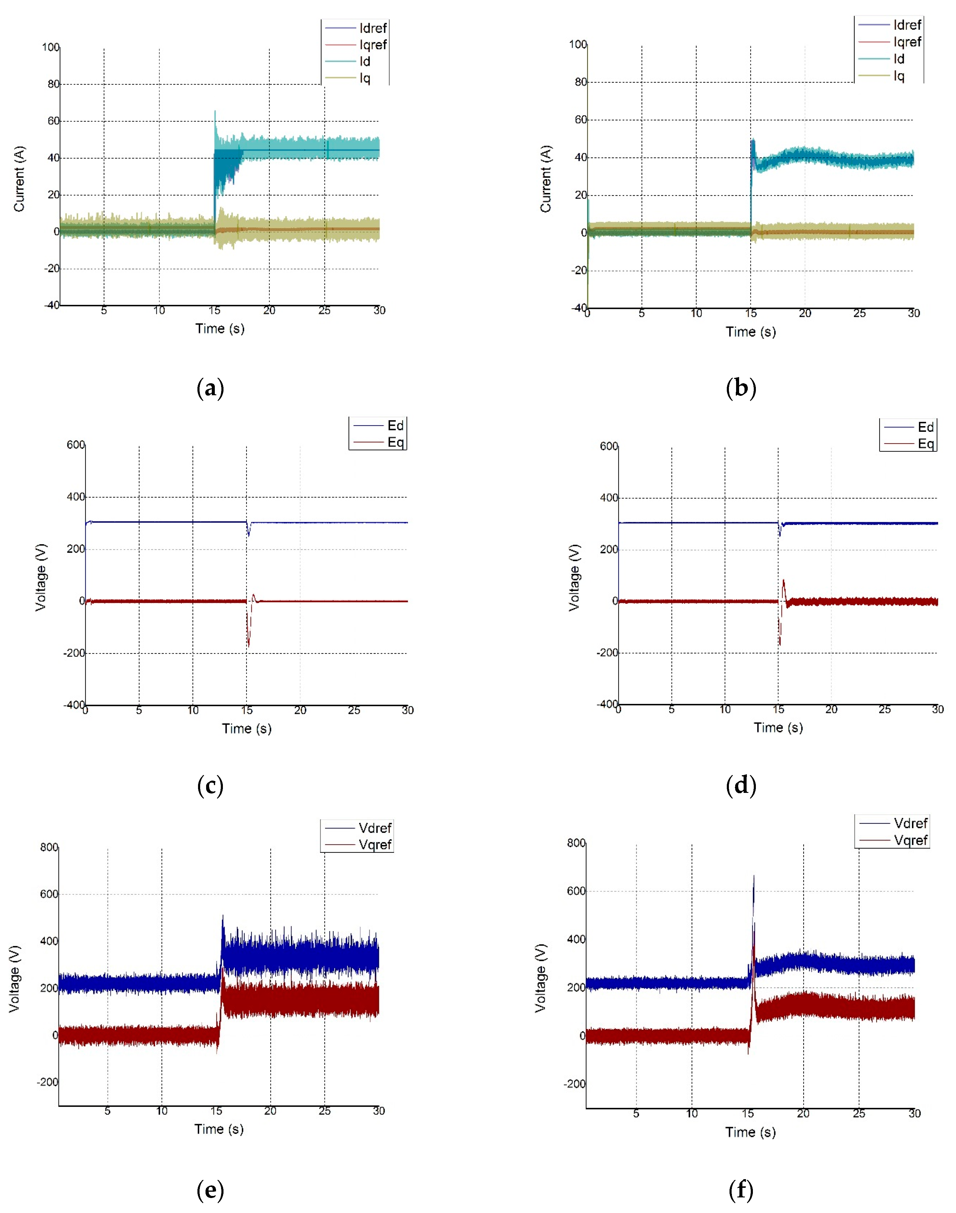
5.1. Operation Mode Transition from Grid-Connected to Stand-Alone Hybrid Microgrid
5.2. AC Load Increase with Battery Support
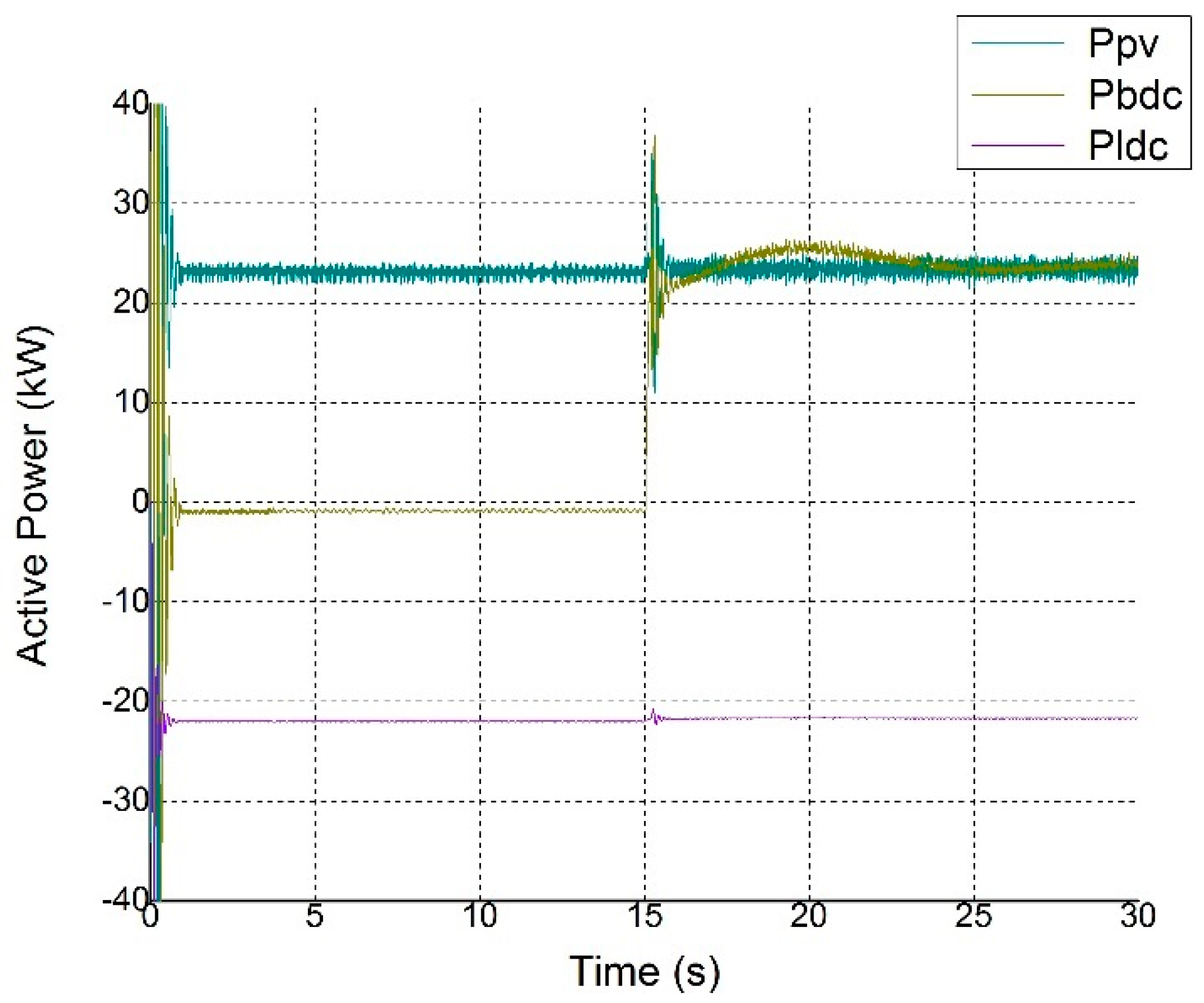
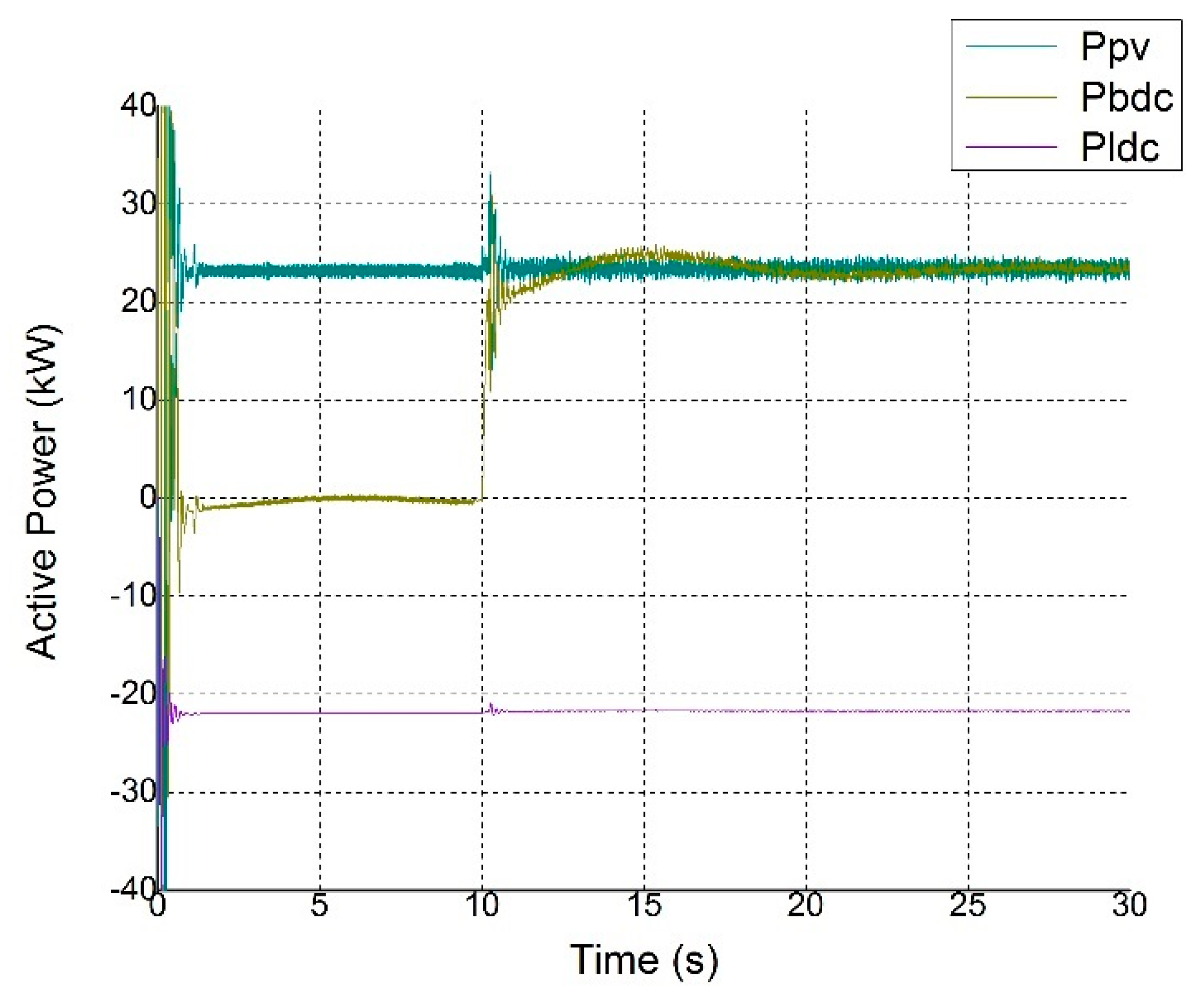
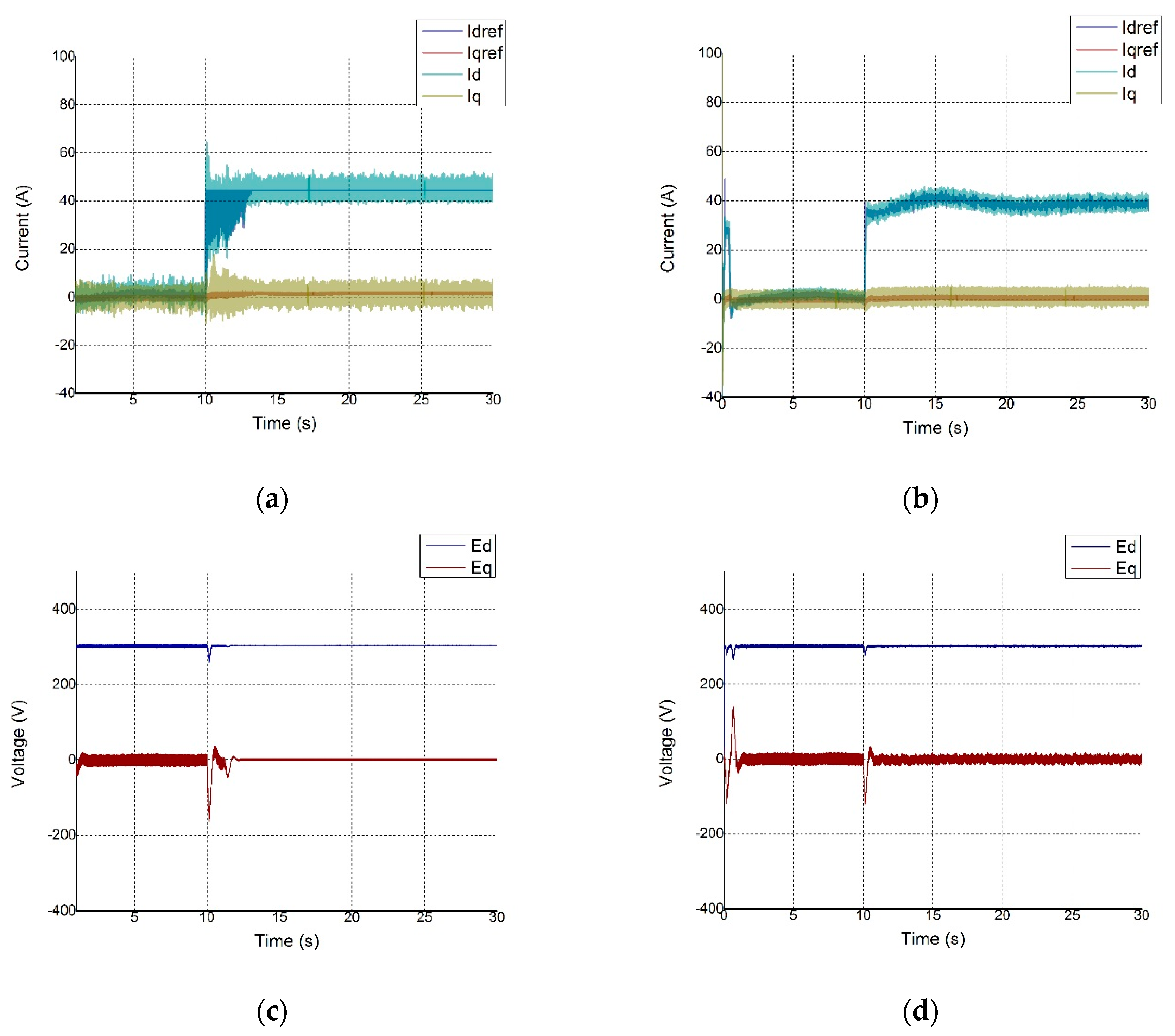
5.3. DC Load Increase without Battery Support
6. Conclusions
Acknowledgments
Author Contributions
Conflicts of Interest
Nomenclature
| frequency deviation on the AC subgrid | |
| active power deviation on the DC subgrid | |
| bus voltage deviation on the DC subgrid | |
| grid angular frequency | |
| DC link capacitance | |
| AC subgrid voltage magnitude | |
| three phase voltage at AC subgrid | |
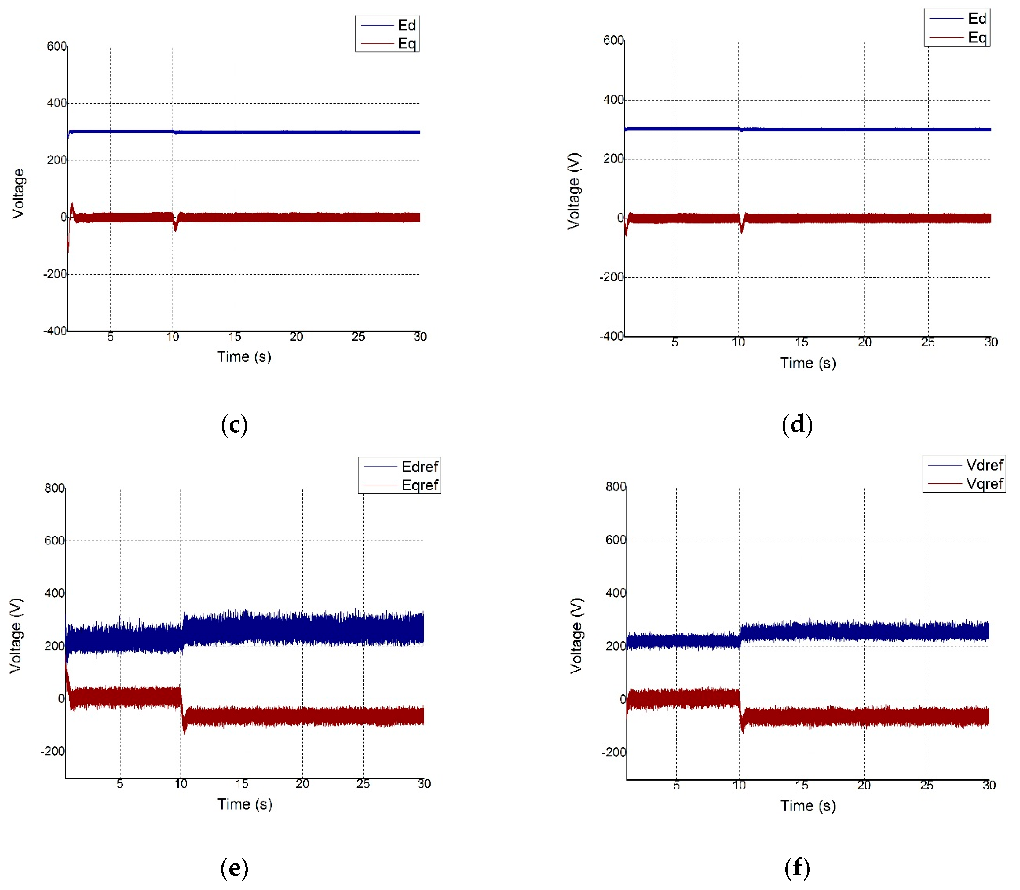
| d-axis AC subgrid voltage | |
| q-axis AC subgrid voltage | |
| AC microgrid frequency | |
| measured frequency in AC subgrid | |
| maximum allowable frequency in AC subgrid | |
| minimum allowable frequency in AC subgrid | |
| minimum allowable frequency in AC microgrid | |
| reference of frequency in AC subgrid | |
| current at AC side of IC | |
| d-axis current at AC side of IC | |
| reference of d-axis current at AC side of IC | |
| current at DC side of IC | |
| inductor current at DC side of IC | |
| q-axis current at AC side of IC | |
| reference of q-axis current at AC side of IC | |
| filter inductance | |
| gating signal of IC represented in three phase form | |
| gating signal of IC represented in d-q axis | |
| active power generated by the droop control in AC microgrid | |
| active power generated by the droop control in DC microgrid | |
| active power reference of IC | |
| active power of DC load | |
| maximum active power of the AC droop control scheme | |
| maximum active power of the DC droop control scheme | |
| net active power in DC subgrid | |
| active power of DC source | |
| reactive power produced by the droop control in AC microgrid | |
| reactive power reference of IC | |
| maximum reactive power of the AC droop control scheme | |
| voltage-active power droop characteristic in DC microgrid | |
| filter resistance | |
| frequency-active power droop characteristic in AC microgrid | |
| Frequency-active power droop characteristic of IC | |
| DC voltage-active power droop characteristic of IC | |
| AC voltage-reactive power droop characteristic of IC | |
| voltage-reactive power droop characteristic in AC microgrid | |
| voltage at AC side of IC | |
| measured AC voltage in AC microgrid | |
| measured voltage in AC subgrid | |
| reference voltage in AC subgrid | |
| d-axis voltage reference at AC side of IC | |
| measured voltage in DC microgrid | |
| measured voltage in DC subgrid | |
| maximum allowable voltage in DC subgrid | |
| minimum allowable voltage in DC subgrid | |
| reference of voltage in DC subgrid | |
| minimum allowable voltage in AC microgrid | |
| minimum allowable voltage in DC microgrid | |
| q-axis voltage reference at AC side of IC |
References
- Hatziargyriou, N. The Microgrid Concepts. In Microgrids Architectures and Control; Wiley: Chichester, UK, 2004; pp. 3–6. [Google Scholar]
- Karavas, C.S.; Kyriakarakos, G.; Arvanitis, K.G.; Papadakis, G. A multi-agent decentralized energy management system based on distributed intelligence for the design and control of autonomous polygeneration microgrids. Energy Convers. Manag. 2015, 103, 166–179. [Google Scholar] [CrossRef]
- Kuznetsova, E.; Li, Y.F.; Ruiz, C.; Zio, E. An integrated framework of agent-based modelling and robust optimization for microgrid energy management. Appl. Energy 2014, 129, 70–88. [Google Scholar] [CrossRef]
- Raju, E.S.N.; Jain, T. Hybrid AC/DC Microgrid: An Overview. In Proceedings of the Fifth International Conference on Power and Energy Systems, Kathmandu, Nepal, 28–30 October 2013. [Google Scholar]
- Nejabatkhah, F.; Li, Y.W. Overview of Power Management Strategies of Hybrid AC/DC Microgrid. IEEE Trans. Power Electron. 2015, 30, 7072–7089. [Google Scholar] [CrossRef]
- Eajal, A.A.; El-Saadany, E.F.; Ponnambalam, K. Optimal power flow for converter-dominated AC/DC hybrid microgrids. In Proceedings of the 2017 IEEE International Conference on Industrial Technology (ICIT), Toronto, ON, Canada, 22–25 March 2017; pp. 603–608. [Google Scholar]
- Tedesco, F.; Mariam, L.; Basu, M.; Casavola, A.; Conlon, M.F. Economic model predictive control-based strategies for cost-effective supervision of community microgrids considering battery lifetime. IEEE J. Emerg. Sel. Top. Power Electron. 2015, 3, 1067–1077. [Google Scholar] [CrossRef]
- Lu, X.; Guerrero, J.M.; Sun, K.; Vasquez, J.C.; Teodorescu, R.; Huang, L. Hierarchical Control of Parallel AC-DC Converter Interfaces for Hybrid Microgrids. IEEE Trans. Smart Grid 2014, 5, 683–692. [Google Scholar] [CrossRef]
- Guerrero, J.M.; Vasquez, J.C.; Matas, J.; de Vicuna, L.G.; Castilla, M. Hierarchical Control of Droop-Controlled AC and DC Microgrids—A General Approach toward Standardization. IEEE Trans. Ind. Electron. 2011, 58, 158–172. [Google Scholar] [CrossRef]
- Eghtedarpour, N.; Farjah, E. Power Control and Management in a Hybrid AC/DC Microgrid. IEEE Trans. Smart Grid 2014, 5, 1494–1505. [Google Scholar] [CrossRef]
- Loh, P.C.; Li, D.; Chai, Y.K.; Blaabjerg, F. Autonomous Operation of Hybrid Microgrid with AC and DC Subgrids. IEEE Trans. Power Electron. 2013, 28, 2214–2223. [Google Scholar] [CrossRef]
- Aryani, D.R.; Song, H. Coordination Control Strategy for AC/DC Hybrid Microgrids in Stand-Alone Mode. Energies 2016, 9, 469. [Google Scholar] [CrossRef]
- Alam, F.; Ashfaq, M.; Zaidi, S.S.; Memon, A.Y. Robust droop control design for a hybrid AC/DC microgrid. In Proceedings of the 2016 UKACC 11th International Conference on Control (CONTROL), Belfast, UK, 31 August–2 September 2016. [Google Scholar]
- Hu, W.; Chen, H.; Yang, X.; Xu, K.; Hu, P. Control strategy of the bi-directional converter for hybrid AC/DC microgrid. In Proceedings of the 2015 IEEE PES Asia-Pacific Power and Energy Engineering Conference (APPEEC), Brisbane, Australia, 15–18 November 2015. [Google Scholar]
- Xing, P.; Fu, L.; Wang, G.; Ma, F.; Zhou, L.; Wang, Y. Control strategy of seamless operation mode switch for AC/DC hybrid microgrid. In Proceedings of the 2016 IEEE International Conference on Aircraft Utility Systems (AUS), Beijing, China, 10–12 October 2016; pp. 1030–1034. [Google Scholar]
- Li, P.; Yan, S.; Yu, X.; Zhang, J. The H∞ control method of bidirectional converter in hybrid AC/DC microgrid. In Proceedings of the 2016 IEEE Power and Energy Society General Meeting (PESGM), Boston, MA, USA, 17–21 July 2016. [Google Scholar]
- Chettibi, N.; Mellit, A.; Sulligoi, G.; Pavan, A.M. Adaptive Neural Network-Based Control of a Hybrid AC/DC Microgrid. IEEE Trans. Smart Grid 2016, PP, 1–13. [Google Scholar] [CrossRef]
- Xia, Y.; Peng, Y.; Yang, P.; Yu, M.; Wei, W. Distributed Coordination Control for Multiple Bidirectional Power Converters in a Hybrid AC/DC Microgrid. IEEE Trans. Power Electron. 2016, 32, 4949–4959. [Google Scholar] [CrossRef]
- Xiao, H.; Luo, A.; Shuai, Z.; Jin, G.; Huang, Y. An Improved Control Method for Multiple Bidirectional Power Converters in Hybrid AC/DC Microgrid. IEEE Trans. Smart Grid 2016, 7, 340–347. [Google Scholar] [CrossRef]
- Wang, X.; Sun, K.; Li, Y.; Nejabatkhah, F.; Mei, Y. Parallel operation of bi-directional interfacing converters in a hybrid AC/DC microgrid under unbalanced grid conditions. In Proceedings of the 2015 IEEE Energy Conversion Congress and Exposition (ECCE), Montreal, QC, Canada, 20–24 September 2015; pp. 4574–4581. [Google Scholar]
- Vinifa, R.; Kavitha, A. Linear quadratic regulator based current control of grid connected inverter for Renewable Energy Applications. In Proceedings of the 2016 International Conference on Energy Efficient Technologies for Sustainability (ICEETS), Nagercoil, India, 7–8 April 2016; pp. 106–111. [Google Scholar]
- Sutikno, H.; Jasa, L.; Ashari, M.; Purnomo, M.H. Optimal Control for Three-Phase Power Converters SVPWM Based on Linear Quadratic Regulator. Int. J. Acad. Res. 2012, 4, 177–186. [Google Scholar]
- Hasanzadeh, A.; Edrington, C.S.; Maghsoudlou, B.; Mokhtari, H. Optimal LQR-based multi-loop linear control strategy for UPS inverter applications using resonant controller. In Proceedings of the 2011 50th IEEE Conference on Decision and Control and European Control Conference, Orlando, FL, USA, 12–15 December 2011; pp. 3080–3085. [Google Scholar]
- Salim, R.; Kanaan, H.Y.; Al-Haddad, K.; Khedjar, B. LQR with integral action controller applied to a three-phase three-switch three-level AC/DC converter. In Proceedings of the 36th Annual Conference on IEEE Industrial Electronics Society (IECON 2010), Glendale, AZ, USA, 7–10 November 2010; pp. 550–555. [Google Scholar]
- Loh, P.C.; Li, D.; Chai, Y.K.; Blaabjerg, F. Hybrid AC–DC Microgrids with Energy Storages and Progressive Energy Flow Tuning. IEEE Trans. Power Electron. 2013, 28, 1533–1543. [Google Scholar] [CrossRef]
- Unamuno, E.; Barrena, J.A. Primary Control Operation Modes in Islanded Hybrid AC/DC Microgrids. In Proceedings of the IEEE International Conference on Computer as a Tool (EUROCON 2015), Salamanca, Spain, 8–11 September 2015. [Google Scholar]
- Komurcugil, H.; Kukrer, O. Lyapunov-based control for three-phase PWM AC/DC voltage-source converters. IEEE Trans. Power Electron. 1998, 13, 801–813. [Google Scholar] [CrossRef]
- Kim, S.K.; Choi, D.K.; Lee, K.B.; Lee, Y.I. Offset-Free Model Predictive Control for the Power Control of Three-Phase AC/DC Converters. IEEE Trans. Ind. Electron. 2015, 62, 7114–7126. [Google Scholar] [CrossRef]
- Misra, P. LQR design with prescribed damping and degree of stability. In Proceedings of the Joint Conference on Control Applications Intelligent Control and Computer Aided Control System Design, Dearborn, MI, USA, 15–18 September 1996; pp. 68–70. [Google Scholar]


| Scenario | Disturbance | Transient Time | Operation Mode | Operating Point | ||
|---|---|---|---|---|---|---|
| Before Transient | After Transient | Before Transient | After Transient | |||
| I | Operation mode transition | 15 s | Grid-connected | Stand-alone | Maximum | Maximum |
| II | AC load increase | 10 s | Stand-alone | Stand-alone | Normal | Maximum |
| III | DC load increase | 10 s | Stand-alone | Stand-alone | Normal | Normal |
| No | LQR with Exponential Weighting | PI Controller |
|---|---|---|
| 1 | Power is transferred between subgrids rapidly and stably | Power is transferred between subgrids rapidly but not as stable as LQR controller |
| 2 | The hybrid microgrid operates robustly against various operation conditions | The hybrid microgrid operation is limited in maximum loading point |
| 3 | During transition mode from grid connected to stand-alone operation, the transient response is high but smooth | During transition mode from grid connected to stand-alone operation, the transient response is low but not smooth |
| 4 | Easy to adjust LQR parameters for MIMO systems | Hard to adjust PI parameters for MIMO systems |
© 2017 by the authors. Licensee MDPI, Basel, Switzerland. This article is an open access article distributed under the terms and conditions of the Creative Commons Attribution (CC BY) license (http://creativecommons.org/licenses/by/4.0/).
Share and Cite
Aryani, D.R.; Kim, J.-S.; Song, H. Interlink Converter with Linear Quadratic Regulator Based Current Control for Hybrid AC/DC Microgrid. Energies 2017, 10, 1799. https://doi.org/10.3390/en10111799
Aryani DR, Kim J-S, Song H. Interlink Converter with Linear Quadratic Regulator Based Current Control for Hybrid AC/DC Microgrid. Energies. 2017; 10(11):1799. https://doi.org/10.3390/en10111799
Chicago/Turabian StyleAryani, Dwi Riana, Jung-Su Kim, and Hwachang Song. 2017. "Interlink Converter with Linear Quadratic Regulator Based Current Control for Hybrid AC/DC Microgrid" Energies 10, no. 11: 1799. https://doi.org/10.3390/en10111799
APA StyleAryani, D. R., Kim, J.-S., & Song, H. (2017). Interlink Converter with Linear Quadratic Regulator Based Current Control for Hybrid AC/DC Microgrid. Energies, 10(11), 1799. https://doi.org/10.3390/en10111799