1. Introduction
Low-emission power from renewable sources is the way to the future, with diminishing non-renewable fuels. Enhanced (or Engineered) Geothermal Systems, EGS, is one of the options that have been considered in Australia over the past decade. EGS is a reliable, clean and sustainable energy resource that can deliver base load electricity at a very high capacity factor. EGS is different from conventional geothermal power plants that exist at shallow depth and are much cheaper to produce electricity from. EGS has more abundant geothermal energy, which is associated with hot rocks at depths around 4–5 km. To access this deeper geothermal resource, Engineered Geothermal System (EGS) technology has been developed. Since power plants using such EGS technology have lower thermal efficiencies compared to state-of-the-art high-temperature fossil-fuel-fired plants, such as supercritical steam plants, for instance, they need to reject more heat for every unit of electricity they produce. Hence, it is of vital significance to their commercial performance that this heat is rejected to the atmosphere with maximum efficiency, and with no or minimal parasitic loss and, of course, environmental consequences.
In Australia, most of the geothermal resources are located in the hinterland, with no water to feed wet cooling towers, which are very popular options for heat removal from power plants. This leaves dry cooling as the only economical choice in such places. Such systems use the ambient air to cool the cycle fluid, which condenses inside the tube bundles. The cycle fluid can be steam, a refrigerant, or any other organic fluid. The standard industry practice is to use external fins attached to the tubes to reduce the air-side heat transfer resistance by significantly increasing the air-side heat transfer area. As is well-documented in the literature, surface extension techniques improve the heat transfer performance, albeit at the expense of extra drops in pressure. Commensurate with this, designers have to consider the tradeoff between these two opposing effects. This heat rejection process can be through the use of fans or by relying on natural draft dry cooling towers. In either case, a highly efficient heat exchanger operating at low pressure drop is desirable, while space limitation and compactness push for denser fin spacing. Fans can consume over 1% of the net generated power, according to Kroger [
1]; this is, of course, on top of their maintenance costs. This makes the mechanical draft less popular for geothermal power plants, which already suffer from low thermal conversion efficiency.
As such, Natural-Draft Dry-Cooling Towers, NDDCTs, have become a competitive alternative where the pressure difference due to buoyancy (the driving force) is linearly proportional to the height of the cooling tower. This buoyancy-induced pressure difference needs to be large enough to overcome the flow resistance in the tower primarily caused by the heat exchanger bundles. Hence, taller towers—which are more expensive to build, but come at near-zero maintenance costs—can generate higher flow rates, leading to better heat transfer. Alternatively, one could afterheat the air to enhance the buoyancy force, leading to higher driving forces even with shorter towers. SENDDCT, as an extension of solar chimneys [
2,
3,
4] Akbarzadeh et al. (2009), Ming et al. (2013) and Shen et al. (2014), has since been analysed in great detail by Zou et al. [
5,
6,
7,
8] (2012–2014); see
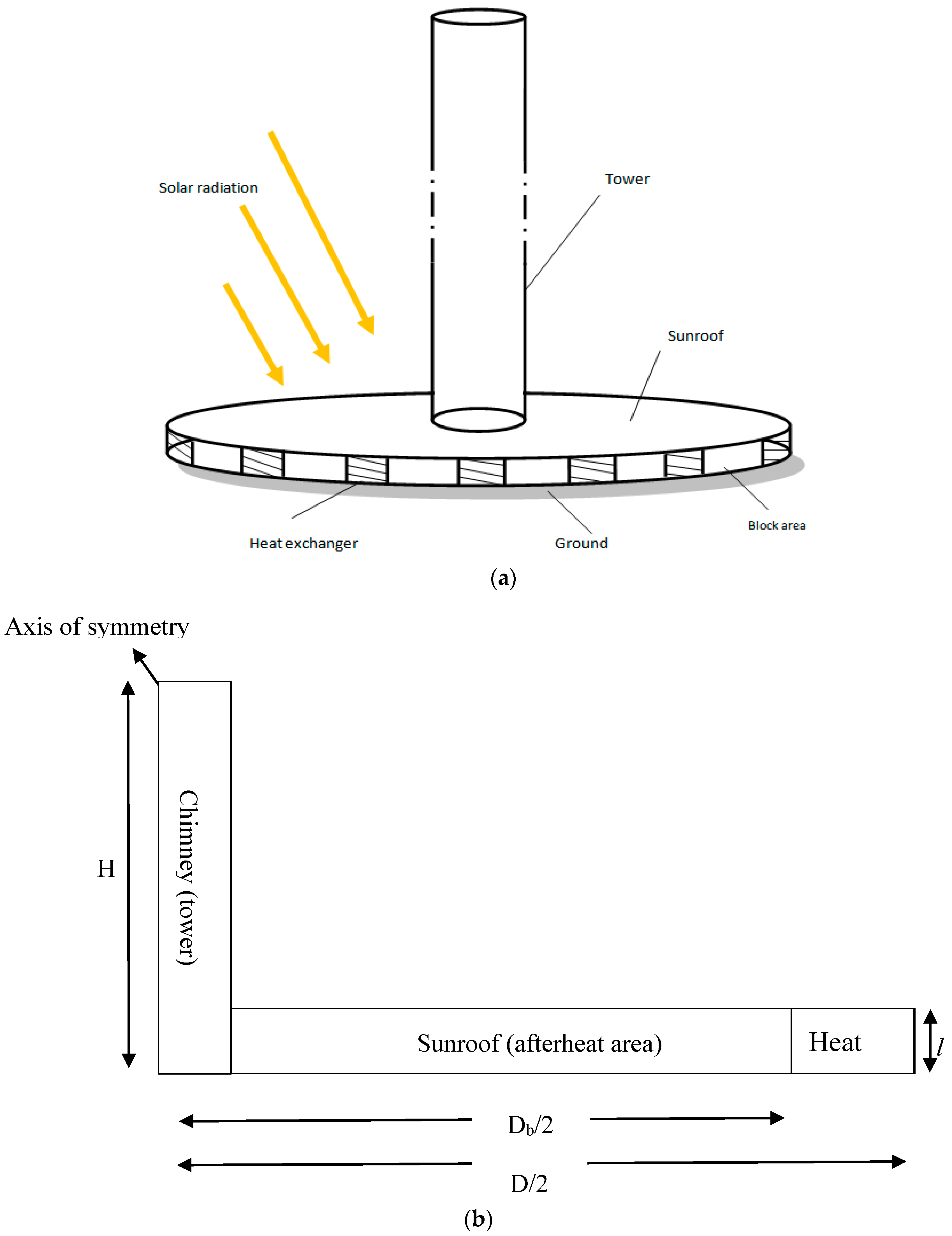
Figure 1. In his design, Zou (2014) blocked parts of the tower inlet to allow for compact multi-row heat exchangers in the remainder of the inlet area. As a result of buoyancy, the air is drawn to the tower through the heat exchangers and then, after removing the heat from the bundles, the air is further heated by the sun. This further accelerates the flow by reducing the air density, leading to higher air speed at the tower inlet, and thereby improving the heat transfer rate.
Concurrently, in order to improve the heat transfer rate from the condenser of a geothermal power plant, metal foam heat exchangers, as alternatives to finned tubes, have been investigated by Odabaee et al. [
9,
10,
11]. Such heat exchangers offer better flow mixing, and lead to heat transfer augmentation as a result of boundary layer interruptions at the pore level. They embrace small continuously-connected ligaments in an open-celled structure. These cells are usually polyhedrons of 12–14 faces, each of which has a pentagonal or hexagonal shape (by five or six filaments).
Figure 2 shows a sample of the aluminium foam wrapped around 3 cm diameter tubes that were used for the experiments. The experimental results of Chumpia and Hooman [
12] led to correlations for flow and thermal resistance of such foam-wrapped tubes in cross-flow, where hot water in the tube side is cooled by the air pushed across the tube in a horizontal wind tunnel.
In the forthcoming section, it will be shown that using the proper combination of single-row widely spaced tubes, rather than multi-row finned-tubes, in a SENDDCT leads to shorter towers being able to meet the required heat rejection rate for an air-cooled condenser. We used the experimental data from [
12] to address the thermo-hydraulics of the foamed tube bundles used as air-cooled condensers, and compared our predictions with the 3D numerical and 1D theoretical models of Zou [
5] as a case study.
2. Analysis
As explained, SENDDCT utilizes solar energy to heat the air as it leaves the heat exchangers with the goal of increasing the buoyancy forces, thereby leading to higher draft speed; hence, shorter towers can be realized. The heat transferred from the hot fluid in the heat exchanger,
Qa, increases the air enthalpy manifested in a temperature rise as
Going under the sunroof, the solar irradiation is absorbed by the air stream. This can be expressed as
where
As is the sunroof (panel) area, substituting for which leads to
Aiming at finding the temperature rise as a result of solar heating, one rearranges the above equation and substitutes for the air flow rate (using continuity equation) to get
The total temperature rise is then given by adding Equations (1)–(4), i.e.,
On the other hand, the required pressure difference, acting as the driving force, is given by
Or rearranged as
with the Gebhart number defined as
In the above equations, the air-specific heat at constant pressure is given by cp and the air flow rate is given by , with l being the tower inlet opening height, D the sunroof diameter, Db the tower base diameter, ρ the air density, β the thermal expansion coefficient, H is the tower height and g is the gravitational acceleration.
Now the temperature difference is higher than the case with no solar heating. As such, Equation (6) reads
Rearranging the above, in terms of a goal function, the following equation is obtained
The left side of the above equation,
F, indicates the pumping power divided by the heat transferred from the bundle. Thereby, one can try to minimize this function, which, in turn, means the right-hand side has to be minimized by finding a proper combination of the parameters in the right side. For a tower with a set heat-transfer duty, height and base diameter, one can change the sunroof diameter to optimize the system. As such, one can differentiate the above equation with respect to
D and set it to zero
to find the optimal
D value for which the excess pressure drop is minimized. This will lead to
One verifies the second derivative condition check
that is, the value found for
D in Equation (12) leads to a minimum for
F.
One uses the above optimal sunroof diameter, given in Equation (12), to find the optimal
F value, as
One can now rearrange the above equation corresponding to the following maximum heat transfer rate, with minimal pressure drop combination, as
The above formula optimizes an already designed tower for the addition of sunroof area. However, it does not tell us how a tower should be optimized with built-in solar heating. One answer to this question will be through minimizing tower losses; above all, the loss posed by the heat exchangers. Heat exchangers are usually designed in the form of multi-row bundles simply because area is limited. Moreover, the tubes in the first rows of a multi-row finned-tube bundle act as turbulence generators for subsequent rows, resulting in higher heat transfer rates for subsequent tubes. Furthermore, spacing the tubes densely leads to high-speed local jets for the deeper rows, which, in turn, will augment the heat transfer compared to sparsely-bundled finned-tubes. It is well documented in the literature that denser tube bundles lead to higher pressure drops, which have to be compensated for through the use of taller towers, which translates into extra cost. Besides, the tubes cannot be too densely set, as there must be space for cleaning of the heat exchangers and regular maintenance procedures.
With a SENDDCT, compared to a NDDCT, there is more area available at the skirt of the tower, where cold air is sucked into the tower through the heat exchangers, mainly as a result of the inclusion of the collector plates (sunroof). Hence, one can use single-row heat exchangers leading to much lower pressure drops compared to current technology being compact multi-row heat exchangers. For a vertical arrangement of the heat exchangers, this total heat is transferred by a number of tubes of external (fin or foam) diameter
d, spaced
sd apart,
N, which is given by
With an average heat transfer per tube given by
q, one gets
Qa = Nq. If the tubes are widely spaced, then
q is the same as that given by a single tube in cross flow not disturbed by adjacent objects. With denser tube bundles, however, this is not the case. One can still define a per-tube heat transfer rate, but that will not be the same as the heat transfer from a single tube in cross flow. Combining the above equation with Equation (1), and substituting for the air-mass flow rate given by the continuity equation, one gets
One notes that this increase in temperature is not the same as that of an identical tower with no solar heating. This is to be expected as the fluid velocity, generated by the upward draft, is dissimilar in the two settings (a SENDDCT and a NDDCT of the same height with the same heat exchangers applied in both designs) due to solar after-heating.
Here, the heat transfer per tube can be furnished through the use of the available experimental data and correlation in [
12], i.e.,
where
R is the overall thermal resistance given as a function of approach velocity
U by
with
Dr being the tube’s outer (foam or fin) diameter divided by that of the bare tube. For a bare tube bundle,
Dr = 1. Moreover, the temperature difference
is the difference between the ambient air and average tube surface; the latter is very close to the average cycle fluid temperature or the condensation temperature. As such, this
can be thought of as
approach.
Furthermore, combining Equations (4), (18) and (19), the total increase in the air temperature, on top of the ambient temperature, is given by
This leads to the total suction (buoyancy-induced) pressure difference, here the driving force, of
Furthermore, the bundle pressure drop, which is the dominant resistance to air flow in the tower, is given by
Through the use of complex 3D CFD simulations, Zou [
5] showed that the heat exchanger losses account for about 90% of the total losses. This is in line with the scale analysis and numerical results reported in [
13,
14,
15] for a NDDCT with no solar enhancement. Going with a more conservative assumption of 20% non-heat exchanger losses, one can balance the projected total loss with the driving force, leading to the SENDDCT height given by
Note that, depending on U, one can get different tower heights from the above (draft-like) equation. These H values satisfy the draft equation for a certain velocity, approach and geometrical values. Furthermore, the total heat dump associated with each U and H combination is fixed, and is given by Equation (1).
3. Results
In order to compare the single-row design suggested here with the multi-row data pertinent to SNDDCTs, the assumptions made in Zou et al. [
6] are recovered. There it was shown that, with a tower height of 140 m, about 135 MW of heat can be dumped. The tower base diameter was 100 m, with the bundle height being equal to 15 m. A total of 243 vertical 3-row bundles with 36 tubes per row were used. This translates into 26,244 tubes with an inner diameter of just under 4 cm with a
Dr value of 1.75. Different sunroof diameters, ranging from
D = 195 m to
D = 475 m were examined. The whole 3D system was simulated using ANSYS and the numerical results and 1D theoretical prediction were cross-validated.
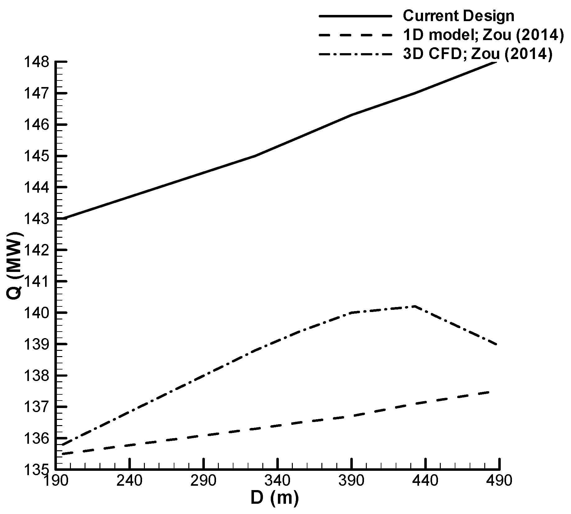
Figure 3 shows a comparison between the new design offered here and that of Zou et al. [
6,
7,
8], as summarized in [
5].
Note that about a 7% increase in net heat dump can be expected based on the design offered here. It is a significant improvement in the tower performance, i.e., instead of rejecting 136 MW, the same tower can remove 143 MW. For a plant that generates power at about 40% efficiency, this 7 MW higher heat duty translates into about 3 MW more generation, or about 3% higher net efficiency. With increasing costs and demand for electricity, the economical saving associated with this will be even more valuable in the long run. Another interesting observation can be made when one compares the number of tubes used in Zou et al. [
6], which was 26,244 tubes—with that of the proposed design, which only uses about 7000 tubes; just above a quarter of the total tubes. This represents a significant saving in materials and also, in the long run, maintenance costs. For a more comprehensive understanding of the problem,
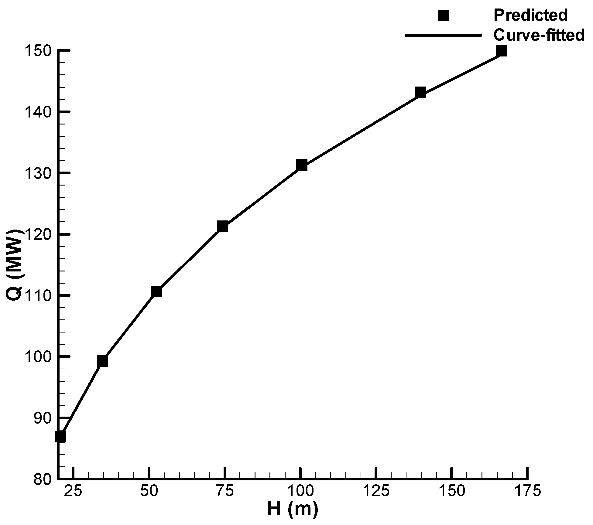
Figure 4 is presented to show the total heat transfer versus the tower height. Equation (23) is used to plot the required height for a tower to dump 135 MW of heat with and without solar enhancement for a single row metal foam heat exchanger. The predicted data is also curve-fitted for easier use and future application, as the total heat transfer is implicit in Equation (23). The curve fit is simple, implies a
H~U2 law, and reads
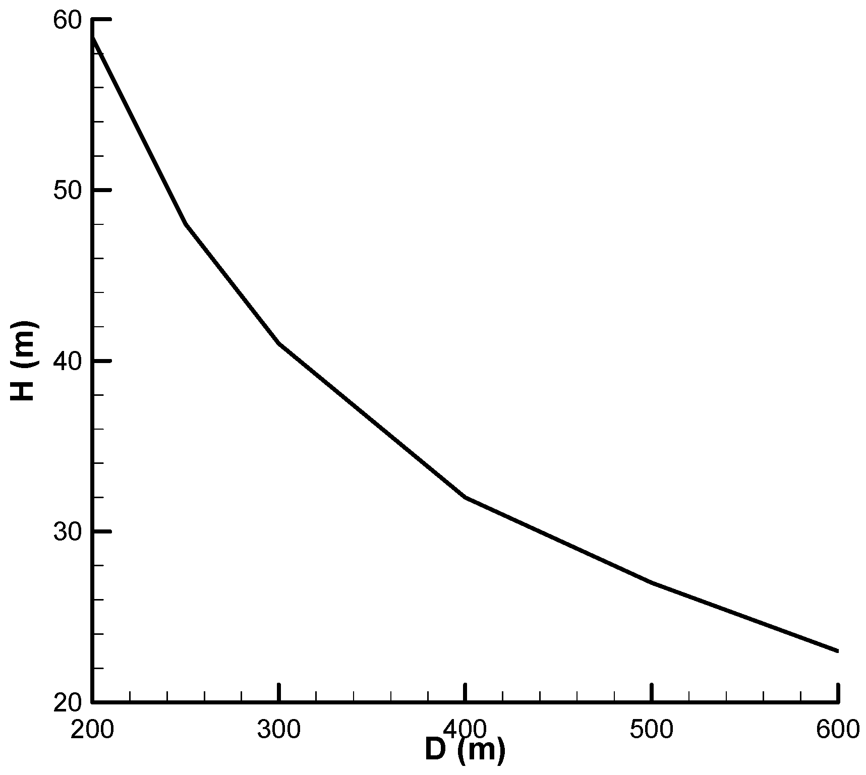
The height is shown versus the sunroof diameter in
Figure 5. As can be seen, increasing the sunroof diameter leads to lower tower height. In the limit, when
D → ∞, one expects
H → 0, as Equation (23) indicates. Interestingly, when the sunroof diameter is tripled, the tower height is reduced by an order of magnitude. This is a significant tower cost reduction, which will be balanced with the extra sunroof cost. Obviously, factors like easy installation at a lower height and the possibility of selecting a less expensive sunroof material as opposed to concrete tower structure need to be taken into account. A cost optimization is not, however, within the scope of this study, and can be postponed to a future study.
Figure 6 uses the same design parameters as those of Zou et al. [
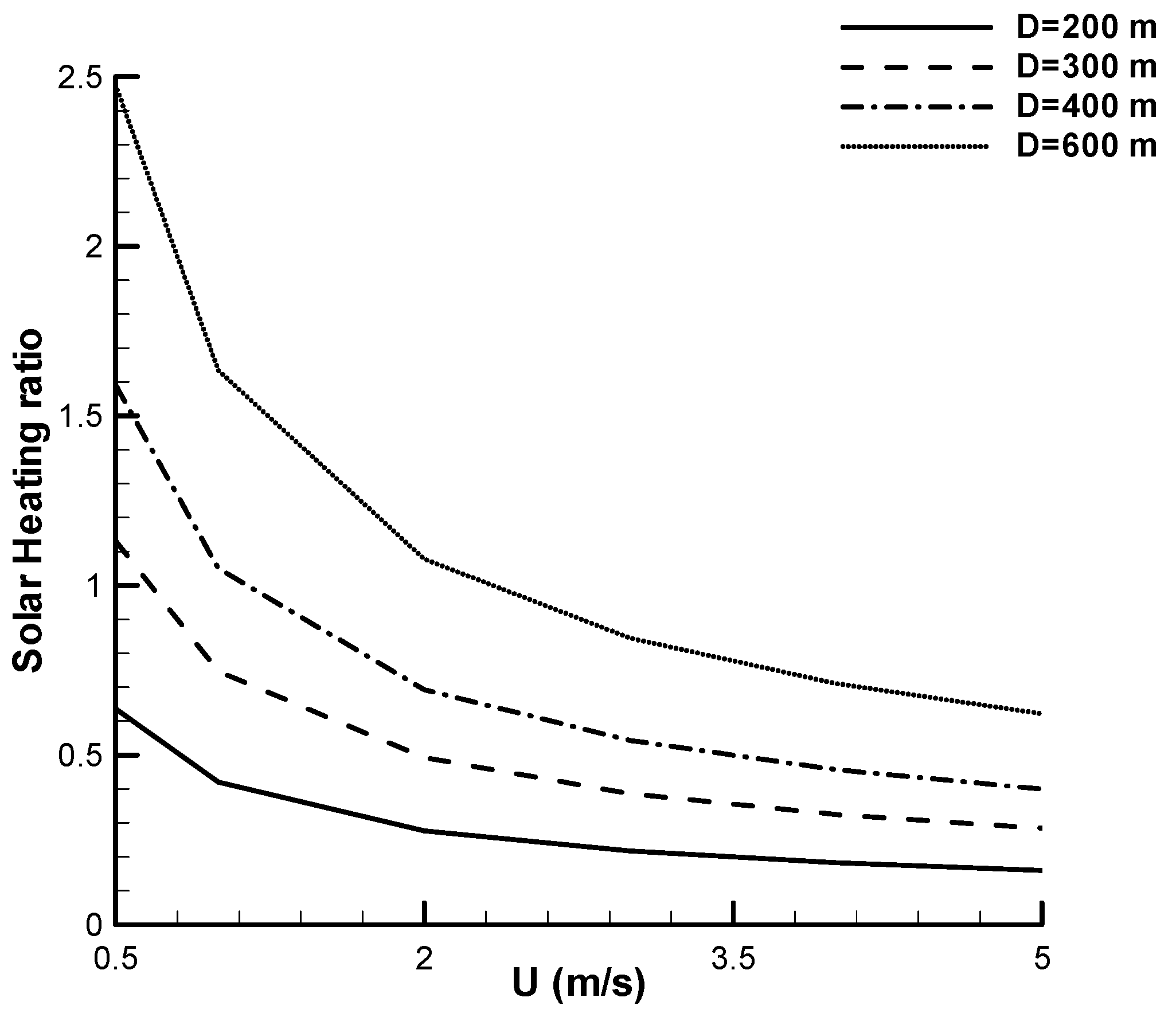
6] for the tower size to indicate the effectiveness of solar after-heating. Note that the driving force is proportional to the air-temperature rise. The air temperature increases as a result of heat transfer from the cycle fluid to the air, and then the heat gain from the sunroof. While the former has to be augmented to meet the heat rejection need, any increase in the latter can compensate for the tower height. As such, the designer needs to keep a close eye on the comparison between the two heating scenarios to come up with an optimal design. In generating
Figure 6, different velocity values are assumed, regardless of tower height, to give an idea of the effectiveness of solar after-heating. As expected, solar enhancement is more pronounced at lower air flow rates as a result of less efficient heat removal from the heat exchangers as opposed to less flow rate-dependent heat gain of the air stream under the sunroof. For instance, at low air flow rates, with a short sunroof diameter of about 200 m (where the base tower diameter is 100 m), the air temperature rise due to solar heating is about half of that caused by the heat exchangers. Even with that, one expects a total air temperature difference of about 1.5 times that of heat exchangers only. With everything else unaltered, which does not necessarily have to be the case, the corresponding tower height can now be reduced by about 30%. Nonetheless, at higher flow rates—say, when the air speed is about 3 m/s, as in the case studied in [
6]—the enthalpy rise as a result of solar heating is only about 20% that caused by the heat exchangers. One notes that the above numbers given as “reduction in height” are only accurate if the NDDCT uses the same heat exchangers as SENDDCT, in this case, single-row bundles, which do not increase the air temperature by as much as multi-row heat exchangers do.
Interestingly, these are results for a single-row foamed design. As the foams do not have to be bundled densely to lead to a high heat-transfer rate, see [
16] Hooman (2014), the second row can be spaced so widely that the pressure drop is only double that of a single tube, which is still lower than the pressure drop of a two-row dense bundle due to local blockage in the heat exchanger.


