An Improved Control and Energy Management Strategy of Three-Level NPC Converter Based DC Distribution Network


Abstract
:1. Introduction
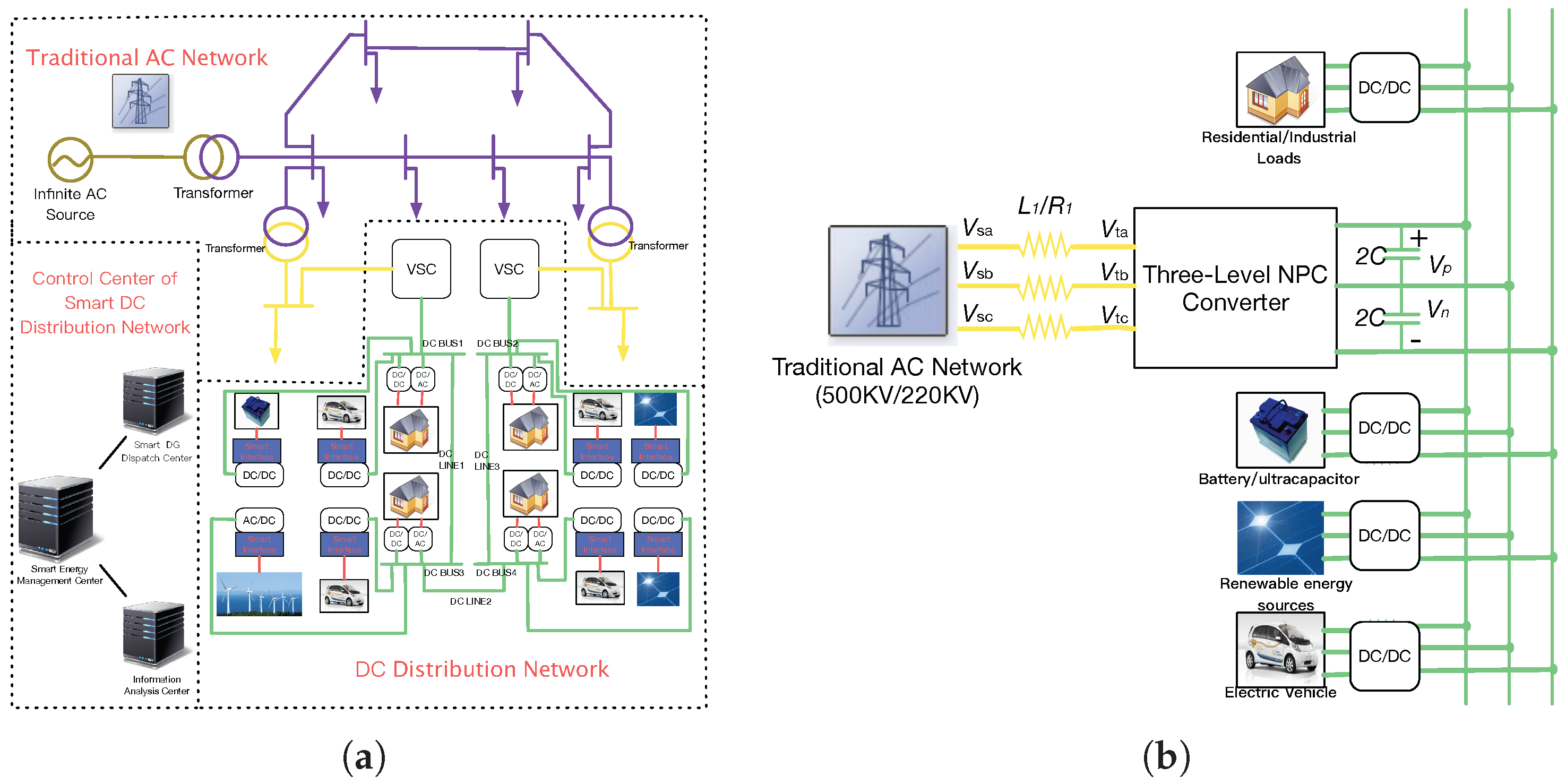
2. DC Distribution Network
2.1. Proposed DC Distribution Network
2.2. The Simplified DC Distribution Network
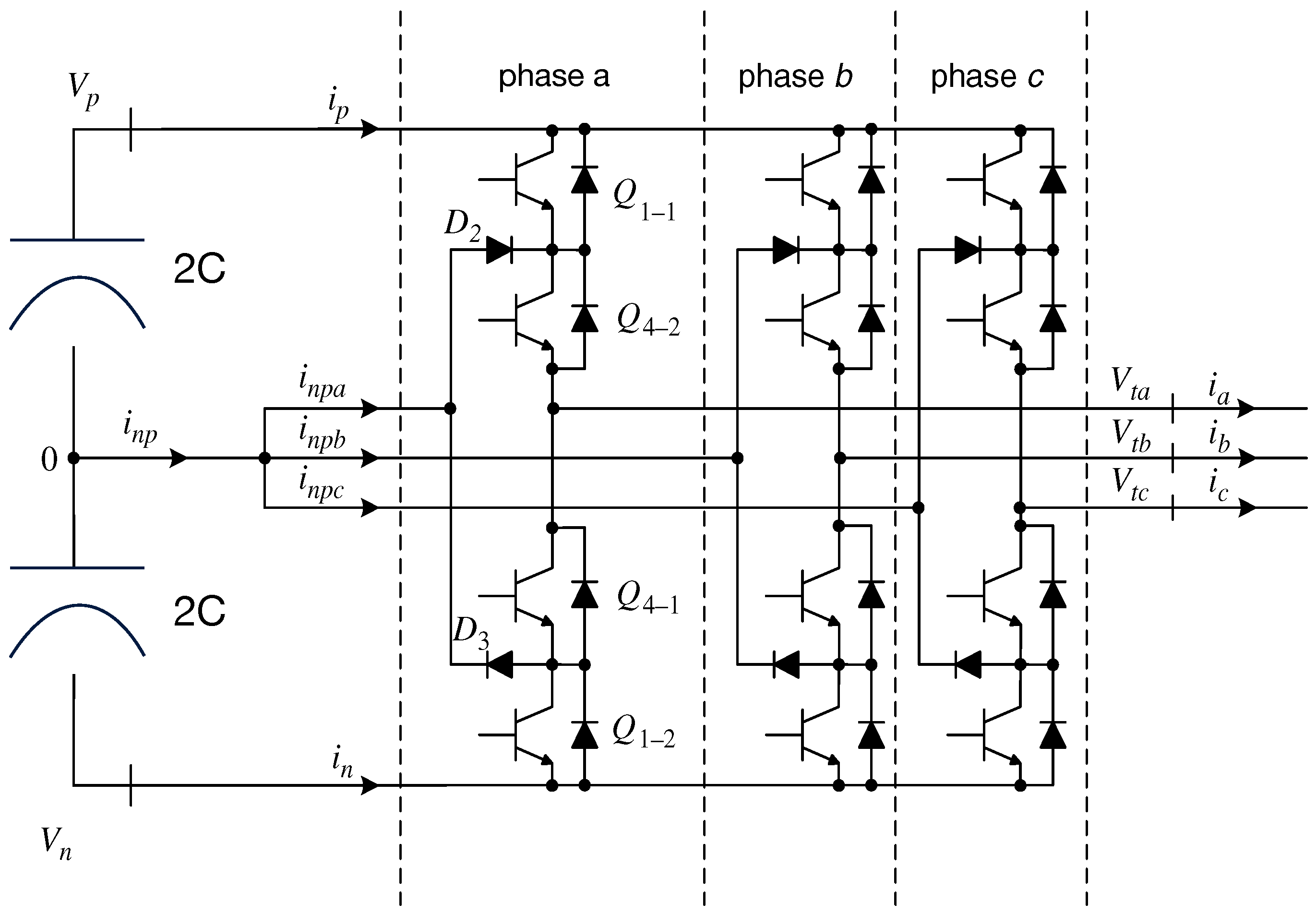
3. Model of Three-Level NPC Converter
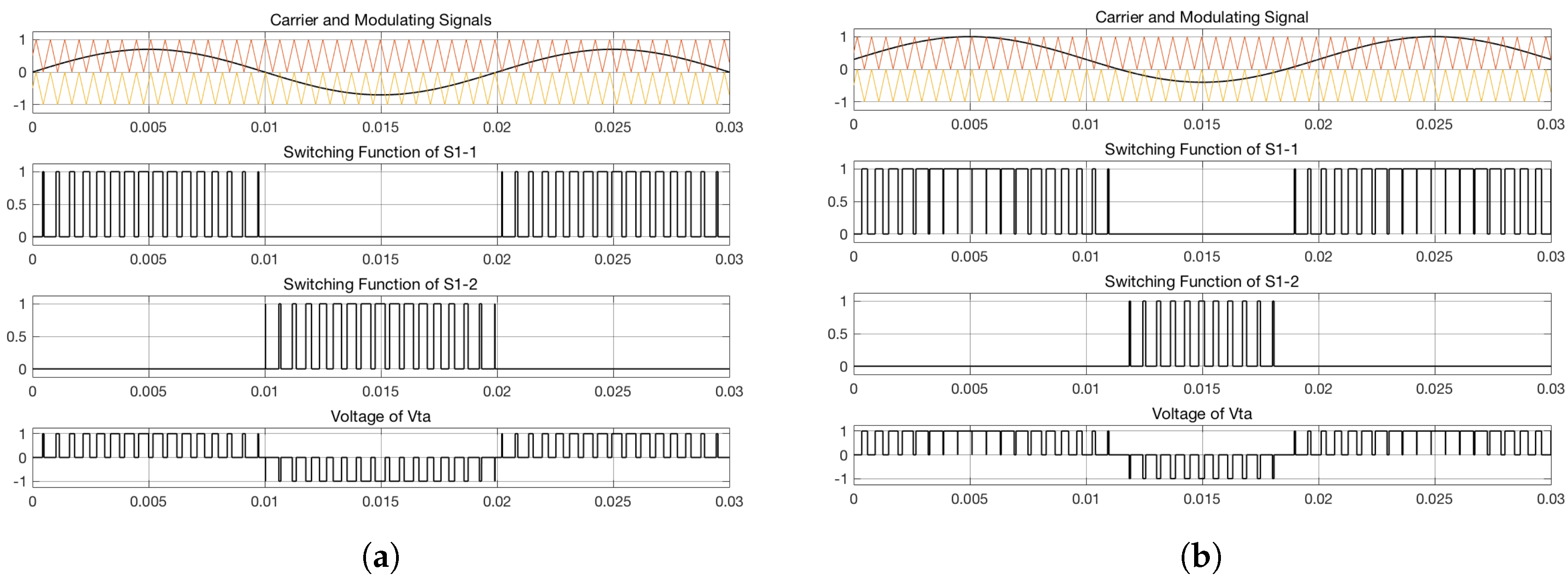
3.1. Voltage of AC Side
3.2. Voltage of DC Side
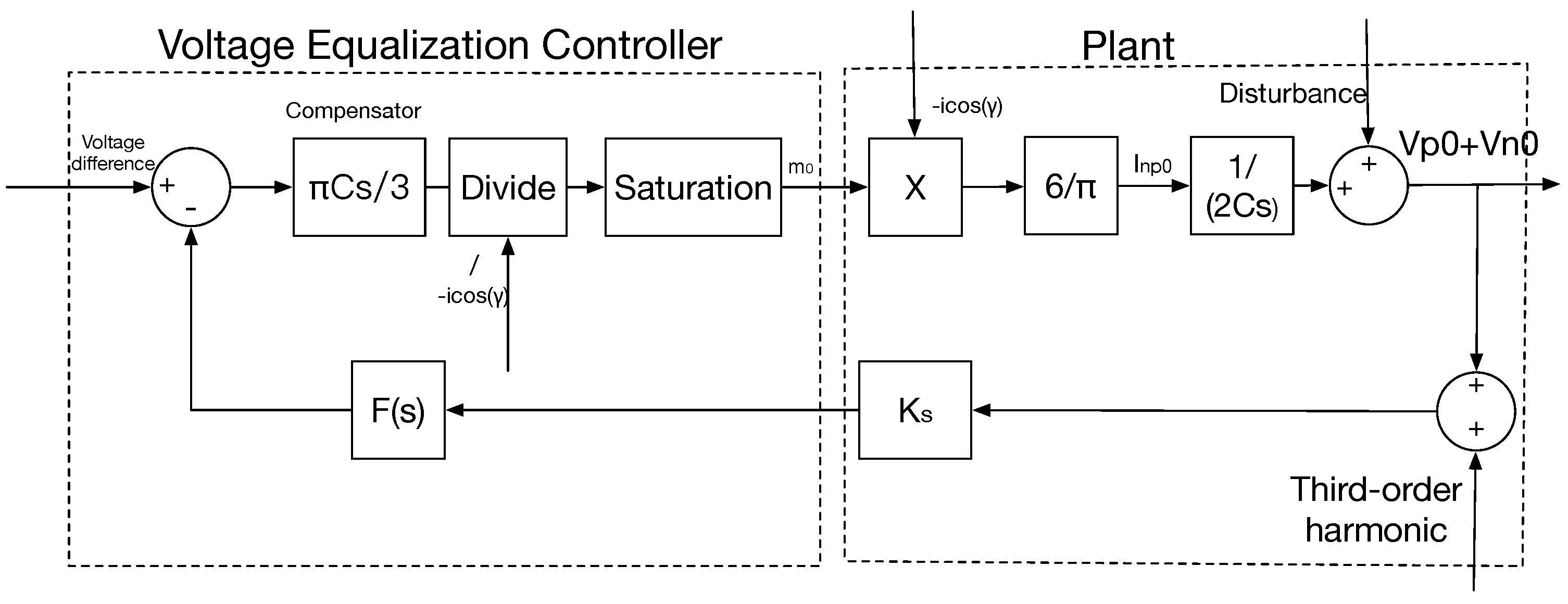
3.3. Voltage Equalization Problem of the DC Side
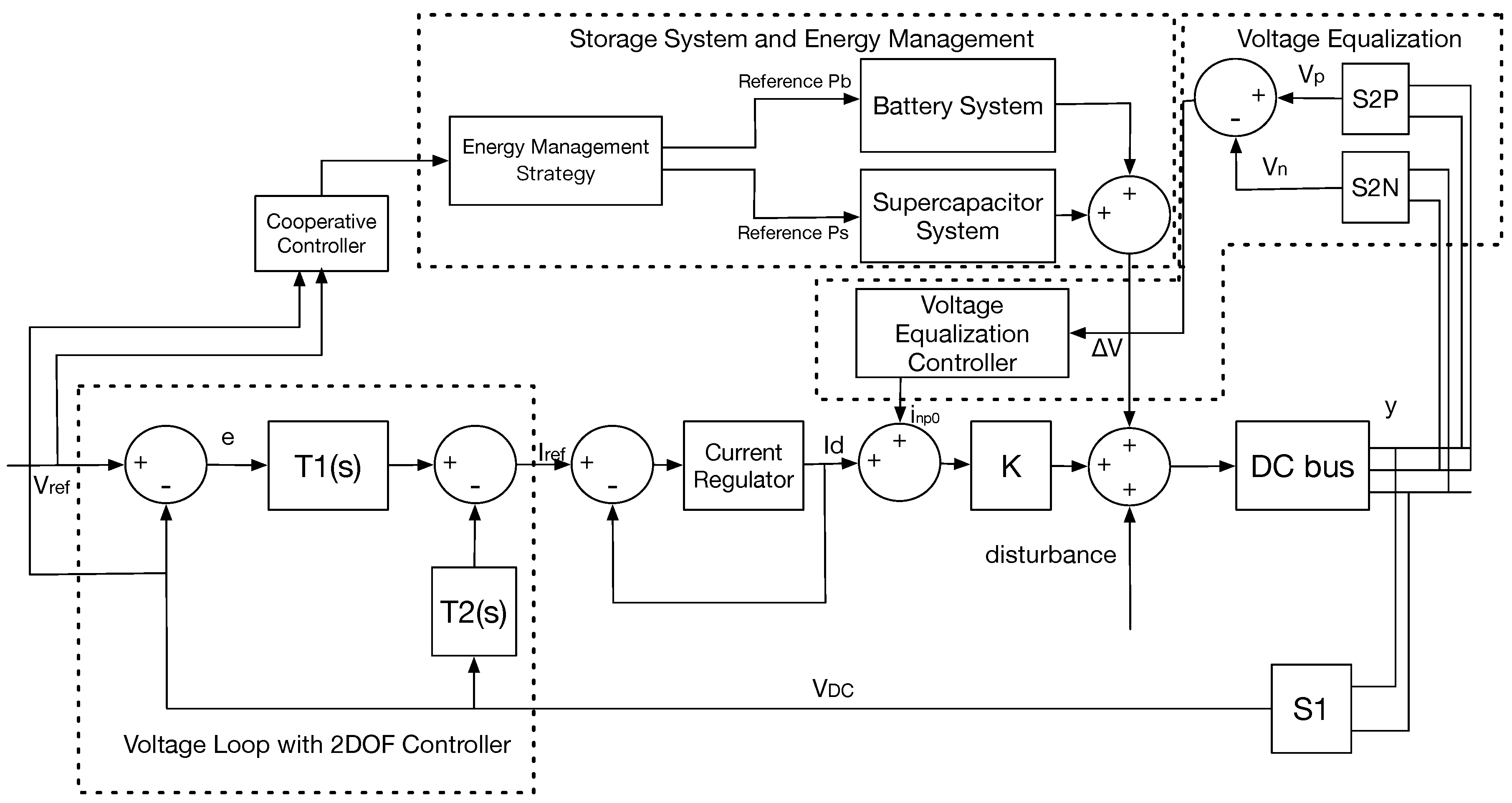
3.4. Structure of Control System
4. Improved Strategy
4.1. Voltage Equalization Control
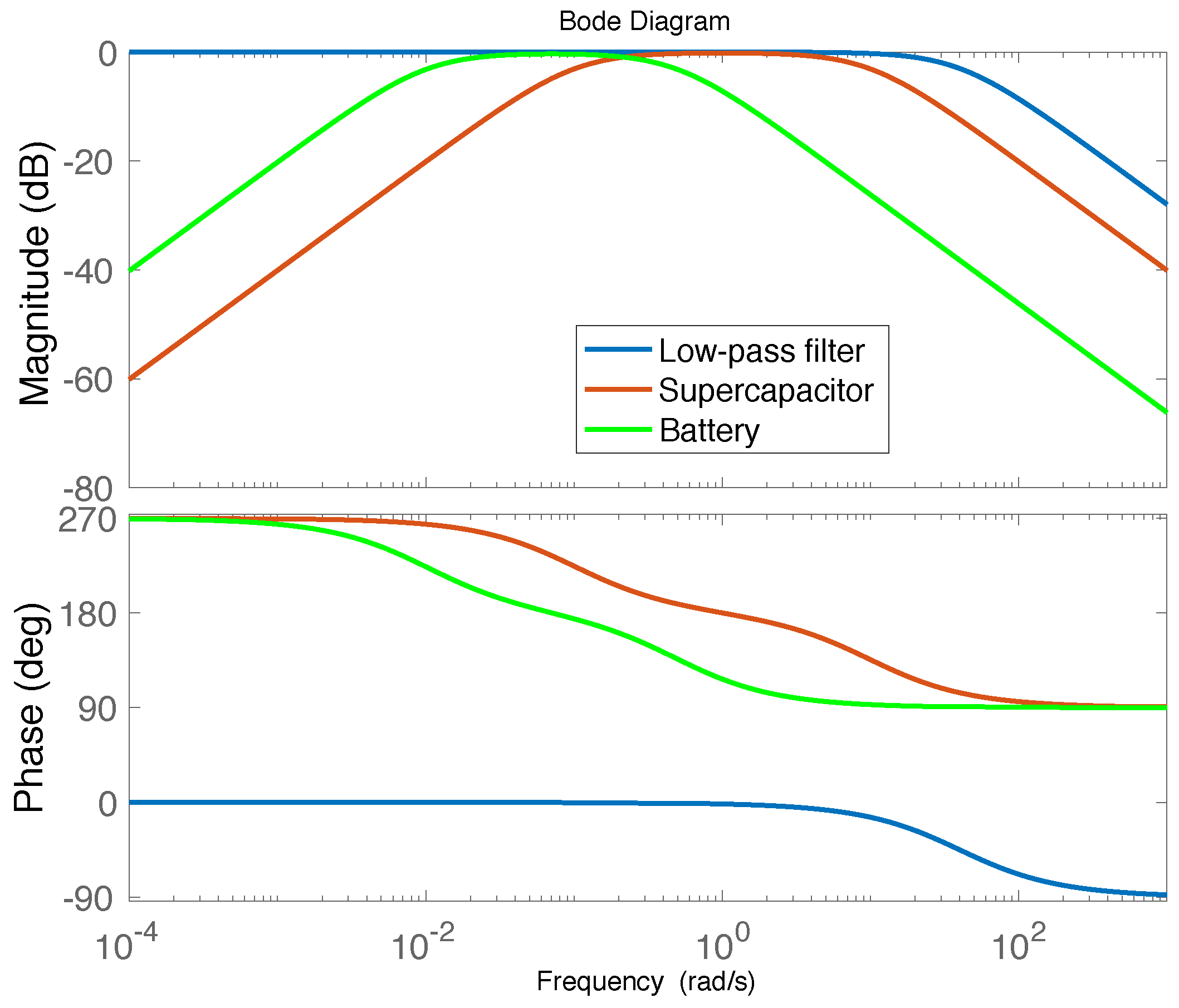
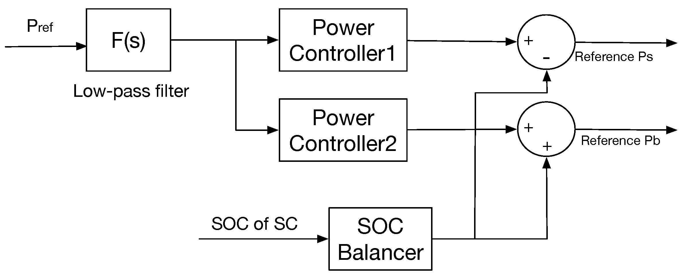
4.2. Cooperative Control with Storage System
4.3. Energy Management Strategy of the Storage System
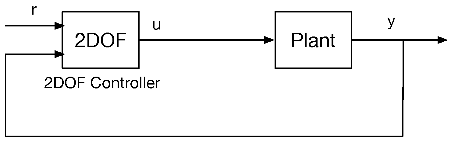
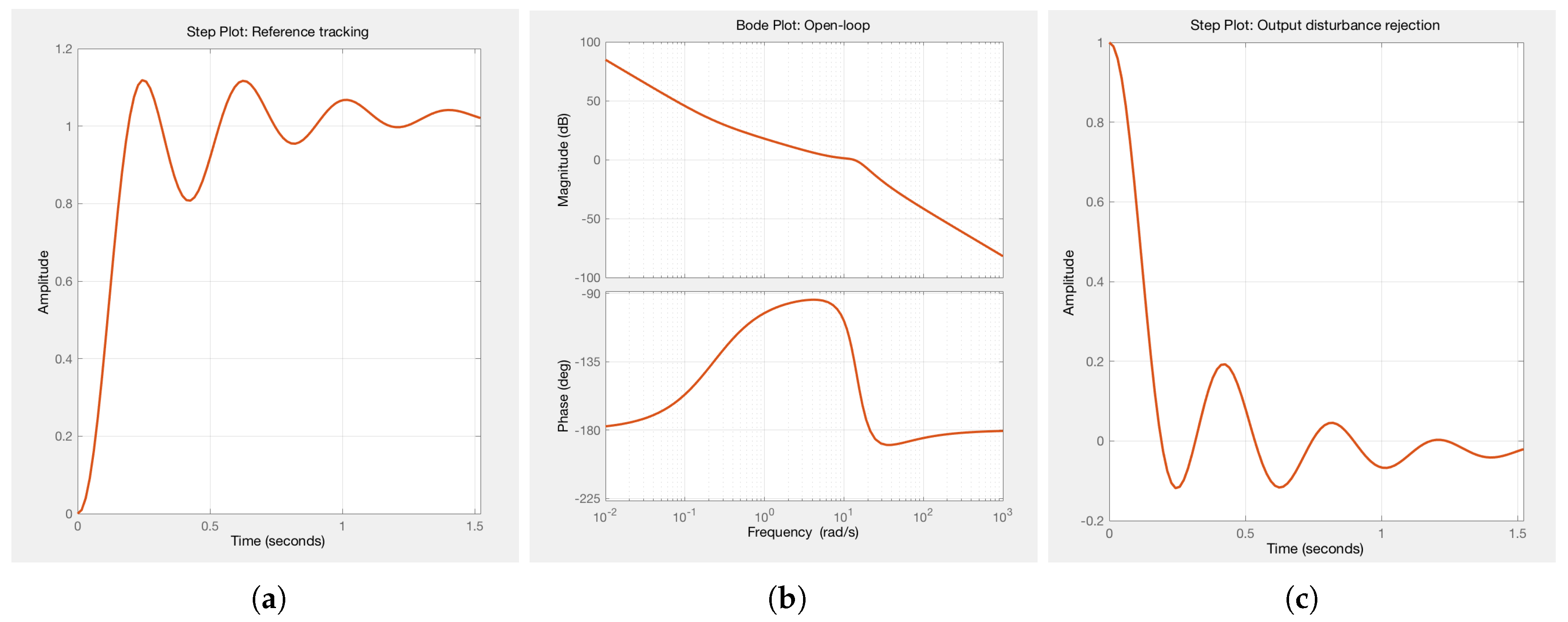
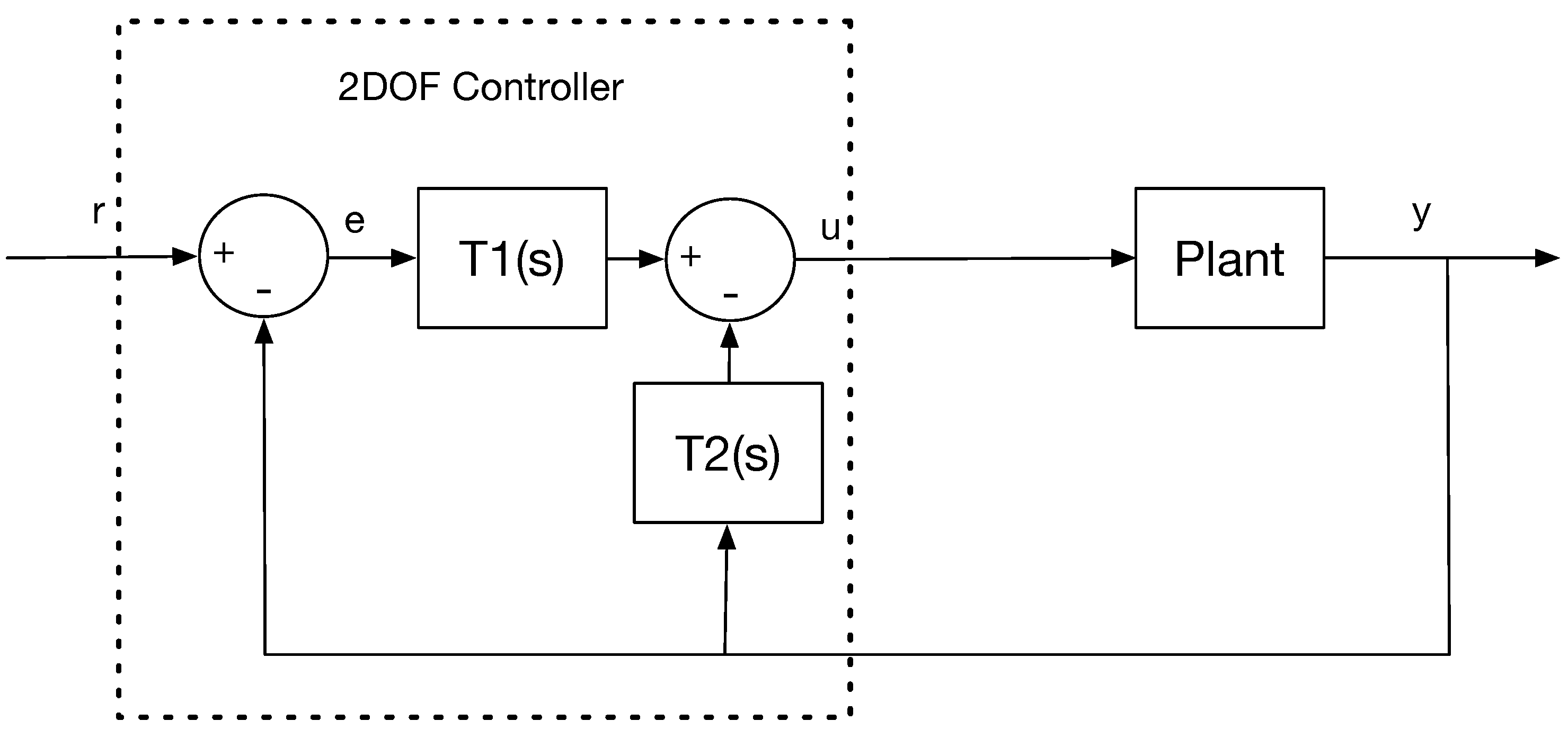
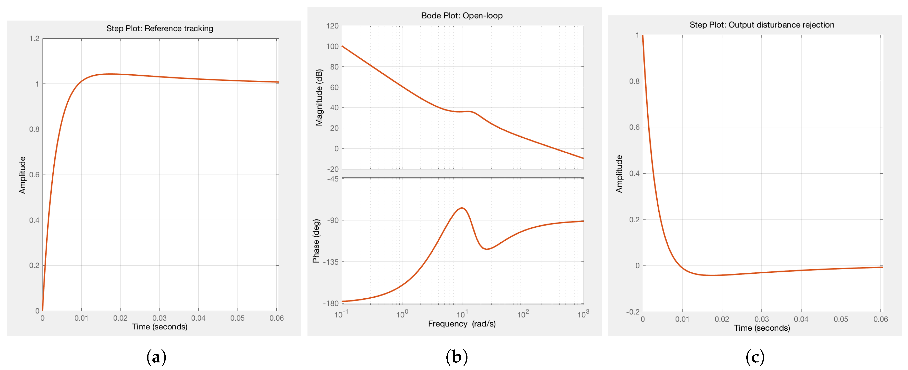
4.4. Two-Degree-of-Freedom Controllers
5. Verification
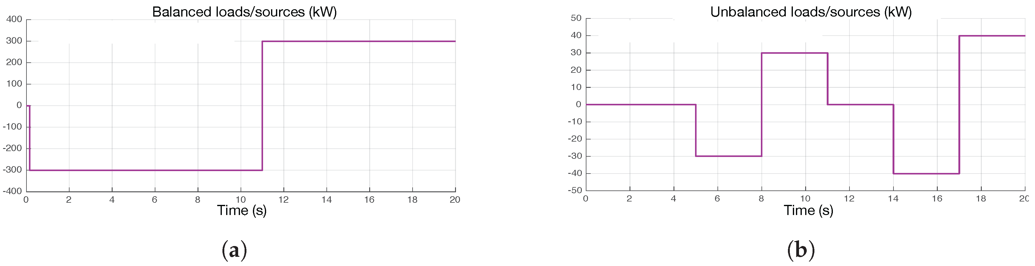
5.1. Test Scenario
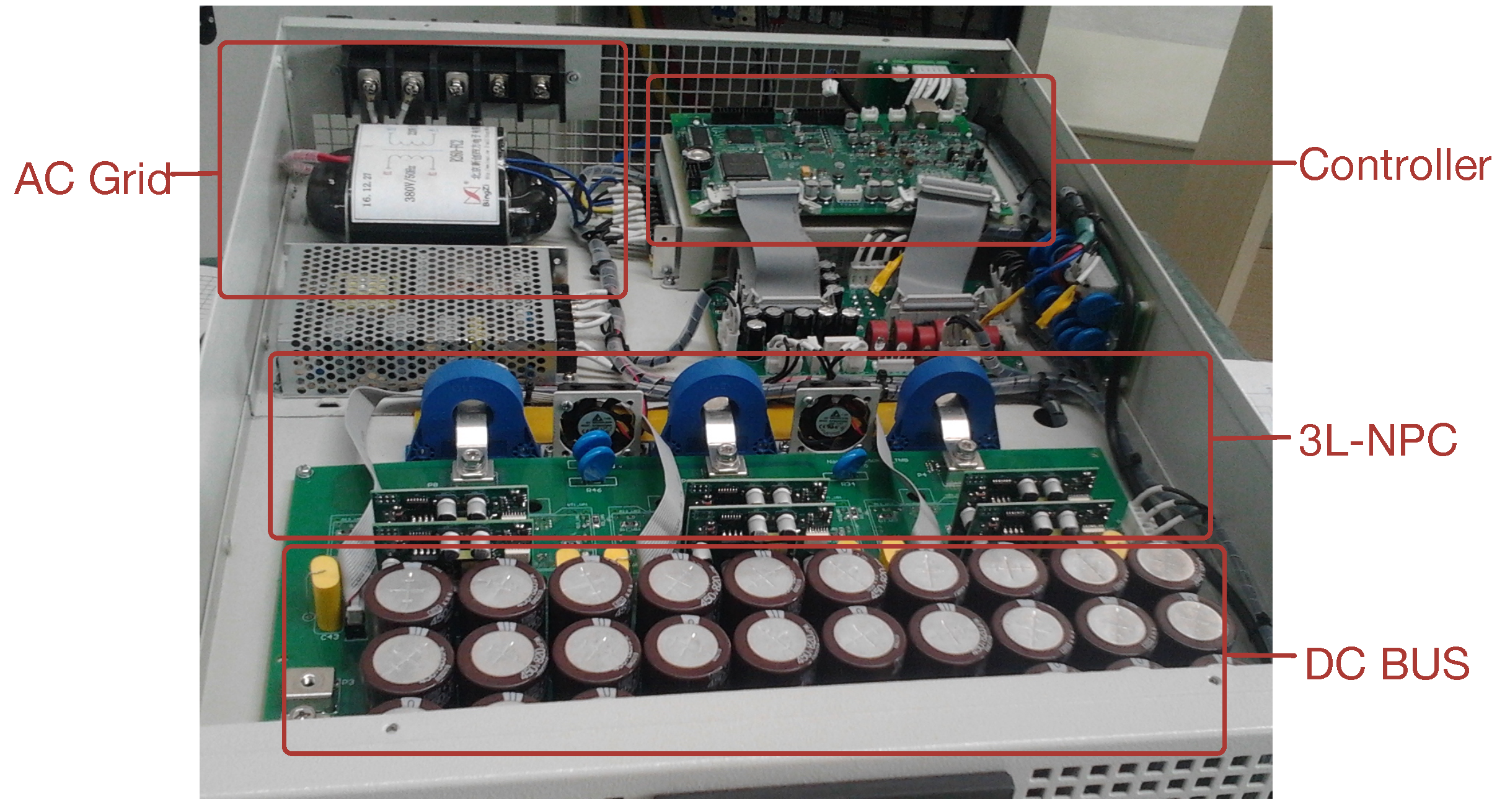
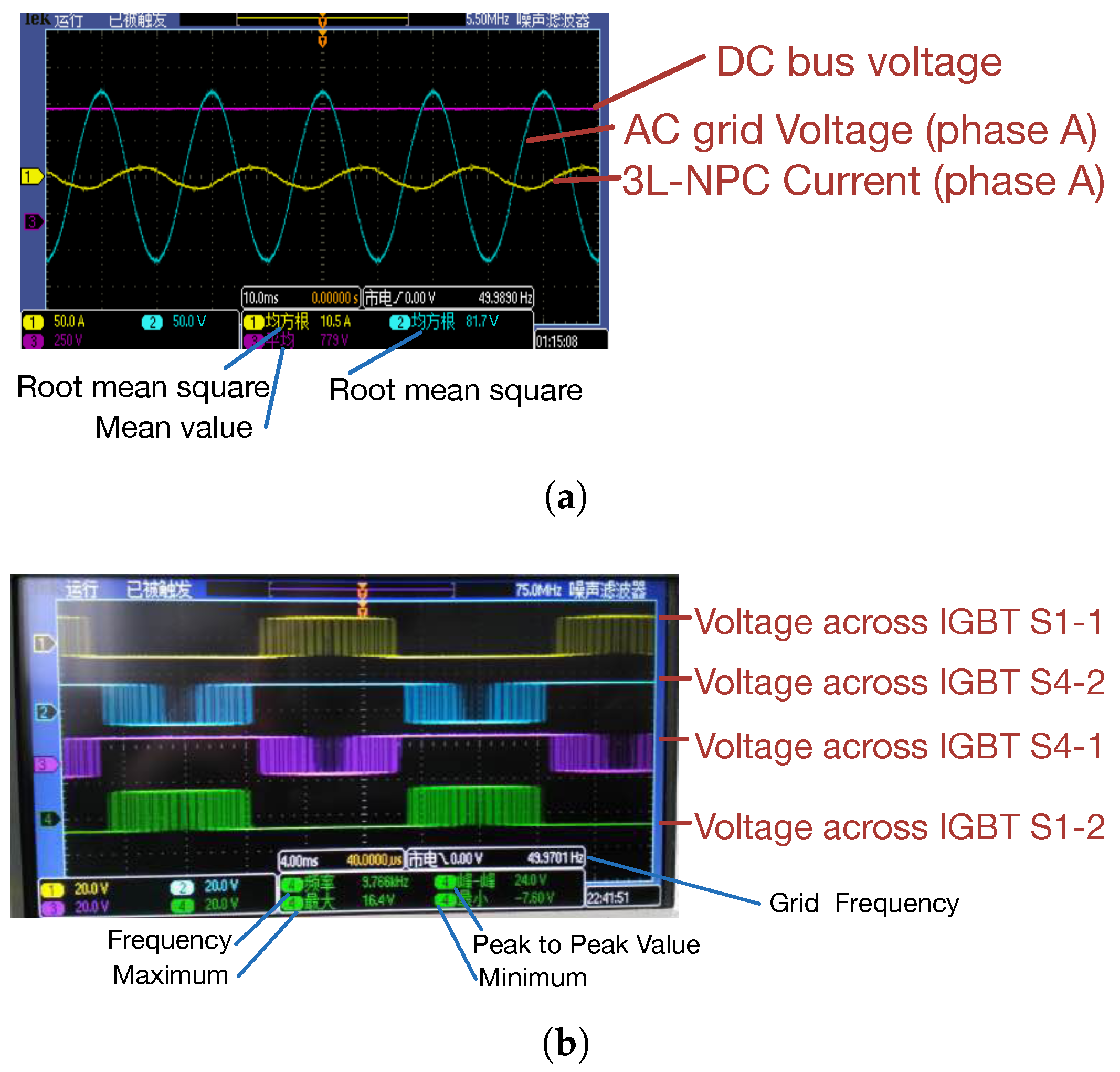
5.2. Three-Level NPC
5.3. Traditional Control
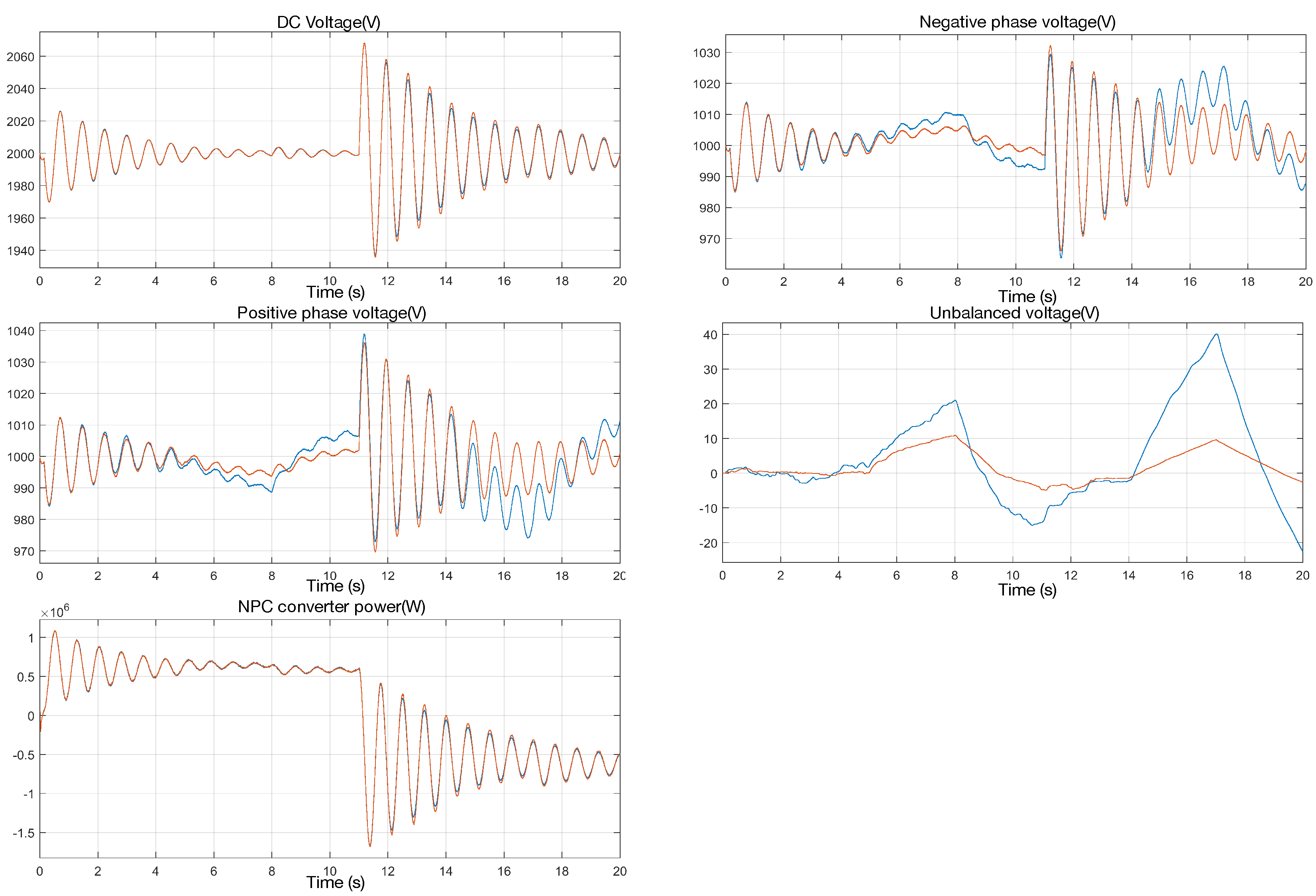
5.4. Voltage Equalization Controller
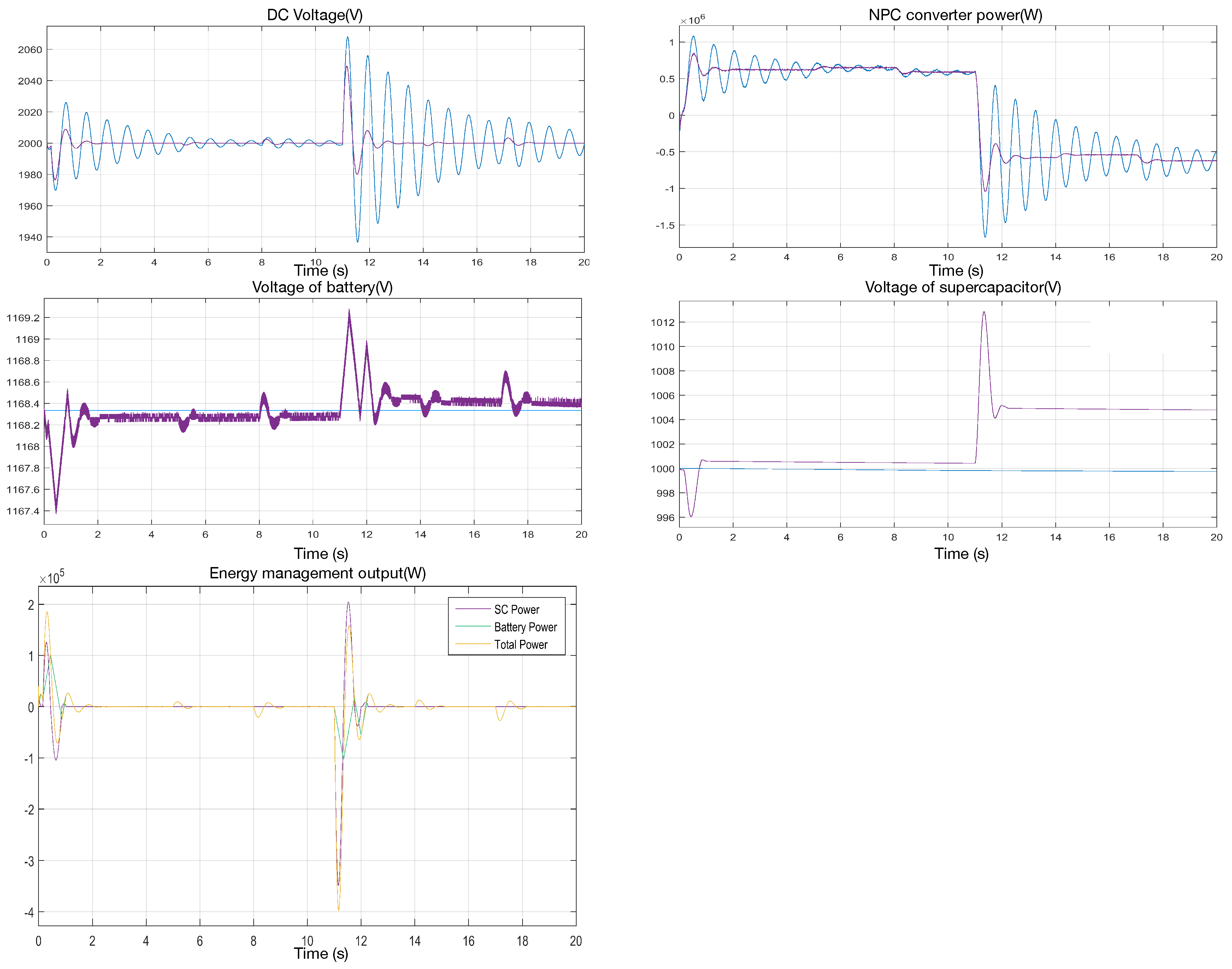
5.5. Cooperative Control and Energy Management Strategy
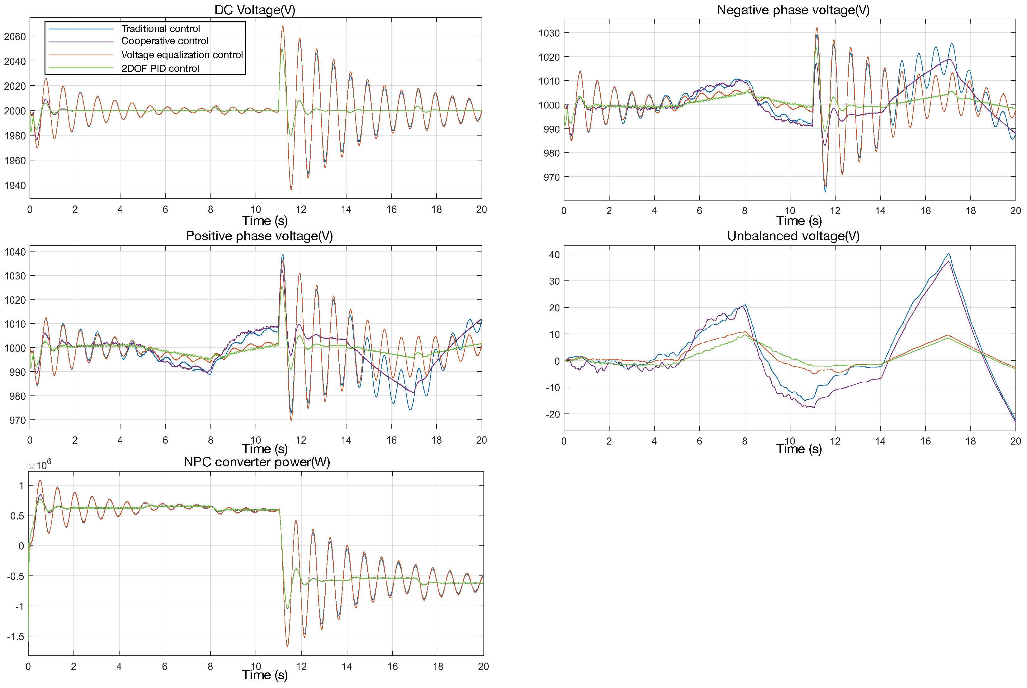
5.6. Synthetic Control Results
6. Conclusions
Acknowledgments
Author Contributions
Conflicts of Interest
Abbreviations
| DER | Distributed Energy Resource |
| NPC | Neural Point Clamped |
| 2DOF | 2-Degrees of Freedom |
| MCU | Micro Controller Unit |
| VSC | Voltage Source Converter |
| RES | Renewable Energy Source |
| ESS | Energy Storage System |
| PWM | Pulse Width Modulation |
| DSP | Digital Signal Processing |
| AC | Alternating Current |
| DC | Direct Current |
| IGBT | Insulated Gate Bipolar Transistor |
| PI | Proportional-Integral |
| PID | Proportional-Integral-Derivative |
References
- Katiraei, F.; Iravani, R.; Hatziargyriou, N.; Dimeas, A. Microgrids management. IEEE Power Energy Mag. 2008, 6, 54–65. [Google Scholar] [CrossRef]
- Saeedifard, M.; Graovac, M.; Dias, R.F.; Iravani, R. DC power systems: Challenges and opportunities. In Proceedings of the Power and Energy Society General Meeting, Minneapolis, MN, USA, 25–29 July 2010; pp. 1–7. [Google Scholar]
- Kakigano, H.; Miura, Y.; Ise, T.; Uchida, R. DC voltage control of the DC micro-grid for super high quality electric power distribution. IEEJ Trans. Ind. Appl. 2007, 127, 890–897. [Google Scholar] [CrossRef]
- She, X.; Lukic, S.; Huang, A.Q. DC zonal micro-grid architecture and control. In Proceedings of the IECON 2010-36th Annual Conference on IEEE Industrial Electronics Society, Glendale, AZ, USA, 7–10 November 2010; pp. 2988–2993. [Google Scholar]
- Liu, B.; Zhuo, F.; Zhu, Y.; Yi, H. System operation and energy management of a renewable energy-based DC micro-grid for high penetration depth application. IEEE Trans. Smart Grid 2015, 6, 1147–1155. [Google Scholar] [CrossRef]
- Hosseinzadeh, M.; Salmasi, F.R. Power management of an isolated hybrid AC/DC micro-grid with fuzzy control of battery banks. IET Renew. Power Gener. 2015, 9, 484–493. [Google Scholar] [CrossRef]
- Liu, X.; Wang, P.; Loh, P.C. A hybrid AC/DC microgrid and its coordination control. IEEE Trans. Smart Grid 2011, 2, 278–286. [Google Scholar]
- Radwan, A.A.A.; Mohamed, Y.A.R.I. Assessment and mitigation of interaction dynamics in hybrid ac/DC distribution generation systems. IEEE Trans. Smart Grid 2012, 3, 1382–1393. [Google Scholar] [CrossRef]
- Chen, D.; Xu, L. Autonomous DC voltage control of a DC microgrid with multiple slack terminals. IEEE Trans. Power Syst. 2012, 27, 1897–1905. [Google Scholar] [CrossRef]
- Radwan, A.A.A.; Mohamed, Y.A.R.I. Linear active stabilization of converter-dominated DC microgrids. IEEE Trans. Smart Grid 2012, 3, 203–216. [Google Scholar] [CrossRef]
- Balog, R.S.; Weaver, W.W.; Krein, P.T. The load as an energy asset in a distributed DC smartgrid architecture. IEEE Trans. Smart Grid 2012, 3, 253–260. [Google Scholar] [CrossRef]
- Hossain, M.R.; Ginn, H.L. Real-Time Distributed Coordination of Power Electronic Converters in a DC Shipboard Distribution System. IEEE Trans. Energy Convers. 2017, 32, 770–778. [Google Scholar] [CrossRef]
- Gwon, G.H.; Kim, C.H.; Oh, Y.S.; Noh, C.H.; Jung, T.H.; Han, J. Mitigation of voltage unbalance by using static load transfer switch in bipolar low voltage DC distribution system. Int. J. Electr. Power Energy Syst. 2017, 90, 158–167. [Google Scholar] [CrossRef]
- Baek, J.; Choi, W.; Chae, S. Distributed Control Strategy for Autonomous Operation of Hybrid AC/DC Microgrid. Energies 2017, 10, 373. [Google Scholar] [CrossRef]
- Suryanarayana, H.; Sudhoff, S.D. Design Paradigm for Power Electronics-Based DC Distribution Systems. IEEE J. Emerg. Sel. Top. Power Electron. 2017, 5, 51–63. [Google Scholar] [CrossRef]
- Makrygiorgou, D.I.; Alexandridis, A.T. Stability Analysis of DC Distribution Systems with Droop-Based Charge Sharing on Energy Storage Devices. Energies 2017, 10, 433. [Google Scholar] [CrossRef]
- Li, H.; Liu, C.; Li, G.; Iravani, R. An Enhanced DC Voltage Droop-Control for the VSC-HVDC Grid. IEEE Trans. Power Syst. 2017, 32, 1520–1527. [Google Scholar] [CrossRef]
- Chen, D.; Xu, L.; Yu, J. Adaptive DC Stabilizer With Reduced DC Fault Current for Active Distribution Power System Application. IEEE Trans. Power Syst. 2017, 32, 1430–1439. [Google Scholar] [CrossRef]
- Yao, J.; Li, H.; Liao, Y.; Chen, Z. An improved control strategy of limiting the DC-link voltage fluctuation for a doubly fed induction wind generator. IEEE Trans. Power Electron. 2008, 23, 1205–1213. [Google Scholar]
- Dong, D.; Cvetkovic, I.; Boroyevich, D.; Zhang, W.; Wang, R.; Mattavelli, P. Grid-interface bidirectional converter for residential DC distribution systems—Part one: High-density two-stage topology. IEEE Trans. Power Electron. 2013, 28, 1655–1666. [Google Scholar] [CrossRef]
- Wang, C.; Li, X.; Guo, L.; Li, Y.W. A nonlinear-disturbance-observer-based DC-bus voltage control for a hybrid AC/DC microgrid. IEEE Trans. Power Electron. 2014, 29, 6162–6177. [Google Scholar] [CrossRef]
- Yasin, A.R.; Ashraf, M.; Bhatti, A.I.; Ahmad, S.; Rashid, M. Sliding mode control for efficient utilization of renewable energy sources in DC micro grid: A comparison with a linear PID controller. In Proceedings of the 2016 International Conference and Exposition on IEEE—Electrical and Power Engineering (EPE), Iasi, Romania, 20–22 October 2016; pp. 621–625. [Google Scholar]
- Gabbar, H.A.; El-Hendawi, M.; El-Saady, G.; Ibrahim, E.N.A. Supervisory controller for power management of AC/DC microgrid. In Proceedings of the Smart Energy Grid Engineering (SEGE), Oshawa, ON, Canada, 21–24 August 2016; pp. 147–152. [Google Scholar]
- Bracale, A.; Caramia, P.; Carpinelli, G.; Mancini, E.; Mottola, F. Optimal control strategy of a DC micro grid. Int. J. Electr. Power Energy Syst. 2015, 67, 25–38. [Google Scholar] [CrossRef]
- Yazdani, A.; Iravani, R. Voltage-Sourced Converters in Power Systems: Modeling, Control, and Applications; John Wiley & Sons: New York, NY, USA, 2010. [Google Scholar]


| Subsystem | Symbol | Value |
|---|---|---|
| Three-level NPC Control | L | 0.0936 mH |
| R | 0.0042 | |
| C | 1 F | |
| 1 | ||
| 20 | ||
| 2.5 | ||
| 275 | ||
| Rated Voltage of DC side | 1000 V | |
| Rated Voltage of DC side | 700 V(rms) | |
| 1.65 KHz | ||
| Storage System | Initial Voltage of Battery | 1000 V |
| Initial Voltage of SC | 1000 V | |
| Series resistance of SOC | 0.0021 | |
| Rated Capacitance of SOC | 6 F | |
| Battery response time | 29 s | |
| Maximum capacity of battery | 1000 Ah | |
| Frequency of DC/DC converter | 2.5 KHz |
© 2017 by the authors. Licensee MDPI, Basel, Switzerland. This article is an open access article distributed under the terms and conditions of the Creative Commons Attribution (CC BY) license (http://creativecommons.org/licenses/by/4.0/).
Share and Cite
Wang, Y.; Xu, Q.; Ma, Z.; Zhu, H. An Improved Control and Energy Management Strategy of Three-Level NPC Converter Based DC Distribution Network. Energies 2017, 10, 1635. https://doi.org/10.3390/en10101635
Wang Y, Xu Q, Ma Z, Zhu H. An Improved Control and Energy Management Strategy of Three-Level NPC Converter Based DC Distribution Network. Energies. 2017; 10(10):1635. https://doi.org/10.3390/en10101635
Chicago/Turabian StyleWang, Yuqi, Qingshan Xu, Zhoujun Ma, and Hong Zhu. 2017. "An Improved Control and Energy Management Strategy of Three-Level NPC Converter Based DC Distribution Network" Energies 10, no. 10: 1635. https://doi.org/10.3390/en10101635
APA StyleWang, Y., Xu, Q., Ma, Z., & Zhu, H. (2017). An Improved Control and Energy Management Strategy of Three-Level NPC Converter Based DC Distribution Network. Energies, 10(10), 1635. https://doi.org/10.3390/en10101635