1. Introduction
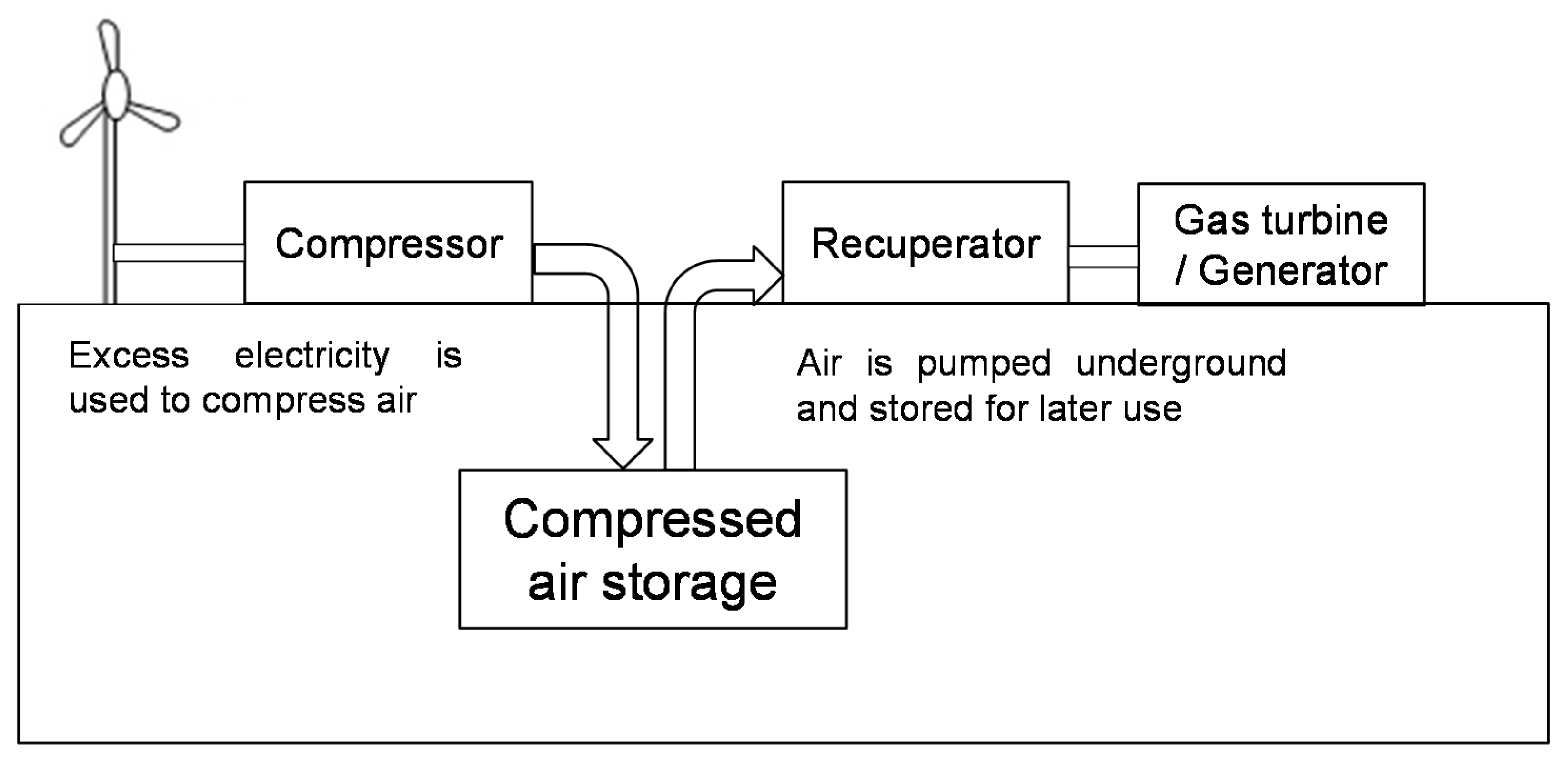
Energy produced from renewable sources and the need for geo-storage has gained wide attention during the past decades because of their low pollutant and greenhouse gas emissions. However, these sources have an uncontrollable nature and intermittently produce electricity. Due to this fact, the integration of renewable energy sources into the electricity power grid has become a new technical challenge in the energy sector. Compressed air energy storage (CAES) is one of the most promising forms of energy storage as a technology by which excess electricity is used to compress air and then inject it into subsurface caverns.
Figure 1 is a schematic representation of a CAES system. At excessive electricity demand, the stored air is recovered by decompressing the air (from the underground storage), used to burn a small amount of natural gas, and then generate the electricity from combustion using a gas turbine. Accordingly, it reduces greenhouse gases compared to the conventional system that mostly burns fossil fuels [
1].
CAES design methods are mainly decided by the geological formation. Potential sites for underground compressed air storage are typically grouped into three geological conditions: (1) salt caverns formed by solution and drying mining of rock salt deposits; (2) aquifers with water-bearing porous strata of permeable granular materials (e.g., rock or sand) or depleted gas or oil fields; and (3) caverns made by excavating sedimentary formations. The salt caverns used in two commercial-scale CAES projects (Huntorf in Gernmany since 1978 and Alabama in the USA since 1991) were economical due to the use of pre-existing formations, yet the high geological uncertainty (i.e., size and extent of the solution cavern) causes some difficulties in exploring salt formations at more than 400 m, controlling air leakage, and estimating the storage and production rate [
2,
3]. Geological features made of caprock, aquifer, and bedrock can be used for potential CAES facilities. However, the numerical analysis with field exploration shows that the aquifer site at Iowa in the USA fails to properly make the air bubble due to the unfavorable low permeability within the formation and the heterogeneous permeability of the reservoir exacerbates the situation due to the development of undesirable fingering and air passage [
4]. Contrary to two geological formations for CAES design, an excavated cavern in the sedimentary formation provides greater flexibility for site selection. It offers a closer distance between a wind farm and its storage and, thus, overcomes high transmission cost. Even though the excavated cavern could be more expensive to excavate compared to naturally-occurring reservoirs, it could be even more economical by reducing the transmission line cost [
5]. The excavated cavern could be located at a shallower depth if the unstable ground conditions after excavation can be stabilized through various support systems and injected air can be perfectly stored inside the lining. Indeed, the improvement around the cavern significantly reduces the additional cost and provides benefits of selecting the potential sites [
6,
7].
Construction of underground excavations in geological formations inevitably causes the redistribution of stress and arching, and possibly subsurface settlement. The development of a plastic zone induced by excavation depends on many parameters, including the excavation method, cavern geometry, surrounding geomaterial properties, and in situ stress conditions. Even though previous studies have investigated the extent of plastic zones and displacement convergence after excavation of underground structures [
8,
9], they fail to consider the long-term geomaterial behavior of underground structures subjected to mechanical repetitive loads inside storage, which gives rise to an emergent response that does not take place in monotonic loads usually considered in design. For example, the ground reaction curve that has been widely used in the design of underground structures only shows the radial displacement as the internal pressure inside the excavated tunnel is monotonically decreased. In this paper, we analyze the long-term response of underground compressed air energy storage subjected to cyclic internal stress variation. The numerical approach follows the hybrid model that combines the Modified Cam Clay model’s flow rule for the first load cycle and the polynomial-type strain accumulation functions involved terminal density and densification parameter. A numerical analysis attempts to capture the effect that the underground storage subjected to cyclic internal pressure has on the ground in terms of two parameters: surface settlement and inflection point. The findings of this work will be used in evaluating the mechanical stability and deciding construction methods and support systems for the long-term design of underground structures. In fact, the underground cavern at shallow depth requires not only settlement evolution for a large number of cycles, but also the air tightness of a concrete lining. The issue related to air leakage in a CAES system is beyond the scope of this paper because minimization of air leakage is important after deciding the concrete lining.
2. Fundamental Features: Long-Term Soil Responses
The response of geomaterials to cyclic loads can be divided into elastic deformation and permanent deformation. Accurate prediction of unlined energy storage is critically dependent on whether or not the surrounding soils experience progressive accumulation of plastic deformation. The analysis of long-term soil response on the unlined storage requires characterizing the plastic strain accumulation that depends on soil type and density, initial effective stress, cyclic stress amplitude and obliquity, and the number of cycles. Fundamental features are summarized herein.
(1) Volumetric Strain (Terminal Void Ratio)
Soils subjected to repetitive loading contract the volume and evolve towards terminal density. Dilative soils undergoes free-interlocking and expand the volume as they approach towards terminal density. Experimental study under repetitive
ko-loading shows most of volume contraction during the early cycles and the change in void ratio per cycle decreases with a number of loading cycles; terminal void ratio is visualized with the existence of “shoulders” after repetitive loads [
10].
(2) Shear Strain (Shakedown and Ratcheting)
The long-term soil response can converge to shakedown or ratcheting states [
11,
12,
13]. When cyclic loads cause a strain level below the elastic threshold strain, the soil mass recovers the original state upon unloading, and the dissipated energy per cycle remains constant thereafter (elastic shakedown). When the strain level exceeds the elastic threshold strain, the soil undergoes particle rearrangement and fabric changes; the dissipated energy decreases towards an asymptotic value until the soil reaches a stable deformation state, there is no additional accumulation of deformation, and the energy dissipation per cycle becomes constant (plastic shakedown). Plastic shear strain continues accumulating at a constant rate as the number of cycles,
N, increases.
(3) Components of Plastic Strain
Assuming the associative rule such as the Modified Cam Clay constitutive model, the cyclic strain flow rule defines the ratio of the shear strain to the volumetric strain. Each component is characterized by the stress obliquity and the stress state prior to cyclic loading (preloading). The volumetric and shear strain defined by the plastic potential function at the first load cycle shows different plastic strain accumulations according to an initial state of stress. For example, the soils under an isotropic state of stress mainly experience volumetric strain accumulation, and the strain increment per cycle goes to zero as the soils approach the terminal density, while initial deviatoric stress close to the critical state line mostly produce shear strain and its increment per cycle eventually becomes constant with a large number of cycles. Experimental studies show that the sequence of deviatoric stress amplitudes and hydrostatic preloading (up to
p’ = 300 kPa) have a minor effect on the change in the flow direction [
14], yet preloading up to the failure line produces more shear strain than volumetric strain [
15].
(4) Strain Accumulation Functions
Strain accumulation functions play crucial role in simulating unlined storage and defining the incremental stress from plastic strain per cycle. Previously suggested and new plastic accumulation models are generalized to include the plastic strain at the first cycle. The accumulation functions involve four parameters (exponential, polynomial, power, and hyperbolic models) and three parameters (power and log-linear model). More details refer to Ref. [
10].
3. Finite Element Analysis of CAES
A long-term response of unlined energy storage subjected to repetitive internal pressure can be simulated with a small number of parameters that involve empirical strain accumulation functions and constitutive models. This study employs the hybrid numerical scheme that considers the fundamental features of geomaterials under repetitive loads (as discussed in the previous section). In this section, we develop the module that can control the stress inside the storage, and then a numerical scheme within the framework of finite element method (ABAQUS 6.10 software) is implemented with a new empirical strain accumulation function.
(1) Internal Stress Module
The internal stress module is developed in this study and the numerical procedure is as follows:
The storage geometry is pre-defined.
The initial internal stress inside the storage is equivalent to the value of geostatic ko-stress.
The internal stress is gradually reduced at the same rate along the storage walls.
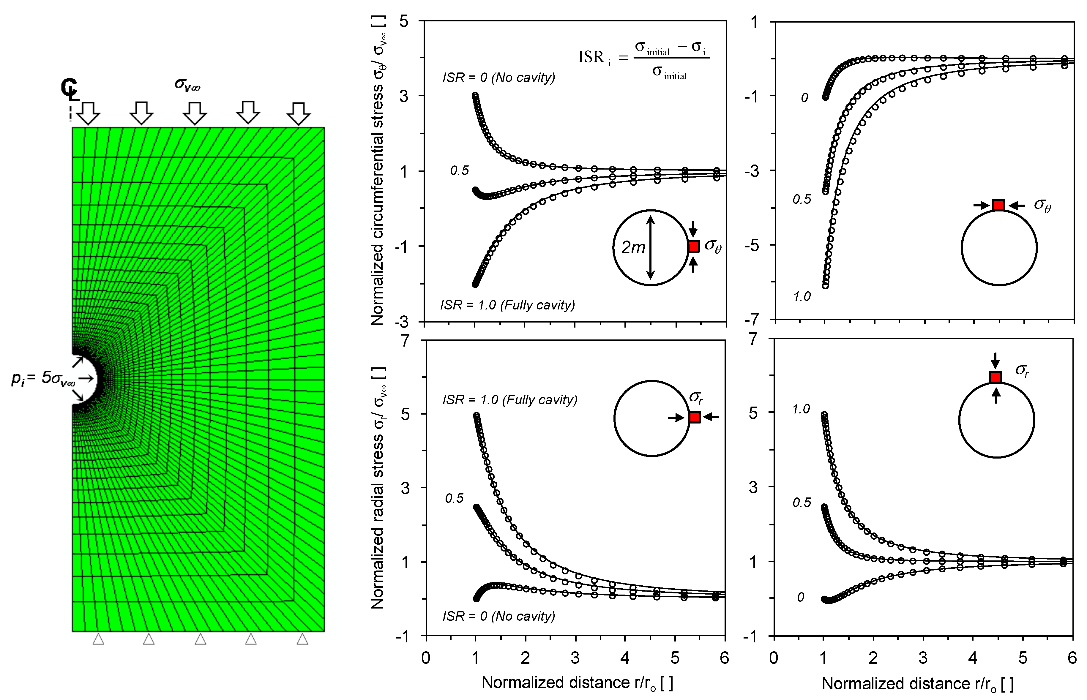
The code is verified for plane-strain conditions. The closed-form Kirsch solution applies to a circular storage of radius
a and internal stress
pi in a homogeneous isotropic, linear elastic medium subjected to far-field stresses. The stress distribution around the storage is:
where the radial
σr and circumferential
σθ stresses at distance r and at an angle
θ are a function of far-field stresses
σv∞ and
σh∞. An initial pressure
pint = 5
σv∞ is applied first and the internal stress is gradually reduced. A perfect match between the analytical and numerical predictions requires proper mesh refinement near the circle zone and implies higher computational costs [
16,
17].
Figure 2 shows the high agreement attained between the closed-form and numerical simulation for the stress relaxation module.
(2) Constitutive Models
Classical constitutive models with irreversible plastic potentials during unloading fail to accumulate strains induced by the number of load repetitions. The geostructures subjected to cyclic load can be simulated by tracking each cyclic response, yet the rate of strain accumulation is very small and, thus, the accumulation of numerical errors could become large compared to physically observed responses. Consequently, numerical modeling based on implicit calculation is limited to predict the long-term response [
18]. Additionally, the process of strain accumulation can be implemented with empirical approaches that fit experimental results with number of load cycles, yet their use is restricted to boundary value problems that need to satisfy force equilibrium and strain compatibility. Thus, semi-empirical numerical schemes have been developed by incorporating classical constitutive mode into strain accumulations functions [
19,
20,
21]. The wrong choice of strain accumulation function without a cutoff criterion (since accumulated volumetric strain
εvacc→∞ as
N→∞) requires higher computational cost to stop accumulating the plastic strain when cyclic strain drops below the elastic threshold strain. Ref. [
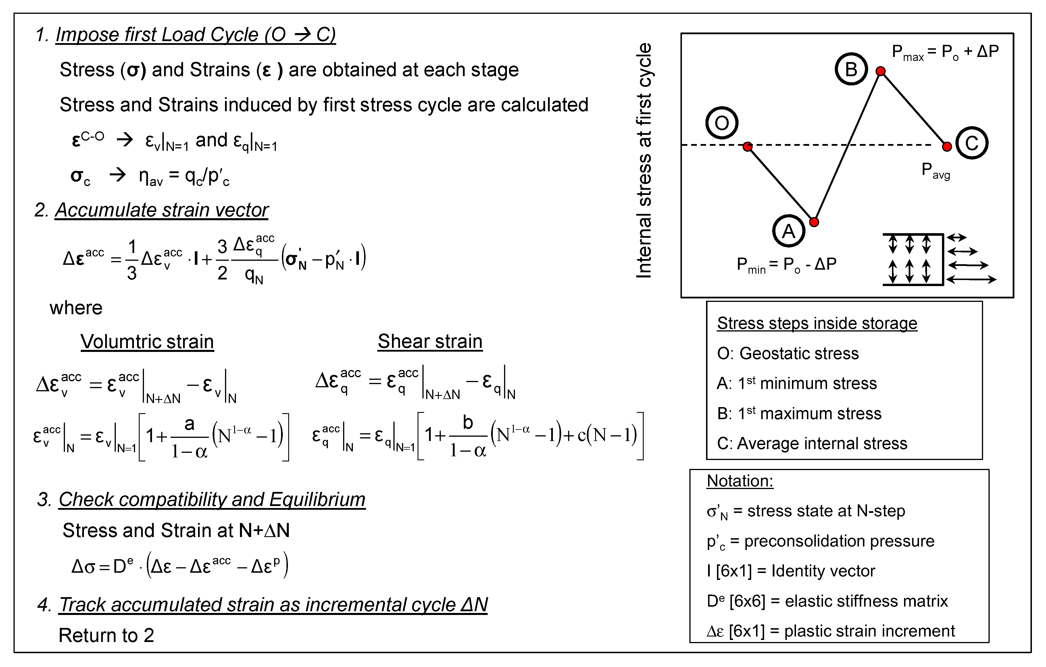
22] derived the polynomial function with four parameters and formulated in terms of volumetric strain and shear strain that allows constructing the accumulated strain vector from plasticity. The accumulation functions in a given load cycle
N can be expressed as:
where:
The parameters a, b, and c are constitutive parameters that reflect the effect of the average stress obliquity navg and critical friction angle M. In particular, the parameter c > 0 indicates the soil reaches ratcheting for i→∞. This study uses c = 0 for stable deformation of the surrounding soils around storage.
(3) Numerical Algorithm for the Semi-Empirical Scheme
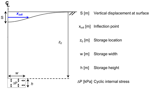
Figure 3 presents computation scheme for the average stress
Pavg at the first cycle. First, the initial stress fields defined by the geostatic stress are computed using the Modified Cam Clay model (Step O). Then, the cyclic internal stress Δ
P as the ratio of
Pavg to minimum or maximum internal stress is imposed around surface elements along the unlined storage at the first cycle (i.e., from state A to B). Finally, the imposed internal stress reaches geostatic stress condition. The stress and strain at the end of the first cycle are used to track the plastic volumetric and shear strain that accumulate during repetitive loading using the empirical functions (Equations (3) and (4)). Incremental strains at
N + Δ
N are imposed for each element, the stress increment is calculated from the accumulated strain vector Δ
εacc, and then numerical iteration is applied until the system can satisfy force equilibrium and compatibility. Indeed, the simple and robust hybrid scheme underscores the use of strains at the end of the first cycle that inherently embody the complicated effects induced by the initial effective stress, initial packing density, and the cyclic stress amplitude and direction.
(4) Model Calibration
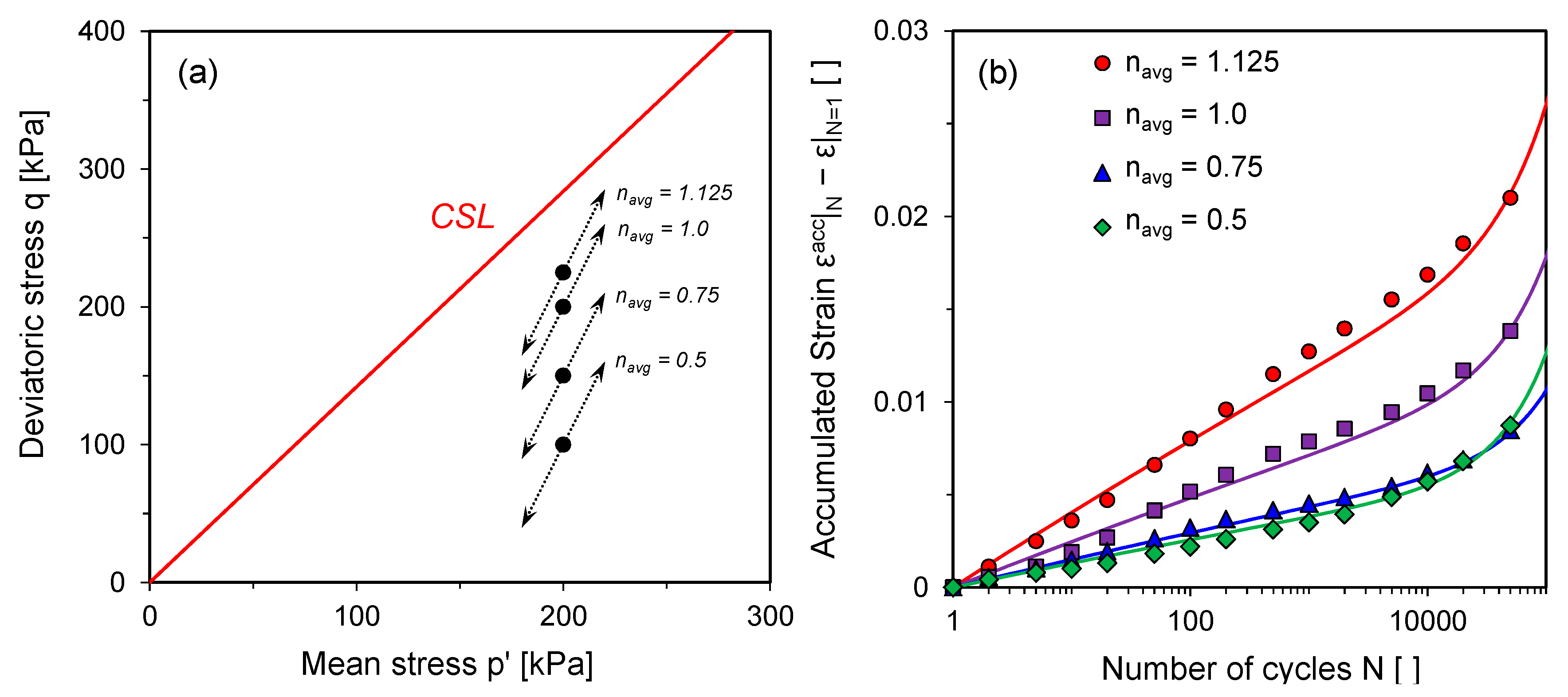
The model is calibrated using published triaxial test results for a quartzitic subangular sand. The constitutive parameters (
a and
b) are defined by formal inversion and summarized in
Table 1. Note that the strains induced by the first loading and the model parameters remain constant during numerical simulation).
Figure 4 shows the comparison between experimental data and numerical simulation for accumulates strain. The model tested with the triaxial strain conditions predicts the measured data with different rate of strain accumulation under four different stress obliquities [
23]. While the limited data is used to adjust numerical model, the comparisons confirm that the strain function with the relaxation of these parameters can be suitable for tracking the incremental plastic strains induced by different stress obliquity.
4. Simulation Results and Analyses
(1) Simulation Conditions
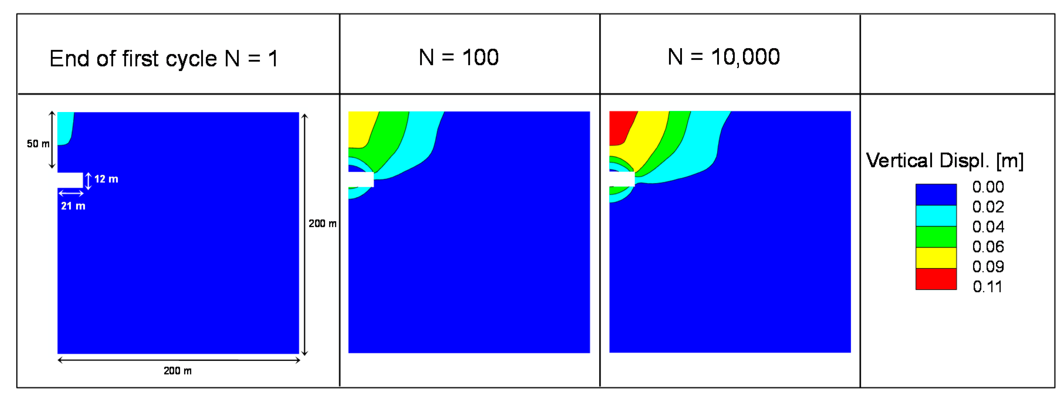
An unlined energy storage subjected to cyclic internal stress is simulated using plane strain conditions with four-node full integration elements. Vertical displacement is allowed on side boundaries, the bottom boundary is pinned, and the top surface is free. The lateral boundary effects are investigated during cycles. Vertical displacements (
Figure 5) and surface settlement (Figure 9) show that the far-field surface settlement profiles are zero at cycles
N = 1, 100, and 10,000. It is confirmed that the generated mesh and domain size has no effect on the physical response during the simulation.
(2) Simulation Results
A parametric study focuses on the ground response to cyclic internal stress within the unlined storage. The regular-smooth displacement fields in homogeneous media can be expressed with a few characteristic parameters (
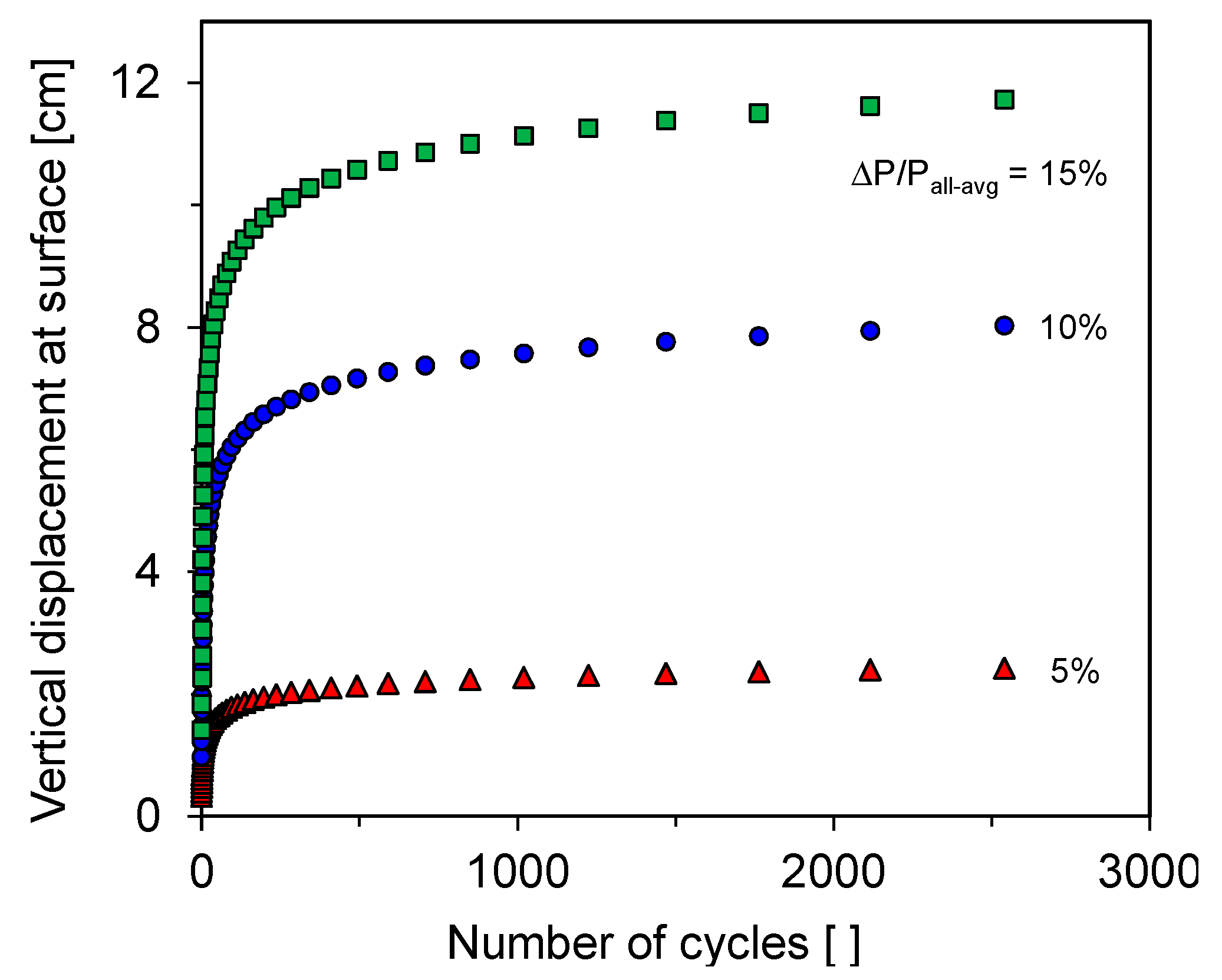
Table 2). An unlined energy storage is simulated by imposing a static stress followed by repetitive internal stress. The average static stress
Pavg inside the storage is defined by geostatic stress and cyclic stress amplitude Δ
P as 15% of
Pavg is applied on the surface elements inside the storage located at 50 m.
Figure 5 presents the redistribution of strain fields with number of cycles. The vertical displacement fields are regular-smooth after the large number of cycles. Compared to the vertical displacement at the first cycle, the cyclic stress produces additional vertical displacement of 7.5 cm after
N = 10,000 and wider settlement troughs. Cases are simulated by varying the cyclic internal stress amplitude. The vertical displacement at the surface increases with the cyclic stress amplitude, yet their incremental rate approaches towards an asymptotic value. The stable deformation state indicates that the ground surface response undergoes the plastic shakedown during cycles (
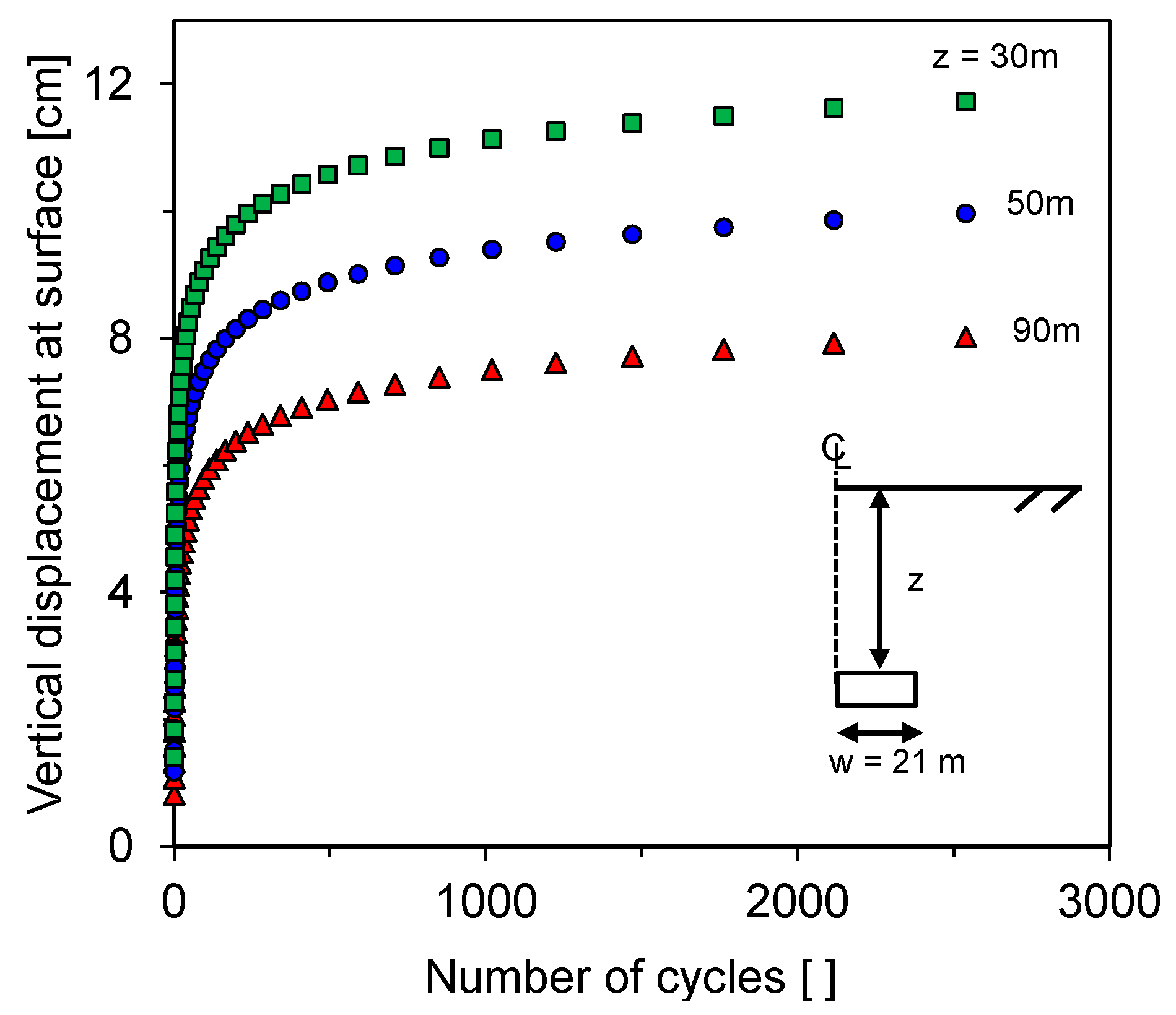
Figure 6). The storage location effect is investigated in
Figure 7. A shallower storage produces a larger surface settlement because it expedites the propagation of plastic deformation towards the ground surface that occurs from the elements around the storage. Even though the excavated storage at shallow depth permits improving the physical distance between wind farm and its storage, a shallower storage requires more support systems to resist the long-term repetitive loads.
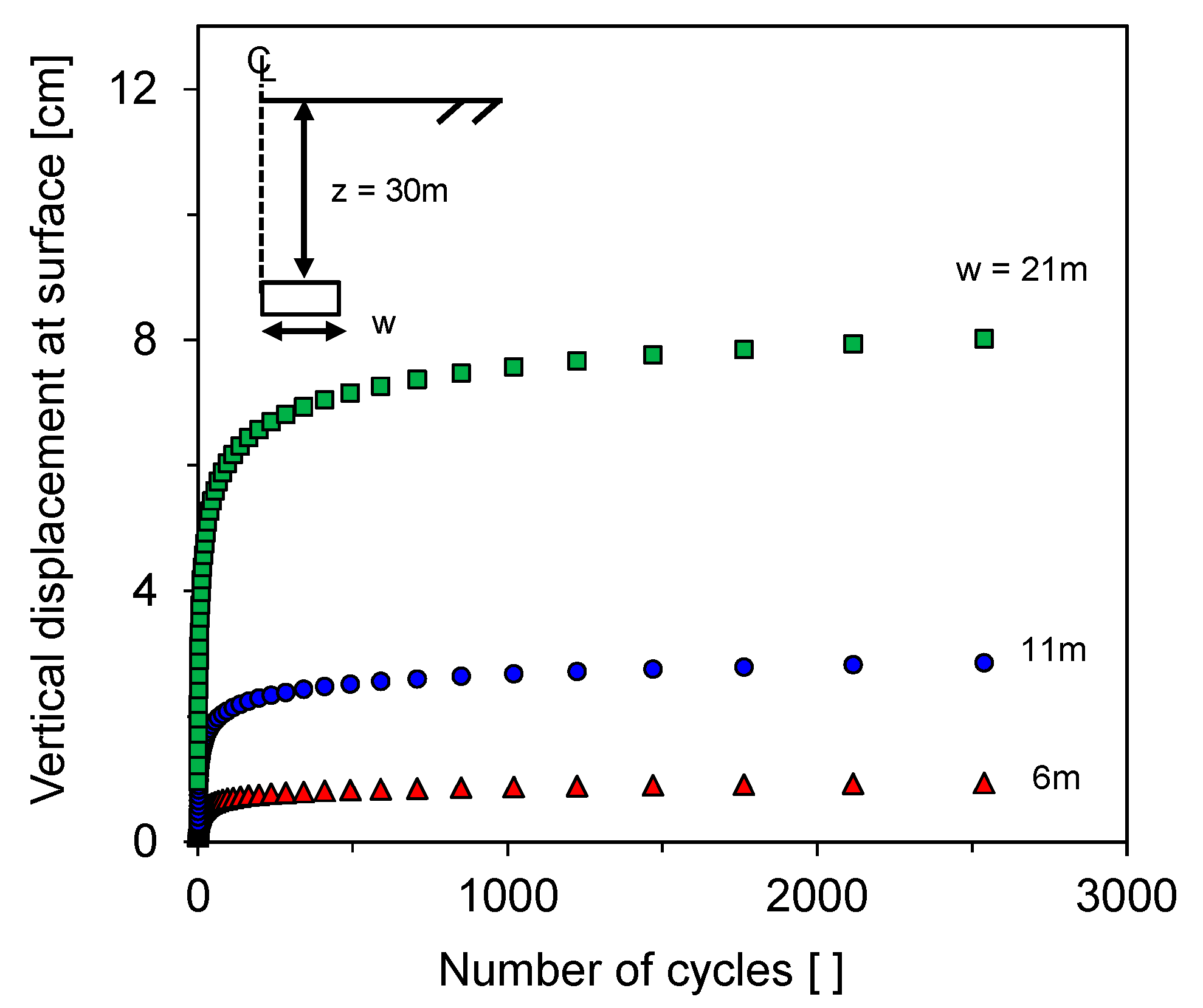
Figure 8 presents the effect of storage width on the evolution of vertical displacement during a cyclic stress along the storage. A larger storage volume propagates plastic strain on wider surface elements and accumulates more vertical displacement at the center.
(3) Analyses
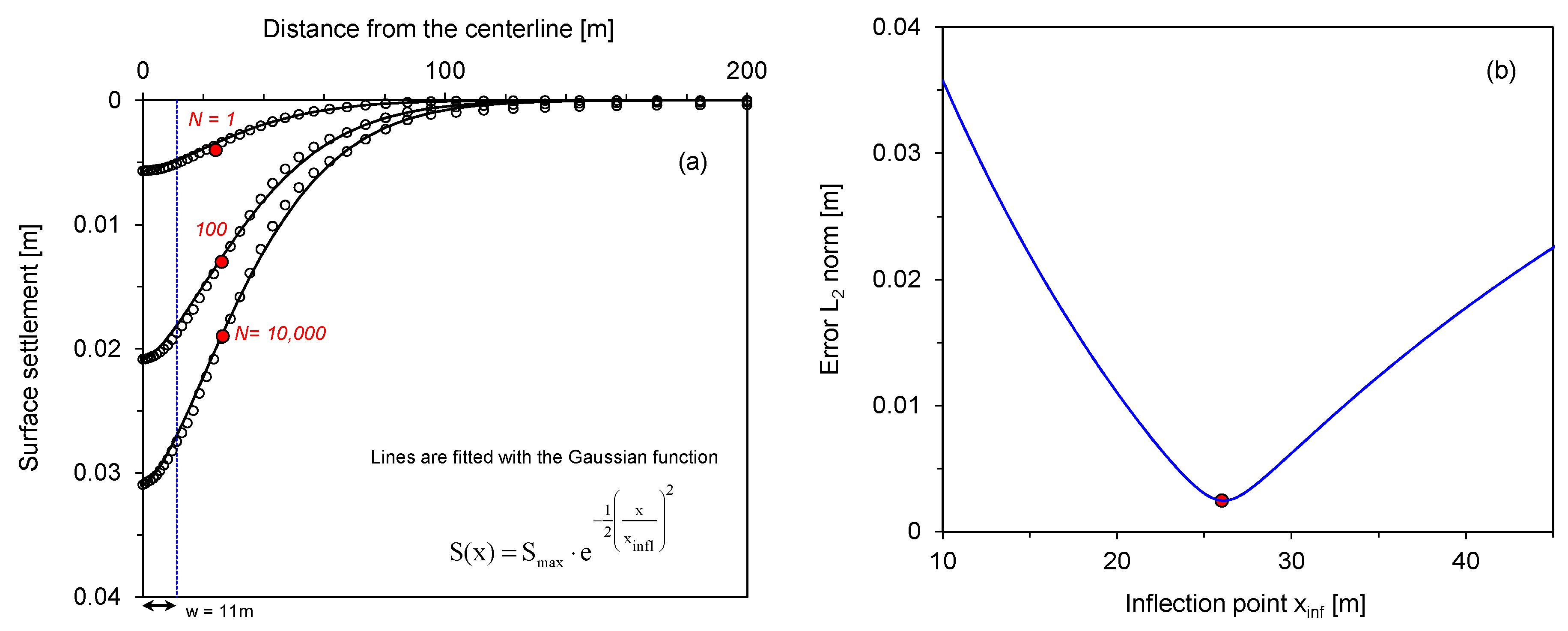
Ground settlement profiles without ground distortions are well matched by the Gaussian function. These are two degrees of freedom: the maximum settlement over the centerline
Smax and the transverse distance from the centerline to the inflection point
xinfl [
24]. Given regularity and smoothness of numerically-computed displacement fields, the settlement profile at
N cycles is fitted with a Gaussian function; the inferred distance to the inflection point
xinf and the maximum settlement
Smax. The error
ei between the predicted and numerically computed settlement at
N cycle is:
and it identifies the (
xinf,
Smax)
i = N that minimizes the square error norm:
Figure 9 shows the fitted surface profiles for the load cycles and slices of the error surface presenting the invertibility of the inflection point. The Gaussian model that has been widely used in tunnel engineering fits the surface settlement well during the cycles. The estimated inflection point has little variation at even a large number of cycles; instead, initially predefined geometry has pronounced effect on the inflection point. The observation suggests that the previous surface settlement models and empirical correlations could be used to predict the estimated displacement evolution for long-term response fields.
5. Discussion
The constitutive model and newly-proposed strain accumulation functions capture the fundamental features, such as the non-linear response to the initial stress and the first cycle and incremental strain rate at large number of cycles associated to terminal density. The previously-suggested accumulation functions require a cutoff criterion to stop accumulating the plastic strain when the cyclic strain drops below the elastic threshold strain or when the void ratio reaches the terminal void ratio. The criterion at every incremental cycle is checked with strains for all nodes. Accordingly, the computational complexity requires higher computation cost during a large number of cycles. Instead, the polynomial-type strain accumulation function involved the criterion itself avoid the cumbersome process and improves the algorithm efficiency.
The strain accumulation function needs four parameters (a, b, c, and α); the absence of ratcheting response removes the parameter c. A flexible model calibration can be achieved with the relaxation of these parameters. Additionally, the calibrated model can be tested against the evolution of the void ratio under a zero-lateral strain boundary condition.
The parametric study in this paper is only conducted with storage geometry and cyclic internal stress amplitude. The lack of experimental data limits the investigation of material properties’ effect on the long-term response to cyclic loading. Thus, it is recommended that experimental study be conducted with different conditions. For example, particle shape and grain size distribution cause different interparticle contacts and slippage and particle rearrangements in every cycle and, correspondingly, has a crucial effect on plastic strain accumulation in sands.
6. Conclusions
In this paper, we analyze the long-term response of unlined energy storage subjected to cyclic internal stress. The numerical approach follows the hybrid scheme that combined a mechanical constitutive model to extract stress and strains at the first cycle and polynomial-type strain accumulation functions to track the progressive accumulation of plastic deformation. In particular, the strain function includes the fundamental features that require simulating the long-term response of geomaterials: volumetric strain (terminal void ratio) and shear strain (shakedown and ratcheting), the strain accumulation rate, and stress obliquity.
A model is calibrated under triaxial strain boundary conditions by relaxing three model parameters. The internal stress module is developed to control the stress inside the storage and verified with the closed-form Kirsch solution. Then, the unlined storage subjected to cyclic internal stress is simulated with different storage geometries and stress amplitudes defined by geostatic stress. The simulations show that the ground surface experiences cumulative settlement and wider settlement troughs, yet their incremental rate approaches towards an asymptotic value. With regular and smooth displacement fields for even large numbers of cycles, the inflection point is estimated with the previous surface settlement model. The analysis shows that the estimated inflection point has little variation at even large numbers of cycles, yet predefined geometry has a greater effect on the inflection point. Even though the material properties’ effect is not investigated in this paper due to the lack of experimental data, the observations could be used to provide the decisions concerning construction methods and support systems when shallow storage will be constructed to improve the distance between a wind farm and storage.


