Article

Mechanical Characteristics of Superhigh-Water Content Material Concretion and Its Application in Longwall Backfilling

1
School of Mines, China University of Mining & Technology, Xuzhou 221116, China
2
The Jiangsu Laboratory of Mining-Induced Seismicity Monitoring, China University of Mining & Technology, Xuzhou 221116, China
3
Key Laboratory of Deep Coal Resource Mining, China University of Mining & Technology, Xuzhou 221116, China
4
State Key Laboratory of Coal Resources and Safe Mining, China University of Mining & Technology, Xuzhou 221116, China
5
Jizhong Energy Handan Mining Industry Group, Handan 056002, China
6
School of Mining Engineering, University of New South Wales, Sydney, NSW 2052, Australia
7
School of Mines, Guizhou Institute of Technology, Guiyang 550003, China
*
Author to whom correspondence should be addressed.
Energies 2017, 10(10), 1592; https://doi.org/10.3390/en10101592
Submission received: 19 September 2017 / Revised: 1 October 2017 / Accepted: 9 October 2017 / Published: 13 October 2017
(This article belongs to the Section L: Energy Sources)

Abstract

:
Superhigh-water content material (SCM) has been widely utilized for goaf backfilling, grouting, and fire prevention and extinguishing. In this paper, the engineering mechanical characteristics of superhigh-water content material concretion (SCMC) were studied for two types of backfilling technologies in longwall mining—open-type and pocket-type backfilling. The mechanical properties and responses of the SCMC were assessed under different cementation states, varying loading conditions and at different scales. The results indicate that: (1) the compressive and tensile strengths of SCMC specimens in different cementation states increase as the curing time increases—the SCMC formed by a mixture of SCM and gangues has higher strength than that of pure SCM; (2) the SCMC is under different loading and confinement conditions when different backfilling technologies is applied; however the strength of SCMC increases with curing time and decreases with water volume percentage; and (3) large-size specimens of pure SCMC enter into an accelerated creep state at a leveled load of 1.4 MPa. The effects of SCM backfilling on subsidence control has been verified by field applications. The results presented in this paper can provide data support for the optimization of backfill mining technology using SCM, as well as for the design of hydraulic supports parameters at longwall faces.

1. Introduction

A critical factor in controlling the mining-induced subsidence of overlying strata in mined-out areas is the performance of backfilling material [1,2]. The current backfilling technologies can be classified into three major groups depending on the material used—dry backfill, water-sand backfill, and cemented paste backfill (CPB). Cemented paste backfill is most widely used due to its high strength, fast backfill speed, and simple application technique. A number of studies have been conducted on CPB that focus on three main areas:
(1)
Various backfilling materials have been developed based on CPB. In the early 1980s, a mixed cementation material was developed which was called Aquapak that can be solidified with a volume ratio of water up to 85%. This work laid the foundation for subsequent research and development of high-water backfilling materials [3,4]. Sun et al. [5] developed a high-water rapid-setting material with a water volume ratio up to 90%. By improving the sand-soil solidifying backfilling material, they developed a sialite paste-like backfilling material along with another material called Ningtaike-A. Feng et al. [6] developed a type of superhigh-water backfilling material that features a high water content, controllable strength and setting time, as well as sound fluidity of single slurry.
(2)
Systematic studies have been carried out on the mechanical properties and influencing factors of CPB. Arioglu [7] proposed a formula for calculating the strength of CPB based on the field conditions and the characteristics of CPB. Thomas model is designed to predict the vertical stress at the bottom of CPB [8]. Cui and Fall [9] proposed an evolution elasto-plastic model for CPB. Fall et al. [10] established a water conductivity function model for CPB. Yi et al. [11] improved the ductility of CPB by adding in polypropylene fiber. Klein, Simon, and Hughes et al. used shear wave velocity tests [12], in-situ tests [13], and electromagnetic wave detection [14], to analyse the compressive strength [15], hydration process, and curing time of CPB that contained different cementing agents [16]. Sheng Huang, Fall M., and Nasir O. studied the effects of strain rate, curing time, and mixture ratio on the compressive strength of CPB [17,18,19].
(3)
Experimental studies have been conducted on the fundamental physical properties of CPB. Ghirian and Fall [20] systematically studied the changes in the physical characteristics of CPB including thermal conductivity, pore-water pressure, shear strength, and microstructure under multi-field coupling effect at early curing times. Celestin and Fall [21] and Ouellet et al. [22] analysed the influential factors of the thermal conductivity of CPB and the evolution process of its microstructure, respectively; Ercikdi et al. [23] and Yilmaz et al. [24] proposed a method of quickly evaluating compressive strength using ultrasonic waves that used statistical analysis of the velocity of ultrasonic waves through the CPB under various water-cement ratios and sizes.
Extensive studies on the effect of superhigh-water content material (SCM) in controlling overlying strata in goaf area during backfilling have been conducted, resulting in the development of a technique for assuring the filling rate of SCM, as well as a roof control technology based on the relationship between supports and rocks during longwall goaf filling using SCM [25]. During backfilling of SCM, the cementation states, load conditions and size of superhigh-water content material concretion (SCMC) all change with the roof caving, backfilling face advancing and the filling range increasing and the mechanical properties of SCMC change accordingly. Recent studies have focused on the fundamental properties of SCMC, such as the compressive strength and volume strain of SCMC under different water volume and weathering time. But few involve comprehensive studies on the effects of backfilling technologies, cementation states, confinement conditions, and size on the engineering mechanical properties of SCMC. In this paper, the strength changes and the scale effect of SCMC were explored under various cementation states and load conditions, taking into consideration the backfilling process of both open-type and pocket-type technologies. The experimental results and stability of SCMC are verified through the field application. This study aims to provide guidance on optimizing backfilling techniques and to offer design parameters for using SCM.

2. Mechanical Behaviour of the Backfilled SCMC

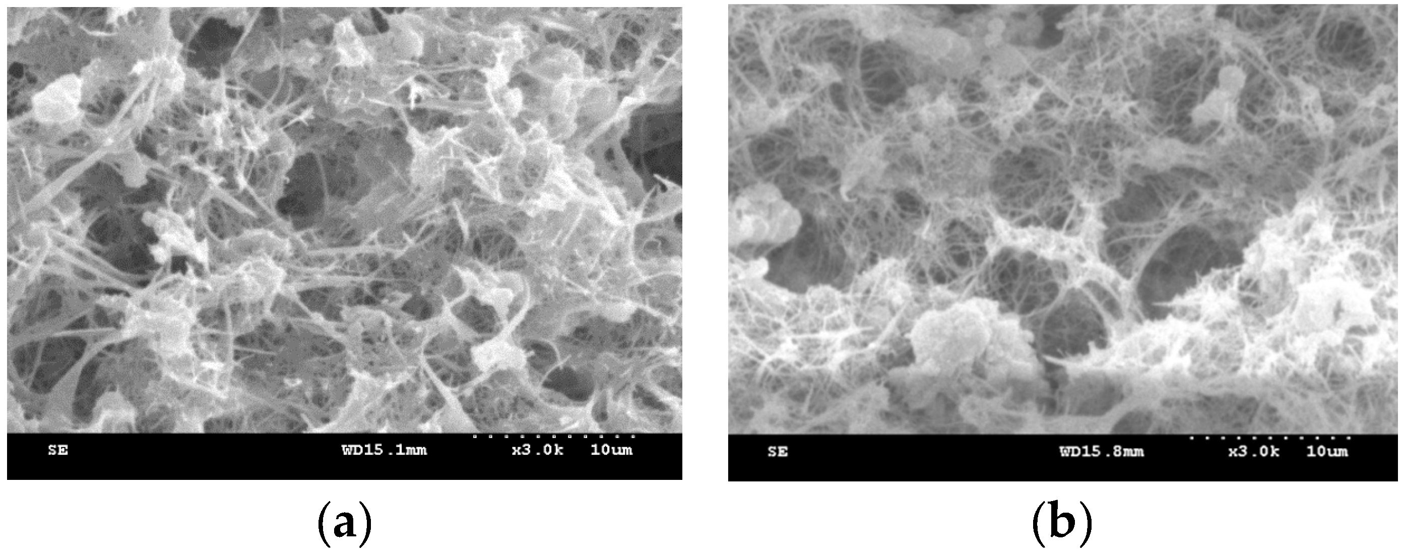
2.1. The Micro-Characteristics of SCMC

SCMC was scanned using a scanning electron microscope (SEM) to better understand the characteristics at the micro scale. The SCMC samples were cured for 14 days at 19 °C. The results show that the concretion contains meshy and acicular ettringite, which are the main ingredients—aluminagel and other substances that the characteristics is dispersed, nonfixiform and flocculent. The SEM photos (amplification 3000 times) of the concretion with different water volume percentage are showed in Figure 1a,b.
Figure 1 shows that the form of ettringite will change with the water volume. The acicular and rod-shaped structure of ettrigite becomes slender as water volume increases. It is a very thin mesh-like structure when the water volume is at 97%. The research shows that the main reason why the superhigh-water content material concretion (SCMC) has high water holding capacity is because of the presence of the porous structure as the ettringite mutual crisscrosses with ettringite and the gel material.

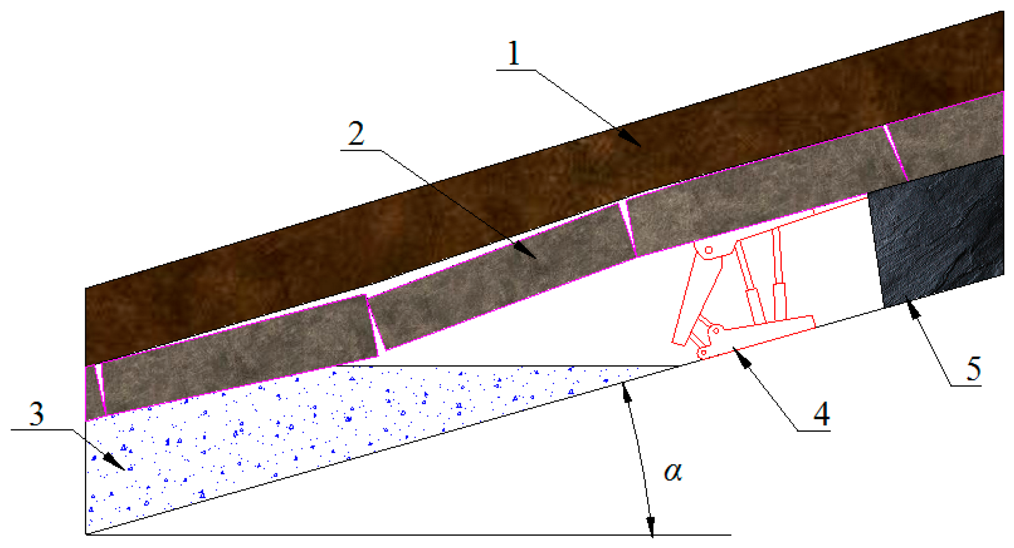
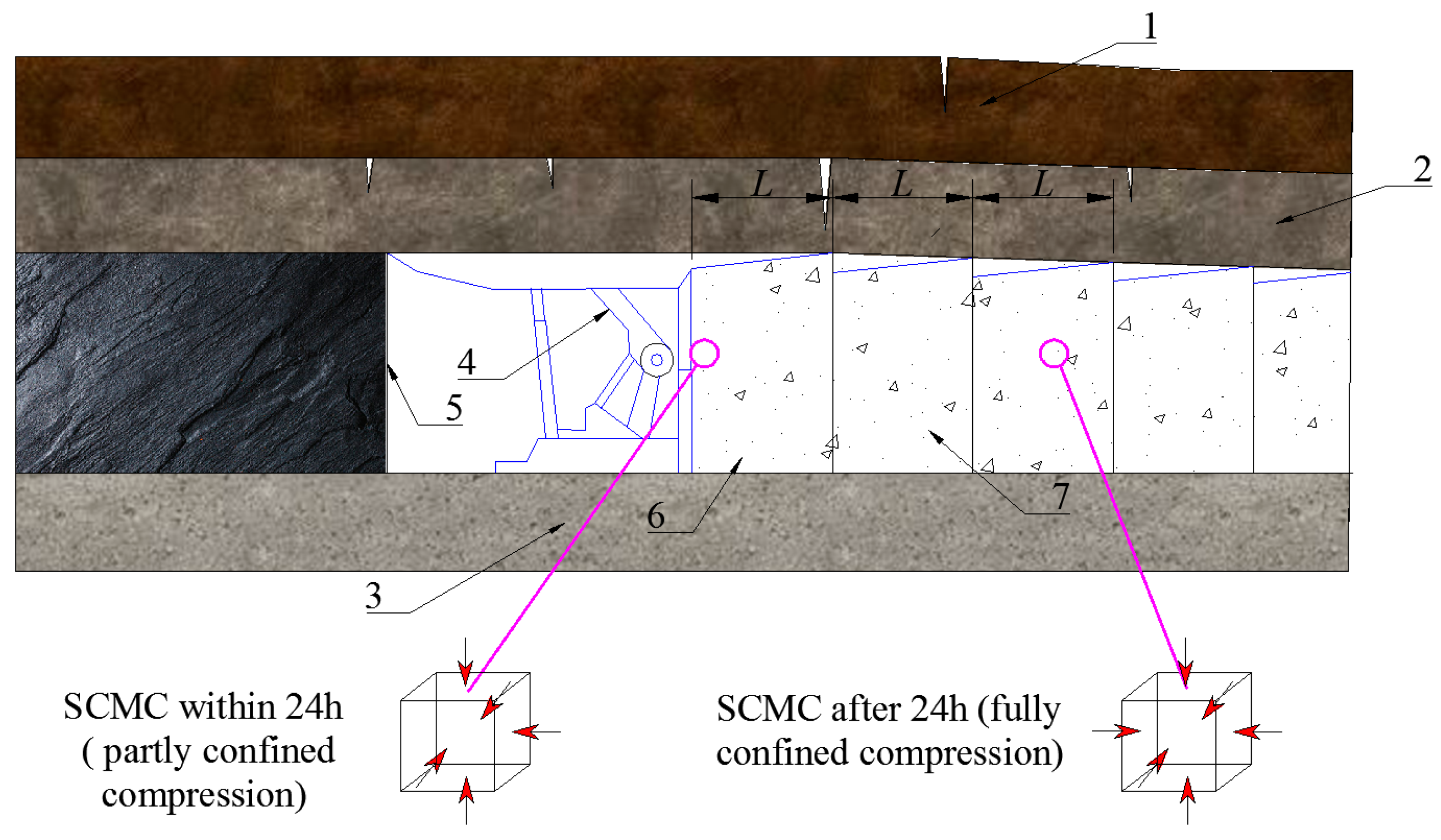
2.2. Engineering State of SCMC Using Open-Type Backfilling

Open-type backfilling using superhigh-water content (SCM) is applied for mining upwards the inclined seams, and when the working face has advanced for an appropriate distance the goaf is backfilled. Of note is that the caving of the overlying strata is not interfered during the backfilling process. This method ensures that there is no interference between backfilling and mining, which simplifies the technological process. A schematic diagram of an open-type backfilling of SCM is shown in Figure 2.
In practice, SCM has varying cementation states due to the difference in backfilling timing, strata characteristic and caving behaviours. When the roof is relatively intact, the SCMC are primarily pure superhigh-water cemented paste; if the roof is fractured, the SCMC will be a mixture of SCM and caved rocks. Based on relative position between the caved strata in the goaf and backfilled material, the SCMC can be preliminarily classified into the following four types (as shown in Figure 3): Type I—pure SCMC; Type II—substructure consisting of a mixture of SCM and gangues and superstructure consisting of a pure SCMC; Type III—substructure consisting of a pure SCMC and superstructure consisting of a mixture of SCM and gangues; and Type IV—the whole structure consisting of a mixture of SCM and gangues.

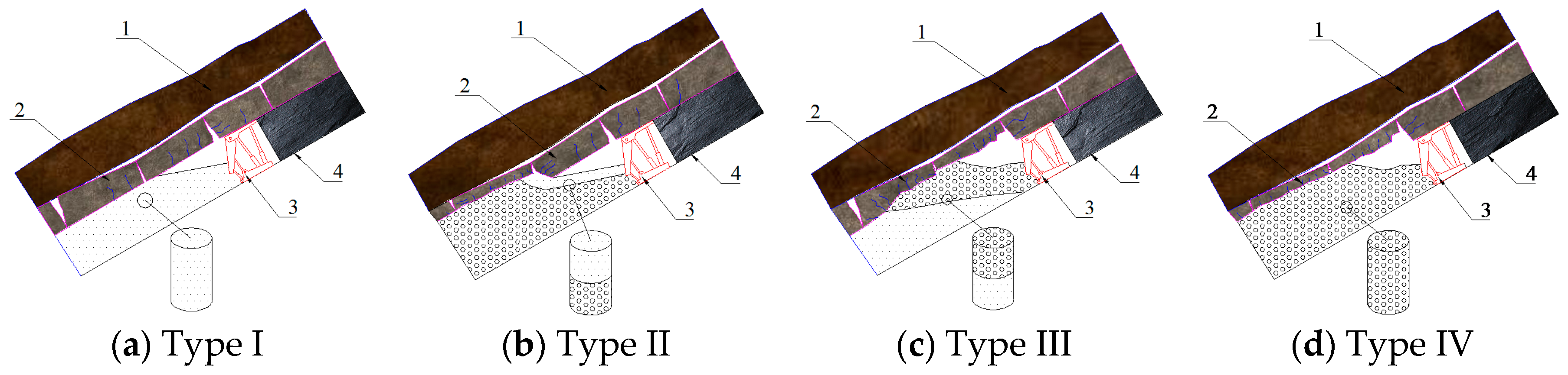
2.3. Stress State of SCMC Using Pocket-Type Backfilling

Pocket-type backfilling using SCM is a very simple process. The prepared paste fluid is delivered by pipelines to a mixer that is close to the filling working face; after being mixed, the paste is delivered to the pockets that are pre-arranged inside the goaf. After solidification inside the pockets, the paste fluid acts as a support to the overlying strata. This method has a large scope of applicability as it is convenient to install the pockets and the pockets can impose restrictions on the cemented paste. A schematic diagram of the pocket-type backfilling of SCM is shown in Figure 4.
The pocket-type backfilling is commonly used for the working scheme with 3 shifts per day. A work flow is adopted in which each backfilling should be conducted after two cutting cycles. Within the first 24 h (in the early stage of backfilling), the SCMC is subjected to relatively small loading from the roof and its displacement towards left or right is restricted. There is no confinement in front of the SCMC in the presence of the working face, which gives an unconfined space for the SCMC. Within 24 h, the SCMC is in a partly confined state, specifically subjected to compression from all directions except for the direction of the working face. After 24 h (the later stage of backfilling), with the new SCMC filling the goaf and hardening quickly, the previous SCMC is also confined in the forward direction along with the sagging of the roof, the SCMC starts to bear a load gradually, which subjects the SCMC to completely confined compression.

3. Laboratory Testing

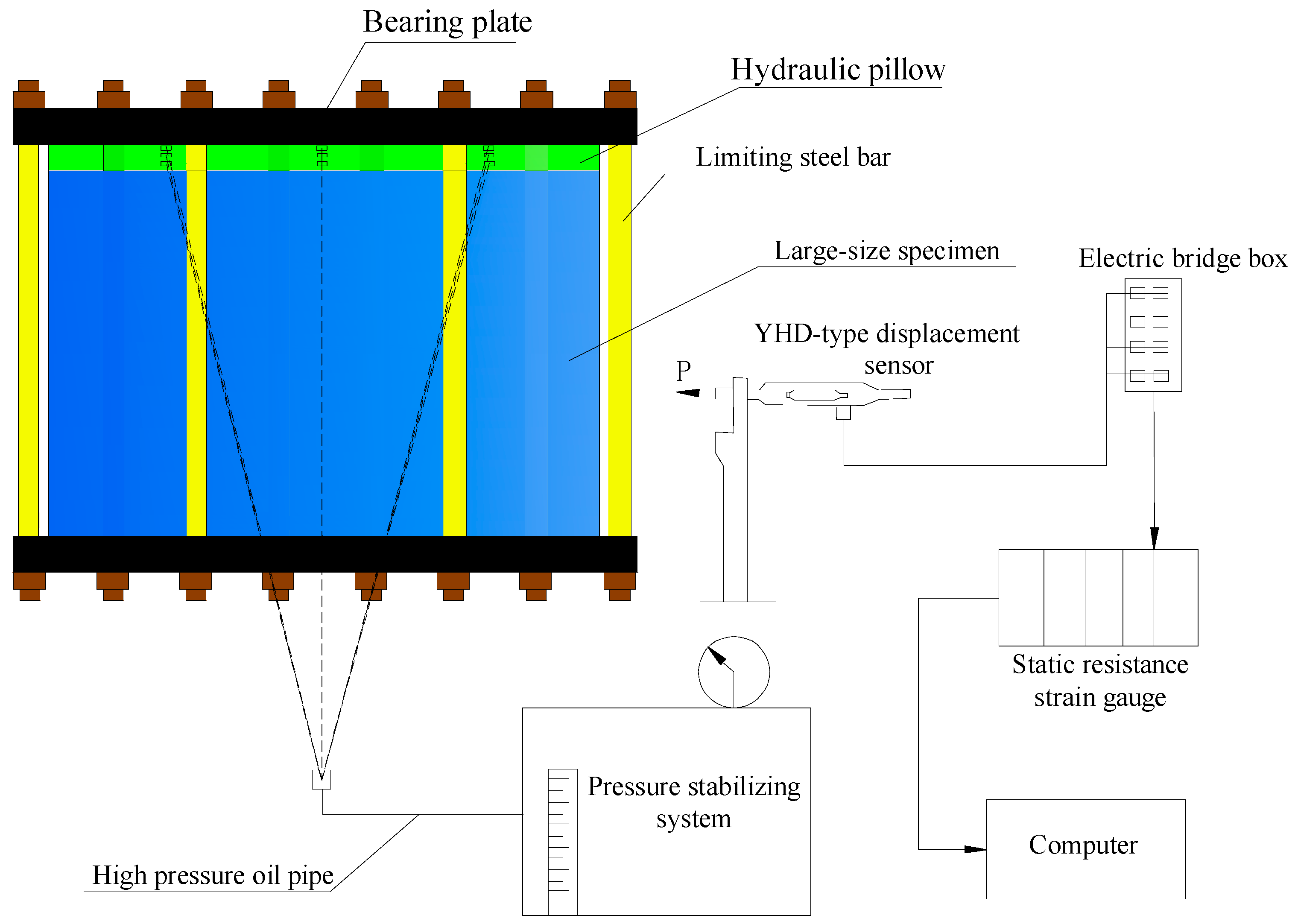
3.1. Experiments Facilities and System Setups

(1) Mold and Curing Box
In this study, a cylindrical and cuboid molds are available for making SCMC specimens. The cylindrical mold has an outer diameter of 70 mm, an inner diameter of 50 mm, and a height of 100 mm; while the cuboid mold has a size of 4 × 100 mm, with both height and width of 100 mm, which can make four cube specimens at one time.
In order to simulate the field moist environment, the curing box is used to adjust the temperature and humidity and cure the specimens.
(2) Large-size Mechanical Properties Testing System for SCMC
To study the scale effect of SCMC, a 10,000 kN large-size testing system (1500 mm × 600 mm × 900 mm) was developed and used for this research. The system mainly consists of limiting steel bars, bearing plates, hydraulic pillows, stress stabilizing systems, displacement sensors, and static resistance strain gauge, as shown in Figure 5.

3.2. Samples Preparation

(1) Experimental Materials
The SCM is primarily made from materials A and B. Material A is obtained by refining bauxite and gypsum, while material B by grinding gypsum and lime. During the process, a small amount of composite super-retarding dispersing agent (material AA) is added into material A; and a small amount of composite accelerator (material BB) is added into material B. The volume ratio of materials A and AA to materials B and BB is 1:1.
The materials for the SCMC used in the experiments came from the backfilling station of Taoyi Coal Mine of Handan Mining Group; the water came from tap water in the laboratory (water temperature being 18 °C); and the gangue was obtained from the longwall panel and was crushed into required particle sizes.
(2) Standard Samples
Four types of SCMC specimens were prepared in this study. After curing, mechanical property tests were conducted to analyse the strength characteristics of the four types of SCMC at different curing times.
Cylinder molds were used to prepare specimens for four types of SCMC. In the mixture the mass ratio of gangue to superhigh–water materials was 1:5 and water in the SCMC had a volume percentage of up to 95%. Standard specifications were used with the diameter to 50 mm for the compression and tension test. The specimens were placed inside the curing box at 20 °C and humidity of 99%, which were cured for 2 h, 1 day, 2 days, 3 days, 4 days, and 5 days respectively. A set of four specimens were prepared for each type of SCMC at the different curing durations, for the three types of tests.
(3) Specimens for Confined Compression Tests
In order to understand the mechanical property changes that the SCMC goes through after being filled in the goaf, it is necessary to conduct both partly confined and completely confined compression tests on the SCMC based on the loading characteristics in the goaf. For this purpose, two types of specimens were prepared for two different stress states:
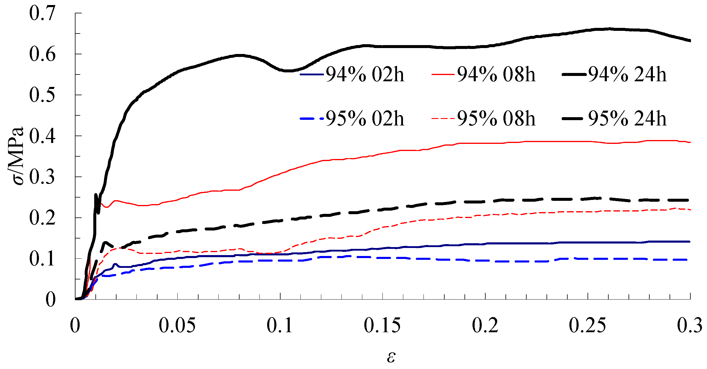
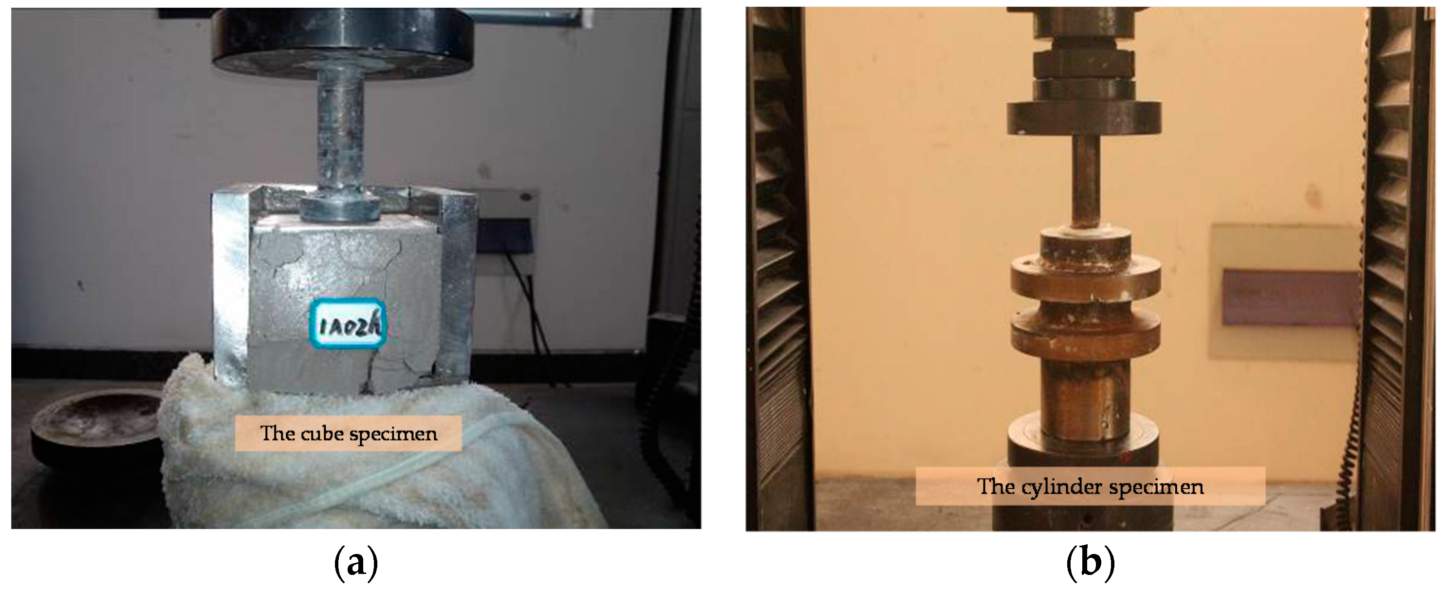
  • Specimens subject to partly confined compression stress (early stage of backfilling, within 24 h): 324 cube specimens (100 × 100 × 100 mm), one-half with a water volume percentage of 95% and one half with a water volume percentage of 94%, were prepared and cured for 2 h, 8 h, and 24 h.
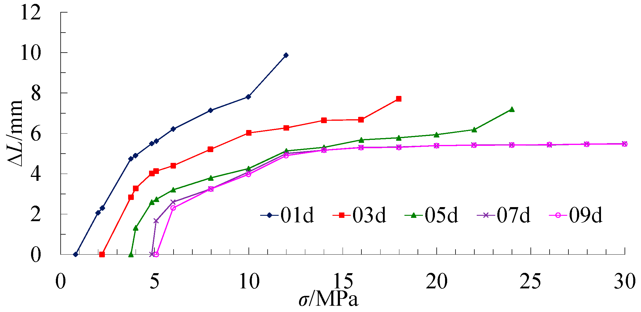
  • Specimens subject to completely confined compression stress (late stage of backfilling, after 24 h): 160 cylinder specimens (Φ = 50 mm, h = 100 mm) in 20 groups, one-half with a water volume percentage of 95% and one-half with a water volume percentage of 94%, were prepared and cured for 1 day, 3 days, 5 days, 7 days, 9 days, 15 days, 19 days, and 20 days.
(4) Large-size Specimen
Large-size specimen with dimensions of 1500 mm × 600 mm × 900 mm, and with a water volume ratio of 95%, was prepared using designed steel formwork. A handheld vibrating rod was used for vibration and tamping. The specimen was cured for 7 days in a sealed environment.

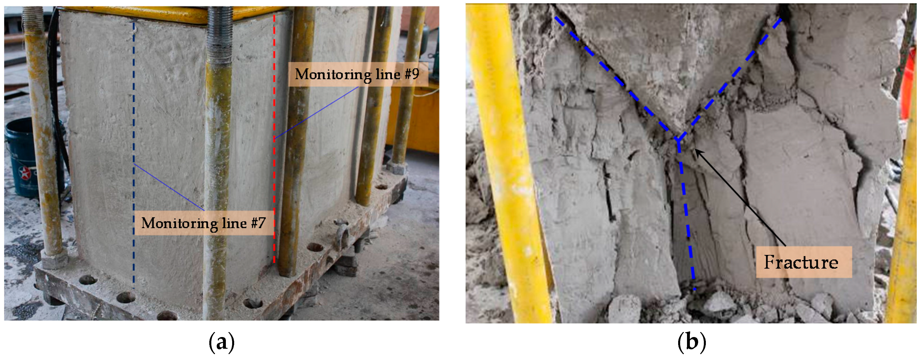
3.3. Testing Method and Process

(1) Mechanical Property Test of Standard Specimens
MTS815.02 (SHT5305, Mechanical Testing and Simulation Systems Corporation, Minneapolis, MN, USA) testing system is used to apply a load onto the four types of specimens until the specimens are yielded. The data collected automatically by the system is used to analyse the strength of the specimens.
(2) Mechanical Property Test of Confined Samples
After curing, the specimens are placed into the compression molds and the loading rate of the MTS815.02 testing system is set at 70 N/s to conduct confined compression tests. Compressive force is applied onto the specimens until they are fully damaged, and the test data is exported to analyse the strength of the specimens. This test process is shown in Figure 6.
(3) Creep Property Test of Large-Size Specimen
The large-size mechanical property testing system is used to conduct a compression test on the large-size specimen, in order to study it creep property and scale effect.
The stress stabilizing system applies a load at a rate of 0.1 MPa per level for a time duration of 120 min for each level. A YHD100-type displacement sensor (YHD-100, DaHao Electronic Co., Ltd., Shenzhen, China) is used to monitor lateral deformation, and fixed scale strips are used to monitor axial deformation. The displacement sensor is connected to a TS3890A static resistance strain gauge in the form of a half-bridge connection, which collects data at intervals of 6 s and stores data in the database. With regards to the monitoring setup, monitoring lines #1, #2, #3, #4, #5, and #6 fall in a horizontal direction; and monitoring lines #7, #8, #9, #10, #11, and #12 are in an axial direction.
A large-size mechanical properties testing system is used to apply a load on to the large-size specimen in accordance with the loading plan. The loading and destruction process of large-size specimens is shown in Figure 7.

4. Analysis of Experiments Results

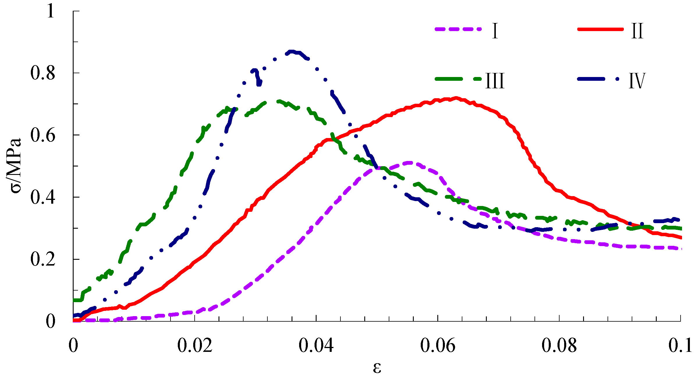
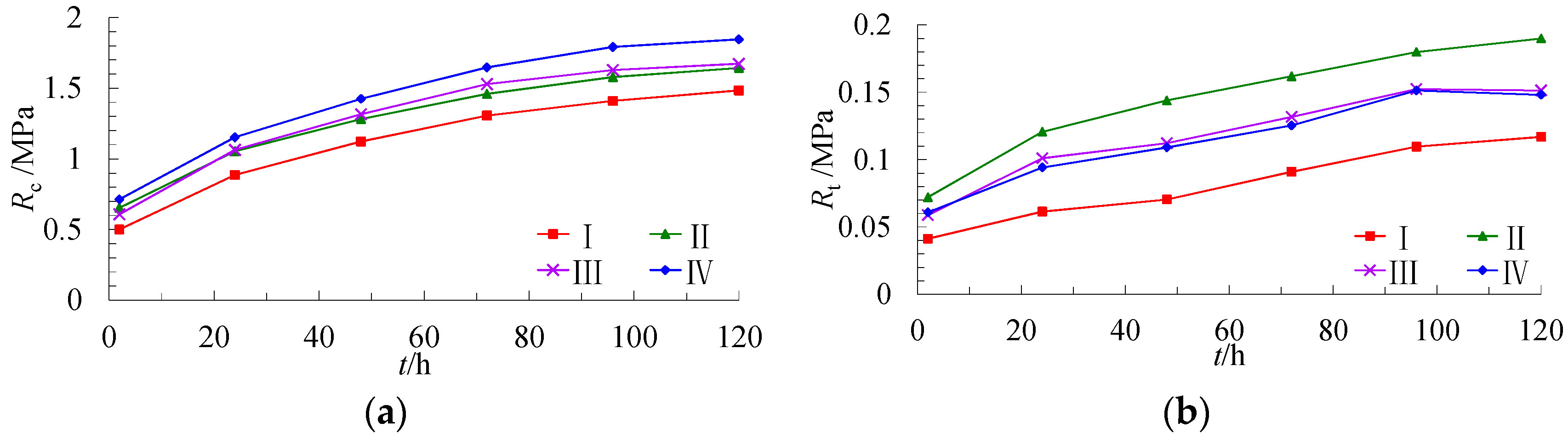
4.1. Mechanical Properties of SCMC with Different Cementation States

The compressive strength characteristics of four types of specimens at the same curing time, as well as relationships between strength and curing time of the specimens were analysed in this section.
(1) Compressive Strength Characteristics of Specimens at the Same Setting Time
Figure 8 shows compressive strength change characteristics of the four types of specimens after the same curing time of 24 h.
Figure 8 indicates the type IV specimens have the highest ultimate strength, and type-II and type-III specimens have similar ultimate strength, respectively, about 82.76% and 80.46% of type IV specimens. The ultimate strength of type I specimens is the lowest, about 58.62% of type IV specimens. The stress within the four types specimens at five stages during the loading process: original pore compaction stage, linear elastic stage, elastoplastic transition stage, plastic stage, and post-failure stage. The original pore compaction stage of type-I specimens is the longest, and the type IV specimens quickly into the linear elastic stage and reach the ultimate strength.
(2) Strength Characteristics at Different Curing Times
Figure 9 shows the time history curves of the strength of the four types of specimens. The strength of the four types of specimen increases as curing time goes on, and meanwhile, the increment decreases gradually. The type-IV specimens have the highest compressive strength, followed by type-II and type-III specimens, which have similar compressive strength; compressive strength of type I specimens is the lowest, about 20% lower than that of type IV specimens. Type II specimens have the highest tensile strength-about 40% higher than type-I specimens. None of the four types of specimens has a particularly high tensile strength; in all samples, the tensile strength is only 1/10 of the compressive strength.

4.2. Deformation Behaviour of SCMC under Confined Compression

Analysis was carried out on the strain (ε) characteristics of specimens under different confined compression conditions. The results are as follows:
(1) Specimens Subject to Partly Confined Compression
The stress-stain curves of specimens subjected to partly confined compression (within 24 h after backfilling) are depicted in Figure 10, which shows that the strength of the specimens increases with curing time; after the same curing time, the strength of the specimens is inversely related to the water volume percentage. Within 24 h of curing time, the maximum strength of the specimens is 0.65 MPa at a water volume percentage of 94%, and 0.24 MPa at a water volume percentage of 95%.
(2) Specimens Subject to Completely Confined Compression
a. Deformation behaviour of specimens under different load conditions
Different loads were applied to the specimens to simulate changes at different burial depths and to study the deformation behaviour of specimens at different curing durations. As curing time elapses, the specimens became less deformed, and there is a smaller increment in deformation—after 7 days, the deformation of the specimens stabilized and was maintained at 5.2 mm, with a compression ratio of 5.2%.
Different loads were applied to the specimens to simulate changes at different burial depths and to study the deformation behaviour of specimens at different curing durations. Figure 11 depicts the deformation curves of specimens under these conditions and indicates that as curing time elapses, the specimens became less deformed and there is a smaller increment in deformation—after 7 days, the deformation of the specimens stabilized and maintained at 5.2 mm, with a compression ratio of 5.2%.
b. Critical Deformation Load Characteristics of Specimens
After the specimens were subjected to completely confined compression—along with increases of load—water oozed from the specimens. The load under which water begins to ooze from the specimens is considered as the critical deformation load. Statistical analyses were performed on the test data in order to determine the critical deformation load. The curing time curves of the specimens are shown in Figure 12.
It is shown that, at higher water volume percentage, the critical deformation load is lower. Prior to 7 days, the critical deformation load of specimens increases rapidly; after 7 days, it increases at a lower amplitude, and remains at about 14.3 MPa (water volume percentage of 94%) and 10 MPa (water volume percentage of 95%).

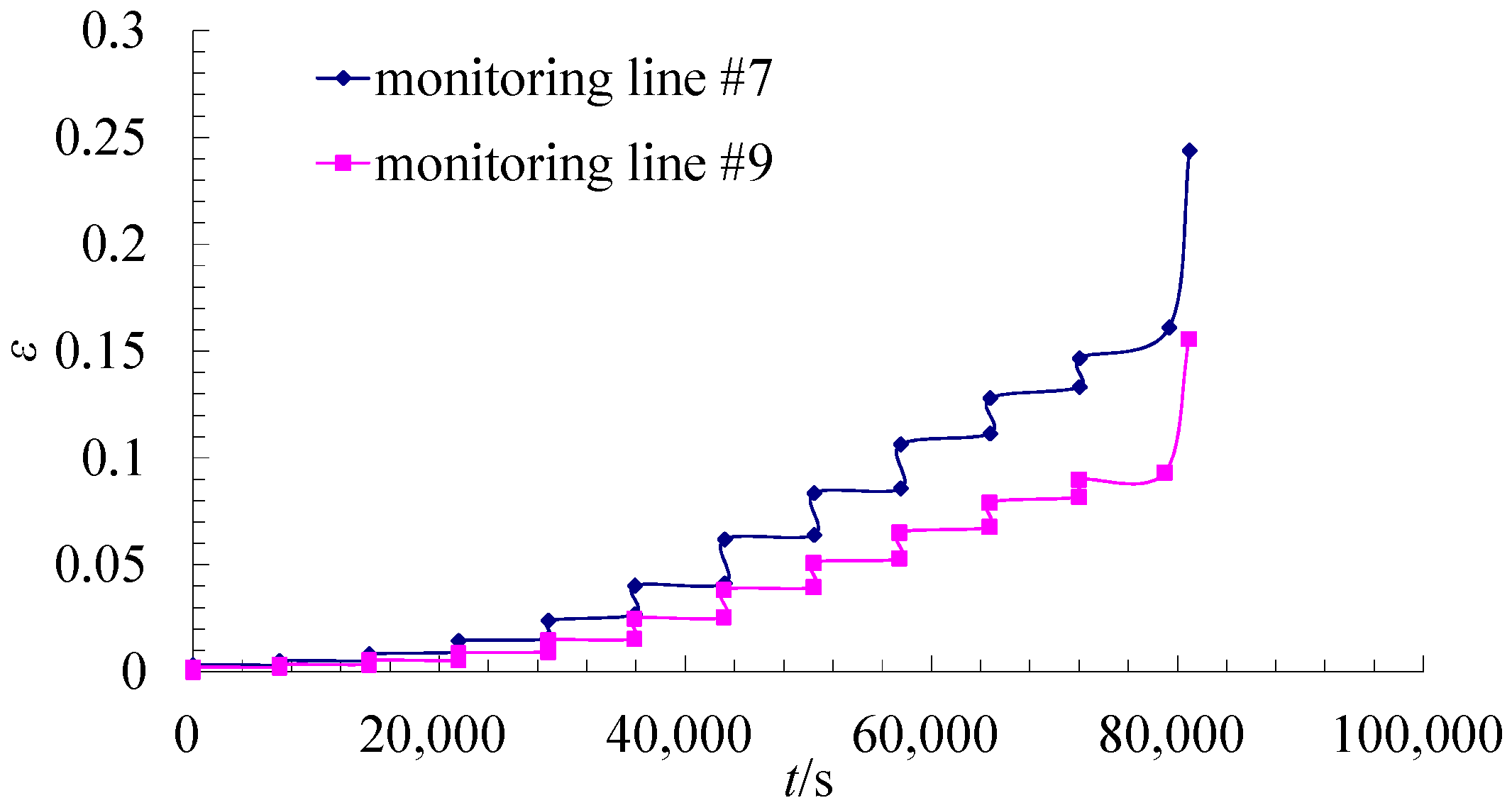
4.3. Creep Property and Scale Effect of SCMC

To analyse creep property and the scale effect of SCMC, the experimental results of large-size specimens and small-size specimens were compared.
(1) Creep Property
For the purpose of analysis, monitoring data were taken from the axial deformation monitoring lines #7 and #9, from which displacement-time curves of the two monitoring lines were derived, as shown in Figure 13.
Creep rupture of large-size specimens occurs when the axial deformation is 14 mm and axial strain is 0.154. When the loading time is shorter than 79,200 s (22 h) and the levelled load is less than 1.1 MPa, the average strain difference between each level is relatively small. After the levelled load exceeding 1.1 MPa, the average strain difference between each level begins to increase gradually and the specimens enter into an accelerated creep state. Meanwhile, as cracks develop, the specimens still have bearing capacity, and demonstrate strong plastic deformation features; cracks develop and propagate through the specimens in the axial direction.
(2) Scale effect
The experimental results show that the stress-strain change rules of specimens with different scales are basically the same, except for the compressive strengths and maximum deformations, which are slightly different. The compressive strength of large-size specimens is approximately 1.41 MPa, while the standard specimens have a compressive strength of approximately 1.48 MPa (a 4.96% increase); the maximum strain of the large-size specimens prior to rupture is about 0.15, for standard specimens it is about 0.16 (a 6.67% increase). The above data indicates that the scale effect of the tested SCMC is not significant.

5. Application of SCMC Mechanical Characteristics in Longwall Backfilling

According to the laboratory test results of the SCMC engineering mechanical characteristics, in the Taoyi Coal Mine of Handan Mining Group, backfilling using SCM is optimized. Through the monitoring data of surface subsidence and SCMC bearing stress, the stability of SCMC is verified.

5.1. Back Filling Rate and Backfilled Body Strength Design

Higher filling rates can improve overburden strata control performance during longwall retreat. However, excessive filling rates complicate and increase the costs of the operations. Consequently, the filling rate of the working face should be optimized based on the seam conditions and the control standards of the surface subsidence.
The designed filling rate of the working face (ηf) can be obtained using the mining height (M0), maximum permitted mining height (MZ), and roof sagging rate prior to filling (η0), and is given by [25]:
η f = ( 1 + η 0 ) M 0 M Z M 0
In the Equation (1), mining height (M0) and roof sagging rate prior to filling (η0) can be obtained by field measurement; maximum permitted mining height MZ = min(rimax/qcosα, r2Kmax/1.52qcosα, rεmax/1.52bqcosα), and q is the surface subsidence coefficient, α is the dip of the coal seam, b is the horizontal movement coefficient, r is the major influence radius, imax is the maximum permitted surface dip of the building, Kmax is the maximum permitted surface curvature, εmax is the maximum amount of surface horizontal deformation.
Different SCM backfilling technologies were implemented in Taoyi Coal Mine of Handan Mining Group. The average mining height of the coal seam at Taoyi Coal Mine is approximately 4 m; its cover depth, average seam dip, surface subsidence coefficient, horizontal movement coefficient, major influence radius, and roof sagging rate before filling are approximately 400 m, 10°, 0.78, 0.35, 200 m, and 4%, respectively. For the surface building protection level of II, the allowed amounts of surface deformations are: imax = 5.0, Kmax = 0.2, and εmax = 4.0. According to these indicators, the maximum permitted mining height of the coal seam in Taoyi Coal Mine is approximately 1.3 m and the filling rate in the working face should be not less than 72%. The details of SCM backfilling in Taoyi Coal Mine are shown in Table 1.
The main key layer that plays a critical role in controlling the subsidence of overlying strata will not break during the backfilling process. The strength of backfilled body should be sufficient to support the weight of the caved strata under the main key layer. The required backfilled body strength can be obtained using the average density and the thickness of layers under the main key layer, and is given by:
σ n = ρ a g H
In Equation (2), σn is the strength of backfilled body, ρa is the average density of overburden, H is the thickness of layers under the main key layer, g is the acceleration of gravity.
In the Taoyi Coal Mine, the maximum thickness of layers under the main key layer is 291.7 m (at No. 12706 backfilling face), and the average density of the overburden is 2500 kg·m−3. According to Equation (2), the required strength of backfilled body is 7.15 MPa.

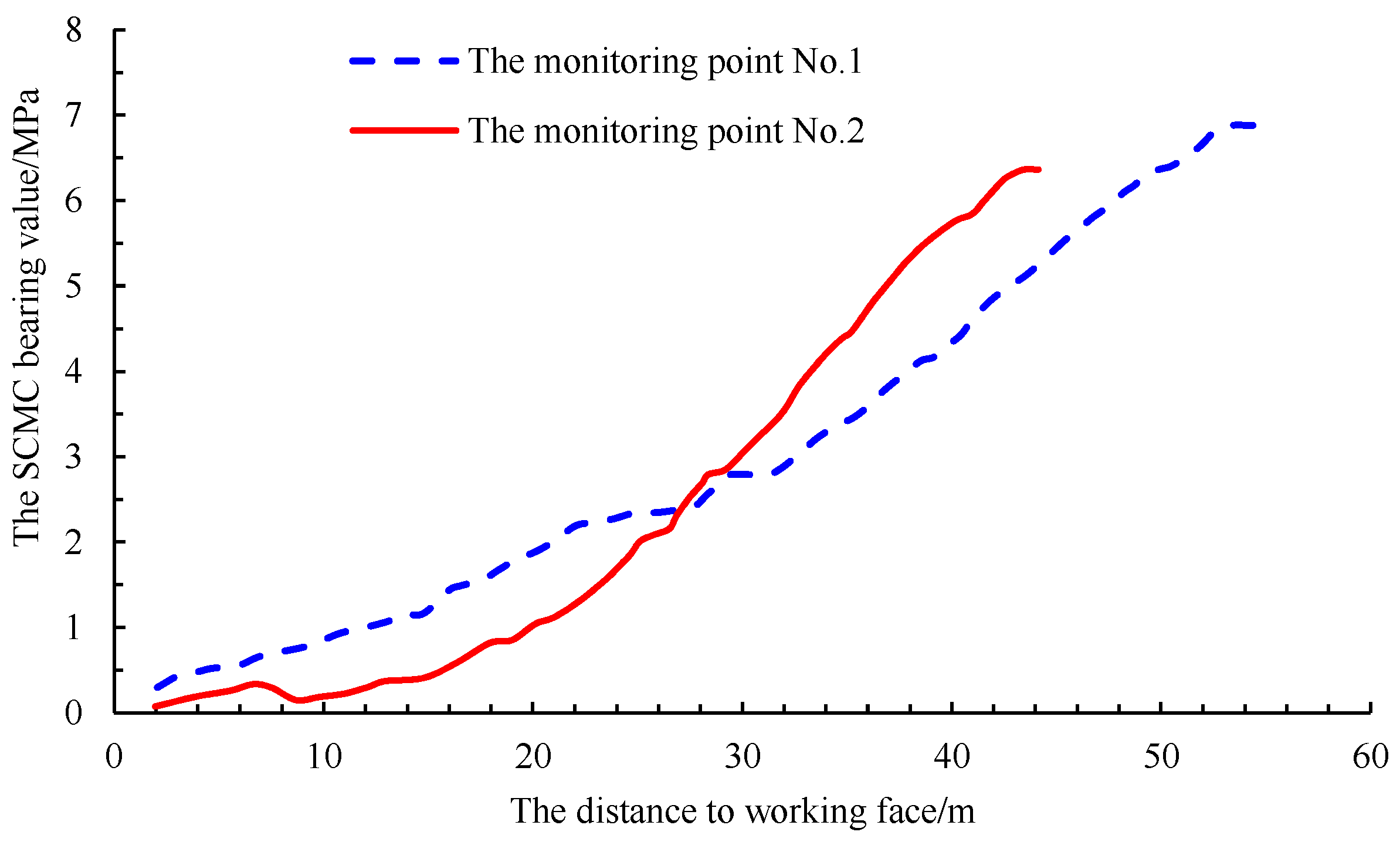
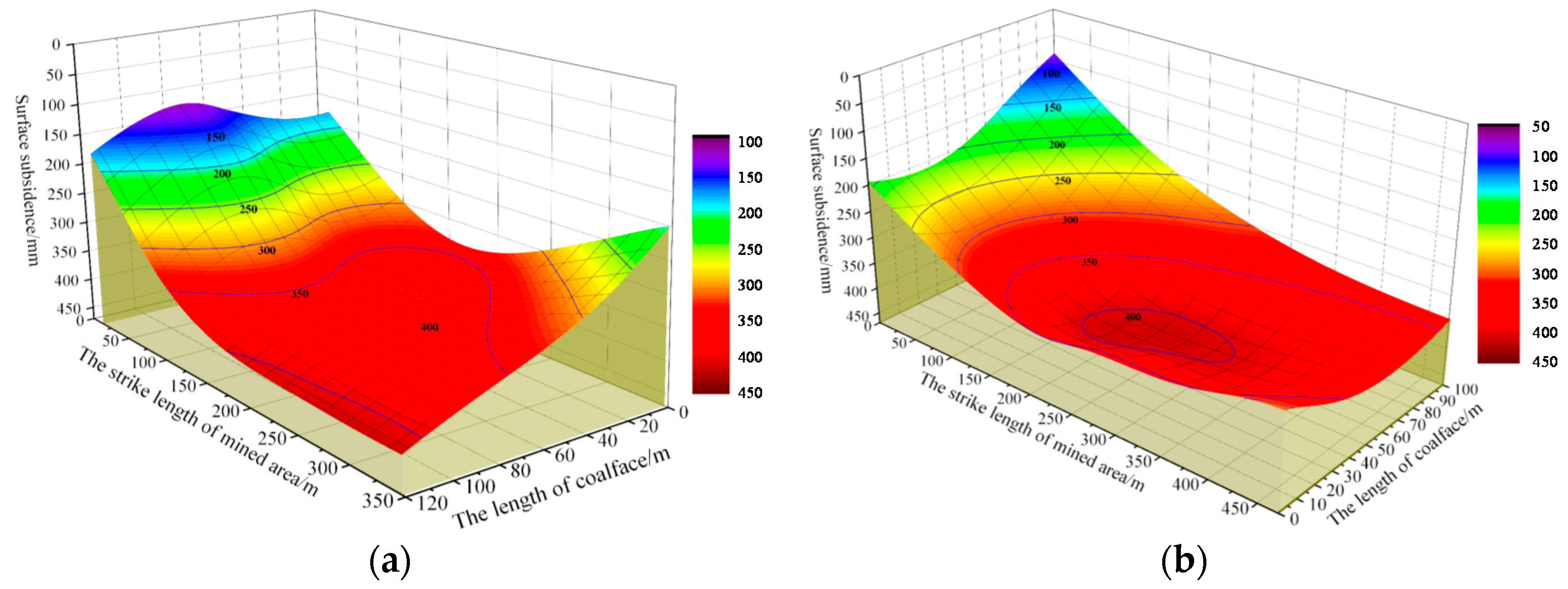
5.2. Impacts of SCMC Backfilling on Ground Control

(1) Surface Subsidence Characteristics in the Filling Region
Taking the surface subsidence situations of No. 6 backfilling face and No. 12706 backfilling face in the Taoyi Coal Mine as an example, the surface subsidence control effect after mining is explained. The surface subsidence situations after mining are shown in Figure 14 and the corresponding values are shown in Table 2.
Subsidence coefficients of No. 6 backfilling face and No. 12706 backfilling face are 0.101 and 0.103 respectively, which is less than the average surface subsidence coefficient (0.78) at Taoyi Coal Mine. The results indicate that the SCM backfilling technology has a good surface subsidence control effect.
(2) The Backfilled SCMC Bearing Stability
In order to monitor the backfilled SCMC bearing stress in the goaf, stress sensors were buried in the SCMC at rear of No. 12706 backfilling face. As shown in the Figure 15, the SCMC bearing stress has undergone a process of “Slowing-Increase-Stability” with working face retreated and is stable at 7 MPa finally; less than the measured critical deformation load (10 MPa).

6. Discussion

For test results that show that the strengths of SCMC specimens in different cementation states and under different compression conditions increase with curing time and decrease with water volume percentage, we think that both increasing curing time and decreasing water volume can benefit the coarsening of crystal by scanning. Hydration takes place during the preparation process of SCMC, and the SCMC contains meshy and acicular ettringite which are its main ingredients. When the water volume percentage is less than 95% or the curing duration is long, the ettringite needle-like structure is thicker, which can increase the strength of the SCMC.
The test results indicate that SCMC formed from a mixture of SCM and gangues is stronger than pure SCM alone. The strength of the caving roof is obviously higher than that of pure SCM, and plays a skeleton role in SCMC. At the same time, the shrinkage of SCM during solidification is reduced by gangues. Therefore, type IV specimens have the highest ultimate strength, and type-II and type-III specimens have similar ultimate strength. The ultimate strength of type I specimens is the lowest.
Specimens with different scales generally follow the same stress-strain change rules and the scale effect of the tested SCMC is not significant. First of all, SCM paste fluid should be fully stirred during the SCMC preparation process, ensuring the SCMC is denser and that there are fewer cracks. When SCMC specimens reach their ultimate strength, the deformation of the plastic is more pronounced. The SCMC specimens have high residual strength and a certain plasticity, so the size effect of SCMC is not obvious.

7. Conclusions

This paper studied the engineering mechanical properties of SCMC, which included strength changes and scale effects of SCMC in different cementation and stress states. The following major conclusions have been drawn:
(1)
The mechanical properties and scale effect of SCMC was studied in the experimental test. It was found that the compressive and tensile strengths of SCMC at different cementation states increase with curing time; the strengths of SCMC that was mixed with gangue are higher than that of pure SCMC. Under the conditions of partly and completely confined compression, the specimens show an increase of bearing strength and a decrease of deformation with curing time; and the specimens’ strength and critical deformation load are in inverse relation to the water volume percentage. Specimens with different scales generally follow the same stress-strain change rules, except in relation to compressive strengths and maximum deformation.
(2)
The engineering practice shows that, considering the engineering mechanical properties of cementation states and bearing characteristics of SCMC comprehensively, it can achieve better control effect of surface subsidence through optimizing the backfilling techniques parameters such as final strength and filling rate of backfilled body, according to specific geological and mining conditions.
The paper systematically investigated the characteristics of the SCMC for backfilling. The results advance the understanding and implementation of the backfilling technologies field, which further enhances subsidence control and other aspects of sustainable mining development.

Acknowledgments

We acknowledge the financial support for this work, provided by the National Natural Science Foundation of China (Grant No. 51474206, No. 51404254), the National Basic Research Program of China (973 Program-No. 2015CB162500), the Fundamental Research Funds for the Central Universities (2014QNA49).

Author Contributions

All authors contributed to this paper. Xufeng Wang prepared and edited the manuscript. Dongdong Qin and Bo Li participated in the data processing during the research process. Dongsheng Zhang revised and reviewed the manuscript. Chundong Sun and Chengguo Zhang partially participated in the literature research. Mengtang Xu was responsible for creating the figures.

Conflicts of Interest

The authors declare no conflict of interest.

Abbreviations

CPBcemented paste backfill
SCMCSuperhigh-water Content Material Concretion
SCMSuperhigh-water Content Material
BFBackfilling face

References

  1. Lv, W.Y.; Zhang, Z.H. Current situation and prospect of coal backfill mining. Technol. Adv. Mater. Res. 2012, 524, 421–425. [Google Scholar] [CrossRef]
  2. Zhang, J.X.; Zhang, Q.; Sun, Q.; Gao, R.; Germain, D.; Abro, S. Surface subsidence control theory and application to backfill coal mining technology. Environ. Earth Sci. 2015, 74, 1439–1448. [Google Scholar] [CrossRef]
  3. Johnson, G.; Kellet, W.H.; Mills, P.S. Aquapak: A cementitious pack material with high water content. In Proceedings of the International Strata Control Conference, Liège, Belgium, 20–24 September 1982. [Google Scholar]
  4. Buddery, P.S.; Hassani, F.P.; Singh, R.N. Study of Aquapak behaviour with reference to strata control requirements. Can. Geotech. J. 1984, 21, 621–633. [Google Scholar]
  5. Yao, Y.; Sun, H.H. A novel silica alumina-based backfill material composed of coal refuse and fly ash. J. Hazard. Mater. 2012, 213, 71–82. [Google Scholar] [CrossRef] [PubMed]
  6. Feng, G.M.; Ding, Y.; Zhu, H.J.; Bai, J.B. Experimental research on a superhigh-water packing material for mining and its micromorphology. J. China Univ. Min. Technol. 2010, 39, 813–819. [Google Scholar]
  7. Bharatkumar, B.H.; Narayanan, R.; Raghuprasad, B.K.; Ramachandramurthy, D.S. Mix proportioning of high performance concrete. Cem. Concr. Compos. 2001, 23, 71–80. [Google Scholar] [CrossRef]
  8. Thomas, E.G.; Nantel, J.H.; Notley, K.R. Fill Technology in Underground Metalliferous Mines; International Academic Services Ltd.: Kingston, ON, Canada, 1979. [Google Scholar]
  9. Cui, L.; Fall, M. An evolutive elasto-plastic model for cemented paste backfill. Comput. Geotech. 2016, 71, 19–29. [Google Scholar] [CrossRef]
  10. Fall, M.; Adrien, D.; Célestin, J.C.; Pokharel, M.; Touré, M. Saturated hydraulic conductivity of cemented paste backfill. Miner. Eng. 2009, 22, 1307–1317. [Google Scholar] [CrossRef]
  11. Yi, X.W.; Ma, G.W.; Fourie, A. Compressive behaviour of fibre-reinforced cemented paste backfill. Geotext. Geomembr. 2015, 43, 207–215. [Google Scholar] [CrossRef]
  12. Klein, K.; Simon, D. Effect of specimen composition on the strength development in cemented paste backfill. Can. Geotech. J. 2006, 43, 310–324. [Google Scholar] [CrossRef]
  13. Hughes, P.B.; Pakalnis, R.; Deen, J.; Ferster, M. Cemented paste backfill at Stillwater Mine. In Proceedings of the 47th US Rock Mechanics/Geomechanics Symposium 2013, San Francisco, CA, USA, 23–26 June 2013; Volume 2, pp. 1230–1236. [Google Scholar]
  14. Klein, K.; Simon, D. Electromagnetic properties of cemented paste backfill. J. Environ. Eng. Geophys. 2006, 11, 27–41. [Google Scholar] [CrossRef]
  15. Simon, D.; Grabinsky, M. Apparent yield stress measurement in cemented paste backfill. Int. J. Min. Reclam. Environ. 2013, 27, 231–256. [Google Scholar] [CrossRef]
  16. Yilmaz, E.; Belem, T.; Bussière, B.; Mbonimpa, M.; Benzaazoua, M. Curing time effect on consolidation behaviour of cemented paste backfill containing different cement types and contents. Constr. Build. Mater. 2015, 75, 99–111. [Google Scholar] [CrossRef]
  17. Nasir, O.; Fall, M. Coupling binder hydration, temperature and compressive strength development of underground cemented paste backfill at early ages. Tunn. Undergr. Space Technol. 2010, 25, 9–20. [Google Scholar] [CrossRef]
  18. Huang, S.; Xia, K.W.; Qiao, L. Dynamic tests of cemented paste backfill: Effects of strain rate, curing time, and cement content on compressive strength. J. Mater. Sci. 2011, 46, 5165–5170. [Google Scholar] [CrossRef]
  19. Fall, M.; Beleni, T.; Sanib, S.; Benzaazoua, M. Experimental characterization of the stress-strain behaviour of cemented paste backfill in compression. J. Mater. Sci. 2007, 42, 3914–3922. [Google Scholar] [CrossRef]
  20. Ghirian, A.; Fall, M. Coupled behaviour of cemented paste backfill at early ages. Geotech. Geol. Eng. 2015, 33, 1141–1166. [Google Scholar] [CrossRef]
  21. Celestin, J.C.H.; Fall, M. Thermal conductivity of cemented paste backfill material and factors affecting it. Int. J. Min. Reclam. Environ. 2009, 23, 274–290. [Google Scholar] [CrossRef]
  22. Ouellet, S.; Bussiere, B.; Aubertin, M.; Benzaazoua, M. Characterization of cemented paste backfill pore structure using SEM and IA analysis. Bull. Eng. Geol. Environ. 2008, 67, 139–152. [Google Scholar] [CrossRef]
  23. Ercikdi, B.; Yilmaz, T.; Kulekci, G. Strength and ultrasonic properties of cemented paste backfill. Ultrasonics 2014, 54, 195–204. [Google Scholar] [CrossRef] [PubMed]
  24. Yilmaz, T.; Ercikdi, B.; Karaman, K.; Kulekci, G. Assessment of strength properties of cemented paste backfill by ultrasonic pulse velocity test. Ultrasonics 2014, 54, 1386–1394. [Google Scholar] [CrossRef] [PubMed]
  25. Wang, X.F.; Zhang, D.S.; Sun, C.D.; Wang, Y. Surface subsidence control during bag filling mining of super high-water content material in the Handan mining area. Int. J. Oil Gas Coal Technol. 2016, 13, 87–102. [Google Scholar] [CrossRef]
Figure 1. The scanning electron microscope (SEM) photos of the superhigh-water content material concretion (SCMC) micro-characteristics with different water volume percentage. (a) Water volume percentage of 95%; (b) water volume percentage of 97%.
Energies 10 01592 g001
Figure 2. Schematic Diagram of an Open-type Backfilling of SCM. 1—main roof; 2—immediate roof; 3—backfilled body; 4—hydraulic support; 5—coal body; α-coal bed pitch.
Energies 10 01592 g002
Figure 3. Classification of the backfilled SCMC. 1—main roof; 2—immediate roof; 3—hydraulic support; 4—coal body.
Energies 10 01592 g003
Figure 4. Compression State of the backfilled SCMC. 1—main roof; 2—immediate roof; 3—floor; 4—hydraulic support; 5—coal body; 6—SCMC within 24 h; 7—SCMC after 24 h; L-width of pocket.
Energies 10 01592 g004
Figure 5. System component schematics.
Energies 10 01592 g005
Figure 6. Confined compression test. (a) Partly confined compression test; (b) Completely confined compression test.
Energies 10 01592 g006
Figure 7. Loading and destruction process of large-size specimen. (a) Specimen without damage; (b) Totally destroyed.
Energies 10 01592 g007
Figure 8. Stress-strain curves of the four types of specimens after a curing time of 24 h.
Energies 10 01592 g008
Figure 9. Strength change characteristics of specimens at curing time. (a) Compressive strength; (b) Tensile strength.
Energies 10 01592 g009
Figure 10. Stress-strain curves of specimens subjected to partly confined compression.
Energies 10 01592 g010
Figure 11. Deformation behaviour of specimens under different loads at different ages.
Energies 10 01592 g011
Figure 12. Critical deformation load characteristics of the specimens.
Energies 10 01592 g012
Figure 13. Displacement–time curves of monitoring lines #7 and #9.
Energies 10 01592 g013
Figure 14. The surface subsidence situations after mining. (a) No. 6 backfilling face; (b) No. 12706 backfilling face.
Energies 10 01592 g014
Figure 15. The bearing stress of SCMC in the goaf.
Energies 10 01592 g015
Table 1. The details of SCM backfilling in the Taoyi Coal Mine.
Working FaceNo. 1 BFNo. 2 BFNo. 3 BFNo. 4 BFNo. 5 BFNo. 6 BFNo. 12702 BFNo. 12706 BF
Backfill technologyopen-typepocket-typeopen-typepocket-typeopen & pocket-typeopen-typepocket-typepocket-type
Filling rate/(%)8283.792.18298.7858982
BF: Backfilling face.
Table 2. The value of surface subsidence situations in the filling region.
Working FaceMaximum Surface Subsidence Values/mmFilling Rate/(%)Subsidence Coefficients
No. 6 backfilling face405850.101
No. 12706 backfilling face415820.103

