Introduction
Eye Gaze Tracking (EGT) system includes a device able to continuously acquire and follow eye position over time and compute gaze point coordinates in the environment around the subject through an analytical relationship. In the current literature, EGTs have been exploited in different fields, ranging from the medical field (detecting the relationship between oculomotor characteristics and cognition and/or mental states) to user interaction (helping people with disabilities or level attention detection), from multimedia to product design (C. Morimoto & Mimica, 2005). Currently, most EGTs are based on the Video-OculoGraphy (VOG) technique, which is a method for tracking eye movements through computer vision techniques used to process eye images (Van der Geest & Frens, 2002). Through VOG, pupil position and iris landmarks are detected by means of image processing algorithms and used to calculate both eye rotation angles and the eye center. VOG-based EGTs can be classified into two main categories identified by the position of the camera, that is dedicated to acquiring eye images with respect to the user. In particular, if the camera is placed on a fixed support in front of the subject the systems are named remote EGTs, when placed on the head of the subject they are named Head—Mounted EGTs (HMEGTs), i.e., portable EGTs. Of course, the choice between the two types of systems poses different technical and methodological challenges. Generally, in laboratory environment remote EGTs are employed. They allow a quite precise measure, but impose limitations in the kind of information that can be retrieved. Specifically, remote EGTs could make use of either the chin support to block the user’s head resulting unsuitable for long term acquisitions but with a good accuracy, or intelligent algorithms such as Active Shape Model (ASM) (T. F. Cootes, Taylor, Cooper, & Graham, 1995) to detect the user’s eye allowing for limited head movements. They often require really expensive high definition camera that make remote EGTs suitable for investigating oculomotor strategy in neurological investigation, (Meyer, Böhme, Martinetz, & Barth, 2006). On the contrary, HMEGTs have opened new scenarios for research and for markets where the user is free to move his head on which the equipment is directly mounted (Zhu & Ji, 2007). HMEGTs make it possible to investigate the eye-movement during natural tasks in uncontrolled environments (M. Land & Lee, 1994) and in real life scenarios. Although in the real life scenario some uncontrollable external factors such as illumination changes could make the experimental setting time-consuming and not easily repeatable, at the same time HMEGTs allow for dynamical monitoring even in case of time-variant experimental paradigms (Hayhoe & Ballard, 2005). One of the most significant approach to prevent luminosity change issues is based on infrared (IR) illumination. In particular, spectral (reflective) properties of the pupil, under near-IR illumination, are exploited to maximize the image-contrast (C. Morimoto, Amir, & Flickner, 2002; C. Morimoto & Mimica, 2005). Nevertheless, in order to combine the advantage of supervised laboratory settings with real-life-like environments one of the most interesting approach is based on virtual reality immersive space (Fahrenberg, Myrtek, Pawlik, & Perrez, 2007). Virtual Reality (VR) offers an excellent compromise between laboratory and natural world accounting for a systematic control of the stimuli and the variables involved. Given the advantages of immersive VR spaces, HMEGTs have opened up new exploiting directions of the human interaction over time (Henderson, 2003; Jacob & Karn, 2003) focussing on understanding and coding naturalistic behaviour (Hayhoe & Ballard, 2005). However, even though many researches exploited HMEGTs for studying user attention, their perception of surrounding objects, and user interest as well as eye pattern in affective stimulation obtaining good results, (Lanatà, Valenza, & Scilingo, 2013; de Lemos, Sadeghnia, Ólafsdóttir, & Jensen, 2008; Partala & Surakka, 2003; Lanata, Armato, Valenza, & Scilingo, 2011), the performances of these systems drastically decade when the user head is free to move for example in the investigation of VR space navigation (C. Morimoto & Mimica, 2005). In this context, this work aims at developing a new HMEGT (named HAT-Move) to be used either in real life or in completely immersive 3D-virtual reality worlds.
Head Movement Issue
The possibility of freely moving the head with HMEGTs requires a robust and reliable identification and tracking of the pupil center and gaze point. Generally, all of the eye tracking systems developed both for market and research purpose make use of an uneasyto-perform calibration procedure, that should be very accurate. As a matter of fact, the better is the calibration the better is the outcome of the EGT. In particular, given a certain number of points (i.e, calibration points) in the real world and fixed their coordinates on the acquired image, the calibration is an analytical relationship that maps the coordinates of the eye gaze computed by the system into the coordinates of the calibration points (Hartley & Zisserman, 2000).. This procedure can be differentiated by both the number of calibration points and the kind of mathematical models used to generate this relationship, (Ramanauskas, Daunys, & Dervinis, 2008). In the literature many efforts have been spent to improve gaze estimation in terms of increasing tolerance to head movements, and as a consequence to improve and simplify the calibration process (Cerrolaza, Villanueva, & Cabeza, 2008; Johnson, Liu, Thomas, & Spencer, 2007; Evans, Jacobs, Tarduno, & Pelz, 2012). In fact, in spite of several attempts of EGTs to enable head movements which can be found in the literature, the head movement keeps remaining an open issue. Babcock et al. introduced a projected grid of 9-points in front of the person, (Babcock, Pelz, & Peak, 2003), as a reference for calibrating the eye position with the camera scene image. Even though this system is designed to be used in natural task it requires many calibration steps during the experiments. Moreover, since a measure of the movement of the head is missing the recalibration process is based on human-operator expertise. Rothkopf et al. tried to use head movements to disambiguate the different types of eye movements when subjects move head and body (Rothkopf & Pelz, 2004). However, the performance of the algorithm declines for large motions in roll, and sometimes the algorithm fails completely. Data analysis showed that the recordings suffered from a significant noise level compared to experimental conditions in which the subject does not move neither the body nor the head, highlighting that much more complex patterns of eye and head movements had to be considered. Johnson et al. allowed relatively unrestricted head and/or body movements (Johnson et al., 2007) tracking them by a visual motion tracker but large errors were found. Moreover two relevant drawbacks have been reported: the eye tracker became less reliable at larger eye rotations and errors arose if there was a shift in the relative position 3D reference on the eye-tracker’s visor and the participant’s head. As a result of this background it is worthwhile noting that augmenting the eye trackers capacity of differentiating among the movements of the head and the eyes could improve their ability in performing an effective and robust gaze detection. In this view, HAT-Move aims at overcoming the state of the art proposing a novel method for integrating head movement contribution in a free to move eye gaze detection.
Eye Movement
One of the crucial point of the proposed system is the ability in detecting and monitoring the eye movement. Specifically, eye movements can be classified as pursuit and smooth pursuit, saccades and nystagmus movement. Pursuit movements or smooth pursuit are eye movements used for tracking an object in movement, therefore a moving image has to remain constrained to the fovea to achieve a stable image seen by the user. Fovea is a small area of the retina with a very high visual acuity, and it covers about 2 degrees of visual angle. Saccades are rapid movements of eyes for scanning a visual scene. They are also present when the subject is fixating one point (Findlay, 2009). Nystagmus indicates involuntary eye movements. More specifically, when the head rotates about any axis, distant visual images are sustained by rotating eyes in the opposite direction on the respective axis. Physiologically, nystagmus is a form of involuntary eye movement that is part of the vestibulo-ocular reflex (VOR), characterized by alternating smooth pursuit in one direction and saccadic movement in the other direction (Westheimer & McKee, 1975). As a matter of fact the brain must turn the eyes so that the image of the fixed object falls on the fovea. Of note, the pursuit system keeps up the moving object in order to allow the brain to move the eyes in opposite direction to head motion, otherwise, image slip on the retina and a blurred image is produced.
In this work, we propose an innovative version of the already partially proposed wearable and wireless eye tracking system (Armato, Lanatà, & Scilingo, 2013). The new system, HAT-Move, is comprised of only one light camera able to capture simultaneously the scene and both eyes of the subject through a mirror. The system calculates the gaze point in real-time both indoor and outdoor. Moreover, a precise and fast Inertial Motion Unit (IMU) was added to render it independent from involuntary head movements, during the calibration phase, or to render it robust to head movements needed to focus on objects out of the visual space. Specifically, in this study we evaluated the contribution, in terms of angular error, of the head movement integration with respect to standard eye tracking. Moreover, HAT-Move system inherits from the previous version the robustness against illumination variation implementing a normalization of the illumination through a Discrete Cosine Transform (DCT) of the acquired images. Further details are reported in Section.
Materials and Methods
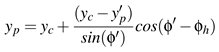
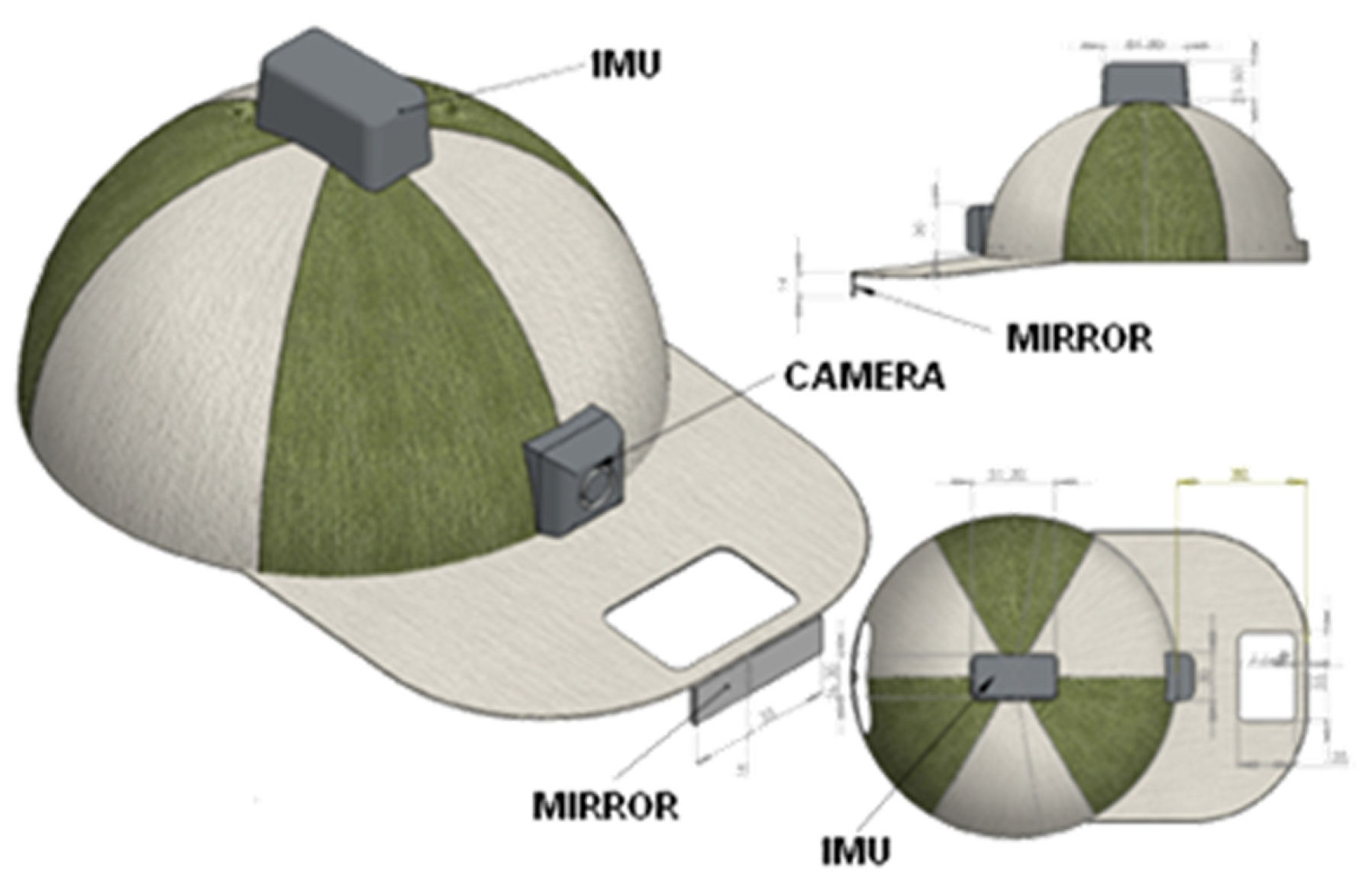
The HAT-Move eye tracking system was developed in two configurations: the “baseball” hat (see
Figure 1) and the head band (see
Figure 2). They are technically and functionally equivalent, although the former can be considered aesthetically more pleasant. It is comprised of a wireless camera that is light and small, with an Audio/Video (A/V) transmitter of up to 30
m of distance. The camera has a resolution of 628 × 586 pixels with
F2.0,
D45° optic, and 25 frames per second (f.p.s.). In addition, the InfraRed (IR) filter, which is actually present in each camera, was removed and a wide-angle-lens was added allowing to enlarge the view angle and acquire natural infrared components increasing both the image resolution and the contrast between pupil and iris. This system is able to simultaneously record the visual scene in front of the subject and eye position. This is achieved through a mirror(5 x 0.6 cm) placed in front of the user’s head (see
Figure 2). The system is completely customizable on the user’s forehead (see
Figure 2). In addition, a wireless Inertial Motion Unit is placed atop the head close to the azimuth rotation center (see
Figure 3). The IMU allows for the acquisition of head movements and rotations during natural activities, allowing for the correction of eye gaze estimation taking into account both the movements during the calibration phase and the “Vestibulo-Ocular Reflex” (VOR) contributions. The adopted IMU provides the three rotation Euler-angles of the head (see
Figure 3) with a sampling frequency of 100 Hz. The system is intended to be wearable, minimally invasive, capable of eye tracking, estimating pupil size, lightweight, and equipped for wireless communication. Moreover the system is designed to be attractive and aesthetic (in a baseball-like version), and able to process the eyegaze pattern in real-time. The HAT-Move system uses a passive approach for capturing ambient light reflected by the eye (VOG). The customized image acquisition system is able to acquire both natural light along with its IR components that are already present in the natural light bandwidth. Therefore, the system presents IR lightning advantages increasing the pupil-iris contrast and avoiding any possible eye injury due to artificial IR illuminators. The block diagram in
Figure 4 shows the methodology used to process the acquired image, in which both eyes and scene are presented. The whole processing chain is comprised of a series of algorithms for the detection of the eye center and for the integration of the head rotation angles and the correction of involuntary head movements. Specifically, the eye center detection is achieved through the following steps: eye region extraction algorithm, photometric normalization algorithm of illumination, extraction of the pupil contour, and ellipse fitting algorithm as well. Afterwards, the center of the eye is detected, Eulero-head-angles together with the pupil center are integrated into the mapping function to map the eye center and movements into the image plane. The processing chain is fully described in the following sections.
Illumination normalization
Illumination normalization relies on an algorithmic strategy to keep stable illumination conditions throughout the captured images. More specifically, environmental illumination changes are reflected in the acquired images as a variation of the eye representation in terms of intensity thereby strongly reducing the contrast between eyes and landmark. The standard approach is based on the Retinex theory, (E. H. Land & McCann, 1971) whereby the effect of a non-uniform illumination is eliminated and is completely independent of any a-priori knowledge of the surface reflectance and light source composition. According to this theory, the image intensity
I(
x,
y) can be simplified and formulated as follows:
where
R(
x,
y) is the reflectance and
L(
x,
y) is the illuminance at each point (
x,
y). The luminance
L is assumed to contain low frequency components of the image while the reflectance
R mainly includes the high frequency components of the image. The technique used here is the result of a our previous work, in which seven different photonormalization techniques were tested and compared, i.e., Single Scale Retinex (SSR), Multi Scale Retinex (MSR), Single scale selfQuotient Image (SQI), Multi Scale selfQuotient image (MSQ), Discrete Cosine Transform(DCT), WAveletbased Normalization algorithm (WAN), and Normalization Histogram (NH). In that paper our key approach was to evaluate, in terms of accuracy of eye tracking, pupillometry and execution time under three different brightness conditions: Laboratory, Sunlight, and Darkness. Results showed that the DCT method was the most effective in terms of accuracy of gaze point and pupillometry. More details can be found in (Armato et al., 2013). The DCT technique compensates for illumination variations by truncating the low frequency components of the discrete cosine transform (DCT) in the logarithmic domain. In the logarithmic domain the theory is formulated as follows:
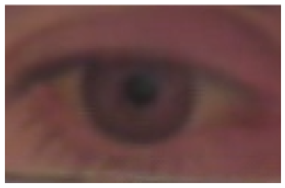
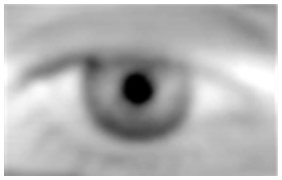
Figure 7 shows the output of the DCT algorithm applied to gray scale image reported in
Figure 6.
Pupil tracking and ellipse fitting
This section deals with the method used to extract the pupil contours. The method is comprised of several blocks in which the acquired eye image is first binarized in order to separate the pupil from the background by using a threshold in the image histogram; then a geometrical method was used to reconstruct pupil contours and to remove outliers belonging to the background, details of this algorithm con be found in (Armato et al., 2013). Following the geometrical detection of the points belonging to the pupil, an ellipse fitting algorithm is implemented for pupil contour reconstruction and for detecting the center of the eye. In the literature, the ellipse is considered to be the best geometrical figure representing the eye, being the eye image captured by the camera a projection of the eye in the mirror. Over the last decade many ellipse fitting algorithms have been proposed (Forsyth & Ponce, 2002; Bennett, Burridge, & Saito, 2002), although most work offline. In our system we used the Least Square (LS) technique, which is based on finding a set of parameters that minimizes the distance between the data points and the ellipse, (Fitzgibbon, Pilu, & Fisher, 2002). According to the literature this technique fulfills the real time requirement (Duchowski, 2007). Specifically, we follow the algorithm proposed by Fitzgibbon et al., which is a direct computational method (i.e., B2AC, it is the exact name of Fitzgibbon’s algorithm which is based on the solution of a quadratic polynomial) based on the algebraic distance with a quadratic constraint, in which a gaussian noise is added for algorithm stabilization, (Maini, 2005). Afterwards, the center of the eye is computed as the center of the fitted ellipse. A detailed description of the methods can be found in (Armato et al., 2013).
Figure 8 shows the result of pupil tracking and the ellipse fitting algorithm for reconstructing pupil contours.
Mapping of the position of the eye
The mapping procedure aims at associating the instantaneous position of the center of the eye to a point of the scene. This point is named
gazepoint. This procedure is mainly based on a mathematical function, named
mapping f unction, which is an equation system constituted of two second order polynomial functions (C. H. Morimoto, Koons, Amir, & Flickner, 2000) defined as:
where
xsi,
ysi are the coordinates of a point on the image plane (i.e., the coordinates of the point on the screen mapped into the image plane captured by the camera), and
xei,
yei are the coordinates of the center of the eye coming from the ellipse fitting block, referred to the image plane as well. The procedure is intended to solve the equation system by means of a calibration process. Once the system is positioned onto the subject’s head in a manner that eyes and scene are simultaneously presented in the image captured by the camera, the user is asked to look at some specific points on the screen (calibration process). These points are identified by coordinates
si = (
xsi,
ysi) referred to the image plane (i.e., the image captured by the camera), (see
Figure 5). Since the coordinates of the calibration points are known to solve the equation system, we have to compute the coefficients
a1,1—to—6, and
a2,1—to—6 that are unknowns. The results are achieved because each calibration point defines 2 equations, and, considering a 9-point calibration process, the system is over constrained with 12 unknowns and 18 equations and can be solved using Least Square Method (LSM). Head movements mainly affect the calibration process, resulting in artifact movement that degrades eye estimation and consequentially the point of gaze as well. Two different problems related to these movements arise. The first consists of the modification of the image plane position, which follows the head rotations being attached to the forehead, while the second is due to the involuntary movement. In this work an innovative integration process is implemented, as described in the next paragraph.
Movement Integration Process
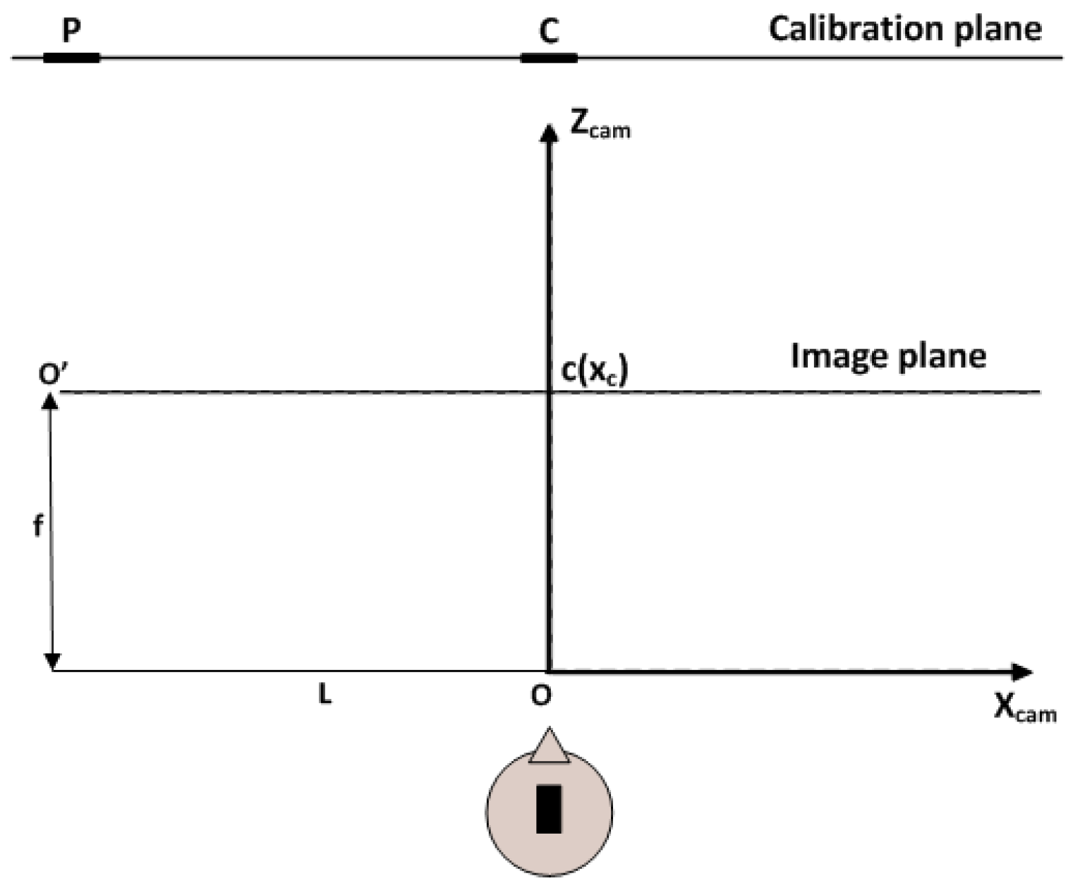
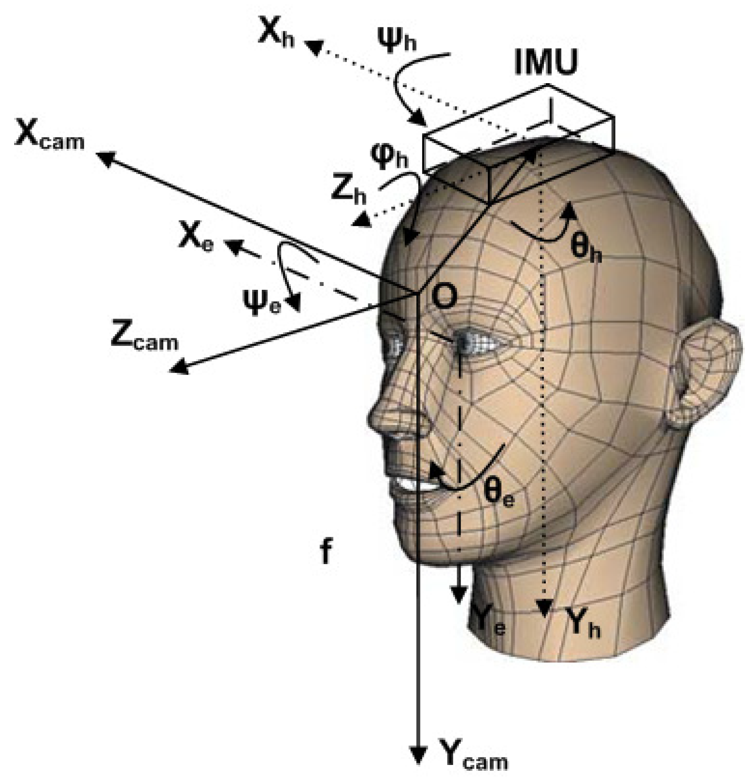
This integration process is related to the adjustment of the eye gaze as a consequence of changes in the calibration plane orientation with respect to the camera and the compensating eye rotations against head rotations. These issues are mainly due to the user’s inability to hold the head still for the whole duration of the calibration process. Consequently, these movements reduce the system accuracy. This process is based on data gathered from the IMU. First of all, according to
Figure 10,
OhXhYhZh, we define the cartesian system in the reference frame of the IMU;
OXcamYcamZcam the cartesian system in the reference frame of the camera;
OXeYe a cartesian system in the reference frame of the center of the eye;
O′xiyi the cartesian system on the image plane;
f the focal distance;
c(
xc,
yc) the projection of the central point of the calibration plane onto the image plane;
si(
xsi,
ysi) the projection of
P(
x,
y,
z), which is a generic calibration point, onto the image plane. Moreover, we also define the following rotations: θ
h, ψ
h and ϕ
h head rotation angles around
Yh,
Xh, and
Zh axes, respectively; and θ
e and ψ
e the eye rotation angles around
Ye and
Xe, respectively. The Movement Integration (MI) is performed during the acquisition of the 9 target points
si = (
xsi,
ysi), the 9 points related to eye positions
ei = (
xei,
yei), and synchronously the Euler angles of the head (θ
h, ϕ
h and ψ
h see
Figure 10). In particular, the MI process performs both the realignment of eye center position on the image plane when the VOR occurs and the remapping of the calibrated space onto the image plane when the head of the user is rotating. Hence at the end of the process, the mapping function will compute the adjusted coordinates of the eye center
xei,
yei, and the corrected coordinates of the calibration point,
si = (
xsi,
ysi), both referred to the image plane. Referring to the eye rotation angles, they were estimated taking advantage of VOR contributions by means of Vestibulo-Ocular calibration curves. These curves are estimated to quantify eye rotations by a mathematical model for transforming eye rotations, expressed in degrees, into movements of the eye center along the vertical and horizontal axes, expressed in pixels (Crawford & Vilis, 1991). Here, vestibulo-ocular curves are two curves (one is for the rotation ψ around
x axis and the other is for the rotation θ around
y axis) computed asking the user to rotate the head around the horizontal and vertical axes fixing the gaze on point “C” in front of him while acquiring eye tracking, gaze, head movements and the scene over time. A linear fitting is applied to both rotations for extracting gain and offset, as expressed by the formula:
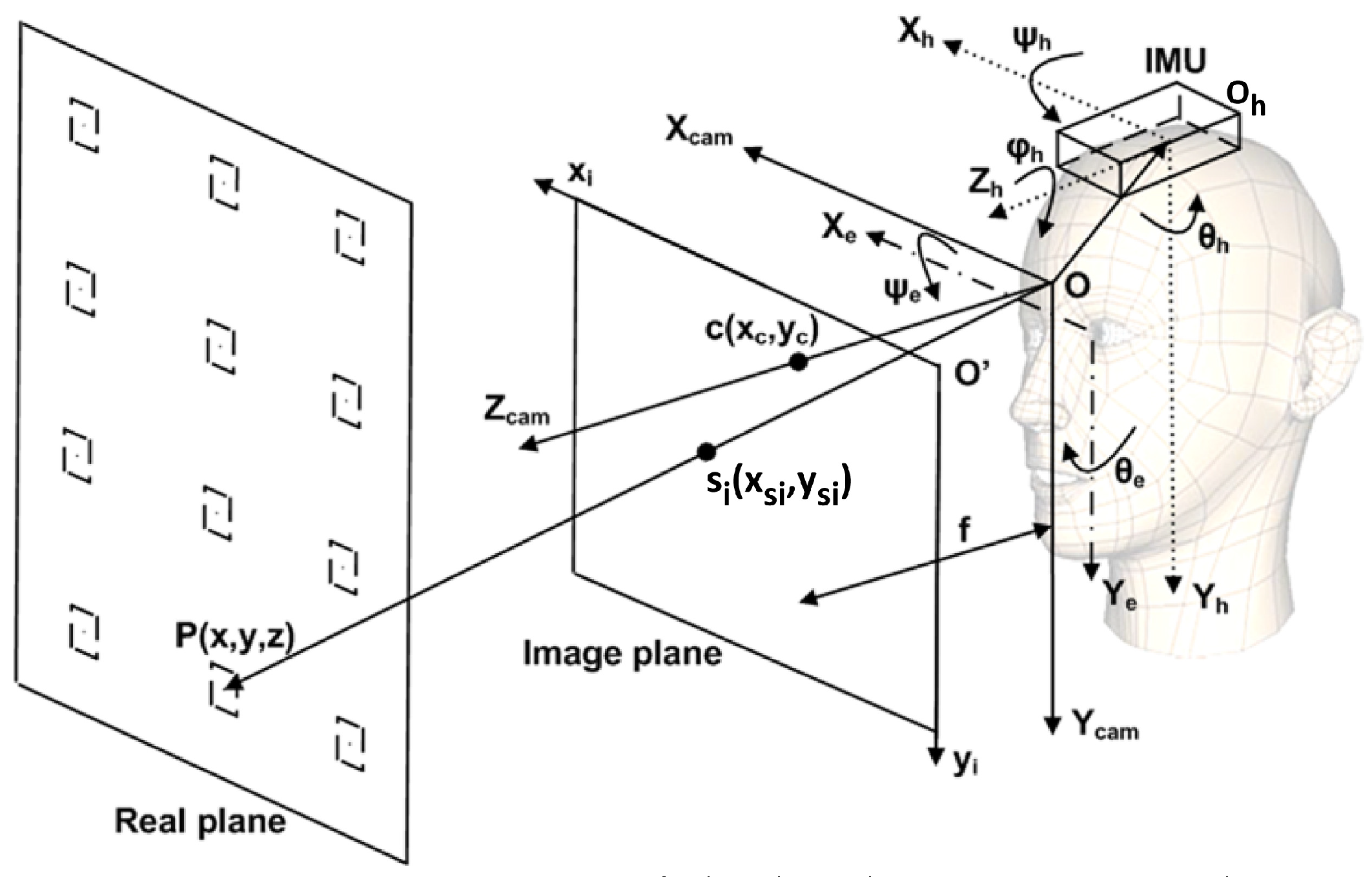
Figure 10.
Representation of the head, IMU, image plane and real plane, respectively. In the figure, Xe, Ye are the axes in the reference frame of the eye; Xcam, Ycam, Zcam are the axes in the reference frame of the camera; xi,yi are the axes in the reference frame of the image plane; Xh, Yh, Zh are the axes in the reference frame of the center of the head where the IMU is placed; ψh, θh, ϕh are the Euler-angles of the head rotation while ψe, θe, are the Euler-angles of the eye rotation; c(xc, yc) is the projection of the central point of the calibration plane on the image plane; si(xsi, ysi) the projection of P(x, y, z), which is a generic calibration point, on the image plane.
Specifically, the adjusted eye rotations are computed according to the following equations (the symbol ≜ indicates that it is a new formulated equation):
![Jemr 08 00019 p001]()
![Jemr 08 00019 p002]()
![Jemr 08 00019 p003]()
Figure 11.
Initial condition of the calibration.
Figure 11.
Initial condition of the calibration.
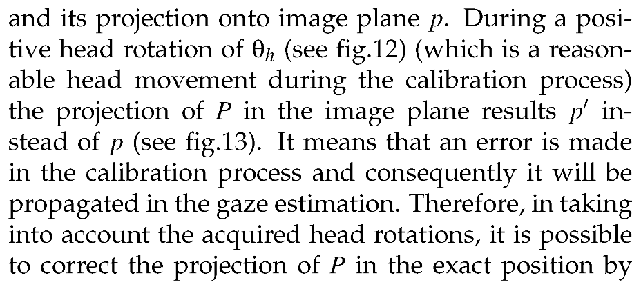
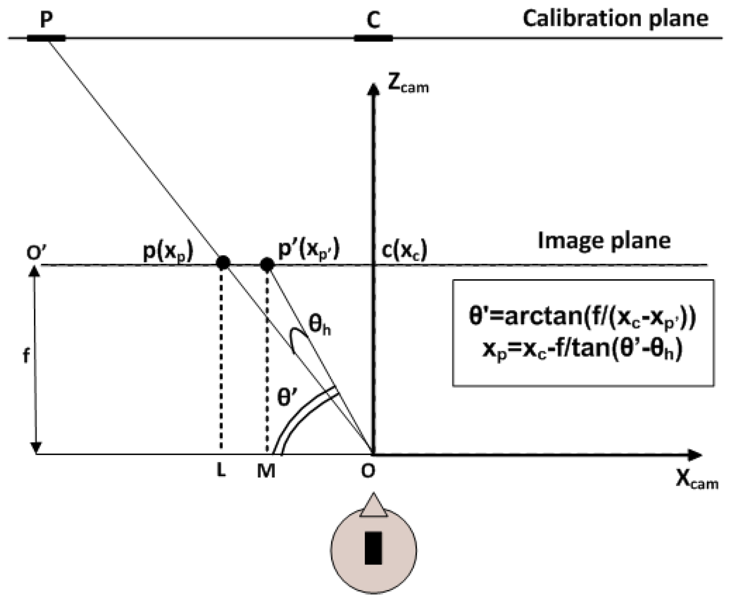
Figure 12.
Representation of the positive θh rotation.
Figure 12.
Representation of the positive θh rotation.
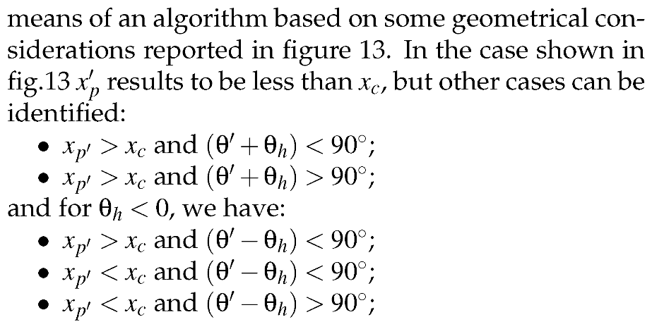
Figure 13.
Representation of the error after positive θh rotation.
Figure 13.
Representation of the error after positive θh rotation.
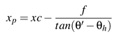
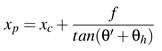
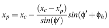
Considering all of the cases mentioned above, the correction along the
x axis can be reassumed by the following equations:
if
<
xc then
otherwise
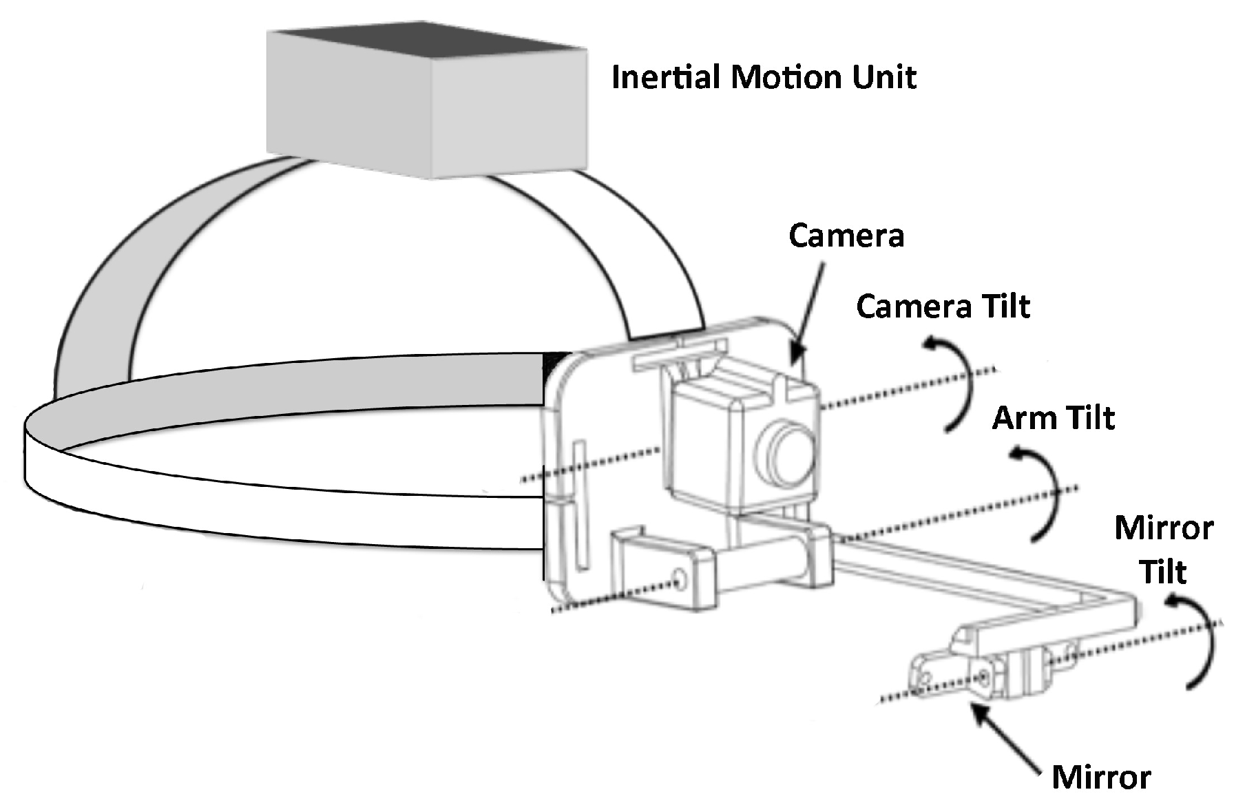
The
yp corrections are the same as
xp corrections using the angle ψ
h instead of θ
h; however, the relationships are inverted with respect to the sign of the angle. Therefore:
if
<
yc then
otherwise
The correction by ϕ
h gives a contribution for both
x and
y coordinates. All cases for both ϕ
h < 0 and ϕ
h > 0 can be summarized by the following equations:
if (
<
xc and
<
) or (
>
xc and
>
) then
otherwise
The correct coordinates of both the eye center and the calibration points will be used in the mapping function system (eq. 3, 4) to detect the new gaze point.
Experimental setup
This section deals with two experimental setups. The first aims at defining a protocol to validate the accuracy of the HAT-Move and the relevance of correction process (hereinafter named Accuracy Estimation) in laboratory settings, while the second is mainly a proof of concept concerning the use of the HAT-Move system in a 3D VR scenario (hereinafter named VR Estimation). To this extent we evaluated the applicability of the HAT-Move with the correction process in a quasi naturalistic environment when the subject is free to move his head and to walk around in the VR space.
Accuracy Estimation. The first experiment was performed by group of 11 subjects who did not present any ocular pathologies. All of the subjects were asked to sit on a comfortable chair placed in front of a wall (3 × 3 m
2) at a distance of 2 m, while wearing the system. The wall surface was constituted of a set of black squares (2 cm per side) immersed into a white background. This controlled environment permitted to verify the system functionality during the whole experimental session. More specifically, experiments were divided into two main blocks; the first was related to VOR curves computation, and the second was related to the estimation of the eye gaze tracking. 11 subjects of both genders were recruited having different eye colors. 8 subjects had dark eyes and 3 had bright eyes. The average age was 27.8 years. For the first session, the VOR curves were computed on the whole group of subjects asking them to rotate their head first around
x axis (ψ angle) and then around
y axis (θ angle) fixing point
C placed in front of them Possible involuntary movements of the head around the azimuth
z axis (ϕ angle) have been considered through their contributions along both ψ and θ. During the experiment, the subjects were asked to rotate the head around the horizontal and vertical axes fixing point
C placed in front of them.These calibration curves are intended to be used for solving the equation system 5 and 6 for each subject. Specifically, the system can be solved by imposing some constraints. The first constraint regards the initial condition; in fact, when the user is looking at the central calibration point
C, before moving the head, his head-angles are forced to be null, and
Px and
Py are considered equal to the starting eye coordinates extracted from the ROI. During the required movements around the axes, with a fixed gaze while the head is rotating, the IMU values exactly correspond to the eye rotation angles but in opposite directions (these angles were captured at a sampling frequency of 100 Hz). Therefore, by a linear fitting applied to both rotations, gains were extracted for each subject. Afterwards, by using the specific average gains (
Gθe,
Gψe ) in the equation system, 5 and 6 each specific offset for each subject was computed using the initial condition, where the eye angles were null. At the end of the process, given the
Gθe,
Gψe,
Oθe, and
Oψe as well as
Px and
Pψ in the image plane all corresponding eye angles (θ˜
e, ψ˜
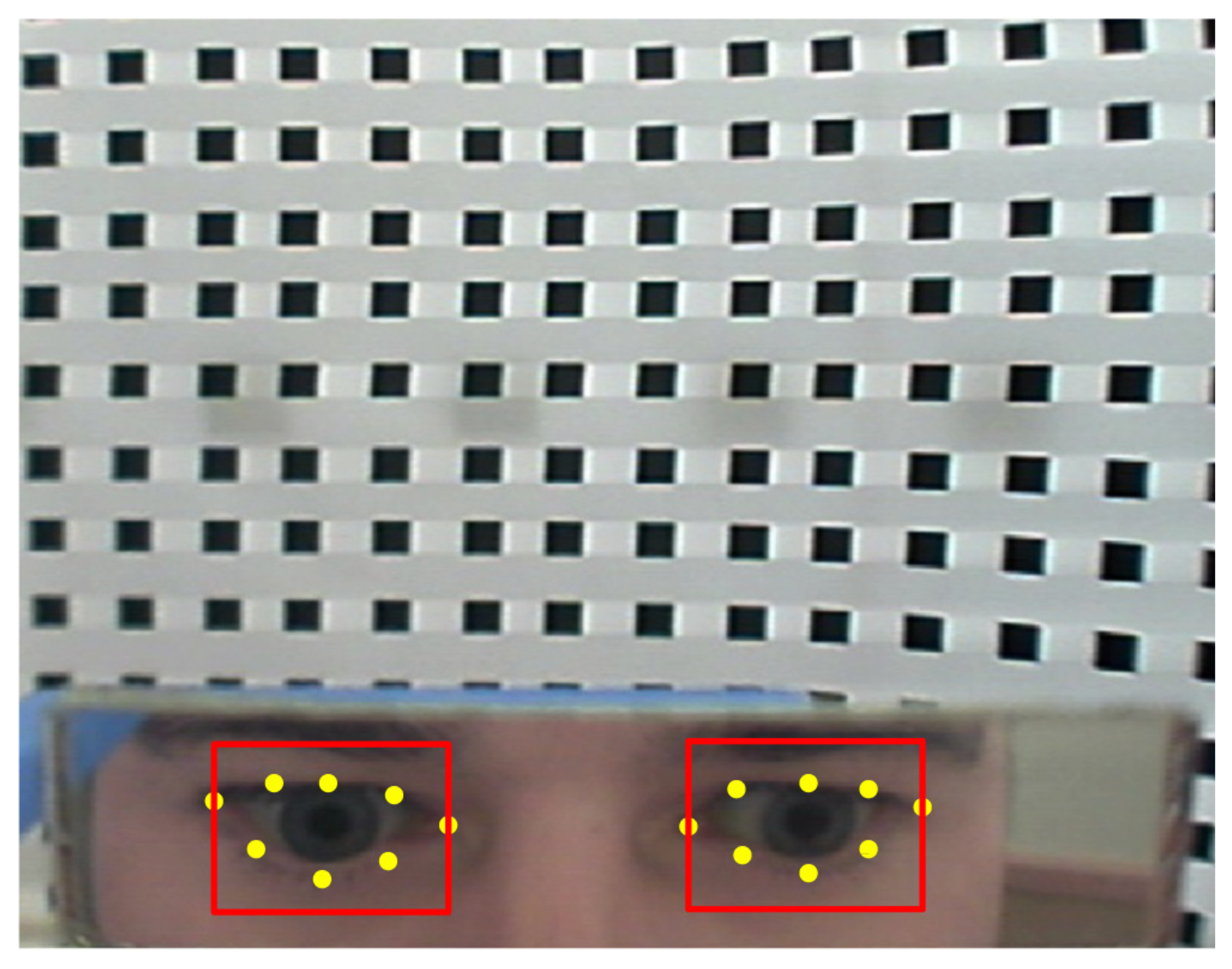
e) are determined. Moreover, both data with and without VOR contribution were collected and compared. The second session was organized into two phases. During the first phase the subjects were invited to look at the central point of the calibration plane (
C point in the
Figure 14), initial condition, and to the other calibration points with their eyes indicated by the numbers, in an arbitrary order (
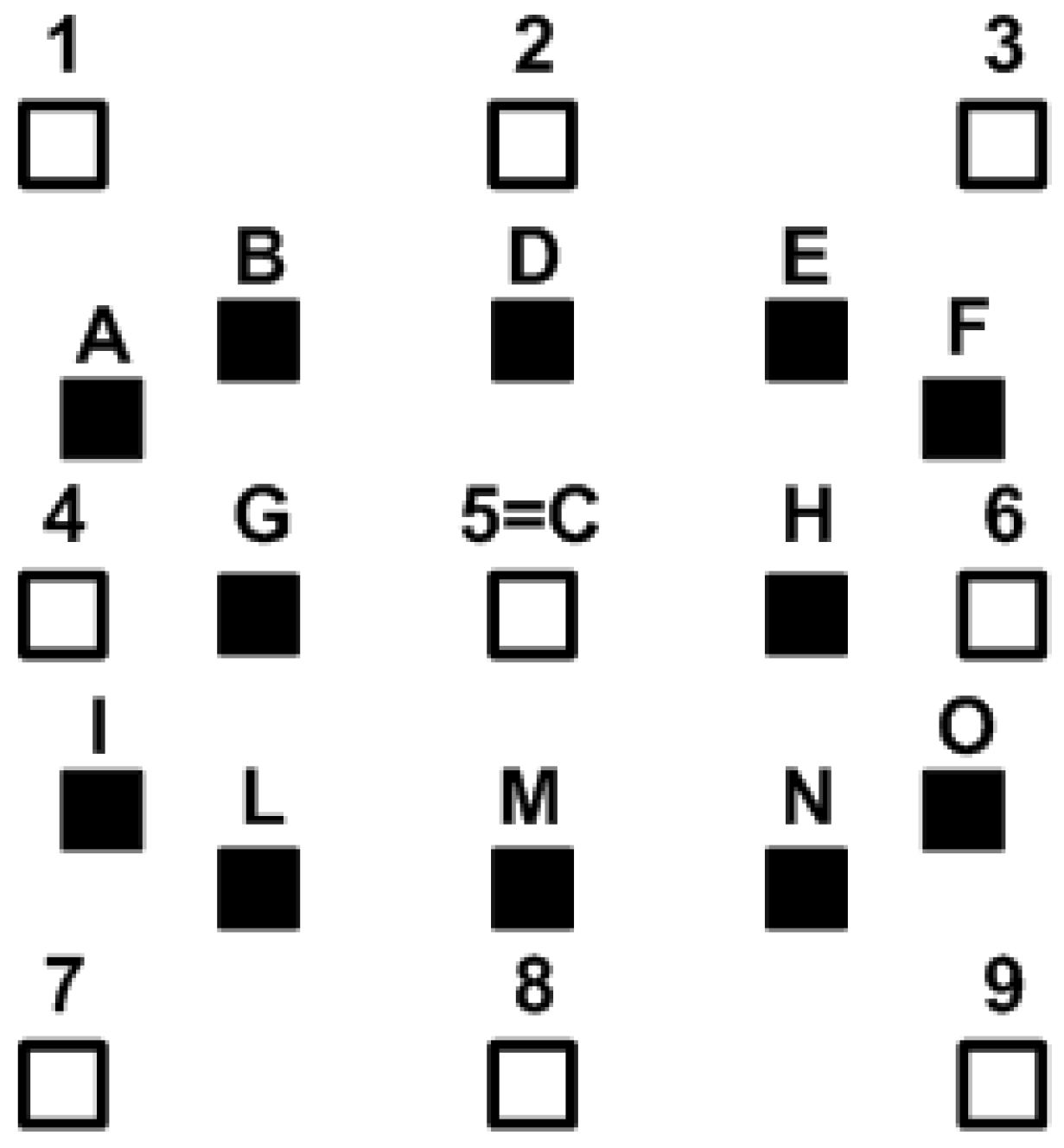
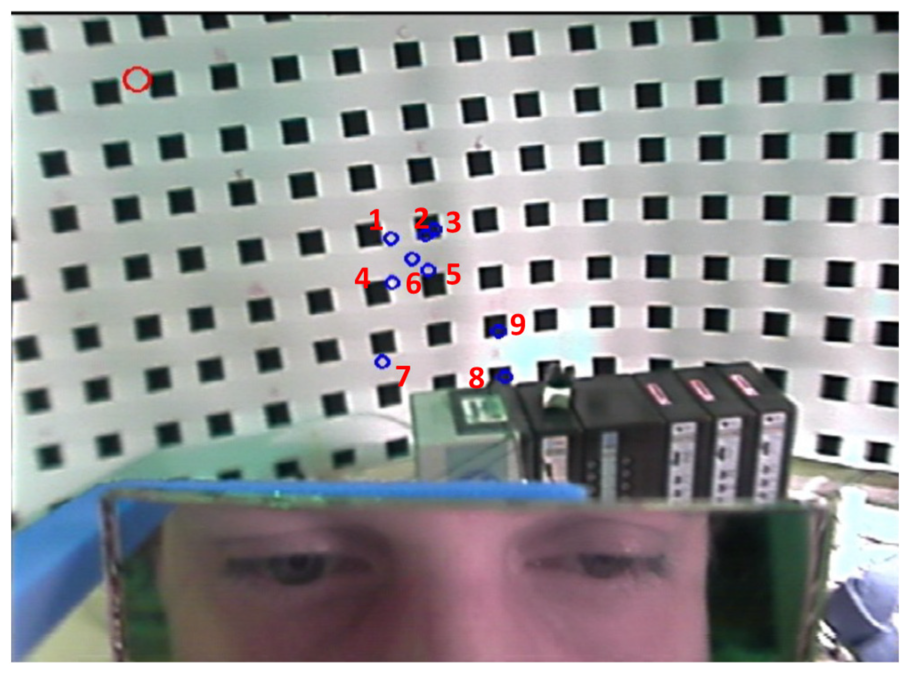
Figure 14). Simultaneously, the experimenter marked the corresponding point seen on the image plane. In the second phase, the subjects were invited to follow the square indicated by letters with their eyes. This second phase was performed in two configurations. The first configuration was carried out with a chin support, where the head was completely still. Afterwards, the second configuration was conducted without any support, so the head was free-to-move. The results of the two configurations were statistically compared.
VR Estimation. Eleven subjects were enrolled for the 3D VR scenario experiment. Our VR application consists of an immersive room equipped with a number of sensors and effectors including three projection screens, a sound system, and a tracking system (
Figure 15). The subjects were asked to wear the system and, after the calibration phase, to freely walk around the room looking at the three screens. A total number of 10 circles were shown one by one in a random order and unknown position (see
Figure 15). The whole experiment duration was of 10 min for each subject. During the calibration phase the head movement correction was performed. The accuracy of the system was calculated in terms of median of angular errors between the circle positions and the estimated eye position across all the subjects, Moreover, a statistical comparison was performed between the accuracy results in the laboratory and in the VR conditions.
Experimental results
In this section we report on the achieved results for both experimental setups.
Accuracy estimation
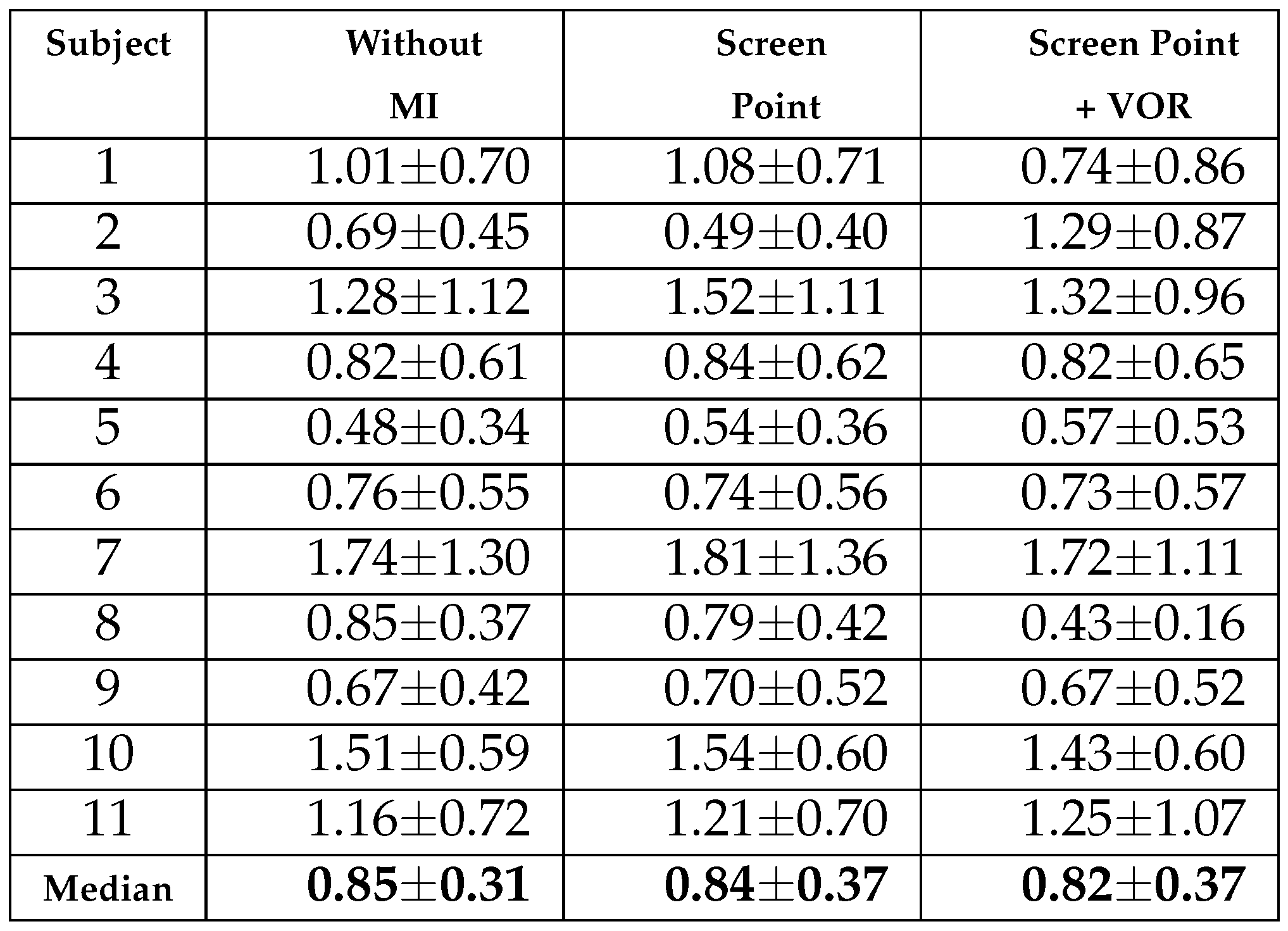
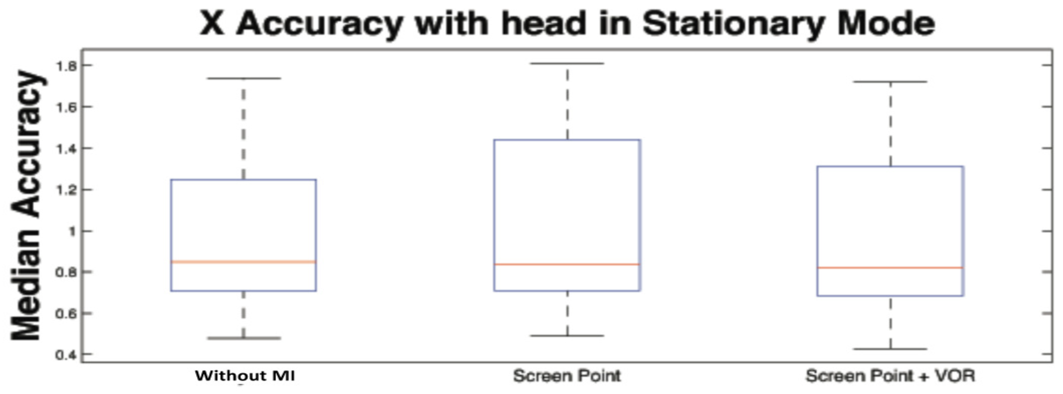
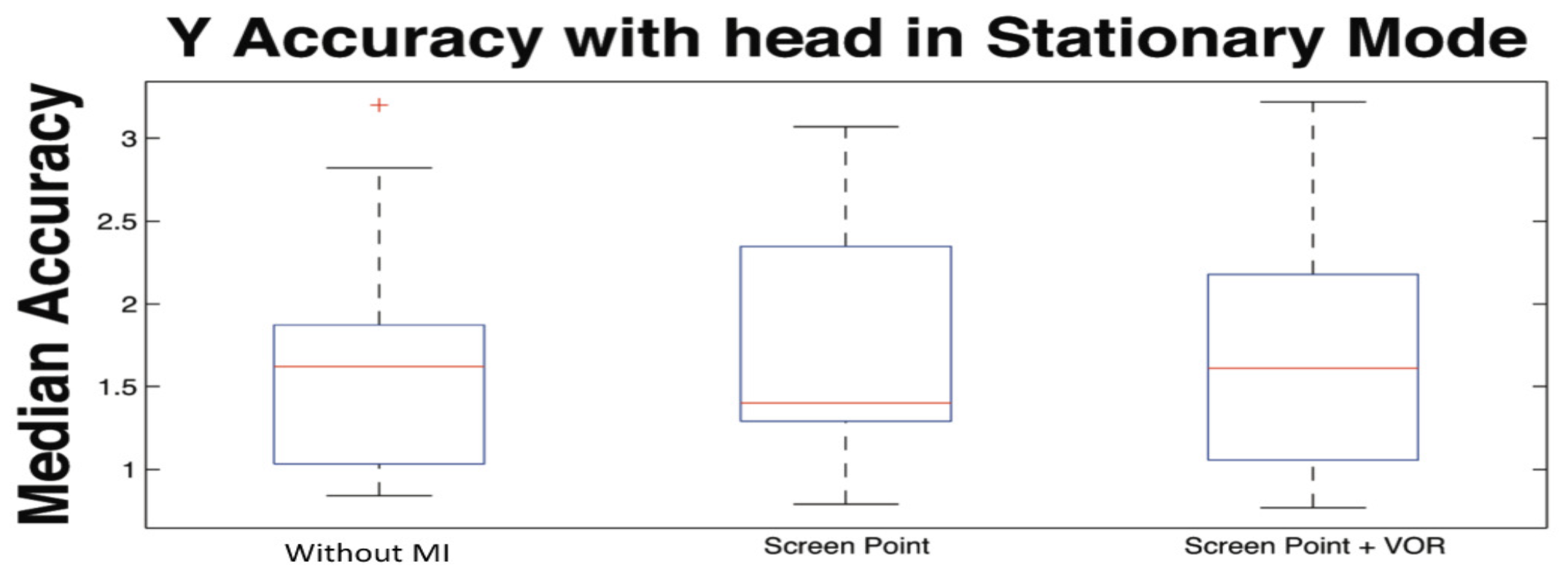
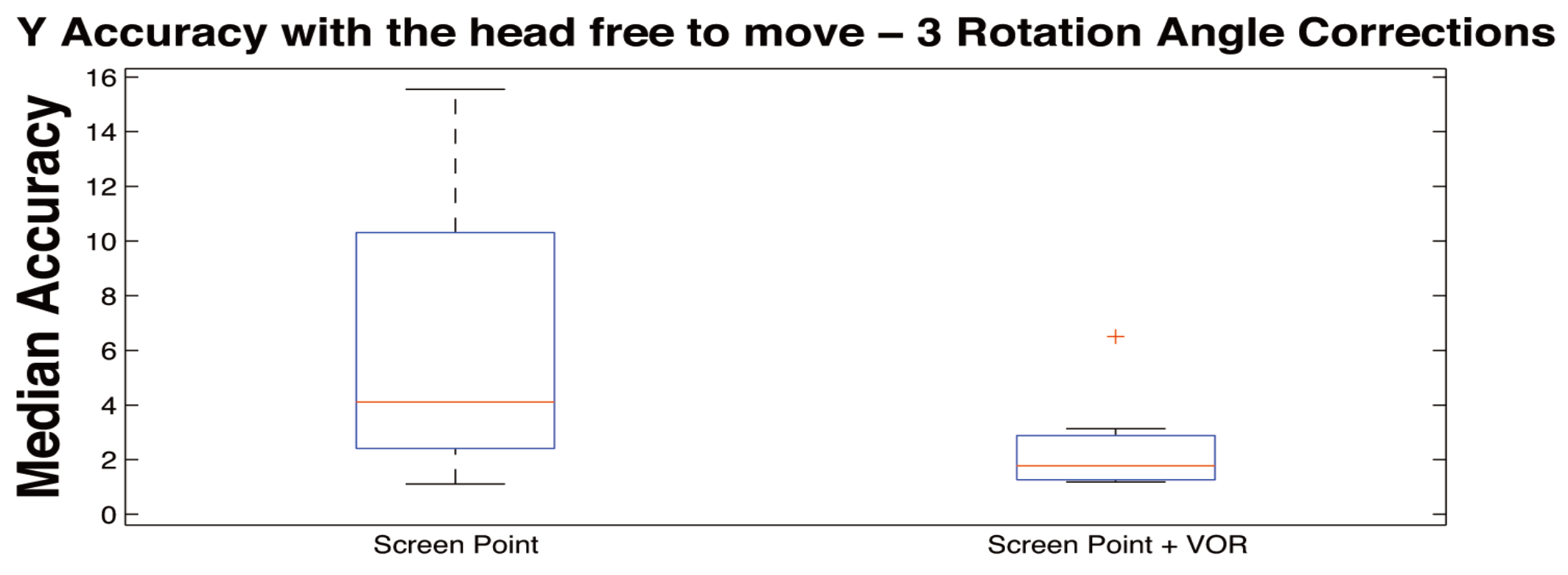
Here, the computation of the VOR curves as well as the computation of the accuracy of the system along x, and y axes were computed in terms of angular error. In particular, by means of the angular error, we evaluated the effect of the correction process comparing the gaze point in three different “modalities”. Specifically, the first was computed when the head was completely still, making use of a chin support (hereinafter called Stationary Mode), the second and third were performed without any support. More specifically, the second was computed applying only the integration of the calibration plane orientation changes (hereinafter called Screen Point), and the third was obtained applying both the integration of plane orientation changes and VOR contribution (hereinafter called Screen Point + VOR).
Table 1 reports average gain and standard deviation of VOR for both vertical (θ) and horizontal (ψ) axes.
These values were then used as gain corrections to estimate the specific offset for each subject. The accuracy, as mentioned above, was calculated in terms of median and median absolute dispersion of the gaze error, i.e., the error between the real observed position and the estimated value in pixels (
epixel), then transformed in degrees according to the equation 19
where
dpixel represents the distance between the subject and the calibration plane.
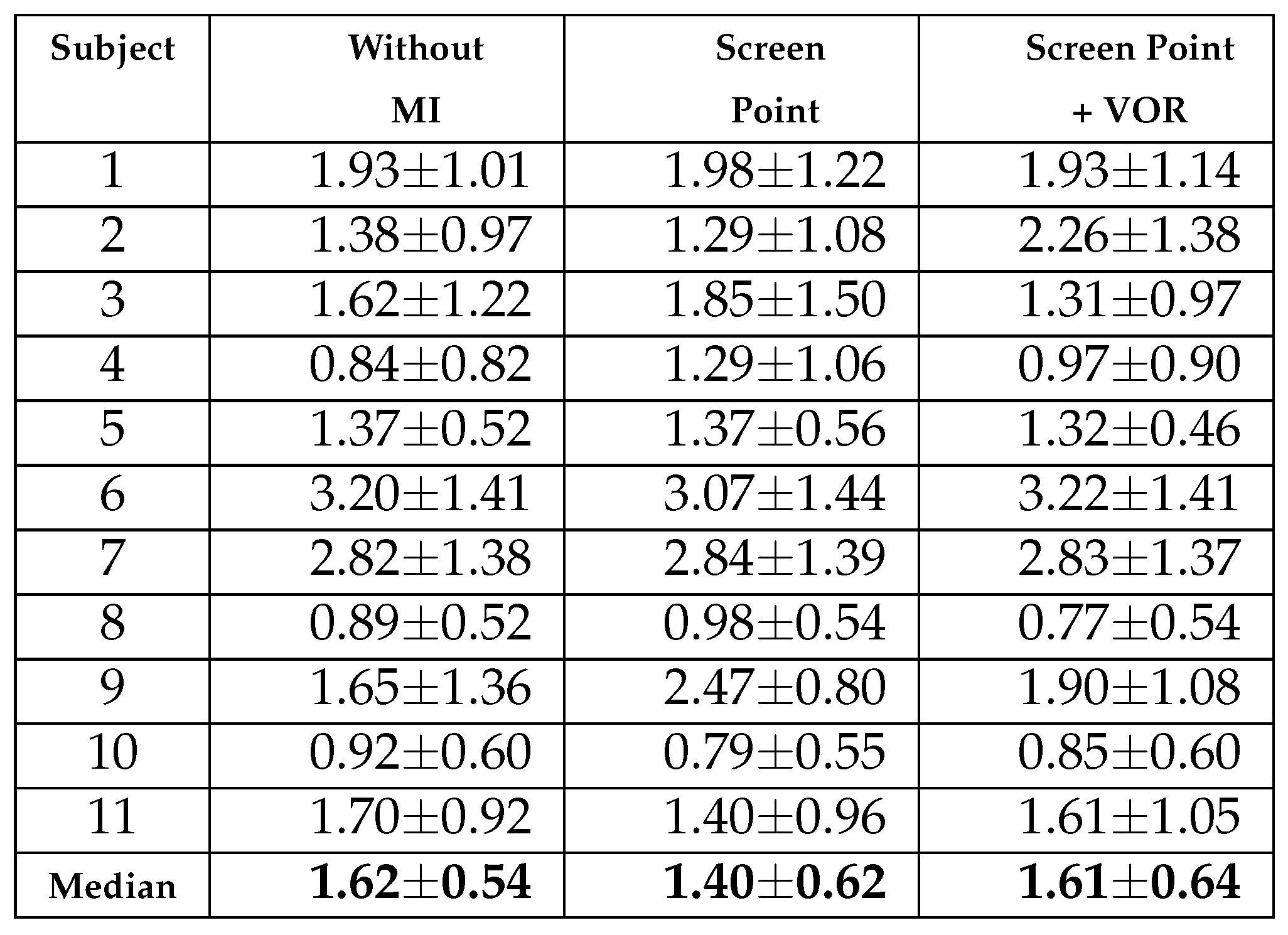
Table 2 and
Table 3 show median and median absolute dispersion of errors per subject, expressed in degrees, in stationary head condition for
x and
y axes (similar information are shown from the
Figure 16 and
Figure 17). In particular, the first column refers to the values without any correction, the column
Screen Point is referred to the error values, in the image plane, with the correction of the calibration plane orientation only actuated by IMU, and the column
Screen Point +
VOR is referred to the values, in the image plane, with the MI of both calibration plane orientation and VOR together. The corrections are reported for three head rotation angles θ, ϕ, and ψ.
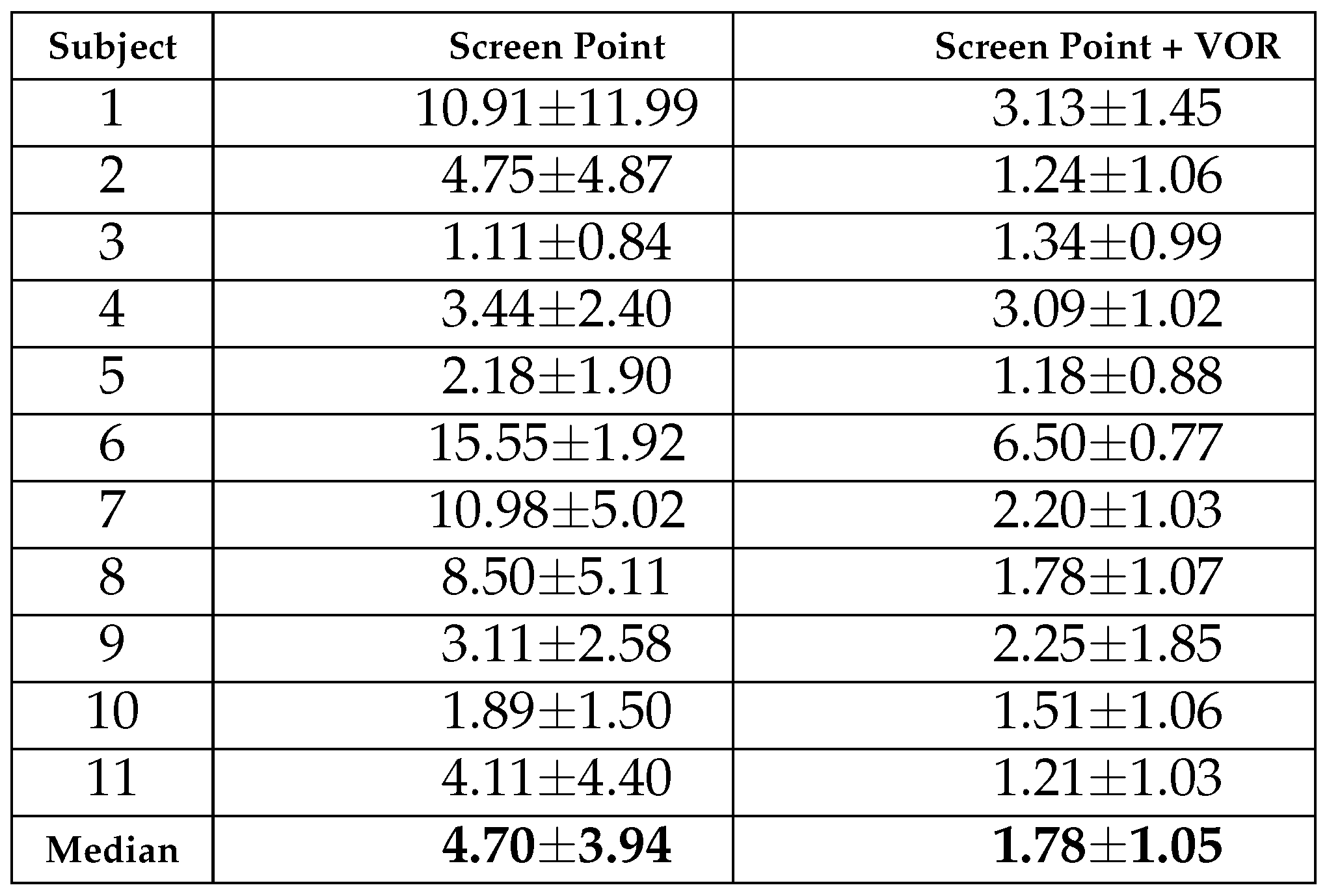
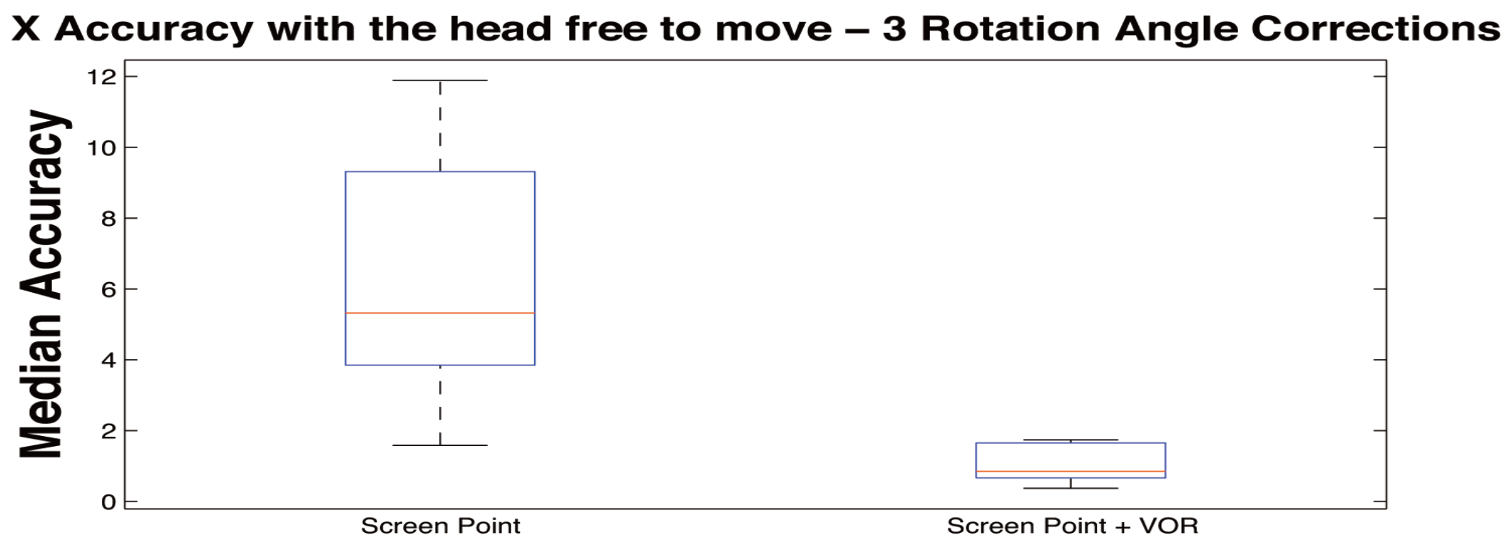
Table 4 and
Table 5 show median and median absolute dispersion of errors per subject, expressed in degrees, with free head movement condition for
x and
y axes (the same information cane seen in
Figure 18 and
Figure 19). In these Tables the columns report only the values for the column
Screen Point, which refers to the error values applying the correction of the calibration plane orientation and the column
Screen Point +
VOR, which is referred to the values applying the correction of both calibration plane orientation and VOR together. In these Tables the corrections are reported for 3 head rotation angles θ, ϕ, and ψ. The head movements were related to an average rotation amplitude of 20 degrees around the three axes.
Table 4 and
Table 5 do not report the column “Without MI”, with respect to
Table 2 and
Table 3 because the calibration process in case of head movement cannot be computed. More specifically, calibration would produce wrong random values by chance. As a matter of fact,
Figure 20 reports an example of calibration during head movement. In this figure, it can be noticed that calibration points are strictly concentrated on a small part of the image plane making the system completely unusable.
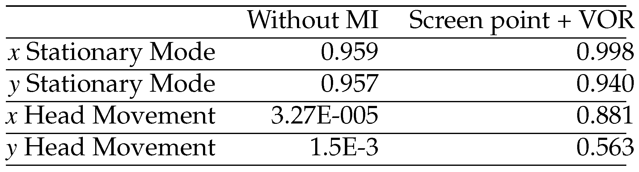
Table 6 show results from Friedman non para-metric test applied to stationary head (stationary) and head free to move (movement) conditions, with and without MI. More specifically, the test returns the probability that the different samples were not belonging to the same population. A pairwise comparison was performed for every pair of samples after the rejection of the null hypothesis carrying out a Mann-Whitney test with a Bonferroni adjustment. Results show that in Stationary mode the error between actual and computed coordinates of the gaze point estimated with and without MI are statistically equivalent, while when the head is moving the errors belong to different populations when MI (Screen + VOR) is not used. On the contrary, after the integration of the head movement, the statistical analysis reported that no significant difference is achieved among median in stationary head (stationary) and head free to move (movement) conditions.
VR estimation
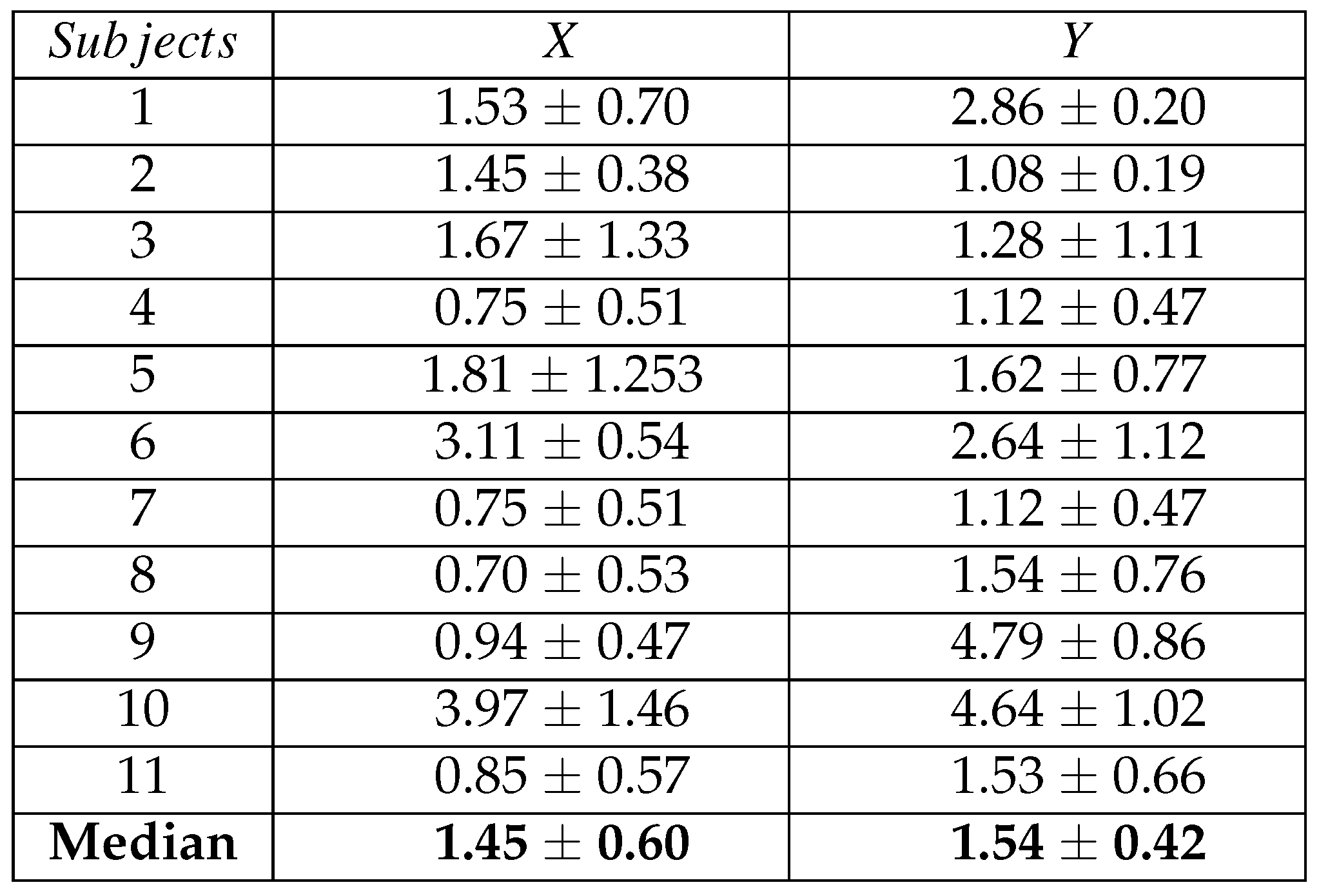
Results achieved in the VR scenario are reported in
Table 7 and are expressed in terms of angular errors along the
X and
Y axes. The Table shows for each subject the median
± the median absolute value of the angular errors computed on the gaze points of the 10 circle targets. The last raw represents the inter-subject median angular error, which resulted to be equal to 1.45 degree for the X coordinate and 1.54 degree for the Y coordinate. Moreover, a statistical comparison between the results achieved in laboratory and virtual reality conditions was performed by means of a Mann-Whitney test. For both coordinates, no significant differences were found between the two experimental setup conditions (X p-value
> 0.05 Y p-value
> 0.05) confirming the usability of the HAT-Move even in free-movement conditions.
Real-time estimation
The execution time of the main tasks and the entire software integrated into the system was about of 34.47 ms. The working frequency is about 29 Hz, which is greater than camera sampling frequency (25Hz), therefore the real-time requirement was fulfilled. ¡
Discussion and conclusion
Even though many current HMEGT systems are used without any integration of the movement of the head either for image plane orientation nor for the Vestibulo-Ocular Reflex, they are used with partial head movements. This study pointed out that HMEGT systems are strongly affected by head movements. More specifically, when the chin support is used the angular errors are acceptable. This conclusion is supported by the literature and also confirmed by this study, see
Figure 16 and
Figure 17, and
Table 2 and
Table 3. Indeed, no strong divergence between the median values for both errors along
x and
y is present, and confirmed by Friedman nonparametric test for paired sample with
Bon f erroni post-hoc correction for multiple comparison reported in
Table 6 no significant difference is shown for stationary mode. However, the same statistical tests highlighted that when head slightly moves the errors dramatically increase. It is worthwhile noting that the multiple comparisons reported in figures showed that during head movements the gaze point diverge with errors of 4–5 degrees. This experimental evidence suggests that the proposed corrections are essential to achieve an accurate eye gaze tracking in dynamical conditions. In fact, since eye tracking systems are often used also in medical environments for detecting pathologies which can range from behavioral to neurological fields, these errors could bring to misleading interpretations. The effectiveness of the head movement integration has been proven by the statistical comparison on
x and
y directions. In fact, it is possible to reduce the angular errors achieving no statistical difference between stationary mode and head movements, showing that the system keeps the same accuracy in both modalities. The estimated median error with head movement is reduced from 5.32° with a standard deviation of 2.81° (without VOR correction) to 0.85° with a standard deviation of 0.44° and from 4.70° with a standard deviation of 3.94° (without VOR correction) to 1.78° with a standard deviation of 1.05° for
x and
y axes, respectively. The obtained accuracy results confirm the reliability and robustness of the proposed system.
Moreover, the difference between the accuracy along x and y can be due to angular position of the camera (which is above of the eyes) which reduces the accuracy of the vertical positions of the pupil. In addition, this system fulfilled the realtime requirement being the execution time of the algorithm lower than the time interval between two consecutive video frames. In order to test the system even in conditions in which the subject was completely free to move and walk, we have developed an experiment in a virtual reality environment. We asked the subjects to look at random points on the screen of the VR moving into the room. Accuracy resulted to be equal to 1.45 degree for the X coordinate and 1.54 degree for the Y coordinate. No significant differences were found from the accuracy in the laboratory conditions. This result confirm the robustness of the proposed system even in scenarios similar to real environments
The main limitation of the system is the low frame rate of the camera. This limitation does not allow the system to acquire fast saccadic movements, which are known to be in the time range of 30 ms, while it is able to acquire slow saccadic movements around 100 ms. The proposed system is equipped with low cost hardware and it results extremely lightweight, unobtrusive, and aesthetically attractive providing a good acceptability by the end users. Thanks to these properties and its technological specifications the HAT-Move system allows investigating how humans interact with the external environment continuously. This ecological approach (Bronfenbrenner, 1977) could be pursued either at individual or community level with the aim of analyzing and coding both activities and relationships. More specifically, this kind of information can be really useful in studying non-verbal social behavior in both healthy and impaired people (e.g., affected by behavioral pathologies such as autistic disorders) as well as to improve the scientific knowledge on human interpersonal relationships. Furthermore, HAT-Move system has been already shown to be useful for studying eye pattern as a response of emotional stimulation with good and promising results (Lanatà et al., 2013; Lanata, Armato, et al., 2011). As a matter of fact eye feature pattern could provide a new point of view in the study of personal and interpersonal aspects of human feelings. In such a way eye information which we already showed to be informative in emotional response, could be integrated with other sets of physiological data (Betella et al., 2013) such as cardiac information (Lanata, Valenza, Mancuso, & Scilingo, 2011) or heart rate variability (Valenza, Allegrini, Lanata, & Scilingo, 2012), respiration activity(Valenza, Lanatá, & Scilingo, 2013), as well as electrodermal response (Greco et al., 2012) in a multivariate approach (Valenza et al., 2014) in order to create a very complete descriptive set of data able to explain the non-verbal phenomenology behind implicit (autonomic nervous system response) and explicit human response to external stimulation in real or virtual scenario (Wagner et al., 2013). It could be really helpful also in the investigation of several pathologies where the unobtrusiveness of the instrumentations could allow of monitoring naturally evoked response of participants, (Lanatà, Valenza, & Scilingo, 2012; Valenza, Lanata, Scilingo, & De Rossi, 2010; Lanatà et al., 2010; Armato et al., 2009; Valenza et al., 2010; Lanata, Valenza, et al., 2011). This latter issue could be used either on healthy participants or subject suffering from pathologies such as autism (Mazzei et al., 2012) as well as alterations of mood (Valenza, Gentili, Lanata, & Scilingo, 2013) etc. in which social skills are a strong impact on the lifestyle of it should improve the scientific knowledge on human interpersonal relationships, emotions etc. Moreover, to achieve these aims further efforts will be devoted to integrating a high-speed camera with high resolution in order to capture fast saccadic movements and to providing better accuracy. Moreover, an optimization process will be addressed to develop new multithreading algorithms based on the interocular distance in order to obtain a 3D eye tracking system.


