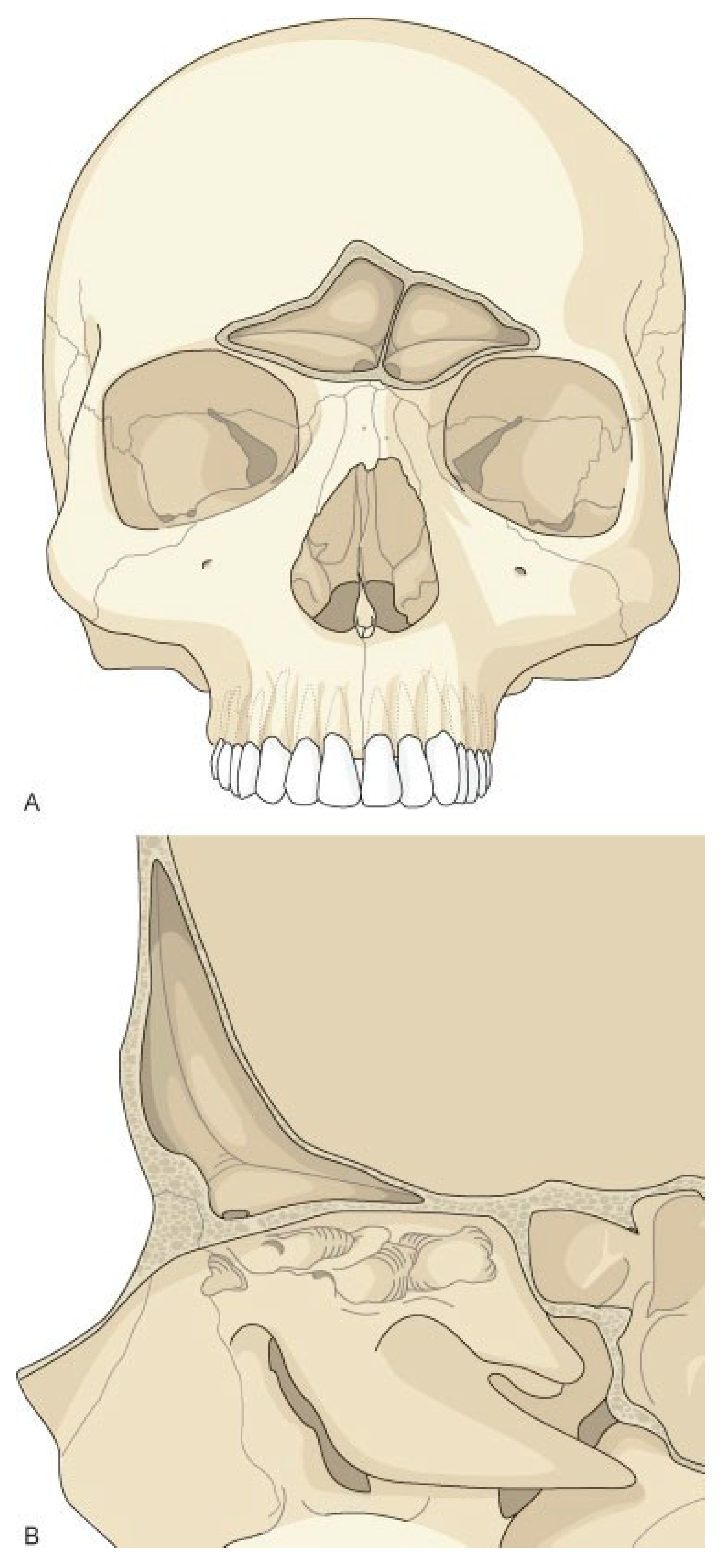
Figure 1.
Frontal sinus anatomy. The anterior table of the frontal sinus is thick bone and provides forehead contour. The posterior table is thinner and constitutes a portion of the anterior cranial fossa. The floor of the sinus makes up a portion of the orbital roof. The frontal sinus ostia is located in the medial, posterior, and inferior portion of the sinus floor.
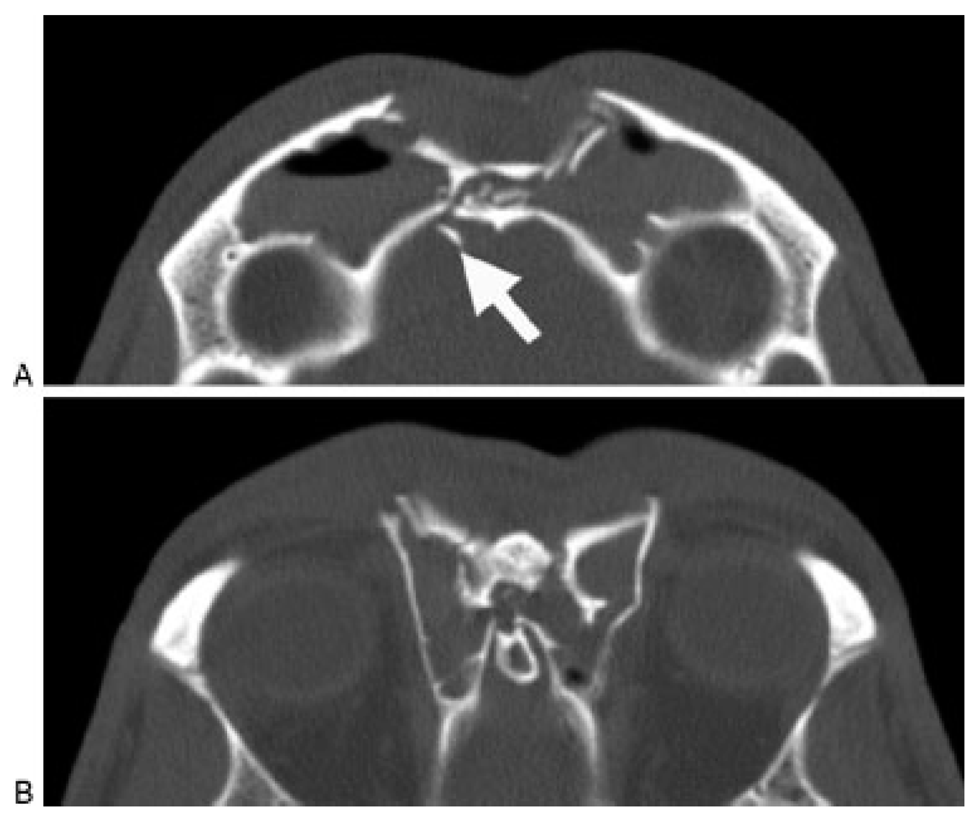
Figure 2.
Axial computed tomography scan demonstrating a frontal sinus fracture involving both the anterior and poster- ior tables. (A) Marked anterior table disruption. The white arrow points out a displaced posterior table bone fragment. (B) Disruption of the nasofrontal recess.
Figure 2.
Axial computed tomography scan demonstrating a frontal sinus fracture involving both the anterior and poster- ior tables. (A) Marked anterior table disruption. The white arrow points out a displaced posterior table bone fragment. (B) Disruption of the nasofrontal recess.
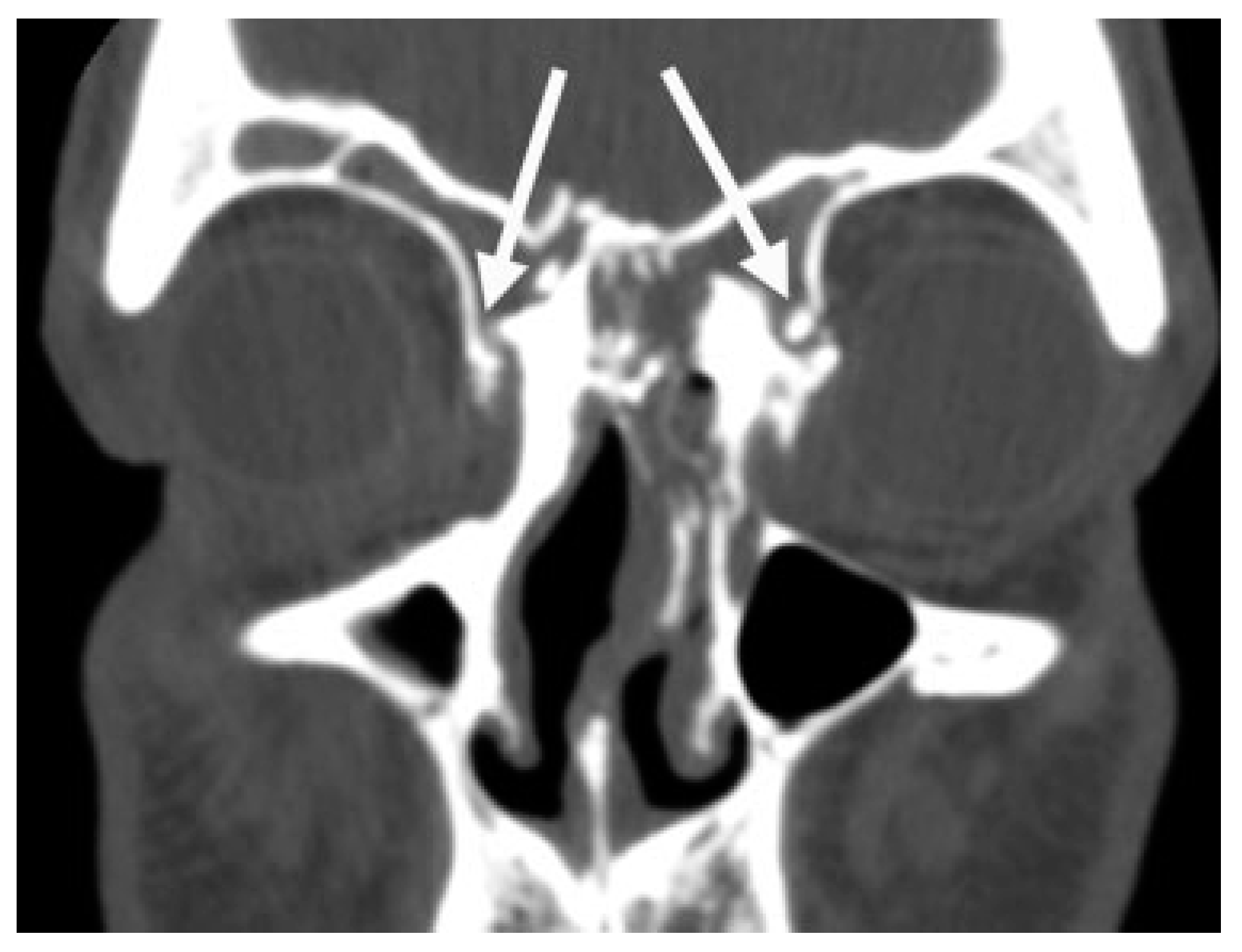
Figure 3.
Coronal computed tomography scan demonstrat- ing disruption of the medial orbit and frontal recess (arrows).
Figure 3.
Coronal computed tomography scan demonstrat- ing disruption of the medial orbit and frontal recess (arrows).
Figure 4.
Sagittal computed tomography scan demonstrat- ing a frontal sinus fracture. The arrow demonstrates narrow- ing and obstruction of the frontal sinus outflow tract.
Figure 4.
Sagittal computed tomography scan demonstrat- ing a frontal sinus fracture. The arrow demonstrates narrow- ing and obstruction of the frontal sinus outflow tract.
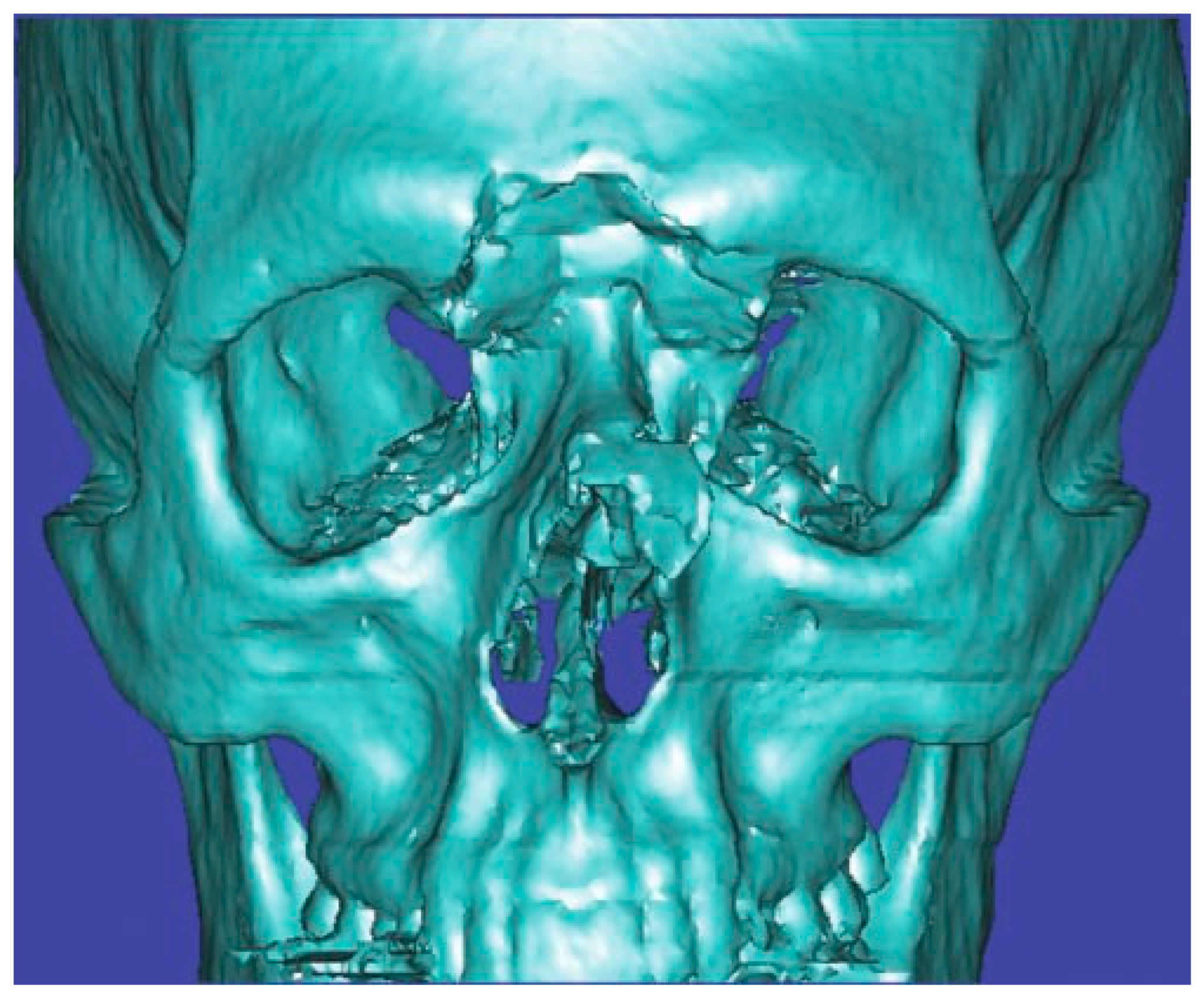
Figure 5.
Three-dimensional computed tomography scan of a frontal sinus fracture. The three-dimensional reconstruction can be helpful in delineating the location of fragments to be located intraoperatively as well as for patient/family education.
Figure 5.
Three-dimensional computed tomography scan of a frontal sinus fracture. The three-dimensional reconstruction can be helpful in delineating the location of fragments to be located intraoperatively as well as for patient/family education.
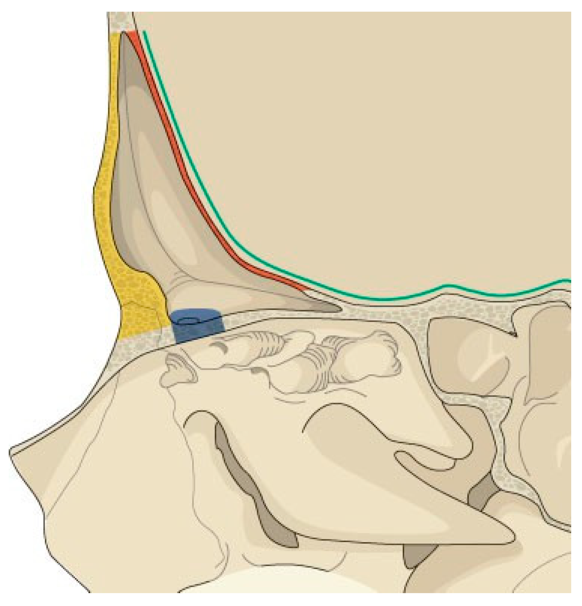
Figure 6.
Illustration of the anatomic parameters that need to be assessed when developing a treatment plan for frontal sinus fractures. Yellow, anterior table; red, posterior table; blue, frontal recess; green, dural integrity.
Figure 6.
Illustration of the anatomic parameters that need to be assessed when developing a treatment plan for frontal sinus fractures. Yellow, anterior table; red, posterior table; blue, frontal recess; green, dural integrity.
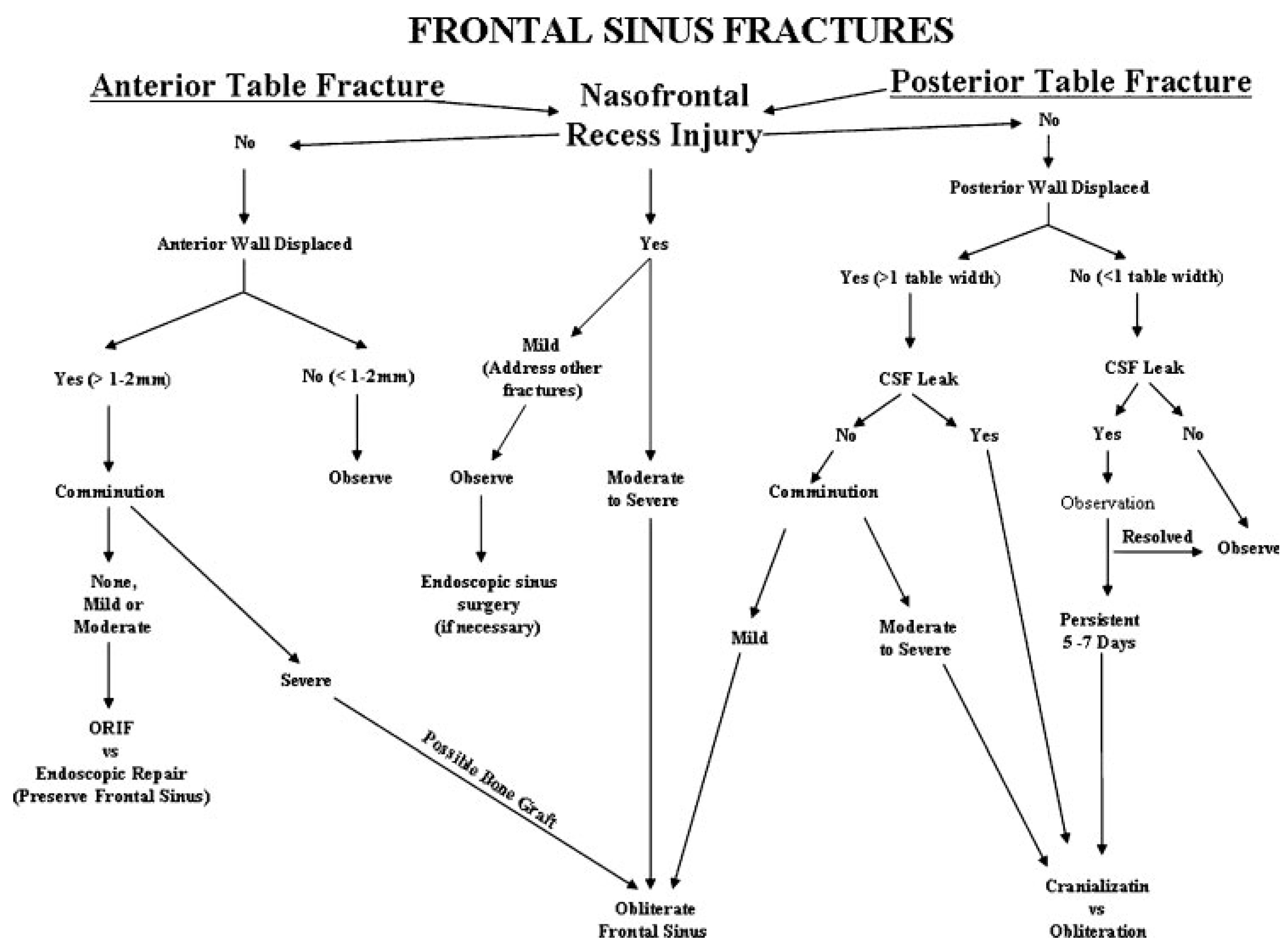
Figure 7.
Treatment algorithm for management of frontal sinus fractures. The algorithm is based on five anatomic parameters: anterior table fracture, posterior table fracture, frontal recess injury, dural integrity, and fracture comminution.
Figure 7.
Treatment algorithm for management of frontal sinus fractures. The algorithm is based on five anatomic parameters: anterior table fracture, posterior table fracture, frontal recess injury, dural integrity, and fracture comminution.
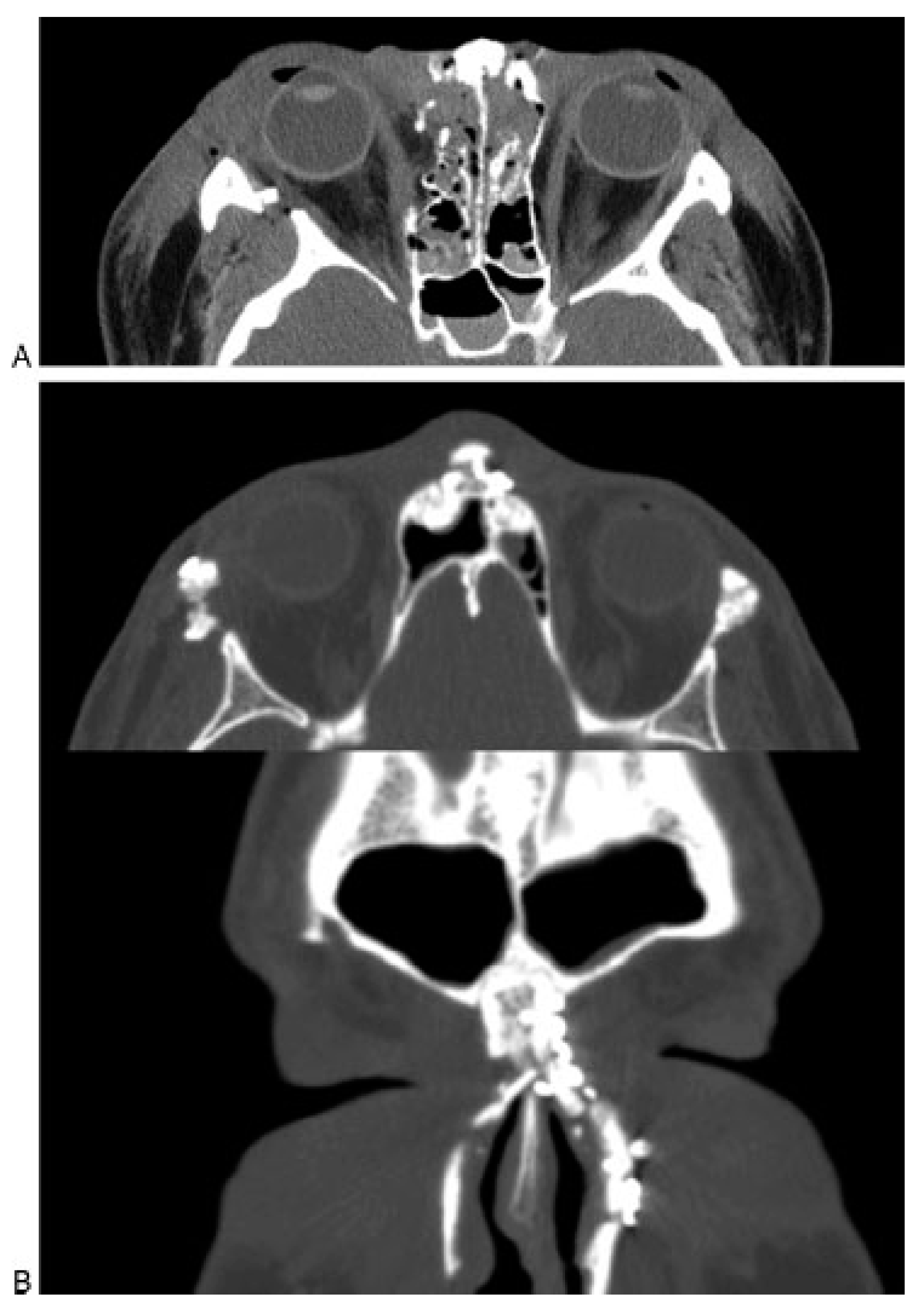
Figure 8.
(A) Axial computed tomography (CT) scan of an acute frontal sinus injury, showing partial disruption of the frontal recess. (B) Postoperative axial and coronal CT scan of the same patient demonstrating resolution of mucosal edema and patency of the frontal recess. The frontal sinus injury was observed and no frontal sinusotomy was per- formed.
Figure 9.
Incisions used for trephination of the left frontal sinus. Caution must be used to avoid injury to the supratro- chlear neurovascular pedicle.
Figure 9.
Incisions used for trephination of the left frontal sinus. Caution must be used to avoid injury to the supratro- chlear neurovascular pedicle.
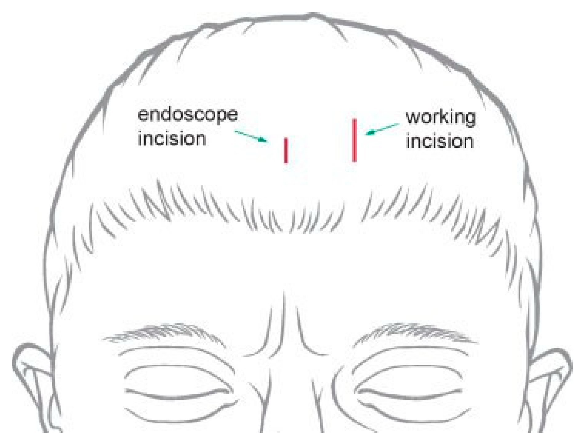
Figure 10.
Incisions used for endoscopic approach to the frontal sinus. The lateral ‘‘working incision’’ is larger and used for passing instrumentation and the implant. The medial incision is smaller and used to insert the endoscope.
Figure 10.
Incisions used for endoscopic approach to the frontal sinus. The lateral ‘‘working incision’’ is larger and used for passing instrumentation and the implant. The medial incision is smaller and used to insert the endoscope.
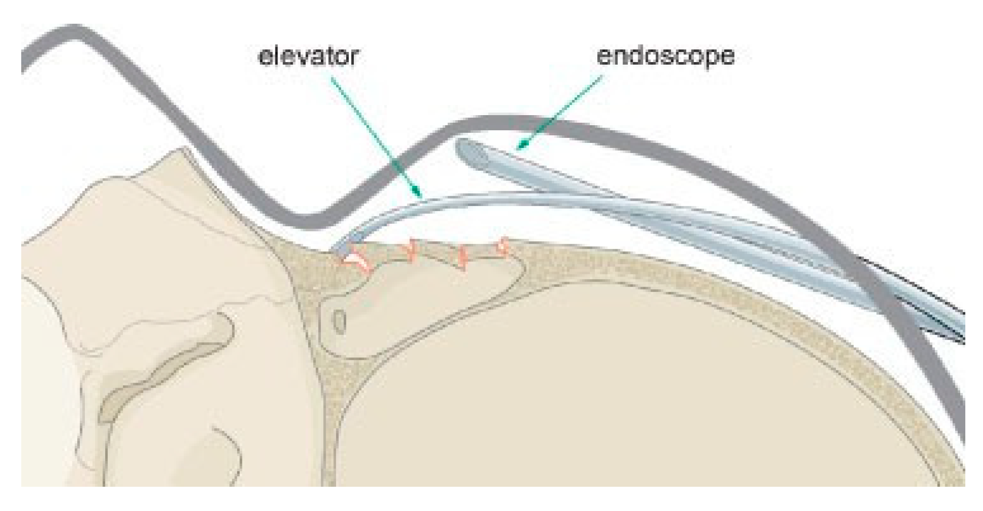
Figure 11.
Endoscopic exposure of a frontal sinus fracture.
Figure 11.
Endoscopic exposure of a frontal sinus fracture.
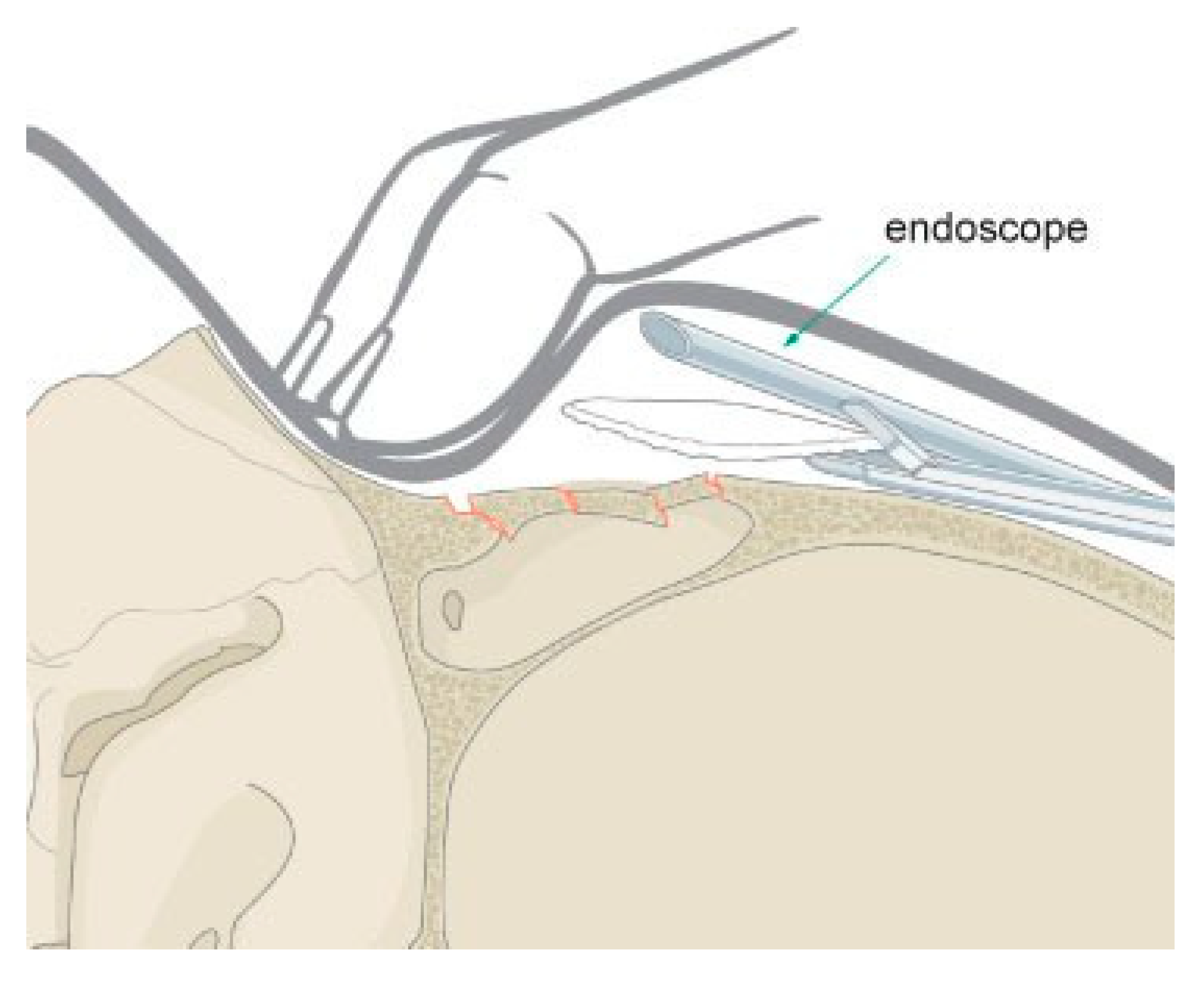
Figure 12.
Endoscopic insertion of a porous polyethylene implant to camouflage a frontal sinus fracture.
Figure 12.
Endoscopic insertion of a porous polyethylene implant to camouflage a frontal sinus fracture.
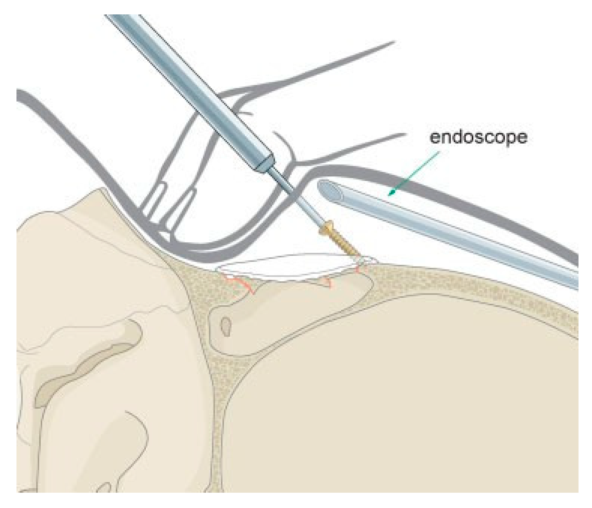
Figure 13.
Transcutaneous fixation of an endoscopically placed anterior table porous polyethylene implant. Self- drilling screws are used to avoid the need for a drill.
Figure 13.
Transcutaneous fixation of an endoscopically placed anterior table porous polyethylene implant. Self- drilling screws are used to avoid the need for a drill.
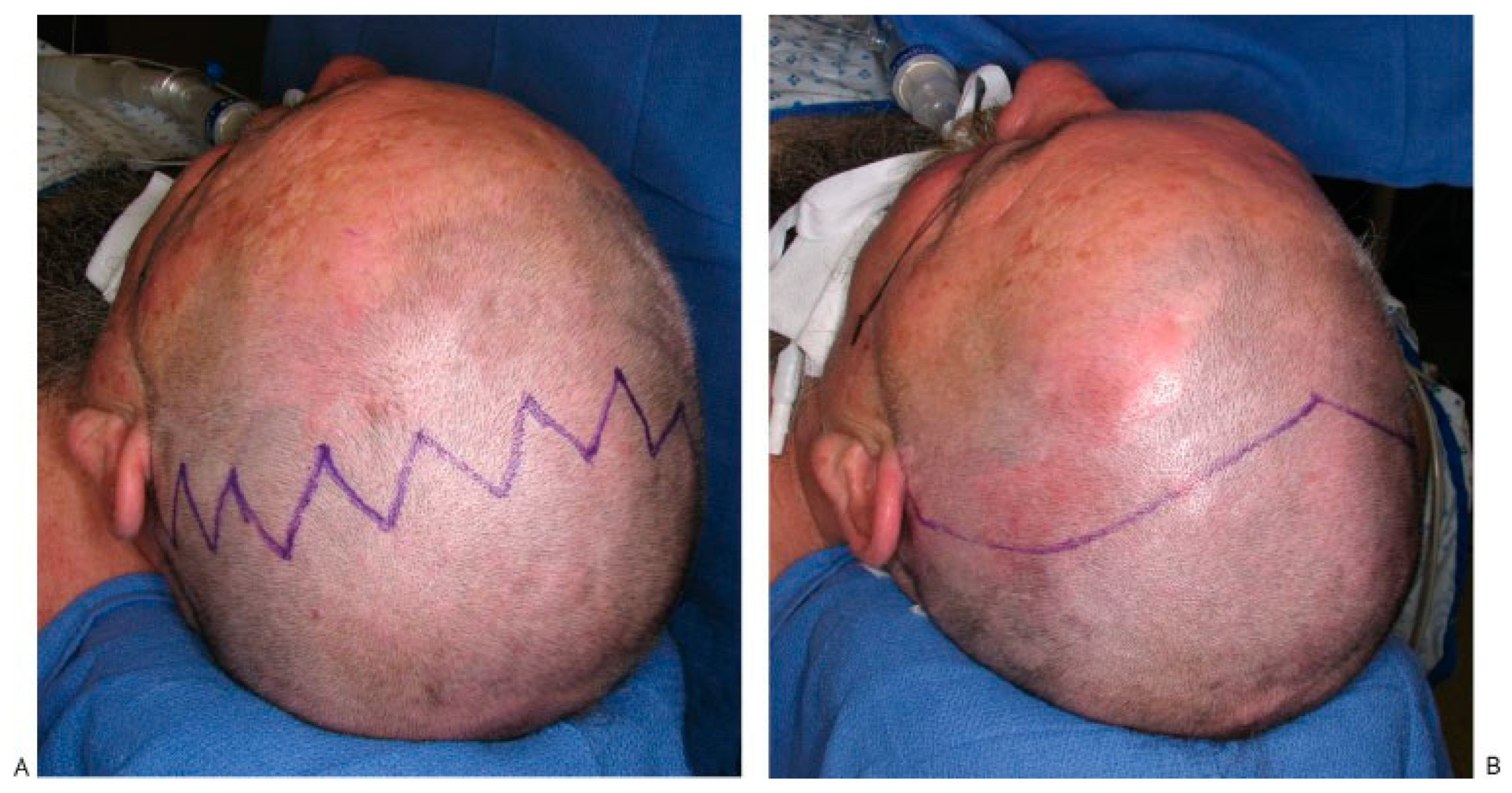
Figure 14.
(A) Typical zigzag coronal incision used when patients have longer hair that will fall down across the incision lines. (B) Traditional widow’s peak coronal incision used in patients with shorter hair.
Figure 14.
(A) Typical zigzag coronal incision used when patients have longer hair that will fall down across the incision lines. (B) Traditional widow’s peak coronal incision used in patients with shorter hair.
Figure 15.
Illustration of a right temporal dissection via a coronal approach. The surgeon must be very familiar with the anatomic layers of the temporal scalp to avoid injury to the temporal branch of the facial nerve.
Figure 15.
Illustration of a right temporal dissection via a coronal approach. The surgeon must be very familiar with the anatomic layers of the temporal scalp to avoid injury to the temporal branch of the facial nerve.
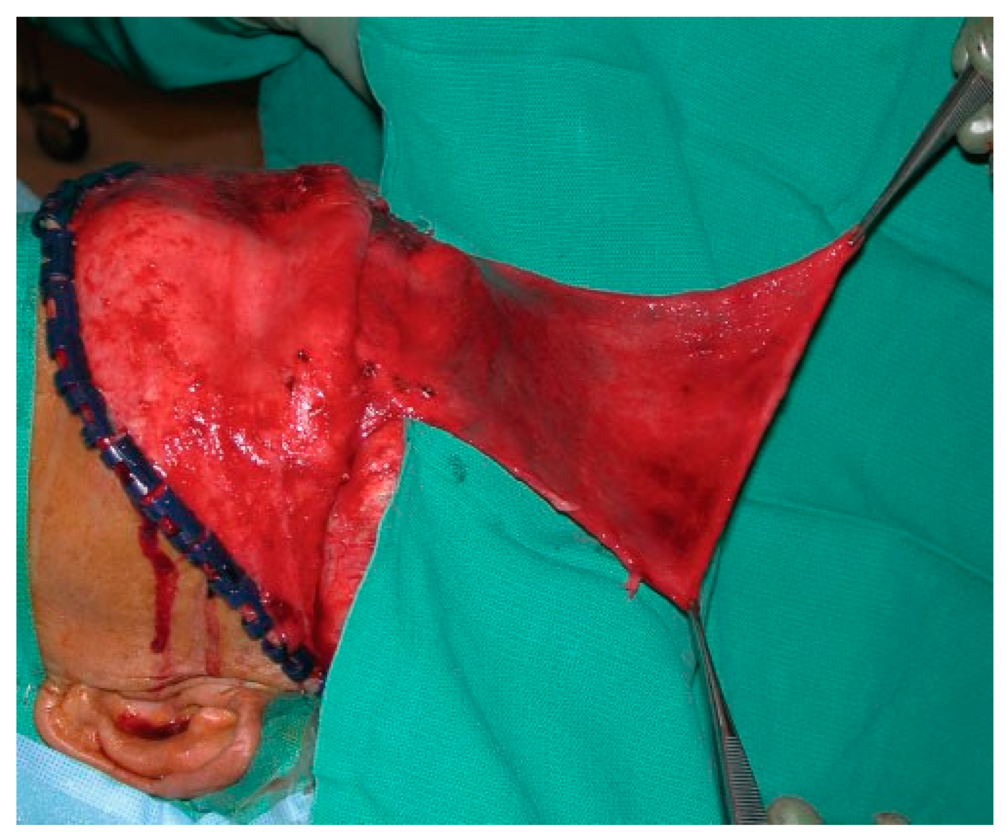
Figure 16.
Intraoperative photo of a large pericranial flap.
Figure 16.
Intraoperative photo of a large pericranial flap.
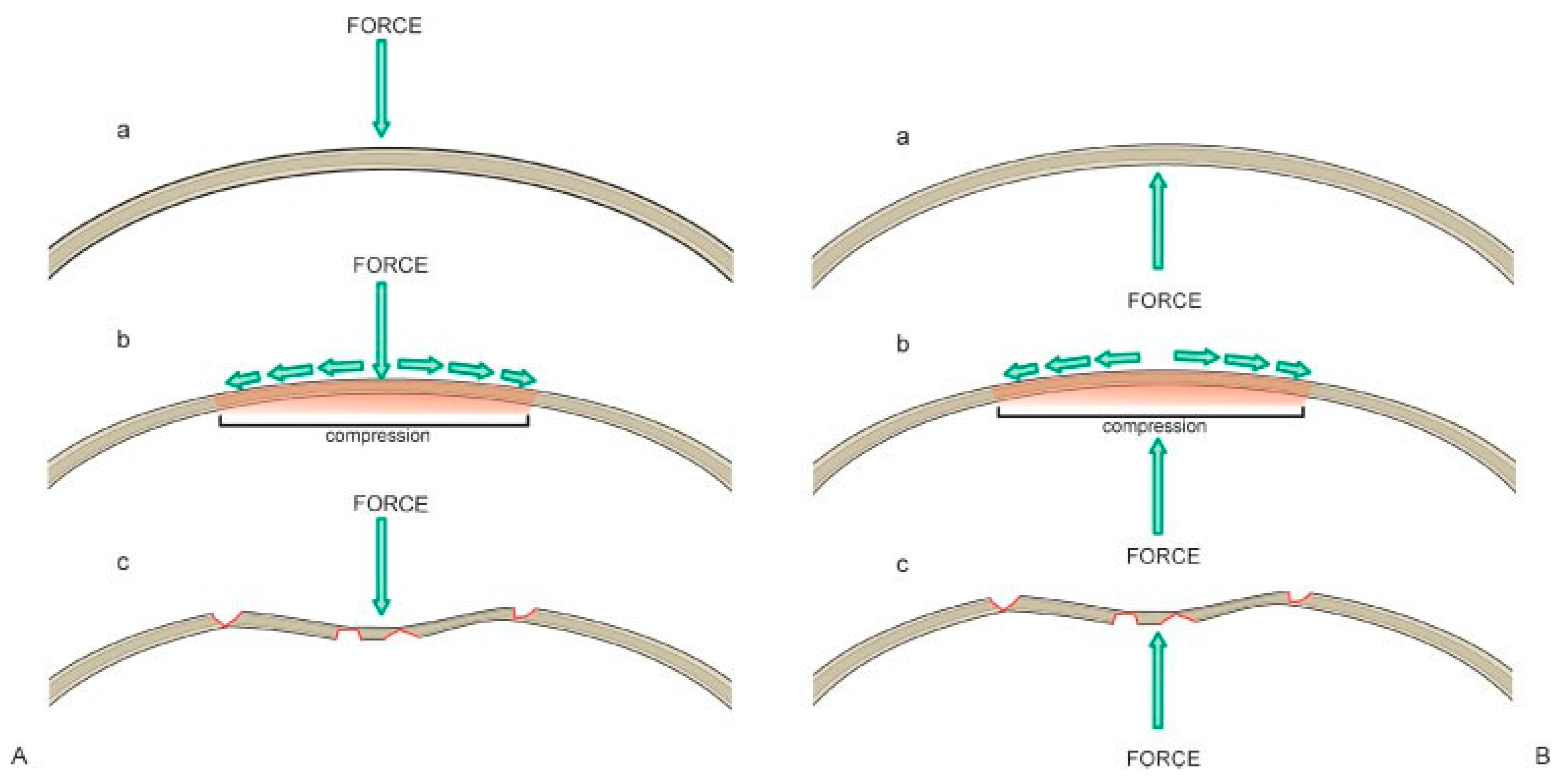
Figure 17.
(A) Illustration of the compressive forces on the frontal bone resulting from a frontal sinus fracture. (B) Illustration of the forces that must be applied to return the frontal bone to its premorbid convex shape.
Figure 17.
(A) Illustration of the compressive forces on the frontal bone resulting from a frontal sinus fracture. (B) Illustration of the forces that must be applied to return the frontal bone to its premorbid convex shape.
Figure 18.
Intraoperative photo of a suture used to resuspend the scalp and midface during closure of the coronal incision.
Figure 18.
Intraoperative photo of a suture used to resuspend the scalp and midface during closure of the coronal incision.
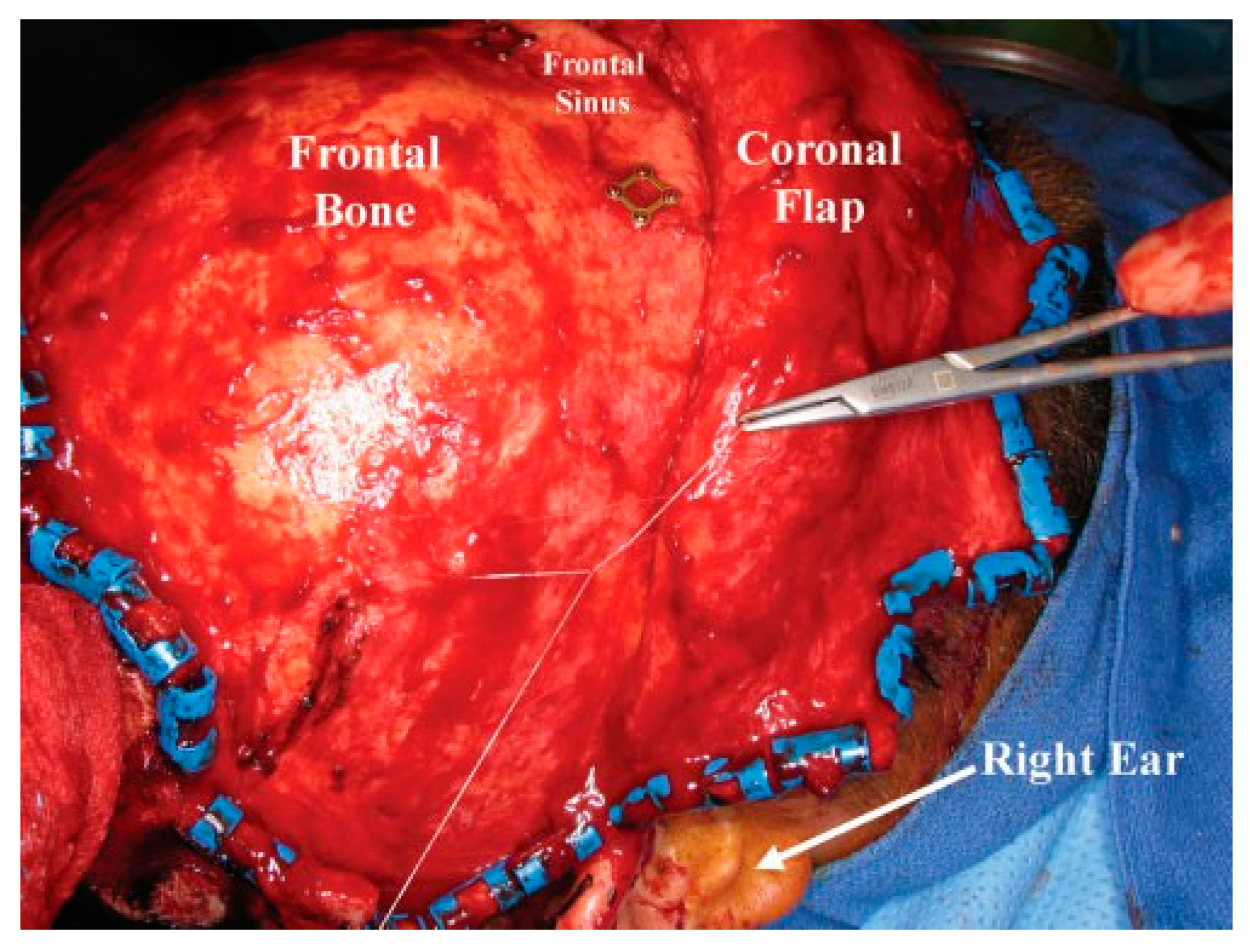
Figure 19.
Intraoperative photo demonstrating the use of bayonet forceps to outline the periphery of the frontal sinus.
Figure 19.
Intraoperative photo demonstrating the use of bayonet forceps to outline the periphery of the frontal sinus.
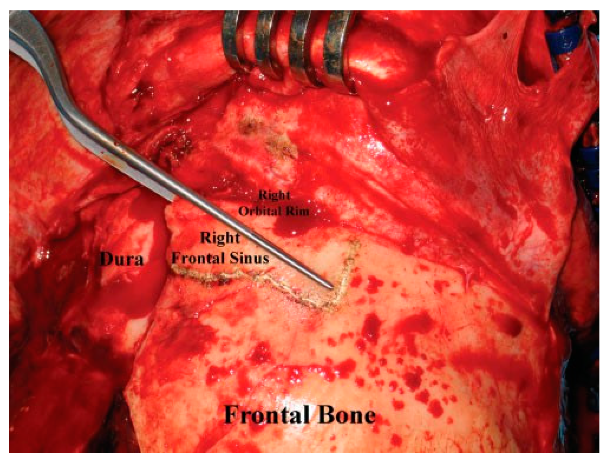
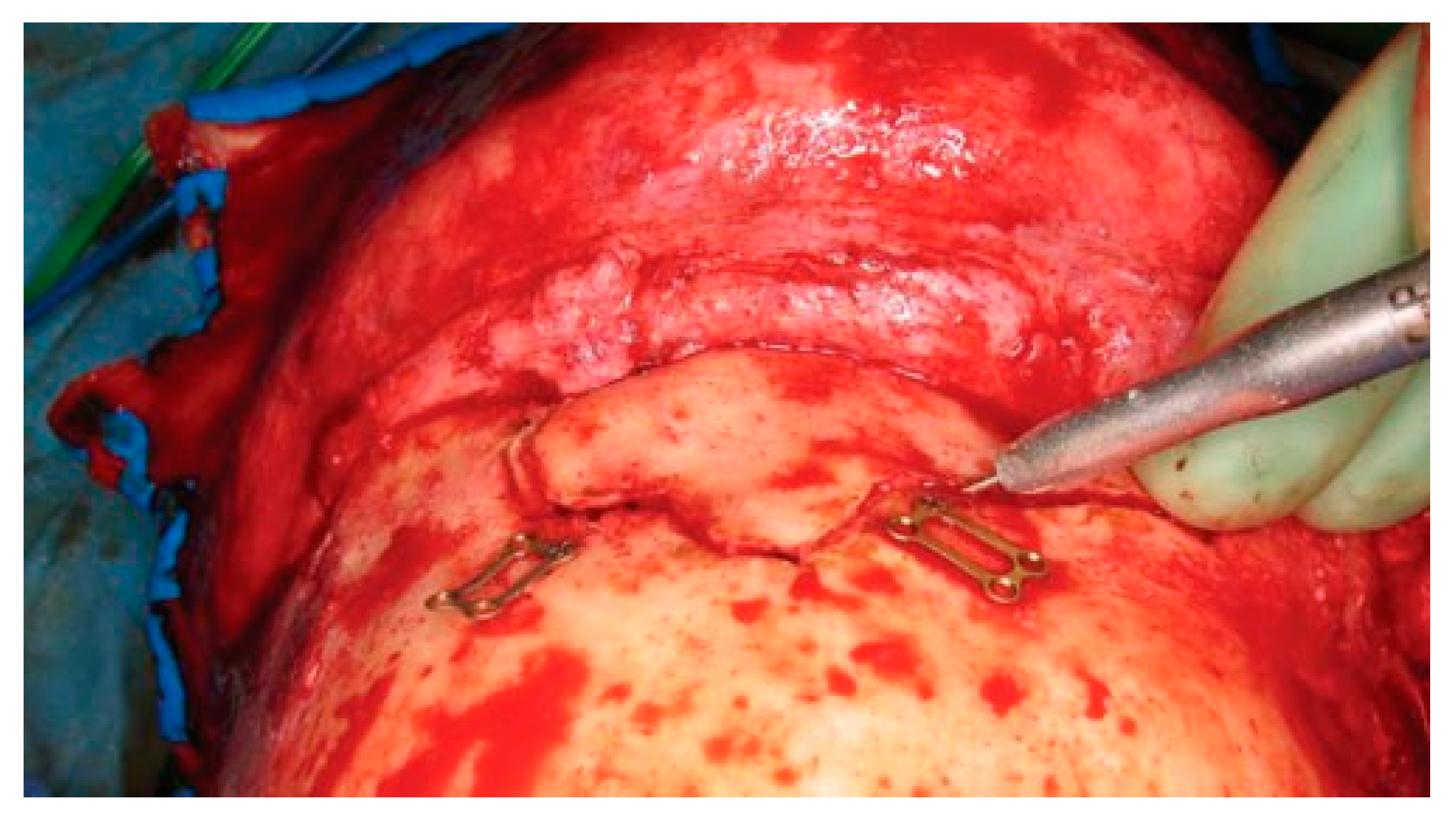
Figure 20.
Intraoperative photo of a frontal sinusotomy. The drill should be held at an angle to avoid entry into the intracranial cavity. Note that the plates used for fixation of the anterior table bone at the end of the procedure have been preapplied prior to the sinusotomy.
Figure 20.
Intraoperative photo of a frontal sinusotomy. The drill should be held at an angle to avoid entry into the intracranial cavity. Note that the plates used for fixation of the anterior table bone at the end of the procedure have been preapplied prior to the sinusotomy.
Figure 21.
Illustration highlighting the most difficult areas to completely remove the frontal sinus mucosa. Special attention must be given to these areas to avoid leaving remnants of sinus mucosa that will result in postoperative mucocele formation.
Figure 21.
Illustration highlighting the most difficult areas to completely remove the frontal sinus mucosa. Special attention must be given to these areas to avoid leaving remnants of sinus mucosa that will result in postoperative mucocele formation.
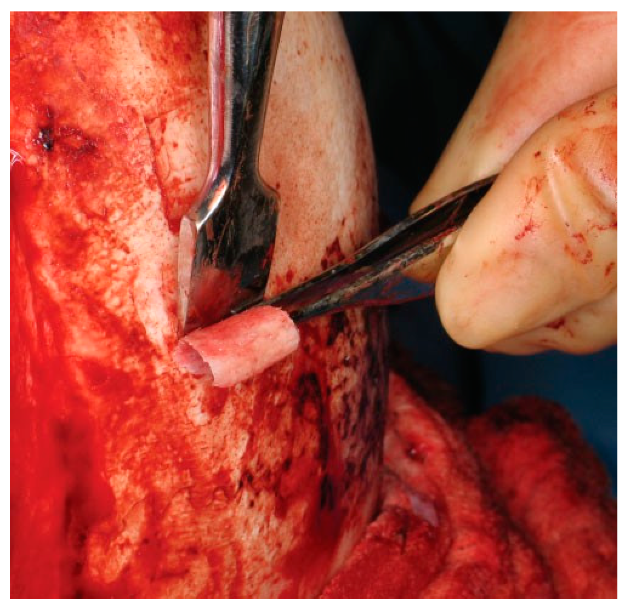
Figure 22.
Intraoperative photo of an outer table bone graft being harvested. The bone graft is then trimmed and positioned in the frontal recess to ensure separation of the nose and sinus.
Figure 22.
Intraoperative photo of an outer table bone graft being harvested. The bone graft is then trimmed and positioned in the frontal recess to ensure separation of the nose and sinus.
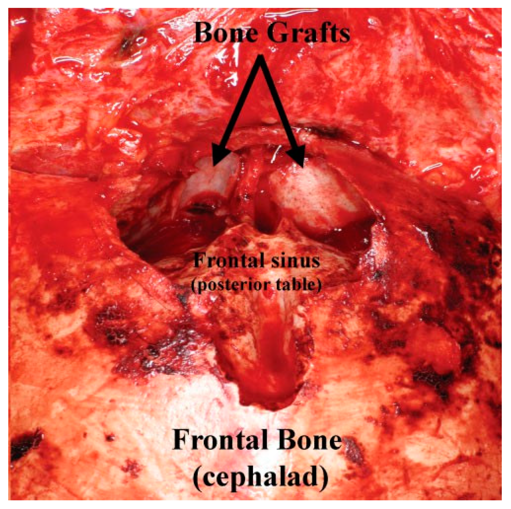
Figure 23.
Intraoperative photo of the bone graft (from
Figure 22) placed into the frontal recess to obstruct the frontal recess outflow tract.
Figure 23.
Intraoperative photo of the bone graft (from
Figure 22) placed into the frontal recess to obstruct the frontal recess outflow tract.