Article

A Low Temperature Growth of Cu2O Thin Films as Hole Transporting Material for Perovskite Solar Cells

by
Anna L. Pellegrino
1,*,
Francesca Lo Presti
1,
Emanuele Smecca
2,*,
Salvatore Valastro
2,
Giuseppe Greco
2,
Salvatore Di Franco
2,
Fabrizio Roccaforte
2,
Alessandra Alberti
2,* and
Graziella Malandrino
1,*
1
Dipartimento di Scienze Chimiche, Università degli Studi di Catania, INSTM UdR Catania, Viale Andrea Doria 6, 95125 Catania, Italy
2
National Research Council-Institute for Microelectronics and Microsystems (CNR-IMM), Zona Industriale Strada VIII No. 5, 95121 Catania, Italy
*
Authors to whom correspondence should be addressed.
Materials 2022, 15(21), 7790; https://doi.org/10.3390/ma15217790
Submission received: 6 October 2022 / Revised: 31 October 2022 / Accepted: 2 November 2022 / Published: 4 November 2022

Abstract

:
Copper oxide thin films have been successfully synthesized through a metal–organic chemical vapor deposition (MOCVD) approach starting from the copper bis(2,2,6,6-tetramethyl-3,5-heptanedionate), Cu(tmhd)2, complex. Operative conditions of fabrication strongly affect both the composition and morphologies of the copper oxide thin films. The deposition temperature has been accurately monitored in order to stabilize and to produce, selectively and reproducibly, the two phases of cuprite Cu2O and/or tenorite CuO. The present approach has the advantages of being industrially appealing, reliable, and fast for the production of thin films over large areas with fine control of both composition and surface uniformity. Moreover, the methylammonium lead iodide (MAPI) active layer has been successfully deposited on the ITO/Cu2O substrate by the Low Vacuum Proximity Space Effusion (LV-PSE) technique. X-ray diffraction (XRD), field emission scanning electron microscopy (FE-SEM), and atomic force microscopy (AFM) analyses have been used to characterize the deposited films. The optical band gap (Eg), ranging from 1.99 to 2.41 eV, has been determined through UV-vis analysis, while the electrical measurements allowed to establish the p-type conductivity behavior of the deposited Cu2O thin films with resistivities from 31 to 83 Ω cm and carrier concentration in the order of 1.5–2.8 × 1016 cm−3. These results pave the way for potential applications of the present system as a hole transporting layer combined with a perovskite active layer in emergent solar cell technologies.

Graphical Abstract

1. Introduction

Recently, copper-oxide compounds represent one of the most studied classes of semiconducting materials. The main advantages of these materials are related to the exceptional possibility of tuning the optical and electronic properties within their semiconducting behavior [1,2]. Copper oxide-based materials play a significant role in many technological applications, ranging from sensing [3] to catalysis [4], from photodetector (e.g., in combination with ZnO) [5,6] to the photo-electrochemical splitting of water [7,8]. In recent years, copper-based materials in the form of thin films have become objects of interest also in solar cell devices [9,10,11].
Indeed, together with the other classes of p-type layers applied in solar cell technology, organic materials such as PEDOT and spiro-OMeTAD [12] or 2,4,6-triarylpyridine [13], and transition metal oxides such as MoO3, V2O5, WO3, NiO and Cu2O have been explored as efficient hole transporting layers [14,15]. In particular, among the three most common and stable phases, Cu2O, Cu4O3, and CuO, named cuprite, paramelaconite and tenorite, respectively, the cuprite phase (Cu2O) has been intensively studied and applied as a p-type semiconducting material in solar cell devices [9,10,11,16,17]. Among the advantages of Cu2O with respect to the organic hole transporting layers are efficient hole collection, optical transparency, stability, a wide variety of synthetic strategies and low-cost production. Besides, Cu2O is environmentally stable and its main component, Cu, is earth-abundant and non-toxic. Other interesting Cu-based hole-transport materials, such as CuI or CuSCN layers, have been applied to inverted planar perovskite solar cells [18,19].
Cu2O as a thin film layer has been synthesized by several methods, including vapor and solution approaches. The most studied approaches are solution-phase methods [20,21], hydrothermal [22], electrodeposition [23], sputtering [24], molecular beam epitaxy [25], atomic layer deposition [26], thermal oxidation of copper [27], and chemical vapor deposition [28,29]. Among these approaches, metalorganic chemical vapor deposition (MOCVD) represents one of the most promising techniques due to its tunability processes, easy scaling up and industrial applicability. Moreover, the CVD approach offers the possibility of fine-tuning the composition of the Cu–O phases by easily altering the operating conditions and the chemical nature of the precursors [30].
Copper (I) complexes, e.g., Cu(hfa)(cod) [31], and [(cod)Cu(tfb-tfea)] [32] [hfa = 1,1,1,5,5,5-hexafluoro-2,4-pentanedionate, cod = 1,5-cyclooctadiene, and tfb-tfea = N-(4,4,4-trifluorobut-1-en-3-on)-6,6,6-trifluoroethylamine], have been applied to the deposition of Cu2O films, but metalorganic copper (II) compounds are also widely used as CVD precursors for the deposition of copper (I) oxide thin films, due to their thermal stability and clean decomposition step during the evaporation process [33]. Among them, the most common copper adducts are copper(II) β-diketonates, i.e., [Cu(acac)2], [Cu(tfa)2], [Cu(hfa)2·tmeda], and Cu(tmhd)2 (acac = 2,4-pentanedionate, tfa=1,1,1-trifluoro-2,4-pentanedionate, tmeda=N,N,N′,N′- tetramethylethylenediamine, tmhd= 2,2,6,6-tetramethyl-3,5-heptanedionate) [28,29,34,35,36,37].
To the best of our knowledge, only a few works in the literature report the thermal-CVD fabrication of pure Cu2O thin films without the use of H2 flow as a reducing agent at relatively low temperatures. Maruyama et al. reported the CVD fabrication of CuO films at T = 300 °C [37], Lay et al. reported the CVD fabrication of copper thin film in the range of T: 275–300 °C [38], Condorelli et al. stabilized the pure Cu2O phase at a deposition temperature of 300 °C from Cu(acac)2 precursor depending on the partial pressure of the oxygen flow [34]. Gupta et al. reported the photo-assisted MOCVD of Cu2O films starting from [Cu(tmhd)]2 complexes at a deposition temperature of 750 °C [39].
In the present work, we propose an in-depth study of the metalorganic chemical vapor deposition process for the reproducible and selective fabrication of both cuprite Cu2O and tenorite CuO copper oxide thin films starting from a β-diketonate copper (II) precursor, i.e., the bis(2,2,6,6-tetramethyl-3,5-heptanedionate) copper, Cu(tmhd)2. The MOCVD process has been tested in the temperature range of 250–400 °C, allowing the selective and reproducible fabrication of Cu2O on a large area at the lowest temperature of 250 °C, and a mixture of Cu2O–CuO or the pure CuO at higher temperatures. A sequential deposition of the methylammonium lead iodide (MAPI) layer allowed us to test copper oxide as the substrate for the vapor deposition of MAPbI3 film to realize the first part of a solar cell with a planar inverted structure. The present approach represents a simple, easily scalable, and industrially appealing process for the production of compact and homogeneous copper oxide films at relatively low temperatures. X-ray diffraction (XRD), field-emission scanning electron microscopy (FE-SEM), and atomic force microscopy (AFM) analyses allowed an accurate determination of the physicochemical properties of the deposited layers, while Hall Effect measurements enabled verifying the p-type conductivity of the deposited films. Finally, UV-vis spectra have been carried out for the determination of the optical band gap.

2. Materials and Methods

2.1. Cu2O Synthesis

The Cu(tmhd)2 compound was purchased from Sigma-Aldrich and used without further purification. The depositions were performed in a horizontal, hot-wall reactor under reduced pressure, using argon (150 sccm) as a carrier gas, and oxygen (200 sccm) as a reacting gas. The Ar and O2 flows were controlled using MKS 1160 flow controller units and were introduced in proximity to the reaction zone. The vacuum inside the reactor was maintained through a scroll pump unit and monitored at the value of 4 Torr using MKS Baratron 122AAX. The films were deposited on Si (001) and quartz/ITO substrates in the 250–400 °C temperature range. The precursor source was kept at 130–140 °C for an efficient vaporization process. Each section was heated independently, with ±2 °C accuracy, using K-type thermocouples and computer-controlled hardware.

2.2. MAPI Deposition

The MAPbI3 films were deposited by a Low Vacuum Proximity Space Effusion (LV-PSE) technique with specifically customized vacuum deposition equipment, provided by Kenosistec s.r.l. Lead iodide powders (99.99% purity) were purchased from Sigma Aldrich (St. Louis, MO, USA). Methyl ammonium iodide was purchased from Dyenamo AB. All materials were used as received without any further purification. The LV-PSE technique consists of a sequential deposition of PbI2 and MAI via physical sublimation from powders at a base pressure of ~2 × 10⁻² mbar with the crucibles taken at 350 °C and 135 °C, respectively. The substrate was posed at a medium-range distance with respect to the sources (~2 cm). During the first step, PbI2 was deposited, then the conversion into MAPbI3 occurred through an adsorption-incorporation-migration mechanism fully described in previous works [40,41,42].

2.3. Characterization

Structural characterization was performed using a Smartlab Rigaku diffractometer in grazing incident mode (0.5°) operating at 45 kV and 200 mA equipped with a rotating anode of Cu Kα radiation. Film morphologies were investigated using field emission scanning electron microscopy (FE-SEM) ZEISS SUPRA 55 VP. The films deposited on glass were Au-coated before FE-SEM characterization. Topographic characterization was performed through Atomic Force Microscopy (AFM) adopting an Au-coated silicon probe with a nominal 35 nm tip curvature radius and a typical force constant of 0.1 N. The AFM images were obtained in contact mode. Before and after each measurement the noise level was 0.01 nm. The UV-Visible absorption spectra were recorded using a Jasco V-650 spectrophotometer. The spectra were recorded in the wavelength range from 250 to 700 nm for Cu2O thin films deposited on ITO-quartz substrates. Electrical characterization of the material was carried out by Hall effect measurements at room temperature using MMR H50 equipment. For this purpose, Van der Paw structures were fabricated, defining Cu/Au Ohmic contacts at the four corners of 1 cm × 1 cm Cu2O samples grown on a SiO2 substrate.

3. Results

An MOCVD approach has been successfully applied to the synthesis of copper oxide in form of a thin film starting from Cu(tmhd)2 complex. All the depositions allow the fabrication of compact and homogeneous thin films in the area of 2 cm × 2 cm on Si and quartz/ITO substrates. The effect of deposition temperature has been accurately studied in terms of both phase composition and morphology structures.
A complete overview of the X-ray diffraction (XRD) analysis of copper oxide thin films deposited by MOCVD in the 250–400 °C temperature range is reported in Figure 1. At the lowest temperature of 250 °C, the pattern (red line) exhibits peaks at 29.64°, 36.50° and 42.43°, which can be assigned to the 110, 111 and 200 reflections of the pure, polycrystalline cuprite phase (PDF card n. 077-0199). At a deposition temperature of 300 °C, the pattern (blue line) presents an additional peak at 38.89°, which can be ascribed to 111/200 reflections of CuO traces. In fact, at higher temperatures (350 °C—orange line) together with the previous one, the additional peak at 35.58° points to the formation of a mixture of Cu2O and CuO phases. Finally, at 400 °C, the pattern in green shows the formation of the pure tenorite phase CuO, with the presence of signals at 35.57°, 38.92° and 48.80° related to the 002, 111/200, and -202 reflections, respectively (PDF card n. 00-045-0937), while no peaks related to Cu2O are present.
The observed trend indicates a strong effect of the deposition temperature in the selective formation of Cu(I) and Cu(II) oxides, with the lowest temperature (250 °C) stabilizing the Cu2O phase and the highest temperature (400 °C) stabilizing the CuO one. At even lower temperatures of 200 °C, only very small, isolated nuclei are found (Figure S1a), thus indicating that 250 °C is the lowest temperature to produce significant precursor decomposition. This finding is also supported by the EDX data (Figure S1b), which do not show any Cu peak; the Cu amount is lower than the detection limit of the technique.
The Cu(I) and/or Cu(II) oxide formation can be rationalized considering a balance between two aspects: (i) the decomposition mechanism of the Cu(tmhd)2 precursor in the reactor, which involves the organic component of the complex acting as a reducing agent; (ii) the oxidant atmosphere under the present deposition conditions [29]. Therefore, at lower temperatures, the first aspect is prevalent and tends to stabilize the Cu(I) oxide phase due to the reducing action of the organic component; on the contrary, at higher temperatures, the second aspect prevails, resulting in the mere formation of Cu(II) oxide.
Differing from the present findings, Gupta et al. [39] reported the fabrication of Cu2O films from the same Cu(tmhd)2 precursor at a much higher deposition temperature of 750 °C, while in present experiments at a temperature of 300 °C the Cu(I) already starts to oxidize to Cu(II) and at 400 °C pure CuO forms. The reason why Gupta et al. stabilized the Cu2O at higher temperatures is that in addition to N2, used in their study as a carrier gas, a mixture of N2O and oxygen was used during deposition. The N2O was acting as a reducing agent in regard to the Cu(II), which would have stabilized for the effect of temperature. In our experiments, starting from a Cu(II) precursor, we succeeded in growing highly homogeneous Cu2O layers at very low temperatures, with the tmhd organic ligand acting as a reducing agent. Finally, the nature of the films deposited by Gupta et al. [39] had a reported thickness of only 15 nm and TEM observed islands in the order of 100–200 nm.
It is worth noting that in the literature only a few works report the stabilization of the cuprite crystalline phase at low temperatures, with the lowest reported temperature of 300 °C for vapor deposition approaches [28,29,32,33]. In the present case, the formation of pure Cu2O films has been achieved at even lower temperatures and actually, the thermal budget related to a 50 °C difference is a great advantage. In fact, the present optimized process, using a deposition temperature as low as 250 °C, paves the way for a wide application of the current Cu2O synthetic approach also on a variety of polymeric substrates.
Morphology features of CuO and Cu2O thin films have been studied by field emission scanning electron microscopy (FE-SEM). The FE-SEM image of the Cu2O films deposited at 250 °C on Si (100) (Figure 2a) shows the formation of a very compact and homogeneous layer in which, probably due to the low fabrication temperature, a nanostructured feature is barely visible. Indeed, at higher deposition temperatures, i.e., 300 °C and 350 °C in Figure 2b,c, respectively, the films show a porous structure, probably caused by the coalescence of small grains of the order of tens of nanometers during the film growth. Finally, at 400 °C, the morphology appears much more nanostructured with the formation of plate-like grains of the order of 200–400 nm assembled into column-like structures (Figure 2d). The evident change in morphologies as a function of fabrication temperatures may be attributed on the one hand to the different contributions of nucleation and growth processes, on the other hand to the different Cu–O crystalline phase arrangements. The cross-section images display a growth trend, with an increase from 220 nm to 420 nm at 250 °C and 300 °C (Figure 2e,f), and up to 740 nm for the layer obtained at 350 °C (Figure 2g). The film deposited at 400 °C shows, indeed, a thicker and rugged profile, with a thickness of about 1250 nm (Figure 2h). Specifically, growth rates vary from 3, 7, 12 and 21 nm/min for 250, 300, 350 and 400 °C, respectively. To explain the dependence of the growth rate as a function of temperature, the Arrhenius plot (Figure 3) has been derived, even though the formed Cu–O phases differ in the investigated temperature range.
Despite the increase in thickness variation with increasing temperature, the growth rate dependence does not suggest the presence of a kinetic regime and points to a mass transport-limited regime. This evidence is supported by the derived low activation energy, obtained from the slope of the linear fitting analysis, equal to 2.0 ± 0.1 kJ/mol.
Hence, optical absorptions have been evaluated in order to determine the band gap of the semiconductor Cu2O thin films. Particularly, UV-vis spectra have been measured for Cu2O thin films of various thicknesses, deposited on ITO/quartz substrate.
With the aim of applications as a hole transporting layer (HTL) in solar cell devices, the thickness of the Cu2O films has been finely tuned and optimized. Therefore, different depositions have been carried out at 250 °C and with different vaporization temperatures and deposition times, i.e., (I) Tvap: 140 °C, t: 30 min; (II) Tvap: 140 °C, t: 15 min and (III) Tvap: 130 °C t: 15 min, in order to have different-thickness Cu2O layers. In particular, under these conditions, three samples have been obtained with thicknesses of 230, 140, and 90 nm, respectively. The cross-section and the morphologies are reported in Figure S2.
The absorbance spectra in the UV-vis range of the ITO/quartz substrate and the Cu2O_230 nm, Cu2O_140 nm and Cu2O_90 nm films are displayed in Figure 4a. The absorbance spectra show high transparency up to 300 nm for the ITO substrate, and an absorption edge localized between 450 and 500 nm for the Cu2O films, which corresponds to the excitonic band gap of Cu2O films. The spectra of the Cu2O_230 nm, Cu2O_140 nm and Cu2O_90 nm films display an increase in absorbance as a consequence of the thickness increase, a behavior already observed for films grown with different techniques [43]. Transmission spectra of ITO/quartz and Cu2O thin films are reported in Figure 4b, while in Figure S3 the transmission of the ITO/quartz annealed at 250 °C is compared to the untreated ITO/quartz substrate. Regardless of thickness, all Cu2O films absorb strongly in the UV-vis region between 250 and 450 nm, resulting in a drop in the percentage of transmission. As the thickness of the hole transporting layer is significantly reduced, the transmittance in the visible range increases. In fact, up to λ = 480 nm, the transmittance for the thickest Cu2O_230 nm and Cu2O_140 nm is minimal and then begins to rise, reaching only 20% for the Cu2O_230 nm and 40% for the intermediate Cu2O_140 nm at λ = 500 nm. Cu2O_90 nm thin film, on the other hand, achieves acceptable transmittance levels (about 60%) at λ = 450 nm and reaches a higher 70% at λ= 650 nm. The present results agree with the literature data [44,45], and point to the potential applicability of the presently grown Cu2O film as an HTL layer for photovoltaic applications [46].
Tauc’s plot obtained from the relation of (αhν)2 versus (hν) is calculated from the optical measurements reported in Figure S4 for the ITO/quartz substrate and in Figure 5 for the Cu2O films. Using a linear extrapolation, the values of the direct optical band gap of the Cu2O_230 nm, Cu2O_140 nm and Cu2O_90 nm films are evaluated to be 1.99, 2.04 and 2.41 eV, respectively. In order to evaluate the reproducibility of the process and to have statistically significant results, the band gaps from three different samples for each deposition condition of the films Cu2O_230 nm, Cu2O_140 nm and Cu2O_90 nm have been extrapolated yielding average values of 1.97 ± 0.02, 2.03 ± 0.03 and 2.37 ± 0.06 eV, respectively. It is interesting to note that the band gap increases upon decreasing film thickness. This band gap spreading effect has been previously observed for Cu2O films [47] and in similar thin film studies [48,49].
These values compare well with literature data of Cu2O samples deposited through spatial atomic layer deposition [31,50,51].
In order to determine the type of conductivity of the deposited Cu2O films, Van der Pauw and Hall Effect measurements have been performed at room temperature.
As an example, Figure 6 shows a typical current-voltage (I-V) measurement carried out on a Van der Pauw structure fabricated on the Cu2O sample. The inset in Figure 6 shows schematically the geometry of the sample and the I-V measurement setup. From the linear fit of the experimental data, the sheet resistance RSH of the Cu2O films has been determined.
Thereafter, Hall effect measurements have been performed by applying a magnetic field of 0.1 T perpendicular to the sample surface. These measurements allowed us to determine the type of carriers responsible for the conduction and their concentration [52].
Then, combining the values of the sheet resistance, determined through the Van der Pauw measurements, with the carrier density, extracted under the application of the magnetic field, the carrier mobility has been determined.
Noteworthy, from the sign of the Hall voltage it can be concluded that all the deposited films are p-type. Moreover, no significant differences in the electrical properties have been observed by varying the Cu2O film thickness from 90 nm to 230 nm.
The hole concentration p is in the order of 1.5–2.8 × 1016 cm−3, while the values of the Hall mobility are in the range 4–7 cm2V−1s−1. Table 1 summarizes the main parameters extracted by the Van der Pauw and Hall effect measurements. The values reported in the table have an error of about ±20% arising from the average of different measurements acquired on the Van der Pauw structure in the different orientations.
These differences are likely due to the high contact resistance of the metal pads at the four corners of the Van der Pauw structures, but a slight non-uniformity in the film’s electrical properties cannot be excluded.
The observed values are comparable to or even better than literature data which give resistivity in the range of 20–103 Ω cm [53,54] and carrier concentrations of 1015–1018 cm−3 [53,54].
Afterward, pure cuprite thin films are deposited on a conductive layer, i.e., ITO on a quartz substrate, starting from the optimized MOCVD parameter conditions. The Cu2O_ITO_quartz system has been used for the sequential deposition of the MAPI active layer as part of the stack of a solar cell with a planar inverted architecture [13,40,55,56]. An accurate study has been conducted for each step of the multilayer MAPI_Cu2O_ITO assembly. The system has been grown on a surface of 2 cm × 2 cm.
X-ray diffraction patterns of the different layers have been reported in Figure 7. The pattern in brown, related to the MAPI/Cu2O/ITO system, displays several peaks pointing to the formation of a crystalline multilayer and associated with: (i) the pure Cu2O phase; (ii) the MAPI reflection peaks attributed through comparison with literature data [57]; (iii) CuI impurities. No peaks associated with the ITO substrate are detected due to the thickness of the MAPI_Cu2O layers. The detection of the CuI phase is likely a result of some interaction of the MAPI layer with the Cu2O thin film. This phenomenon is supported by the study of the interaction between the MAPI and the Cu electrode, which has been demonstrated to produce CuI [58].
FE-SEM images in Figure 8 show the different morphologies of the multilayer structure from the ITO substrate (Figure 8a) and the Cu2O film (Figure 8b) to the MAPI layer (Figure 8c). The ITO substrate is a compact homogeneous nanostructured layer with regular grains of about 50 nm and a thickness of about 305 nm. The Cu2O thin film, deposited on top of the ITO substrate, displays a flat morphology (Figure 8b) similar to the one found for the Cu2O film grown on Si (see Figure 2a), with a whole thickness of 525 ± 10 nm. This thickness, considering the previous estimation of 305 nm for the ITO, leads to a net Cu2O layer of about 220 ± 10 nm.
Finally, the MAPI film in Figure 8c shows a nanostructured compact surface with smooth grains of hundreds of nanometers in size. The estimated thickness of the MAPI layer is around 275 ± 10 nm, derived from the difference in the cumulative thickness of the ITO_Cu2O_MAPI system of 800 ± 10 nm.
Finally, the atomic force microscopy (AFM) characterization of the three layers (Figure 8a’–c’) confirms the homogeneity of the films as well with fully coalesced grains on a larger area of 10 μm × 10 µm, and a root mean square (RMS) roughness of about 2.9 nm, 8.9 nm and 26.6 nm (measured on areas of 4 μm × 4 μm) for ITO, Cu2O and MAPI films, respectively. The RMS roughness values of three different Cu2O samples, deposited under the same conditions of the Cu2O_230 nm, range from 7.8 to 10.1 nm. The low RMS roughness of the Cu2O layer is comparable to literature data on films grown on Si, further confirming these films as suited for the growth of the perovskite layer.

4. Conclusions

In summary, a simple approach has been optimized to produce a stack composed of MAPI/Cu2O/ITO/quartz. The extremely tunable MOCVD process allows the selective and reproducible fabrication of pure, uniform and highly compact Cu2O films on various substrates. In addition, the very low deposition temperature of the Cu2O layer makes this process appealing for deposition on temperature-sensitive substrates, such as polymers. In fact, the low operating temperature is a crucial issue and the capability to operate at 250 °C, using a process that is already industrially applied on a large scale, represents a breakthrough for the production of solar cells on plastic flexible supports. The electrical measurements and band gap values confirm the potentiality of the Cu2O layers as p-type semiconducting materials for solar cell devices. Finally, preliminary studies have been carried out to produce the MAPI/Cu2O/ITO stack, allowing us to scrutinize problematic issues regarding the MAPI/Cu2O interface.

Supplementary Materials

The following supporting information can be downloaded at: https://www.mdpi.com/article/10.3390/ma15217790/s1, Figure S1: FE-SEM plan-image and EDX spectrum of the Cu2O film deposited at 200 °C; Figure S2: FE-SEM images in plain and cross of Cu2O thin films; Figure S3: Transmittance spectra of the ITO/quartz substrate; Figure S4: Tauc’s plot of the ITO/quartz substrate.

Author Contributions

Investigation, A.L.P. and F.L.P.; methodology E.S. and S.V.; writing—original draft preparation, A.L.P.; data curation E. S., G.G., S.D.F. and F.R.; supervision G.M.; writing—review and editing, A.A. and G.M.; funding acquisition, A. A. and G.M. All authors have read and agreed to the published version of the manuscript.

Funding

This research was funded by the University of Catania for financial support within the PIACERI research program UNICT 2020-22 Linea 2 and by the Italian Ministry of University and Scientific Research (MIUR), PON ARS01_00519; CUP B88D19000160005.

Institutional Review Board Statement

Not applicable.

Informed Consent Statement

Not applicable.

Data Availability Statement

Additional data are reported in the Supplementary Materials.

Acknowledgments

The authors thank the Bionanotech Research and Innovation Tower (BRIT) laboratory of University of Catania (Grant no. PONa3_00136 financed by the Italian Ministry for Education, University and Research, MIUR) for the diffractometer facility. A.L.P. thanks the Ministero dell’Università e della Ricerca within the PON “Ricerca e Innovazione” 2014-2020 Azioni IV.4 program.

Conflicts of Interest

The authors declare no conflict of interest.

References

  1. Al-Jawhari, H.A. A review of recent advances in transparent p-type Cu2O-based thin film transistors. Mater. Sci. Semicond. Process. 2015, 40, 241–252. [Google Scholar] [CrossRef]
  2. Meyer, B.K.; Polity, A.; Reppin, D.; Becker, M.; Hering, P.; Klar, P.J.; Sander, T.; Reindl, C.; Benz, J.; Eickhoff, M.; et al. Binary copper oxide semiconductors: From materials towards devices. Phys. Status Solidi B 2012, 249, 1487–1509. [Google Scholar] [CrossRef]
  3. Lupan, O.; Cretu, V.; Postica, V.; Ababii, N.; Polonskyi, O.; Kaidas, V.; Schütt, F.; Mishra, S.K.; Monaico, E.; Tiginyanu, I.; et al. Enhanced ethanol vapour sensing performances of copper oxide. Sens. Actuators B 2016, 224, 434–448. [Google Scholar] [CrossRef]
  4. Mohammed, A.M.; Mohtar, S.S.; Aziz, F.; Mhamad, S.A.; Aziz, M. Review of various strategies to boost the photocatalytic activity of the cuprous oxide-based photocatalyst. J. Environ. Chem. Eng. 2021, 9, 105138. [Google Scholar] [CrossRef]
  5. Elfadill, N.G.; Hashim, M.R.; Saron, K.M.A.; Chahrour, K.M.; Qaeed, M.A.; Bououdina, M. Ultraviolet Visible photo-response of p-Cu2O/n-ZnO heterojunction prepared on flexible (PET) substrate. Mater. Chem. Phys. 2015, 156, 54–60. [Google Scholar] [CrossRef]
  6. Ghamgosar, P.; Rigoni, F.; Shujie You, S.; Dobryden, I.; Kohan, M.G.; Pellegrino, A.L.; Concina, I.; Almqvist, N.; Malandrino, G.; Vomiero, A. ZnO-Cu2O core-shell nanowires as stable and fast response photodetectors. Nano Energy 2018, 51, 308–316. [Google Scholar] [CrossRef]
  7. Jun Seo, Y.; Arunachalam, M.; Ahn, K.-S.; Hyung Kang, S. Integrating heteromixtured Cu2O/CuO photocathode interface through a hydrogen treatment for photoelectrochemical hydrogen evolution reaction. Appl. Surf. Sci. 2020, 551, 149375. [Google Scholar] [CrossRef]
  8. Li, C.; Fang, T.; Hu, H.; Wang, Y.; Liu, X.; Zhou, S.; Fu, J.; Wang, W. Synthesis and enhanced bias-free photoelectrochemical water-splitting activity of ferroelectric BaTiO3/Cu2O heterostructures under solar light irradiation. Ceram. Int. 2021, 47, 11379–11386. [Google Scholar] [CrossRef]
  9. Masudy-Panah, S.; Zhuka, S.; Tana, H.R.; Gong, X.; Dalapati, G.K. Palladium nanostructure incorporated cupric oxide thin film with strong optical absorption, compatible charge collection and low recombination loss for low cost solar cell applications. Nano Energy 2018, 46, 158–167. [Google Scholar] [CrossRef]
  10. Nguyen, V.S.; Sekkat, A.; Bellet, D.; Chichignoud, G.; Kaminski-Cachopo, A.; Muñoz-Rojas, D.; Favre, W. Open-air, low-temperature deposition of phase pure Cu2O thin films as efficient hole-transporting layers for silicon heterojunction solar cells. J. Mater. Chem. A 2021, 9, 15968–15974. [Google Scholar] [CrossRef]
  11. Kim, S.; Jung, Y.S.; Hong, J.S.; Kim, K.H. Fabrication of copper oxide-based heterojunction thin film solar cells using sputtering. Mol. Cryst. Liq. Cryst. 2018, 677, 10–18. [Google Scholar] [CrossRef]
  12. Calil, L.; Kazim, S.; Gratzel, M.; Kurias, S.A. Hole-Transport Materials for Perovskite Solar Cells. Angew. Chem. Int. Ed. 2016, 55, 14522–14545. [Google Scholar] [CrossRef] [PubMed]
  13. Duan, L.; Chen, Y.; Jia, J.; Zong, X.; Sun, Z.; Wu, Q.; Xue, S. Dopant-Free Hole-Transport Materials Based on 2,4,6-Triarylpyridine for Inverted Planar Perovskite Solar Cells. ACS Appl. Energy Mater. 2020, 3, 1672–1683. [Google Scholar] [CrossRef]
  14. Messmer, C.; Bivour, M.; Schön, J.; Hermle, M. Requirements for Efficient Hole Extraction in Transition Metal Oxide-Based Silicon Heterojunction Solar Cells. J. Appl. Phys. 2018, 124, 085702. [Google Scholar] [CrossRef]
  15. Chen, W.; Wu, Y.; Yue, Y.; Liu, J.; Zhang, W.; Yang, X.; Chen, H.; Bi, E.; Ashraful, I.; Grätzel, M.; et al. Efficient and stable large-area perovskite solar cells with inorganic charge extraction layers. Science 2015, 350, 944–948. [Google Scholar] [CrossRef] [Green Version]
  16. Markose, K.; Shaji, M.; Bhatia, S.; Nair, P.R.; Saji, K.J.; Antony, A.; Jayaraj, M.K. Novel boron doped p-type Cu2O thin film as hole selective contact in c-Si solar cell. ACS Appl. Mater. Interfaces 2020, 12, 12972–12981. [Google Scholar] [CrossRef]
  17. Jayathilaka, C.; Kumara, L.S.R.; Ohara, K.; Song, C.; Kohara, S.; Sakata, O.; Siripala, W.; Jayanetti, S. Enhancement of Solar Cell Performance of Electrodeposited Ti/n-Cu2O/p-Cu2O/Au Homojunction Solar Cells by Interface and Surface Modification. Crystals 2020, 10, 609. [Google Scholar] [CrossRef]
  18. Khadka, D.B.; Shirai, Y.; Yanagida, M.; Miyano, K. Ammoniated aqueous precursor ink processed copper iodide as hole transport layer for inverted planar perovskite solar cells. Sol. Energy Mater. Sol. Cells 2020, 210, 110486. [Google Scholar] [CrossRef]
  19. Ye, S.; Sun, W.; Li, Y.; Yan, W.; Peng, H.; Bian, Z.; Liu, Z.; Huang, C. CuSCN-Based Inverted Planar Perovskite Solar Cell with an Average PCE of 15.6%. Nano Lett. 2015, 15, 3723–3728. [Google Scholar] [CrossRef]
  20. Nitta, R.; Kubota, Y.; Kishi, T.; Yano, T.; Matsushita, N. One-step direct fabrication of phase-pure Cu2O films via the spin-spray technique using a mixed alkaline solution. Mater. Chem. Phys. 2020, 243, 122442. [Google Scholar] [CrossRef]
  21. Karle, S.; Rogalla, D.; Ludwig, A.; Becker, H.-W.; Wieck, A.D.; Grafen, M.; Devi, A. Synthesis and evaluation of new copper ketoiminate precursors for a facile and additive-free solution-based approach to nanoscale copper oxide thin films. Dalton Trans. 2017, 46, 2670–2679. [Google Scholar] [CrossRef] [PubMed]
  22. Ibupoto, Z.H.; Khun, K.; Lu, J.; Willander, M. The synthesis of CuO nanoleaves, structural characterization, and their glucose sensing application. Appl. Phys. Lett. 2013, 102, 103701. [Google Scholar] [CrossRef]
  23. Borkar, R.; Dahake, R.; Rayalu, S.; Bansiwal, A. Copper Oxide Nanograss for Efficient and Stable Photoelectrochemical Hydrogen Production by Water Splitting. J. Electron. Mater. 2018, 47, 1824–1831. [Google Scholar] [CrossRef]
  24. Lakshmanan, A.; Alex, Z.C.; Meher, S.R. Cu2O thin films grown by magnetron sputtering as solar cell absorber layers. Mater. Sci. Semicond. Process. 2022, 148, 106818. [Google Scholar] [CrossRef]
  25. Huo, W.; Shi, J.; Mei, Z.; Liu, L.; Li, J.; Gu, L.; Du, Z.; Xue, Q. High-index Cu2O (113) film on faceted MgO (110) by molecular beam epitaxy. J. Cryst. Growth 2015, 420, 32–36. [Google Scholar] [CrossRef]
  26. Hu, X.; Schuster, J.; Schulz, S.E.; Gessner, T. Surface chemistry of copper metal and copper oxide atomic layer deposition from copper(II) acetylacetonate: A combined first-principles and reactive molecular dynamics study. Phys. Chem. Chem. Phys. 2015, 17, 26892–26902. [Google Scholar] [CrossRef] [Green Version]
  27. Karapetyan, A.; Reymers, A.; Giorgio, S.; Fauquet, C.; Sajti, L.; Nitsche, S.; Nersesyan, M.; Gevorgyan, V.; Marine, W. Cuprous oxide thin films prepared by thermal oxidation of copper layer. Morphological and optical properties. J. Lumin. 2015, 159, 325–332. [Google Scholar] [CrossRef]
  28. Kobayashi, H.; Nakamura, T.; Takahashi, N. Preparation of Cu2O films on MgO (1 1 0) substrate by means of halide chemical vapor deposition under atmospheric pressure. Mater. Chem. Phys. 2007, 106, 292–295. [Google Scholar] [CrossRef]
  29. Condorelli, G.G.; Malandrino, G.; Fragalà, I. Metal-Organic Chemical Vapor Deposition of Copper-Containing Phases: Kinetics and Reaction Mechanisms. Chem. Mater. 1994, 6, 1861–1866. [Google Scholar] [CrossRef]
  30. Arana-Chavez, D.; Toumayan, E.; Lora, F.; McCaslin, C.; Adomaitis, R.A. Modeling the Transport and Reaction Mechanisms of Copper Oxide CVD. Chem. Vap. Depos. 2010, 16, 336–345. [Google Scholar] [CrossRef]
  31. Sekkat, A.; Nguyen, V.H.; Masse de La Huerta, C.A.; Rapenne, L.; Bellet, D.; Kaminski-Cachopo, A.; Chichignoud, G.; Muñoz-Rojas, D. Open-air printing of Cu2O thin films with high hole mobility for semitransparent solar harvesters. Commun. Mater. 2021, 2, 78. [Google Scholar] [CrossRef]
  32. Jürgensen, L.; Höll, D.; Frank, M.; Ludwig, T.; Graf, D.; Schmidt-Verma, A.K.; Raauf, A.; Gessner, I.; Mathur, S. Controlled growth of Cu and CuOx thin films from subvalent copper precursors. Dalton Trans. 2020, 49, 13317–13325. [Google Scholar] [CrossRef] [PubMed]
  33. Pousaneh, E.; Korb, M.; Dzhagan, V.; Weber, M.; Noll, J.; Mehring, M.; Zahn, D.R.T.; Schulz, S.E.; Lang, H. β-Ketoiminato-based copper(II) complexes as CVD precursors for copper and copper oxide layer formation. Dalton Trans. 2018, 47, 10002–10016. [Google Scholar] [CrossRef] [PubMed]
  34. Condorelli, G.G.; Malandrino, G.; Fragalà, I. Kinetic Study of MOCVD Fabrication of Copper(I) and Copper(II) Oxide Films. Chem. Vap. Depos. 1999, 5, 21–27. [Google Scholar] [CrossRef]
  35. Liu, H.; Nguyen, V.H.; Roussel, H.; Gélard, I.; Rapenne, L.; Deschanvres, J.-L.; Jiménez, C.; Muñoz-Rojas, D. The Role of Humidity in Tuning the Texture and Electrical Properties of Cu2O Thin Films Deposited via Aerosol-Assisted CVD. Adv. Mater. Interfaces 2019, 6, 1801364. [Google Scholar] [CrossRef] [Green Version]
  36. Barreca, D.; Gasparotto, A.; Maccato, C.; Tondello, E.; Lebedev, O.I.; Van Tendeloo, G. CVD of Copper Oxides from a β-Diketonate Diamine Precursor: Tailoring the Nano-Organization. Cryst. Growth Des. 2009, 9, 2471–2480. [Google Scholar] [CrossRef]
  37. Maruyama, T. Copper oxide thin films prepared by chemical vapor deposition from copper dipivaloylmethanate. Sol. Energy Mater. Sol. Cells 1998, 56, 85–92. [Google Scholar] [CrossRef]
  38. Lay, E.; Song, Y.-H.; Chiu, Y.-C.; Lin, Y.-M.; Chi, Y. New CVD Precursors Capable of Depositing Copper Metal under Mixed O2/Ar Atmosphere. Inorg. Chem. 2005, 44, 7226–7233. [Google Scholar] [CrossRef]
  39. Gupta, N.; Singh, R.; Wu, F.; Narayan, J.; McMillen, C.; Alapatt, G.F.; Poole, K.F.; Hwu, S.; Sulejmanovic, D.; Young, M.; et al. Deposition and characterization of nanostructured Cu2O thin-film for potential photovoltaic applications. J. Mater. Res. 2013, 28, 1740–1746. [Google Scholar] [CrossRef]
  40. Smecca, E.; Valenzano, V.; Valastro, S.; Deretzis, I.; Mannino, G.; Malandrino, G.; Accorsi, G.; Colella, S.; Rizzo, A.; La Magna, A.; et al. Two-step MAPbI3 deposition by Low-Vacuum Proximity Space-Effusion for high-efficiency inverted semitransparent perovskite solar cells. J. Mater. Chem. A 2021, 9, 16456–16469. [Google Scholar] [CrossRef]
  41. Smecca, E.; Jena, A.K.; Deretzis, I.; Valastro, S.; Sanzaro, S.; Mannino, G.; Bongiorno, C.; La Magna, A.; Miyasaka, T.; Alberti, A. MAPbI3 Deposition by LV-PSE on TiO2 for Photovoltaic Application. Front. Electron. 2021, 2, 726171. [Google Scholar] [CrossRef]
  42. Alberti, A.; Smecca, E.; Valastro, S.; Deretzis, J.; Mannino, G.; Bongiorno, C.; Fisicaro, G.; La Magna, A. Perovskite Solar Cells from the viewpoint of innovation and sustainability. Phys. Chem. Chem. Phys. 2022, 24, 21549–21566. [Google Scholar] [CrossRef] [PubMed]
  43. Aithssi, A.; Atourki, L.; Labchir, N.; Ouafi, M.; Abouabassi, K.; Elfanaoui, A.; Ihlal, A.; Bouabid, K. Optical and dielectric properties of electrochemically deposited p-Cu2O films. Mater. Res. Express 2020, 7, 016424. [Google Scholar] [CrossRef]
  44. Xue, J.; Shen, Q.; Liang, W.; Liu, X.; Bian, L.; Xu, B. Preparation and formation mechanism of smooth and uniform Cu2O thin films by electrodeposition method. Surf. Coat. Technol. 2013, 216, 166–171. [Google Scholar] [CrossRef]
  45. Chen, A.; Long, H.; Li, X.; Li, Y.; Yang, G.; Lu, P. Controlled growth and characteristics of single-phase Cu2O and CuO films by pulsed laser deposition. Vacuum 2009, 83, 927–930. [Google Scholar] [CrossRef]
  46. Sawicka-Chudy, P.; Sibinski, M.; Pawelek, R.; Wisz, G.; Cieniek, B.; Potera, P.; Szczepan, P.; Adamiak, S.; Cholewa, M.; Glowa, L. Characteristics of TiO2, Cu2O, and TiO2/Cu2O thin films for application in PV devices. AIP Adv. 2019, 9, 055206. [Google Scholar] [CrossRef] [Green Version]
  47. Chua, D.; Kim, S.B.; Li, K.; Gordon, R. Low Temperature Chemical Vapor Deposition of Cuprous Oxide Thin Films Using a Copper(I) Amidinate Precursor. ACS Appl. Energy Mater. 2019, 2, 7750–7756. [Google Scholar] [CrossRef]
  48. Ben Rabeha, M.; Khedmia, N.; Fodhaa, M.A.; Kanzaria, M. The Effect of Thickness on Optical Band Gap and N-type Conductivity of CuInS2 Thin Films Annealed in Air Atmosphere. Energy Procedia 2014, 44, 52–60. [Google Scholar] [CrossRef] [Green Version]
  49. Sönmezoğlu, S.; Arslan, A.; Serin, T.; Serin, N. The effects of film thickness on the optical properties of TiO2–SnO2 compound thin films. Phys. Scr. 2011, 84, 065602. [Google Scholar] [CrossRef]
  50. Zheng, W.; Chen, Y.; Peng, X.; Zhong, K.; Lin, Y.; Huang, Z. The Phase Evolution and Physical Properties of Binary Copper Oxide Thin Films Prepared by Reactive Magnetron Sputtering. Materials 2018, 11, 1253. [Google Scholar] [CrossRef]
  51. Murali, D.S.; Kumar, S.; Choudhary, R.J.; Wadikar, A.D.; Jain, M.K.; Subrahmanyam, A. Synthesis of Cu2O from CuO thin films: Optical and electrical properties. AIP Adv. 2015, 5, 047143. [Google Scholar] [CrossRef]
  52. Schroder, D.K. Semiconductor Material and Device Characterization, 3rd ed.; John Wiley & Sons, Inc.: Hoboken, NJ, USA, 2006. [Google Scholar]
  53. Resende, J.; Nguyen, V.-S.; Fleischmann, C.; Bottiglieri, L.; Brochen, S.; Vandervorst, W.; Favre, W.; Jiménez, C.; Deschanvres, J.-L.; Nguyen, N.D. Grain-boundary segregation of magnesium in doped cuprous oxide and impact on electrical transport properties. Sci. Rep. 2021, 11, 7788. [Google Scholar] [CrossRef] [PubMed]
  54. Guo, Y.; Lei, H.; Xiong, L.; Li, B.; Chen, Z.; Wen, J.; Yang, G.; Li, G.; Fang, G. Single phase, high hole mobility Cu2O films as an efficient and robust hole transporting layer for organic solar cells. J. Mater. Chem. A 2017, 5, 11055–11062. [Google Scholar] [CrossRef]
  55. Yuan, J.; Chen, Y.; Liu, X.; Xue, S. Dopant-free Hole-transporting Materials for CH3NH3PbI3 Inverted Perovskite Solar Cells with an Approximate Efficiency of 20%. ACS Appl. Energy Mater. 2021, 4, 5756–5766. [Google Scholar] [CrossRef]
  56. Huang, J.; Ge, C.; Qin, F.; Zou, Y.; Zhou, Y.; Li, W.-S.; Gao, X. Achieve Better Performance of Inverted Perovskite Solar Cells by Using the Fluorinated Polymer as the Electron Transporting Layer. ACS Appl. Energy Mater. 2022, 5, 2522–2530. [Google Scholar] [CrossRef]
  57. Baikie, T.; Fang, Y.; Kadro, J.M.; Schreyer, M.; Wei, F.; Mhaisalkar, S.G.; Graetzel, M.; White, T.J. Synthesis and crystal chemistry of the hybrid perovskite (CH3NH3)PbI3 for solid-state sensitized solar cell applications. J. Mater. Chem. A 2013, 1, 5628–5641. [Google Scholar] [CrossRef]
  58. Udalova, N.N.; Nemygina, E.M.; Zharenova, E.A.; Tutantsev, A.S.; Sudakov, A.A.; Grishko, A.Y.; Belich, N.A.; Goodilin, E.A.; Tarasov, A.B. New Aspects of Copper Electrode Metamorphosis in Perovskite Solar Cells. J. Phys. Chem. C 2020, 124, 24601–24607. [Google Scholar] [CrossRef]
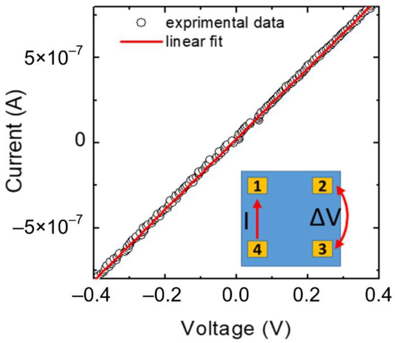
Figure 1. X-ray diffraction patterns of the Cu2O and CuO thin films prepared by MOCVD on the Si substrate at different temperatures from 250 °C (red line), 300 °C (blue line), 350 °C (orange line) to 400 °C (green line).
Materials 15 07790 g001
Figure 2. FE-SEM images of Cu2O and CuO thin films prepared by MOCVD on Si substrate deposited at 250 °C: (a) plan view and (e) cross-section; at 300 °C: (b) plan view and (f) cross-section; at 350 °C: (c) plan view and (g) cross-section; at 400 °C: (d) plan view and (h) cross-section.
Materials 15 07790 g002
Figure 3. Arrhenius plot of the dependence of the logarithm of growth rate vs. 1000/T. Solid line is the linear best fit.
Materials 15 07790 g003
Figure 4. UV-vis absorbance (a) and transmittance (b) spectra of the ITO/quartz substrate (black line); Cu2O on ITO/quartz with thickness of 230 nm (purple line); 140 nm (blue line) and 90 nm (red line).
Materials 15 07790 g004
Figure 5. Tauc’s plot [(αhν)2 against photon energy (hν)] of Cu2O films on ITO_quartz with thickness of 230 nm (purple line); 140 nm (blue line) and 90 nm (red line).
Materials 15 07790 g005
Figure 6. Typical current-voltage (I–V) measurement carried out on a Van der Pauw structure fabricated on Cu2O sample. The inset schematically illustrates the geometry on the sample and the electrical I-V measurement setup.
Materials 15 07790 g006
Figure 7. X-ray diffraction patterns of ITO substrate (black line), Cu2O thin film prepared by MOCVD on the ITO substrate at 250 °C (red line) and the multilayer system MAPI/Cu2O/ITO substrate (brown line). The * indicates the Cu2O peaks. On the left, a cartoon is shown of the planar inverted architecture realized up to the MAPI deposition.
Materials 15 07790 g007
Figure 8. FE-SEM plan view and cross-section images of (a) ITO_quartz substrate; (b) Cu2O thin film deposited at 250 °C on ITO substrate; (c) MAPI film deposited on Cu2O_ITO_quartz substrate. The corresponding 10 μm × 10 μm AFM topographical images (a’c’) are also shown.
Materials 15 07790 g008
Table 1. Summary of the main parameters extracted by Van der Pauw and Hall effect measurements at room temperature.
SampleCarrier TypeResistivity
(Ω cm)
Carrier Concentration
(cm−3)
Mobility
(cm2 V−1 s−1)
230 nmHoles21.5 × 10165.2
140 nmHoles732.0 × 10164.3
90 nmHoles322.8 × 10167.0
Publisher’s Note: MDPI stays neutral with regard to jurisdictional claims in published maps and institutional affiliations.

