Article

The Effects of Graphene Oxide and Reduced Graphene Oxide Conductive Additives on Activated Carbon Supercapacitors

by
Jacob Strimaitis
1,*,
Samuel Adjepong Danquah
1,
Clifford F. Denize
1,
Sangram K. Pradhan
1 and
Messaoud Bahoura
1,2,*
1
Center for Materials Research, Norfolk State University, 700 Park Ave., Norfolk, VA 23504, USA
2
Engineering Department, Norfolk State University, 700 Park Ave., Norfolk, VA 23504, USA
*
Authors to whom correspondence should be addressed.
Processes 2022, 10(11), 2190; https://doi.org/10.3390/pr10112190
Submission received: 20 September 2022 / Revised: 18 October 2022 / Accepted: 20 October 2022 / Published: 26 October 2022

Abstract

:
With their relative ease of production and coupled strong surface functionality and electrical conductivity properties, graphene oxide (GO) and reduced graphene oxide (rGO) are exciting, yet overlooked, graphene-like additive prospects for activated carbon (AC) electrodes in supercapacitors. In this work, we incorporated small amounts of synthesized GO and rGO in AC electrodes via a simple mixing procedure to explore their effects. In addition to materials characterizations, symmetric supercapacitors were made from these electrodes and tested across current densities ranging from 0.1–10 A g−1 and across 10,000 additional charge-discharge cycles at 2 A g−1. Performance measurements indicate that GO and rGO enhance the rate resistance and capacity, respectively, of AC electrodes, but these effects are modest and do not prevent increases in internal resistance over the course of 10,000 cycles. The overall ineffectuality of GO and rGO is reasoned to be due to their isolation and infrequency as a result of the relatively impotent distribution method used.

Graphical Abstract

1. Introduction

The most common materials to select as the electrode of modern supercapacitors are carbon-based [1,2,3]. Specifically, according to Conway, the best carbon-based materials for supercapacitors based on the conventional double-layer type capacitance have (1) high specific surface areas, on the order of 1000 m2 g−1, (2) good intra- and interparticle conductivities in porous matrices, and (3) good electrolyte accessibility to intrapore surface areas [4]. Due to its high specific surface area, commercial availability, and low cost, activated carbon (AC) has received widespread acceptance as the best all-around supercapacitor material [1,5,6]. The capacitance of AC ranges between a strong 40–120 F g−1 in organic electrolytes that nearly doubles in aqueous electrolytes, albeit with a decrease in energy density because of aqueous voltage window limitations [6,7]. However, despite the advantages of AC, it also suffers from a host of problems, including aging effects due to surface redox reactions with organic electrolytes [8], expansion/contraction during cycling [9], the challenging tradeoff between pore size and packing density [10], and poor electrical conductivity [11]. Efforts to improve the performance of porous carbons like AC include optimizing pore size distribution, shape, and structure, increasing surface functionalization, and making composites with additives [5,10,12].
Composites made with AC and other carbon-based additives have received recent attention as promising materials for supercapacitor electrodes [1]. Carbon nanotubes (CNT) [13], carbon nanofibers (CNF) [14], and graphene [15,16] have all been reported as additive contenders. Graphene, particularly because of its uniquely high surface area, chemical stability, and excellent electrical conductivity, has been cited as an exciting new material for the improvement of supercapacitor performance [17]. Unfortunately, pure graphene is notoriously difficult to produce, and synthesis workarounds, which most commonly include the oxygenation, exfoliation, and reduction of graphite, introduce impurities in the graphene lattice that tend to diminish their valued properties [18]. However, these alternative top-down solutions end up being more amenable to large-scale production. Additionally, certain applications of graphene-like products, such as energy storage, may not require pristineness or may in fact benefit from the unique functionalities of overlooked graphene precursors.
Two of the most popular and easily synthesizable top-down graphene-like products for energy storage applications are graphene oxide (GO) and reduced graphene oxide (rGO) [17,19,20]. Between them, rGO has a much higher electrical conductivity [21], whereas GO has a greater proportion of functional groups and hydrophilicity [22]. In the same way that CNF and CNT, when combined and added in small quantities, have complementary structural and conductivity benefits in AC-based supercapacitor electrodes [23], so too could GO and rGO have synergistic benefits when added to AC in a similarly simple mixing procedure. To our knowledge, though, no other groups have investigated the hypothesis that the simplistic incorporation of other graphene-like additives, let alone complementary graphene-like additives, such as GO and rGO, to AC electrodes can likewise enhance AC electrode performance.
In this study, we explore the effects of adding, via a simple mixing process, GO, rGO, and their combination to AC electrodes in symmetric supercapacitors. First, the efficacy of the synthesis technique of GO and rGO is established via X-ray diffraction (XRD) and X-ray photoelectron spectroscopy (XPS) characterization. Then, the morphology of these products, along with standard AC and carbon black (CB), is assessed individually and in combination via field-emission scanning electronic microscopy (FESEM). Finally, the mixtures are fashioned into electrodes, assembled as symmetric supercapacitor cells, and examined electrochemically via a rate performance test across current densities of 0.1–10 A g−1 and a subsequent 10,000 cycles test at 2 A g−1. While overall performances between devices are roughly the same, minor differences emerge between electrodes with GO and rGO with respect to rate resistance and discharge capacity from the rate performance test. Degradation after 10,000 cycles increases the internal resistance of the GO, rGO, and GO+rGO composites with AC, making them less suitable than conventional AC electrodes for long-term use.

2. Experimental

2.1. Chemicals List

The chemicals used in this study were synthetic graphite powder (conducting grade, ~325 mesh, 99.9995%, Alfa Aesar, Heysham, UK), sodium nitrate (NaNO3, ACS reagent, 99.0% min, Alfa Aesar), sulfuric acid (H2SO4, ACS reagent, 95.0–98.0%, Sigma-Aldrich, St. Louis, MO, USA), phosphoric acid (H3PO4, 85.0–88.0 by wt.%, Spectrum, New Brunswick, NJ, USA), potassium permanganate (KMnO4, ACS reagent, 99.0% min, Alfa Aesar), activated carbon (AC, BET surface area 1692 m2 g−1, MTI Corp., Richmond, CA, USA), carboxymethyl cellulose sodium salt (CMC, n~1050, Tokyo Chemical Industry, Tokyo, Japan), Super P conductive carbon black (Super P CB, 99+% metals basis, Alfa Aesar), and deionized water (DI H2O). All chemicals were used as-is unless otherwise stated.

2.2. Graphene Oxide and Reduced Graphene Oxide Synthesis

The GO and rGO additives were synthesized according to a modified Hummers’ method [24]. Briefly, 4 g of pristine graphite (PG) and 2 g of NaNO3 powders were added to a large beaker containing 80 mL of concentrated H2SO4 and 12 mL of H3PO4. The contents of the beaker were continuously stirred at 380 rpm and kept at <20 °C by placing the beaker in an ice bath. Twelve grams of KMnO4 were slowly added, after which the beaker was removed from the ice bath and heated up to 35 °C to begin the reaction. The reaction was quenched after 30 min with the slow addition of 185 mL of DI H2O, followed by an additional 80 mL of warm (~60 °C) DI H2O and <100 mL of 3% H2O2 added dropwise until bubbling ceased. The suspended graphitic oxide particles were washed four times with warm DI H2O via a centrifugation (7200 rpm, 30 min), decantation, and resuspension sequence until the final suspensions had reached a neutral pH. The washed particles were then exfoliated via a sonication (10–15 min), freezing, and air-drying sequence, resulting in a yellowish brown GO powder. Reduced graphene oxide powder was produced by placing GO in a vacuum oven heated to 200 °C for five hours [25].

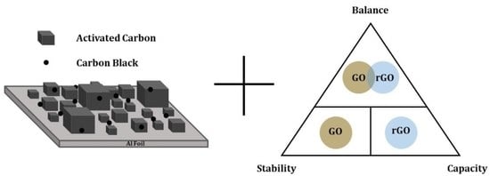
2.3. Electrode Preparation

Active material (AC), carbon additives (Super P CB, GO, and/or rGO), and CMC (dissolved in DI H2O overnight at 12.5 mg mL−1) were combined in an 18:1:1 mass ratio with a total mass of 500 mg per batch. The breakdown of sample compositions is shown in Table 1. Slurries were made by first dry mixing the active material and conductive carbon(s) in an agate mortar and pestle for 5 min. Then, CMC was added and thoroughly mixed until the slurry had a gummy consistency (~30 min). The slurries were deposited as wet films onto separate sheets of battery-grade aluminum foil via a concentric circle painting technique. The electrode films were dried in air before being punched into electrode discs with a diameter of 7/32″. Total dried film mass loadings were between 2.8 and 4.5 mg cm−2 (device mass loadings can be found in Table S1).

2.4. Coin Cell Preparation

Coin cells (type 2032) were assembled as symmetric full cells in an argon-filled glovebox (<0.5 ppm H2O, <0.5 ppm O2). Components were typically arranged as follows: can, electrode, separator (Celgard), electrolyte (<50 μL of 1M LiPF6 in EC/DMC 1:1; Sigma-Aldrich), electrode, stainless steel spacer (15.5 mm diameter × 0.5 mm thickness), wave spring, and cap. Devices were manually crimped for a hermetical seal and then left alone to stabilize for at least 2 h before testing. The open circuit voltage (OCV) of devices before testing was near 0 V. Successful devices could be charged to 2.7 V to power a small LED candle (Figure S1).

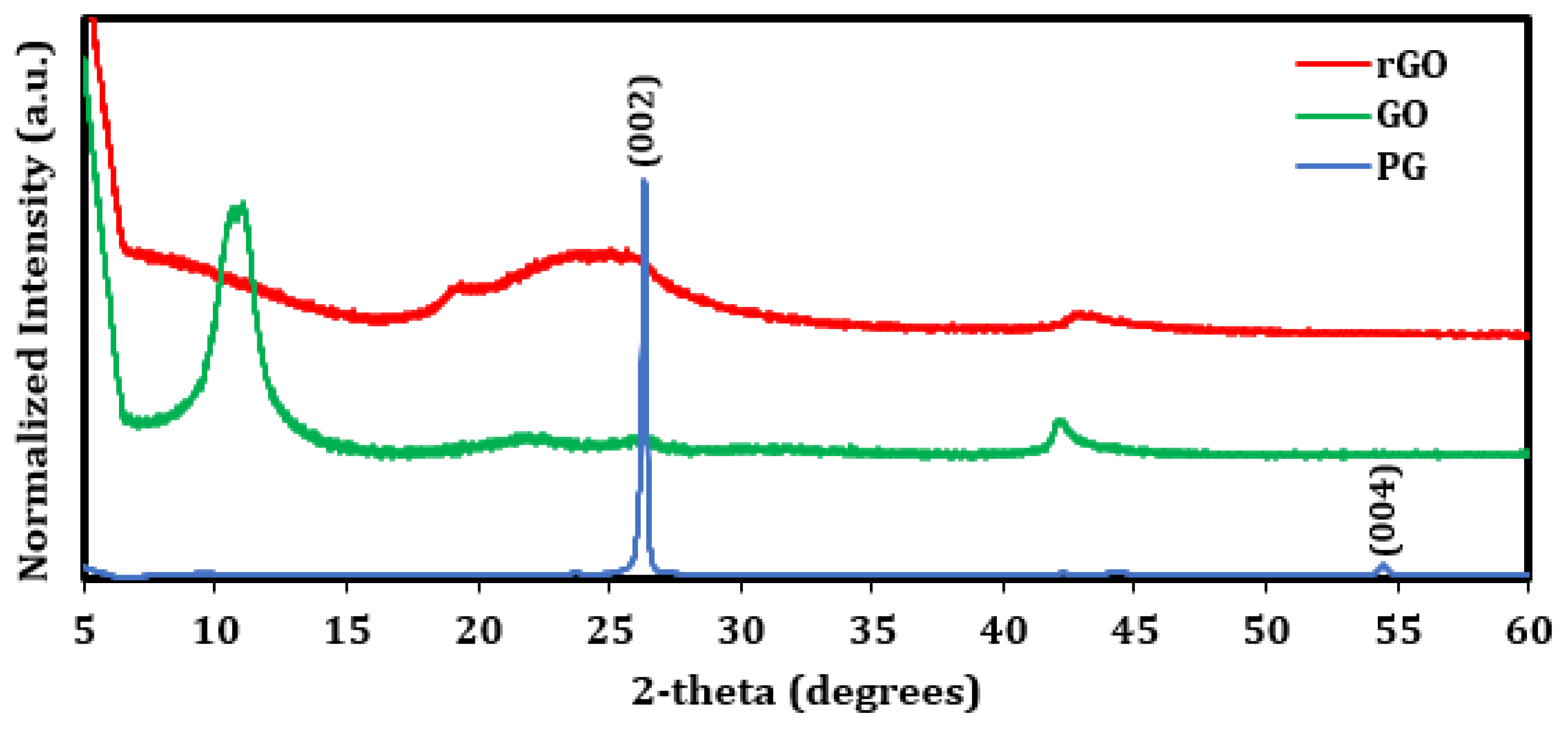
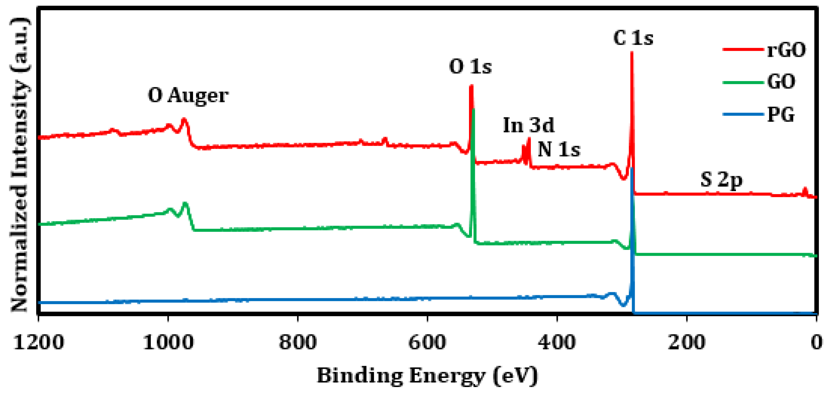
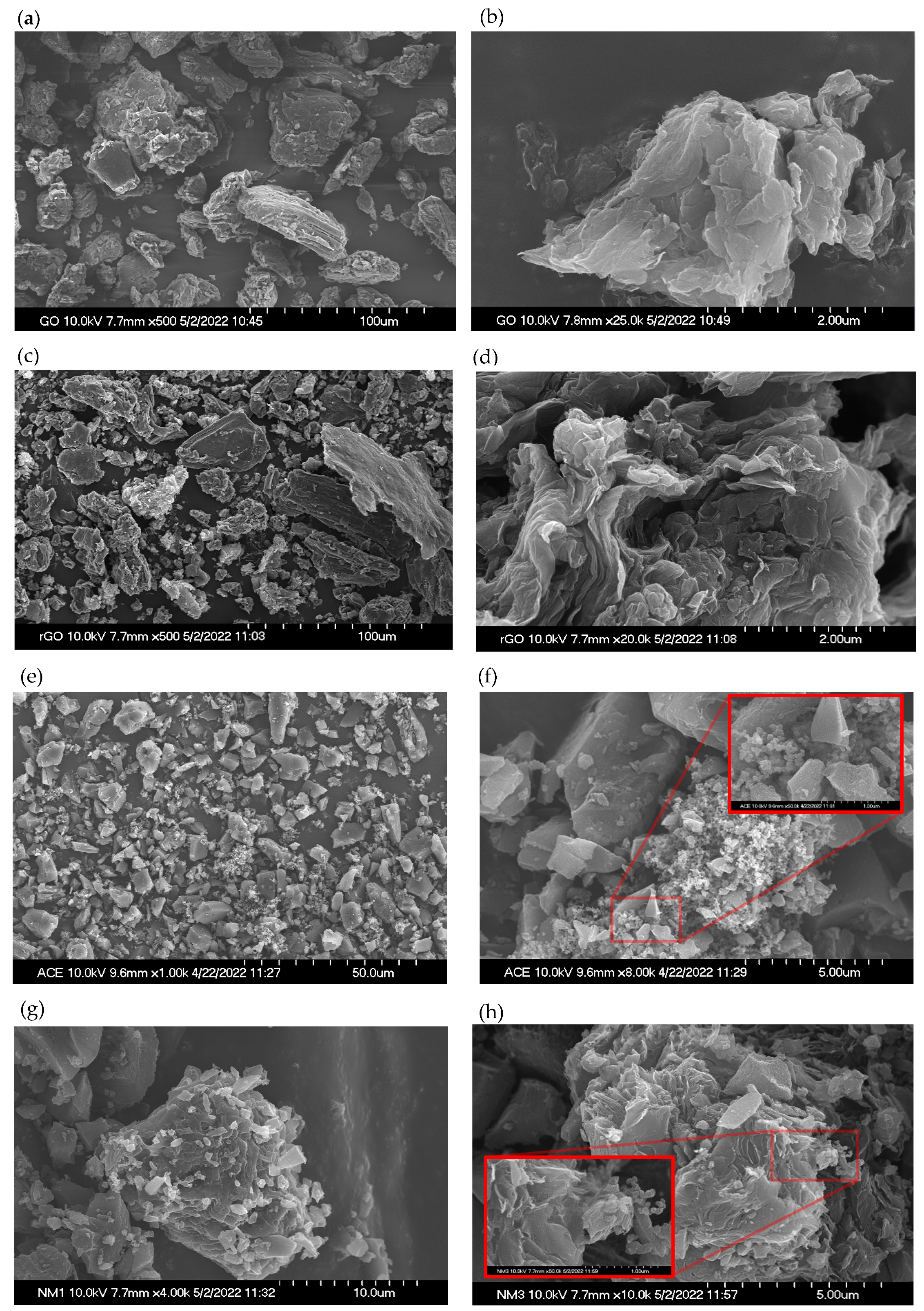
2.5. Material Characterization

The phase and crystal information of powder samples were measured via XRD using a SmartLab X-ray Diffractometer, Rigaku, ran in the Bragg Brentano geometry with a Cu X-ray source. Morphology was observed via FESEM (Hitachi S-4700). Samples were prepared beforehand by sputter coating Au-Pd at 15 mA for 90 s. Composition and electronic states of sample surfaces were measured using XPS (Kratos Axis Ultra DLD, monochromatic Al Kα source). Powder samples were pressed into indium metal, and a charge neutralizer was used to minimize charging effects. Survey and high-resolution scans were acquired at pass energies of 80 eV and 20 eV, respectively. All XPS data were corrected to the C 1s peak at 284.6 eV.

2.6. Electrochemical Characterization

Galvanostatic electrochemical performance was evaluated using an MTI Corp. 8-channel battery analyzer. Coin cells were placed in holders and linked up to the analyzer via alligator clips or inserted directly onto a testing board. All tests were between 0.1–2.7 V (charge up then charge down = 1 cycle; no holding voltage) and proceeded in two sequential phases: rate performance and 10,000-cycle evaluation. For rate performance, cells were charged–discharged between 0.1–10 A g−1. For subsequent 10,000-cycle evaluation, cells were charged-discharged 10,000 times at 2 A g−1. Electrochemical impedance spectroscopy (EIS) and cyclic voltammetry (CV) were acquired using a CH Instruments, Inc. (Austin, TX, USA) Electrochemical Analyzer/Workstation (model CHI660D). EIS was evaluated at OCV between 0.01–100,000 Hz with an amplitude of 10 mV. CV was performed between 0–2.7 V at scan rates of 5, 50, and 500 mV s−1. Specific capacitance of the individual electrodes (Csp, F g−1), energy density of the devices (Ed, Wh kg−1), and power density of the devices (Pd, W kg−1) were calculated according to the following equations [23,26]:
C sp = 4 I t 2 t 1 m V 2 V 1
E d = I m t 1 t 2 V t   d t  
P d = E d t 2 t 1  
where I is the discharge current, m is the total mass of active material (i.e., AC) in the cell, t is the time (t1 is time at beginning of discharge, t2 is time end of discharge), and V is cell voltage (V1 is voltage at beginning of discharge, V2 is voltage at end of discharge).

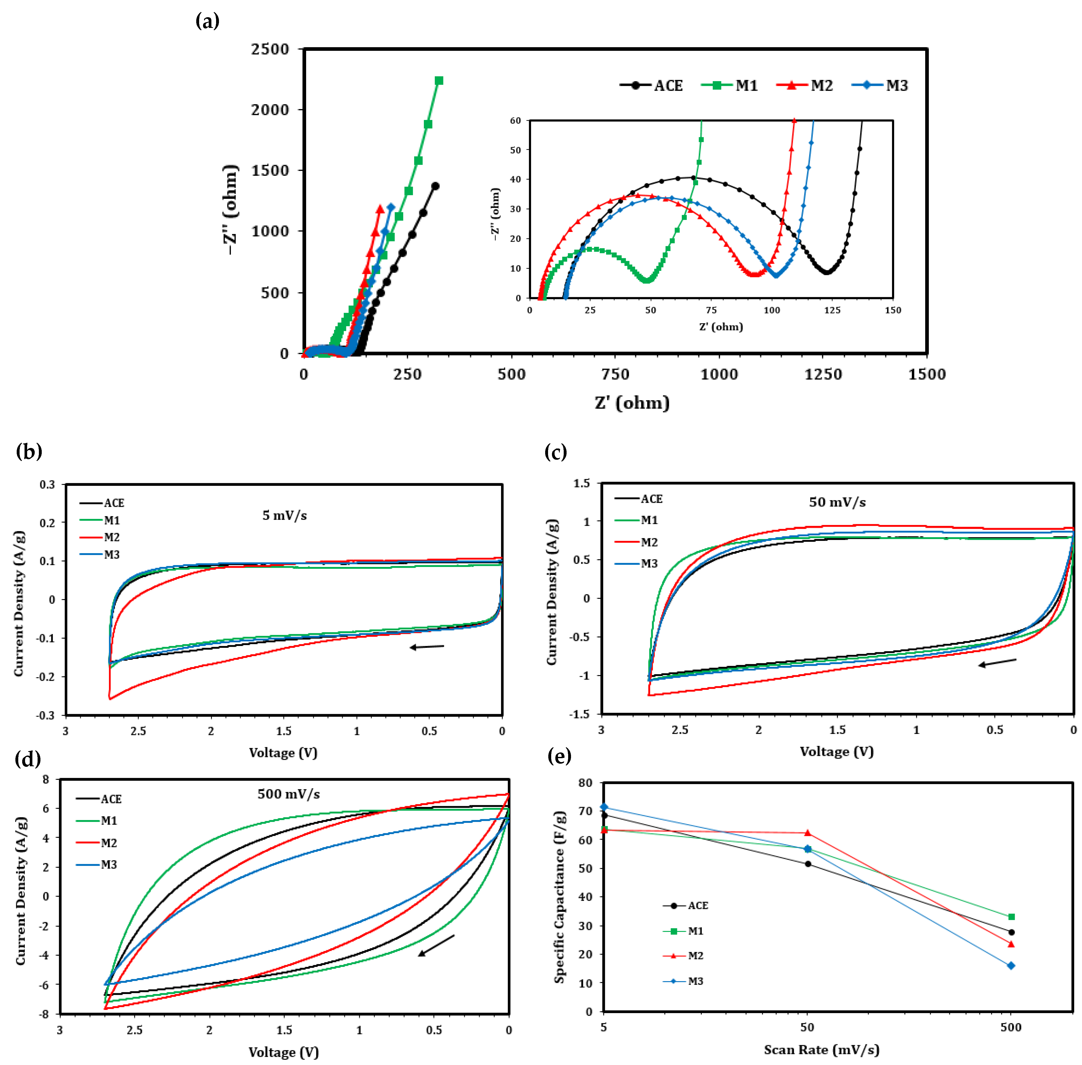
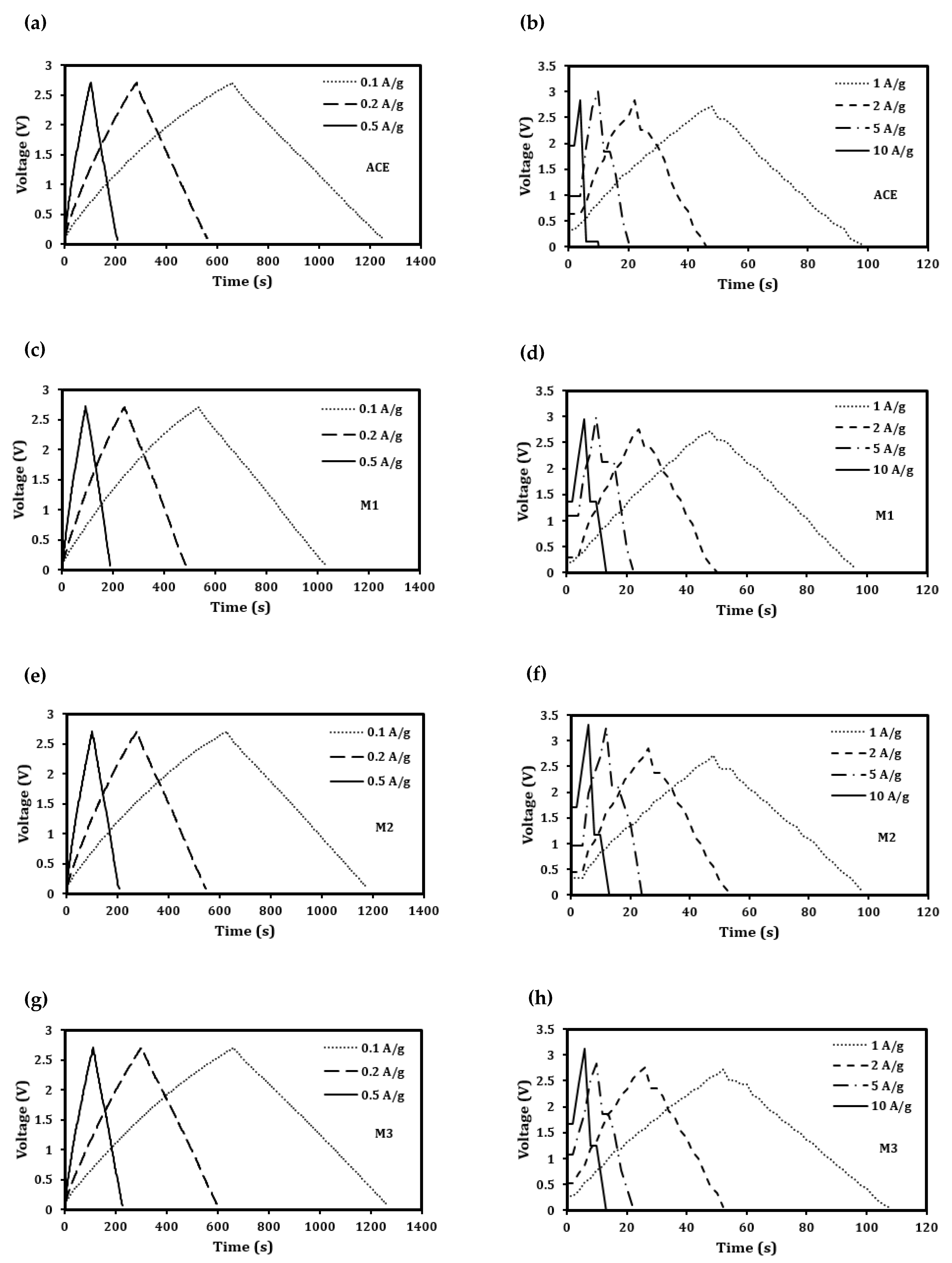
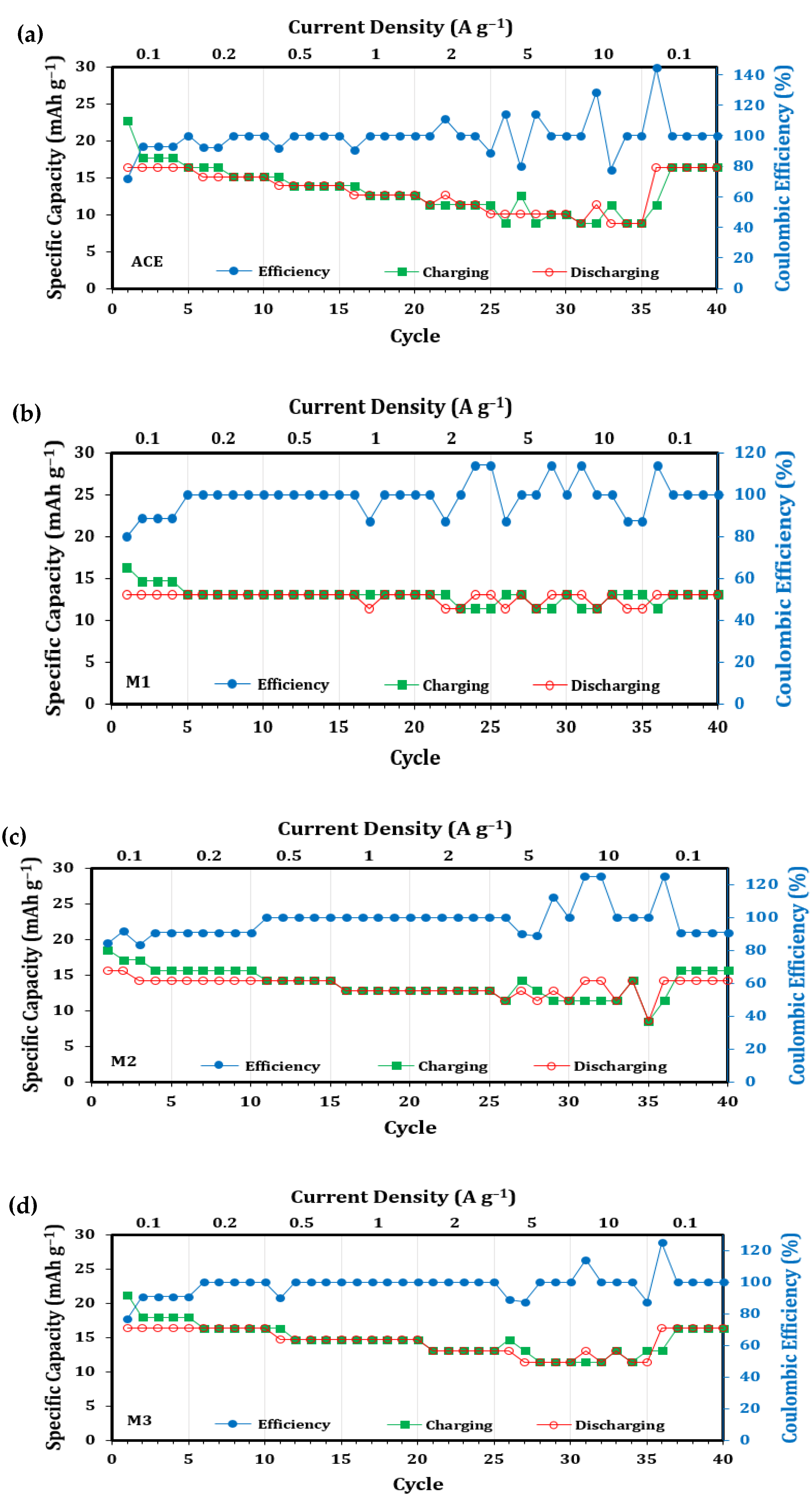
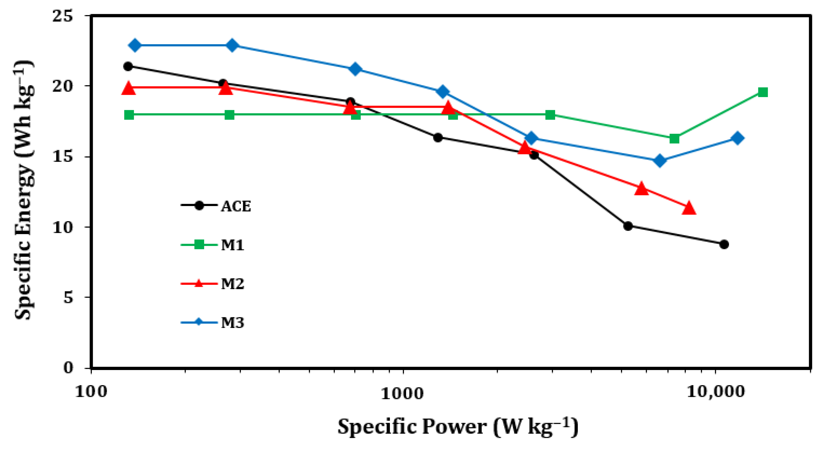
3. Results & Discussion

XRD was used to assess the crystallinity of PG, GO, and rGO (Figure 1). The spectrum for PG contains a sharp and strong peak at 2θ = 26.34 and a weak peak at 2θ = 54.44 that match the peaks associated with the (002) and (004) Miller indices, respectively, of reference Graphite-2H (PDF Card No.: 00-041-1487), supporting the pristine quality of the source graphite used in this study. The spectrum for GO contains one broad and strong peak at 2θ = 10.8 and one weak peak at 2θ = 42.7. The spectrum for rGO differs from that of GO insofar as it contains no discernable peaks near 2θ = 10 and one very broad peak at 2θ = 24, although it has a similarly weak peak at 2θ = 43.1. There is variability in the literature regarding the location and interpretation of the discernable GO and rGO peaks [21,27,28,29], but in general, there exists a broad and strong peak between 2θ = 9–12 for GO, a broader peak near 2θ = 25 for rGO, and a weak peak between 2θ = 40–45 for both GO and rGO, all of which are found in our samples. These observations are consistent with reference database searches as well, where it was found that GO matches the (001) plane of the peak at 2θ = 9.70 of graphene oxide (PDF Card No.: 00-065-1528). Similarly, rGO matches the (002) plane of the peak at 2θ = 25.92 and the (100) plane of the peak at 2θ = 42.96 of carbon nanotubes (PDF Card No.: 00-058-1638), which is a low-oxygen allotrope of graphene.
XPS was used to assess the chemical compositions of PG, GO, and rGO. Survey scans reveal the presence of carbon at a calibrated binding energy of 284.6 eV in all three samples and a significant presence of oxygen at a binding energy near 533 eV in GO and rGO (Figure 2). In addition to traces of In substrate, GO and rGO contain trace amounts (<1% by atomic concentration) of N and S at binding energies of 400 eV and 167 eV, respectively, and rGO contains trace amounts (0.6% by atomic concentration) of Si at a binding energy of 101 eV, all of which are likely the result of minor unremoved impurities (e.g., from sodium nitrate and sulfuric acid) or contaminations during synthesis. High-resolution scans of C 1s and O 1s can be found in Figure S2. Graphite expectedly contains the highest C/O ratio at 199 by atomic concentration percent (Table 2). The C/O ratio of GO is significantly lower at 2.19 by atomic concentration percent, indicating a successful oxygenation of graphite that imbues strong surface functionality, and the C/O ratio of rGO is higher at 4.65 by atomic concentration percent, indicating a successful, albeit partial, reduction of oxygen of GO via heating. Similar observations comparing GO and rGO have been reported by others [30,31], further confirming the efficacy of the GO and rGO syntheses in this study.
FESEM was used to assess the morphological characteristics of the individual components of the electrodes and their composite structures. Agglomerated GO particles range in diameter from 5–100 μm (Figure 3a) and have a disordered layered appearance (Figure 3b). Reduced graphene oxide particles are likewise between 5–100 μm in diameter and have disordered stacking (Figure 3c), though their degree of wrinkledness is somewhat higher than GO particles (Figure 3d). The AC in ACE is box- or shard-like and smaller in size than GO and rGO, with particles as large as 20 μm and as small as ~200 nm (Figure 3e). Super P CB is randomly distributed across AC as spongelike aggregates up to 5 μm in diameter. These aggregates are composed of networks of carbon spheres that are 20–100 nm in size (Figure 3f). When GO is introduced into the electrode mixture, small AC particles (~1 μm diameter) cling to GO’s surface (Figure 3g). Micron-sized AC particles also cling to the surface of rGO particles (Figure 3h), along with CB (Figure 3h inset), although to a smaller degree. Taken together, GO and rGO particles do not unstack themselves when interacting with AC and CB, nor do they de-aggregate CB or bridge connections between AC particles. Instead, GO and rGO appear to act as large, infrequent, and mostly isolated magnets that sequester small amounts of micron-sized AC particles and CB aggregates via surface attachment.
Device EIS and CV characteristics are given in Figure 4. Consistent with supercapacitor Nyquist plots [23], all devices in this study have a semicircular shape in the high-to-medium frequency region that rises near vertically in the mid-to-low frequency region (Figure 4a). The lack of a distinguishable 45° Warburg element in the mid frequency region and the overall high impedance values suggest that the electrochemical kinetics in the devices are sluggish [26], an observation that could be attributable to the type of organic electrolyte used in this study. The equivalent series resistance, which is determined from the x-axis intercept in the high frequency region, is lower for devices with electrodes containing GO (i.e., 5.7 Ω and 4.4 Ω for M1 and M2, respectively) than it is for devices with electrodes not containing GO (i.e., 14.4 Ω and 15.0 Ω for ACE and M3, respectively). This difference indicates that the total internal resistance of the cell, including electrolyte and electrodes, is reduced in the presence of GO. The charge transfer resistance, which, in supercapacitors, is more likely a reflection of the interfacial impedance between the current collector and electrode, is determined from the diameter of the semicircle [32]. It is smallest for M1 (46.3 Ω), nearly identical for M2 and M3 (90.6 Ω and 91 Ω, respectively), and highest for ACE (112.6 Ω), indicating that the presence of GO and rGO enhances electrical conductivity between activated carbon and the aluminum foil current collector, though this enhancement is strongest with GO alone. The CV curves have near-rectangular shapes at the lowest scan rate (Figure 4b), which is expected for electrochemical double layer capacitance (EDLC) devices, such as supercapacitors [23,26]. At higher scan rates (Figure 4c,d), the rectangular shapes become enlarged to ovals, an effect that is most pronounced in M3 and least pronounced in M1 and is associated with the relative loss and sustainment, respectively, of capacitance in those devices. Figure 4e shows the quantification of capacitance calculated from average cathodic currents at each scan rate. As expected with the loss of shape in the CV curves, the devices experienced a loss in capacitance from 60–75 F g−1 at 5 mV s−1 to 15–40 F g−1 500 mV s−1, although these results are consistent with what would be expected from supercapacitor electrodes in an organic electrolyte [6,23]. M1 had the strongest capacitance stability between the scan rates of 5 and 500 mV s−1, a result that may be attributable to its enhanced interfacial charge transfer conductivity.
Cells underwent rate performance tests to evaluate their ability to withstand multiple charging–discharging cycles under current densities ranging from 0.1 to 10 A g−1. As expected with supercapacitors, the voltage-time representations of these tests reveal linear, near triangular charge–discharge profiles at lower currents below 1 A g−1 (Figure 5a,c,e,g). The calculated average capacitances for ACE, M1, M2, and M3 at 0.1 A g−1 are 91.6 F g−1, 72.8 F g−1, 82.8 F g−1, and 91.2 F g−1, respectively, further indicating that the materials are performing as expected in an organic electrolyte [6,23]. The voltage–time curves are similarly linear at higher currents between 1–10 A g−1 (Figure 5b,d,f,h), although there are noticeable differences in voltage limit and smoothness of curve shape as a result of measurement limitations in the battery analyzer. Internal resistance, as measured by the magnitude of the near-vertical voltage or iR drop in the first moments of discharge [26], also increases as current density increases, which is expected with supercapacitors [23].
Performances of the devices in terms of capacity and Coulombic efficiency are given in Figure 6. Discharge capacities follow similar trends across all devices, ranging from 8.8 to 16.4 mAh g−1 and decreasing as current densities increase. Rate resistance is strongest in M1, insofar as it only experienced a 7.6% decrease in discharge capacity from 13.1 mAh g−1 to 12.1 mAh g−1 between its average first lowest current density (0.1 A g−1) and highest current density (10 A g−1) discharge capacities. In order of increasing percent decrease, M2 experienced the next highest rate resistance at a 15.5% decrease in capacity from 14.8 mAh g−1 to 12.5 mAh g−1, followed by M3 at a 25.8% capacity decrease from 16.3 mAh g−1 to 12.1 mAh g−1 and then ACE at a 43.3% decrease from 16.4 mAh g−1 to 9.3 mAh g−1. Rate resiliency, as measured by the percentage change in average discharge capacity between cycles 36–40 and 1–5, is equally tied among ACE, M1, and M3 at 0% average change, whereas capacity only drops for M2 by 4.1%.
When compared on a Ragone plot (Figure 7), all four devices have mostly overlapping energy and power densities and can maintain at least 5 Wh kg−1 between 0.1 and 10,000 W kg−1. While the energy density of supercapacitors can reach as high as 100 Wh kg−1 [15], it is more common to find their energy densities between 5–25 Wh kg−1 and their power densities between 100–10,000 W kg−1 [16,23], ranges which we see in our results as well. Inconsistencies in Figure 7 mainly appear beyond 2000 W kg−1, where battery analyzer measurement limitations associated with higher currents have their strongest effect. Taken together, these rate performance data suggest that adding GO and rGO to ACE have marginal impacts on its overall discharge capacity capability, rate resiliency, energy density, and power density, although based on the rate resistance analysis, GO may introduce a resistance reduction effect in the short term that keeps ACE from losing capacity at high currents. Likewise, by virtue of its greater electrical conductivity, rGO enhances the magnitude of discharge capacity and energy density compared to ACE, but this effect is slight.
Cells were also tested for an additional 10,000 charge-discharge cycles at 2 A g−1 (Figure 8). Across measures of capacity retention, stability, and internal resistance, ACE outperformed all mixtures. After 10,000 cycles, ACE had dropped from an initial discharge capacity of 12.6 mAh g−1 to 10.1 mAh g−1 (80% of initial capacity), whereas M1 dropped from 11.4 mAh g−1 to 8.2 mAh g−1 (71% of initial capacity), M2 dropped from 12.8 mAh g−1 to 9.9 mAh g−1 (78% of initial capacity), and M3 dropped from 14.7 mAh g−1 to 11.4 mAh g−1 (78% of initial capacity). Because of the near-horizontal slopes of the long-term cycling curves (R2 << 0.99 with linear trendline fit; Table 3), the stability of the devices was evaluated using statistical measures of central tendency and spread. While only having a moderate average discharge capacity of 10.8 mAh g−1, ACE had the most stable profile with a standard deviation of 0.77 mAh g−1. In order of decreasing stability, M3 was the most stable of the alternative mixtures, with an average discharge capacity of 12.3 mAh g−1 and a standard deviation of 0.95 mAh g−1, followed by M1 with an average discharge capacity of 10.6 mAh g−1 and a standard deviation of 1.05 mAh g−1 and then M2 with an average discharge capacity of 10.6 mAh g−1 and a standard deviation of 1.37 mAh g−1. After 10,000 charge-discharge cycles, ACE experienced the least increase of internal resistance insofar as it experienced an iR drop of 0.4 V to 0.51 V (a 27.5% increase), followed by M3 from 0.39 V to 0.62 V (59% increase), M1 from 0.33 V to 0.96 V (191% increase), and M2 from 0.4 V to 1.23 V (207.5% increase). These data suggest that, despite initial capacity improvements with the addition of GO and especially rGO, these additives cause marked reductions in stability and increases in internal resistance after 10,000 cycles.
The reason for the absence of significant electrochemical performance enhancements of the GO/rGO additive electrodes compared to ACE is likely due, at least in part, to the isolated nature of the large GO/rGO particles themselves. Others have demonstrated significant performance increases to AC + CB electrodes with the addition of CNT and CNF [23], both of which are sub-micron in size and so able to ubiquitously populate, and thereby better affect the capabilities of, the AC + CB network. Far from entwining the randomly distributed AC and CB clumps, GO and rGO particles are too large and too few to be effective.

4. Conclusions

Incorporating small amounts of GO and rGO powder in ACE supercapacitors only modestly affects their overall electrochemical performance. Graphene oxide may be able to increase rate stability, as evidenced by its generally flat capacity profile across the rate performance test compared to the other devices, but its dramatic increase in internal resistance, its low discharge capacity retention, and its instability over the 10,000 cycles test indicates that it experiences some degree of structural breakdown in these charges–discharges that renders it unreliable for the long term. Adding rGO, alternatively, improves energy density and cycling capacity compared to ACE, an effect that can be ascribed to the reported strong electrical conductivity of rGO, but rGO nonetheless instills internal resistance that drops the long-term capacity and stability of devices to a greater degree than ACE alone. A combination of GO and rGO reveals a tradeoff between the short-term rate stability and overall magnitude of discharge capacity associated with its respective components, but even this combination suffers from similar long-term instability and significant increases in internal resistance. Of the four options, ACE is the most balanced electrochemically and remains the simplest choice for supercapacitors. Efforts to improve ACE performance by incorporating GO and especially rGO additives may still prove fruitful if, for instance, the individual GO/rGO layers could be disentangled and disbursed across the AC + CB network. However, such enhancements must necessarily come from preparation procedures more complex than the straightforward mixing method explored in this study.

Supplementary Materials

The following supporting information can be downloaded at: https://www.mdpi.com/article/10.3390/pr10112190/s1, Table S1: Mass loadings for ACE, M1, M2, and M3.; Figure S1: Images of unlit (a) and lit (b–e) LED candle powered by charged (2.7 V) ACE (b), M1 (c), M2 (d), and M3 (e) devices.; Figure S2: High-resolution XPS O 1s (a) and C 1s (b) spectra of pristine graphite (PG), graphene oxide (GO), and reduced graphene oxide (rGO). Spectra have been offset for clarity.

Author Contributions

Conceptualization, J.S.; methodology, J.S.; software, J.S.; validation, S.A.D. and C.F.D.; formal analysis, J.S.; investigation, J.S.; resources, S.K.P. and M.B.; data curation, J.S.; writing—original draft preparation, J.S.; writing—review and editing, J.S., S.A.D., C.F.D., S.K.P. and M.B.; visualization, J.S.; supervision, M.B.; project administration, M.B.; funding acquisition, M.B. All authors have read and agreed to the published version of the manuscript.

Funding

This work is supported by the National Science Foundation (NSF) grant nos. HRD 1547771 and HRD 1036494. Part of this work was performed at the Chapel Hill Analytical and Nanofabrication Laboratory, CHANL, a member of the North Carolina Research Triangle Nanotechnology Network, RTNN, which is supported by the National Science Foundation, Grant ECCS-2025064, as part of the National Nanotechnology Coordinated Infrastructure, NNCI.

Data Availability Statement

Not applicable.

Acknowledgments

We would like to thank Carrie Donley and Josh Chen at the University of North Carolina at Chapel Hill for XRD and XPS materials characterization and in-depth analysis. We would also like to thank Olga Trofimova and the rest of the Applied Research Center Core Labs team at the College of William and Mary in Virginia for FESEM materials characterization.

Conflicts of Interest

The authors declare no conflict of interest.

References

  1. Dubey, R.; Guruviah, V. Review of carbon-based electrode materials for supercapacitor energy storage. Ionics 2019, 25, 1419–1445. [Google Scholar] [CrossRef]
  2. Wang, Y.; Zhang, L.; Hou, H.; Xu, W.; Duan, G.; He, S.; Liu, K.; Jiang, S. Recent progress in carbon-based materials for supercapacitor electrodes: A review. J. Mater. Sci. 2021, 56, 173–200. [Google Scholar] [CrossRef]
  3. Wang, G.; Zhang, L.; Zhang, J. A review of electrode materials for electrochemical supercapacitors. Chem. Soc. Rev. 2012, 41, 797–828. [Google Scholar] [CrossRef] [PubMed] [Green Version]
  4. Conway, B.E. Electrochemical Supercapacitors: Scientific Fundamentals and Technological Applications; Kluwer Academic/Plenum Publishers: New York, NY, USA, 1999. [Google Scholar]
  5. Borenstein, A.; Hanna, O.; Attias, R.; Luski, S.; Brousse, T.; Aurbach, D. Carbon-Based composite materials for supercapacitor electrodes: A review. J. Mater. Chem. A 2017, 5, 12653–12672. [Google Scholar] [CrossRef]
  6. Frackowiak, E. Carbon materials for supercapacitor application. Phys. Chem. Chem. Phys. 2007, 9, 1774–1785. [Google Scholar] [CrossRef]
  7. Burke, A. Ultracapacitors: Why, how, and where is the technology. J. Power Sources 2000, 91, 37–50. [Google Scholar] [CrossRef] [Green Version]
  8. Azaïs, P.; Duclaux, L.; Florian, P.; Massiot, D.; Lillo-Rodenas, M.-A.; Linares-Solano, A.; Peres, J.-P.; Jehoulet, C.; Béguin, F. Causes of supercapacitors ageing in organic electrolyte. J. Power Sources 2007, 171, 1046–1053. [Google Scholar] [CrossRef]
  9. Hahn, M.; Barbieri, O.; Gallay, R.; Kötz, R. A dilatometric study of the voltage limitation of carbonaceous electrodes in aprotic EDLC type electrolytes by charge-induced strain. Carbon 2006, 44, 2523–2533. [Google Scholar] [CrossRef]
  10. Zhang, L.L.; Zhao, X.S. Carbon-Based materials as supercapacitor electrodes. Chem. Soc. Rev. 2009, 38, 2520–2531. [Google Scholar] [CrossRef]
  11. Huang, Y.; Zhao, Y.; Gong, Q.; Weng, M.; Bai, J.; Liu, X.; Jiang, Y.; Wang, J.; Wang, D.; Shao, Y.; et al. Experimental and Correlative Analyses of the Ageing Mechanism of Activated Carbon Based Supercapacitor. Electrochim. Acta 2017, 228, 214–225. [Google Scholar] [CrossRef]
  12. Wang, Y.; Song, Y.; Xia, Y. Electrochemical capacitors: Mechanism, materials, systems, characterization and applications. Chem. Soc. Rev. 2016, 45, 5925–5950. [Google Scholar] [CrossRef]
  13. Lu, W.; Hartman, R.; Qu, L.; Dai, L. Nanocomposite Electrodes for High-Performance Supercapacitors. J. Phys. Chem. Lett. 2011, 2, 655–660. [Google Scholar] [CrossRef]
  14. Li, Q.; Liu, F.; Zhang, L.; Nelson, B.; Zhang, S.; Ma, C.; Tao, X.; Cheng, J.; Zhang, X. In situ construction of potato starch based carbon nanofiber/activated carbon hybrid structure for high-performance electrical double layer capacitor. J. Power Sources 2012, 207, 199–204. [Google Scholar] [CrossRef]
  15. Chen, Y.; Zhang, X.; Zhang, H.; Sun, X.; Zhang, D.; Ma, Y. High-Performance supercapacitors based on a graphene–activated carbon composite prepared by chemical activation. RSC Adv. 2012, 2, 7747–7753. [Google Scholar] [CrossRef]
  16. Zheng, C.; Zhou, X.; Cao, H.; Wang, G.; Liu, Z. Synthesis of porous graphene/activated carbon composite with high packing density and large specific surface area for supercapacitor electrode material. J. Power Sources 2014, 258, 290–296. [Google Scholar] [CrossRef]
  17. Zhu, J.; Yang, D.; Yin, Z.; Yan, Q.; Zhang, H. Graphene and Graphene-Based Materials for Energy Storage Applications. Small 2014, 10, 3480–3498. [Google Scholar] [CrossRef]
  18. Zhu, Y.; Murali, S.; Cai, W.; Li, X.; Suk, J.W.; Potts, J.R.; Ruoff, R.S. Graphene and graphene oxide: Synthesis, properties, and applications. Adv. Mater. 2010, 22, 3906–3924. [Google Scholar] [CrossRef]
  19. Shulga, Y.M.; Shulga, N.Y.; Parkhomenko, Y.N. Carbon nanostructures reduced from graphite oxide as electrode materials for supercapacitors. Mod. Electron. Mater. 2015, 1, 1–9. [Google Scholar] [CrossRef]
  20. Kumar, H.; Sharma, R.; Yadav, A.; Kumari, R. Recent advancement made in the field of reduced graphene oxide-based nanocomposites used in the energy storage devices: A review. J. Energy Storage 2020, 33, 102032. [Google Scholar] [CrossRef]
  21. Mokhtar, M.M.; Abo El Enein, S.A.; Hassaan, M.Y.; Morsy, M.S.; Khalil, M.H. Thermally Reduced Graphene Oxide: Synthesis, Structural and Electrical Properties. Int. J. Nanoparticles Nanotechnol. 2017, 3, 1–9. [Google Scholar]
  22. Yu, W.; Sisi, L.; Haiyan, Y.; Jie, L. Progress in the functional modification of graphene/graphene oxide: A review. RSC Adv. 2020, 10, 15328–15345. [Google Scholar] [CrossRef]
  23. Cheng, F.; Yang, X.; Zhang, S.; Lu, W. Boosting the supercapacitor performances of activated carbon with carbon nanomaterials. J. Power Sources 2020, 450, 227678. [Google Scholar] [CrossRef]
  24. Pradhan, S.K.; Xiao, B.; Mishra, S.; Killam, A.; Pradhan, A.K. Resistive switching behavior of reduced graphene oxide memory cells for low power nonvolatile device application. Sci. Rep. 2016, 6, 26763. [Google Scholar] [CrossRef] [PubMed]
  25. Kaniyoor, A.; Baby, T.T.; Arockiadoss, T.; Rajalakshmi, N.; Ramaprabhu, S. Wrinkled Graphenes: A Study on the Effects of Synthesis Parameters on Exfoliation-Reduction of Graphite Oxide. J. Phys. Chem. C 2011, 115, 17660–17669. [Google Scholar] [CrossRef]
  26. Noori, A.; El-Kady, M.F.; Rahmanifar, M.S.; Kaner, R.B.; Mousavi, M.F. Towards establishing standard performance metrics for batteries, supercapacitors and beyond. Chem. Soc. Rev. 2019, 48, 1272–1341. [Google Scholar] [CrossRef] [PubMed]
  27. Stobinski, L.; Lesiak, B.; Malolepszy, A.; Mazurkiewicz, M.; Mierzwa, B.; Zemek, J.; Jiricek, P.; Bieloshapka, I. Graphene oxide and reduced graphene oxide studied by the XRD, TEM and electron spectroscopy methods. J. Electron Spectrosc. Relat. Phenom. 2014, 195, 145–154. [Google Scholar] [CrossRef]
  28. Cao, N.; Zhang, Y. Study of Reduced Graphene Oxide Preparation by Hummers’ Method and Related Characterization. J. Nanomater. 2015, 2015, 1–5. [Google Scholar] [CrossRef] [Green Version]
  29. Alam, S.N.; Sharma, N.; Kumar, L. Synthesis of Graphene Oxide (GO) by Modified Hummers Method and Its Thermal Reduction to Obtain Reduced Graphene Oxide (rGO)*. Graphene 2017, 6, 1–18. [Google Scholar] [CrossRef] [Green Version]
  30. Al-Gaashani, R.; Najjar, A.; Zakaria, Y.; Mansour, S.; Atieh, M.A. XPS and structural studies of high quality graphene oxide and reduced graphene oxide prepared by different chemical oxidation methods. Ceram. Int. 2019, 45, 14439–14448. [Google Scholar] [CrossRef]
  31. Botas, C.; Álvarez, P.; Blanco, C.; Santamaria, R.; Granda, M.; Gutiérrez, M.D.; Rodriguez-Reinoso, F.; Menéndez, R. Critical temperatures in the synthesis of graphene-like materials by thermal exfoliation–reduction of graphite oxide. Carbon 2013, 52, 476–485. [Google Scholar] [CrossRef] [Green Version]
  32. Mathis, T.S.; Kurra, N.; Wang, X.; Pinto, D.; Simon, P.; Gogotsi, Y. Energy Storage Data Reporting in Perspective—Guidelines for Interpreting the Performance of Electrochemical Energy Storage Systems. Adv. Energy Mater. 2019, 9, 1902007. [Google Scholar] [CrossRef]
Figure 1. XRD patterns of pristine graphite (PG), synthesized graphene oxide (GO), and synthesized reduced graphene oxide (rGO). Spectra have been offset for clarity.
Processes 10 02190 g001
Figure 2. XPS survey spectra of pristine graphite (PG), synthesized graphene oxide (GO), and synthesized reduced graphene oxide (rGO). Spectra have been offset for clarity.
Processes 10 02190 g002
Figure 3. FESEM images of electrode components and their combinations: low (a) and high (b) magnifications of GO; low (c) and high (d) magnifications of rGO; low (e), high (f), and highest (inset) magnifications of ACE; high (g) magnification of GO particle in M1 mixture; high (h) and highest (inset) magnifications of rGO in M3 mixture.
Processes 10 02190 g003
Figure 4. Nyquist plot (a) with zoomed high-to-mid frequency data (inset); cyclic voltammetry curves obtained at 5 mV s−1 (b), 50 mV s−1 (c), and 500 mV s−1 (d), and average cathodic current-specific capacitances (e) of ACE, M1, M2, and M3. Arrows indicate beginning and sweep direction of cyclic voltammetry.
Processes 10 02190 g004
Figure 5. Representative voltage–time curves for rate performance test split between 0.1–0.5 A g−1 (a,c,e,g) and 1–10 A g−1 (b,d,f,h). Subfigures (a,b) correspond to ACE, (c,d) correspond to M1, (e,f) correspond to M2, and (g,h) correspond to M3.
Processes 10 02190 g005
Figure 6. Rate performance test-specific capacities and Coulombic efficiencies for ACE (a), M1 (b), M2 (c), and M3 (d).
Processes 10 02190 g006
Figure 7. Gravimetric Ragone plot comparing ACE, M1, M2, and M3.
Processes 10 02190 g007
Figure 8. Long-term cyclic stability performance (a) and voltage–time curves of cycles 1, 5k, and 10k (b) of ACE, M1, M2, and M3.
Processes 10 02190 g008
Table 1. Comparison of electrode configurations.
DescriptionLabelComposition (wt.%)
Conventional AC electrodeACEAC/Super P (90/5)
GO addedM1AC/Super P/GO (90/2.5/2.5)
GO and rGO added (1:1)M2AC/Super P/GO/rGO (90/2.5/1.25/1.25)
rGO addedM3AC/Super P/rGO (90/2.5/2.5)
Table 2. XPS compositional analysis and quantitative peak fittings of C 1s and O 1s scans.
SamplePeakBinding Energy (eV)Atomic Conc. (%)C/O Ratio
Pristine graphite (PG)C 1s284.6199.5199
O 1s533.510.5
Graphene oxide (GO)C 1s C-C/C=C284.5927.52.19
C 1s C-O286.6135.1
C 1s C=O288.375.4
O 1s532.3531.0
Reduced graphene oxide (rGO)C 1s C-C/C=C284.9156.34.65
C 1s C-O286.339.7
C 1s C=O288.1811.7
C 1s O-C=O291.052.8
O 1s531.59, 53317.3
Table 3. Output linear trend line values for 10,000 cycles test.
LabelSlope (10−5)Y-InterceptR2
ACE−4.2810.980.027
M1−29.412.040.688
M2−40.812.600.782
M3−23.113.420.526
Publisher’s Note: MDPI stays neutral with regard to jurisdictional claims in published maps and institutional affiliations.

