1. Introduction
Close-distance coal seam groups are widely distributed in China [
1,
2]. Limited by technical and coal seam reserve conditions, wide coal pillars are often reserved when mining the overlying coal seam to maintain the stope mining roadway [
3,
4]. The many remaining coal pillars after the stope mining of the coal seam alter the stress environment of their floor, causing stress elevations dominated by vertical stresses in the floor rock near the remaining coal pillars [
5,
6]. Under such high stresses, the surrounding rock of the stope mining roadways in the underlying coal seam inevitably develops cracks [
7,
8]. In the meantime, the superposition of lateral support pressure stresses during the mining at the working face of the underlying coal seam further aggravates the stope-mining roadway deformation and failure, which seriously affects the safe production of the mine [
9,
10,
11,
12,
13]. Therefore, studies on the failure mechanism and stability control techniques of roadways under multiple disturbances in close-distance coal seams are urgently needed.
To clarify the effects of remaining coal pillars on the mine pressure behaviors of stope mining roadways in the underlying coal seam, scholars worldwide conducted extensive research based on methods such as mining theory analysis, numerical simulation, and field applications. Research by Zhang et al. [
14] concluded that subjected to high vertical stress, part of the roadway under the remaining coal pillar developed large deformations and became difficult to maintain, and the stress concentration and surrounding rock deformation on the side of coal pillars could be effectively reduced by the reasonable roadway layout. Fang et al. [
15] demonstrated that roadways were easily destabilized under the effect of mining if the remaining coal pillars were narrow in the gob of the overlying coal seam or if the roadway of the underlying coal seam was directly below while the roadway-supporting coal pillars near the working face of the current coal seam were small. Numerical simulations have been conducted to analyze the stress transfer of the coal pillar floor in the overlying coal seam [
16,
17]. To address the challenge of gob-side roadway stability control in close-distance coal seams, Zhang et al. [
18] determined the design parameters of the roadway-side filling body based on the structural mechanics model of the gob-side entry retaining surrounding rocks and proposed a support technology combining high-strength anchor rods, anchor cables, and steel beams. Jiang et al. [
19] analyzed the coal pillar-induced impact patterns in deep close distance coal seams and medium mining depth far distance coal seams. Through comprehensive research, Liu et al. [
20] analyzed the destabilization and failure processes of roadways in the gob of close-distance coal seams and proposed a joint active-passive control method to improve the bearing performance of the surrounding rock. Xia et al. [
21] adopted numerical methods to analyze the dynamic mechanical characteristics of the stope mining roadway under small-width coal pillars when subjected to repeated mining disturbances and proposed corresponding roadway surrounding rock control methods. To address the asymmetric plastic failure of the withdraw roadway under the dual action of remaining coal pillars in the overlying coal seam and mining disturbance, He et al. [
22] proposed a zoning control strategy and achieved roadway stability. The research results at different engineering geological conditions practically solved the engineering difficulties brought by the remaining coal pillars to the mining of close-distance coal seam groups and enriched the technical application system of rock seam control. However, when the remaining coal pillars in the overlying coal seam are parallel to the advancing direction and spatially overlap with the underlying stope, the disturbance of the high stress in the floor at the remaining coal pillar increases under the dual action of the remaining coal pillar and the mining of the underlying coal seam, which significantly affects the layout and stability of the underlying coal seam roadways [
23].
Based on the background of the occurrence conditions of the coal seams in Buertai Coal Mine, methods including theoretical analysis, numerical simulation, and field measurement were adopted to study the stress transfer pattern of the T-shaped remaining coal pillar floor in the overlying coal seam and analyze the destabilization and stability control principle of the roadway surrounding rock during the mining process of the adjacent working face in the underlying coal seam. The reasonable layout scheme of the 42202 mining roadway was put forward, and the surrounding rock dynamic reinforcement control techniques were also proposed. The research results could provide some reference for projects of similar engineering backgrounds.
2. Geological Condition
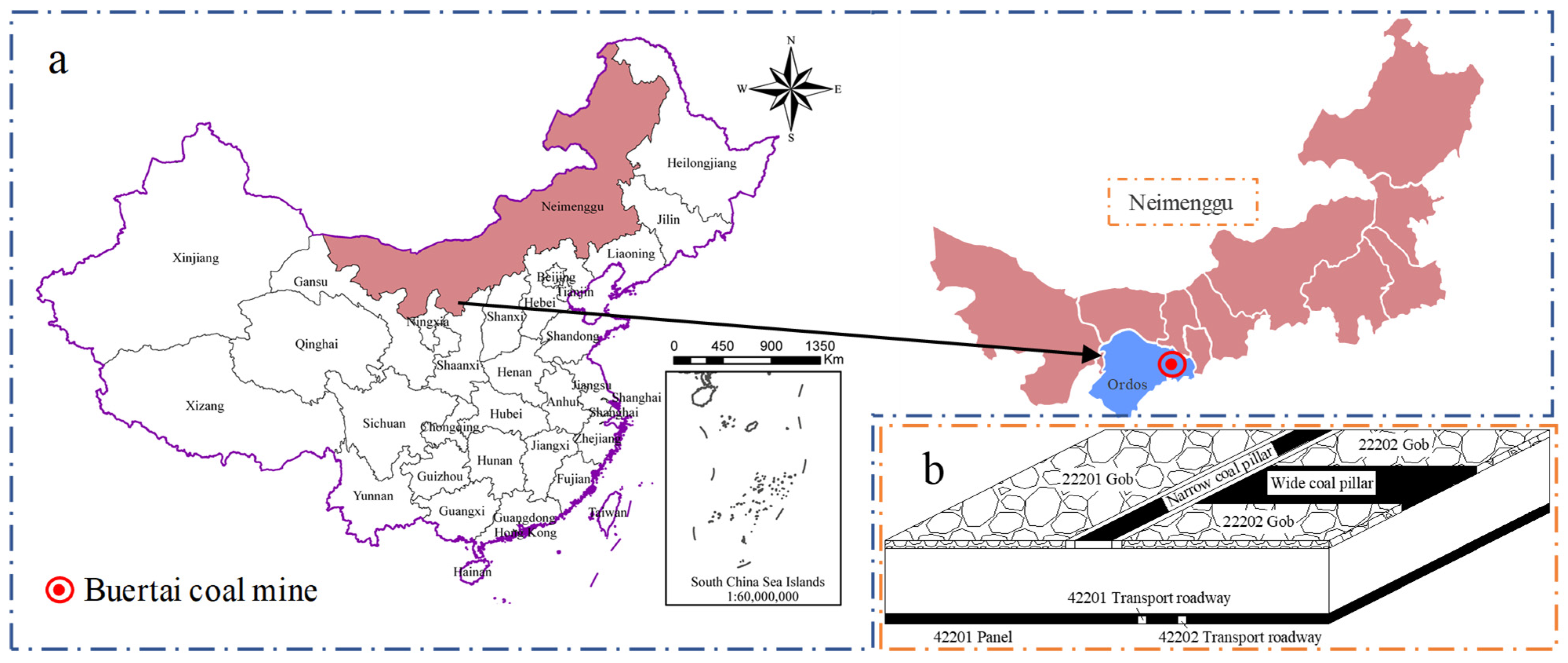
The Buertai Coal Mine has a simple geological structure, predominantly monoclines with gentle dip angles and no-fault development. The coal mine contains 9 mineable coal seams, and mainly the 2-2 and 4-2 coal seams are being mined now. The 2-2 coal seam is 3 m thick and 300 m deep on average. The 4-2 coal seam is 6.12 m thick and 368 m deep on average, and comprehensive mechanized top coal caving mining is adopted.
Stope mining at the two working faces of the overlying 2-2 coal seam, 22201 and 22202, has been completed, leaving a 20 m wide sectional coal pillar. Skip mining was carried out when stope mining the 22202 working face, leaving a 70 m skip mining coal pillar. The spatial layout of the two remaining coal pillars resembles a mutually perpendicular T-shape. The 42201 and 42202 working faces are below the 22201 and 22202 working faces, and the stope mining roadways of the adjacent working faces, i.e., the transport roadways of 42201 and 42202, are dug simultaneously, leaving a roadway-supporting coal pillar of certain width in the section. The location of the Buertai coal mine and schematic diagram of the 42202 stope layout is shown in
Figure 1.
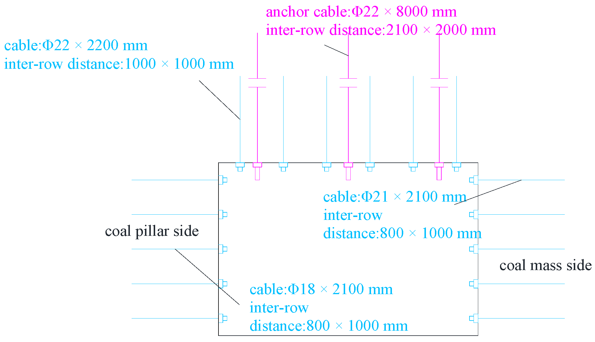
The original support design of the 42202 stope mining roadway is as follows. The roof is under the combined support by “left-hand thread rebar bolt without longitudinal bar + welded mesh + anchor cable + π-type steel strip”. The bolts are φ22 × 2200 mm in dimension and arranged rectangularly with six sets per row with an inter-row distance of 1000 × 1000 mm. The anchor cables are φ22 × 8000 mm in dimension and arranged rectangularly 3 sets per row with an inter-row distance of 2100 × 2000 mm. The coal pillar rib is under the combined support of “bolt + diamond-shaped mesh + wooden pallet”. The rebar bolts are φ22 × 2100 mm in dimension and arranged rectangularly in five sets per row with an inter-row distance of 800 × 1000 mm. The solid coal rib is under the combined support of “FRP bolt + double-layer high-strength plastic mesh + wooden pallet.” The bolts are φ22 × 2100 mm in dimension and arranged rectangularly in five sets per row with an inter-row distance of 800 × 1000 mm, as shown in
Figure 2.
During the stope mining at the working faces under the same working conditions, the stope mining roadways showed the following failure characteristics.
(1) When the stope mining roadway is only affected by a single sectional coal pillar in the overlying coal seam, the roof and floor displacements are between 200 and 220 mm, and the displacements of the two ribs are between 190 and 215 mm. When affected by approximately T-shaped remaining coal pillars, the displacements of the roadway roof and floor increase by 54.5–56% to 440–500 mm, and the displacements of the two ribs increase by 51.3–55.2% to 390–480 mm. Therefore, the deformation of the roadway below the T-shaped remaining coal pillar has increased significantly, and the surrounding rock failure is severe.
(2) On-site investigation shows that the force on the bolts in the roadway rib had a sudden stepwise decrease, and the pallet fell off. Thus, the range of surrounding rock plastic failure continuously increased under the effect of multiple disturbances, and the confining pressure of the bolt-supported section and rock mass integrity decreased, which significantly reduced the anchoring capacity of the bolts.
3. Methodology
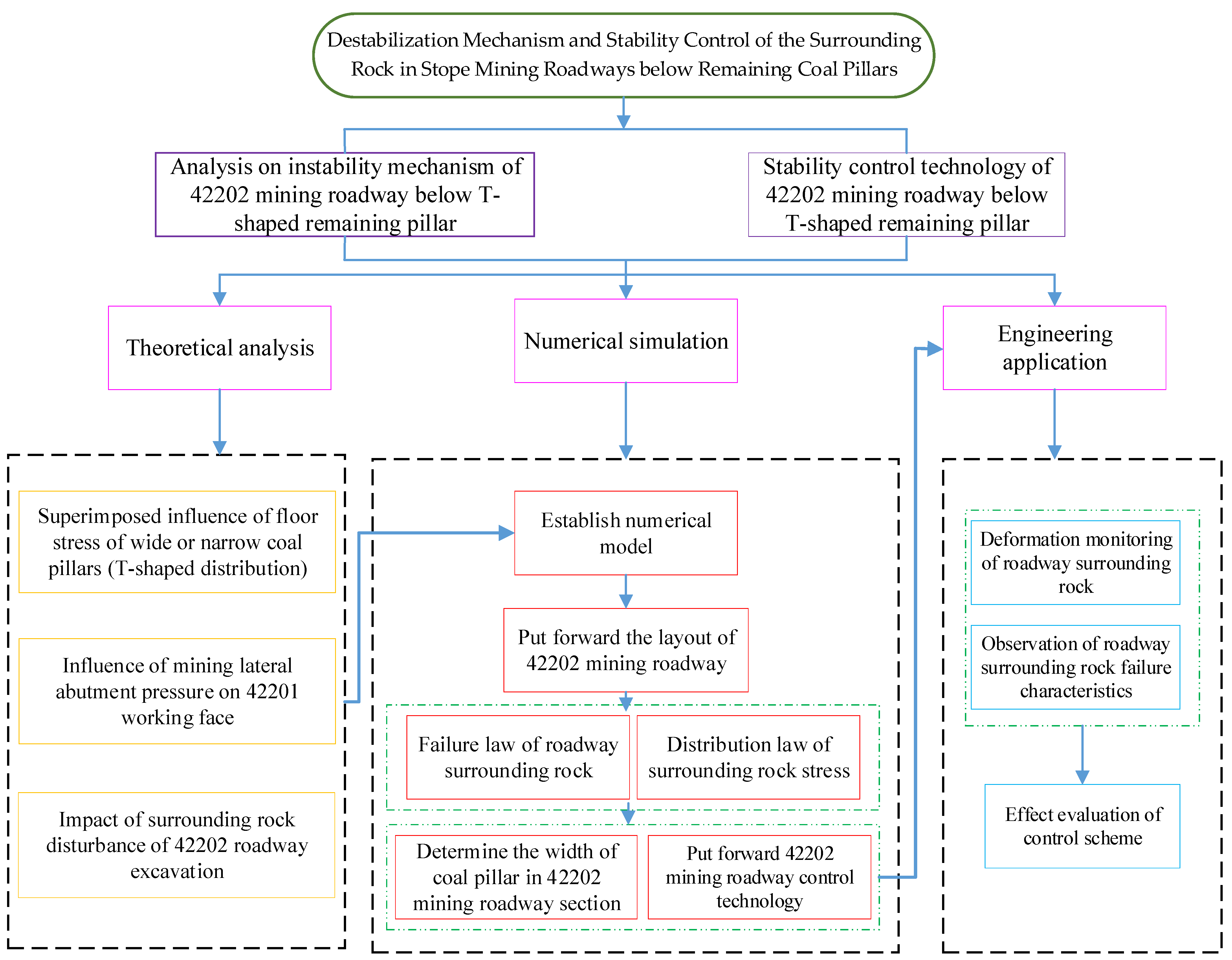
In this paper, theoretical analysis, numerical simulation and engineering application are used to study the instability mechanism and stability control technology of the surrounding rock of the mining roadway below the remaining coal pillar. The technical flowchart is shown in
Figure 3. The specific steps are as follows: (1) Through the theoretical analysis method, the superposition effect of T-shaped residual coal pillar on the abutment pressure of 4-2 coal seam in 2-2 coal seam of Buertai Coal Mine is studied, and combined with the Mohr-Coulomb criterion, the failure and instability mechanism of surrounding rock of 42202 mining roadway under multiple disturbances is revealed. (2) On the basis of theoretical analysis, an equal scale numerical model is established by using FLAC3D numerical software (version 6.00.74, Itasca, China, 2020) to simulate and analyze the surrounding rock plastic zone and vertical stress distribution characteristics of 42202 mining roadway under different layout schemes (different width section pillars), so as to propose the most reasonable section pillar retaining scheme, and propose the surrounding rock reinforcement support technology to control the roadway stability. (3) The scheme of section coal pillar reservation and the technology of surrounding rock reinforcement and support were applied in the 4-2 coal seam, and the effectiveness of the research results in this paper is verified through ground pressure monitoring.
3.1. Theoretical Analysis
3.1.1. Stress Distribution Pattern below Remaining Coal Pillars
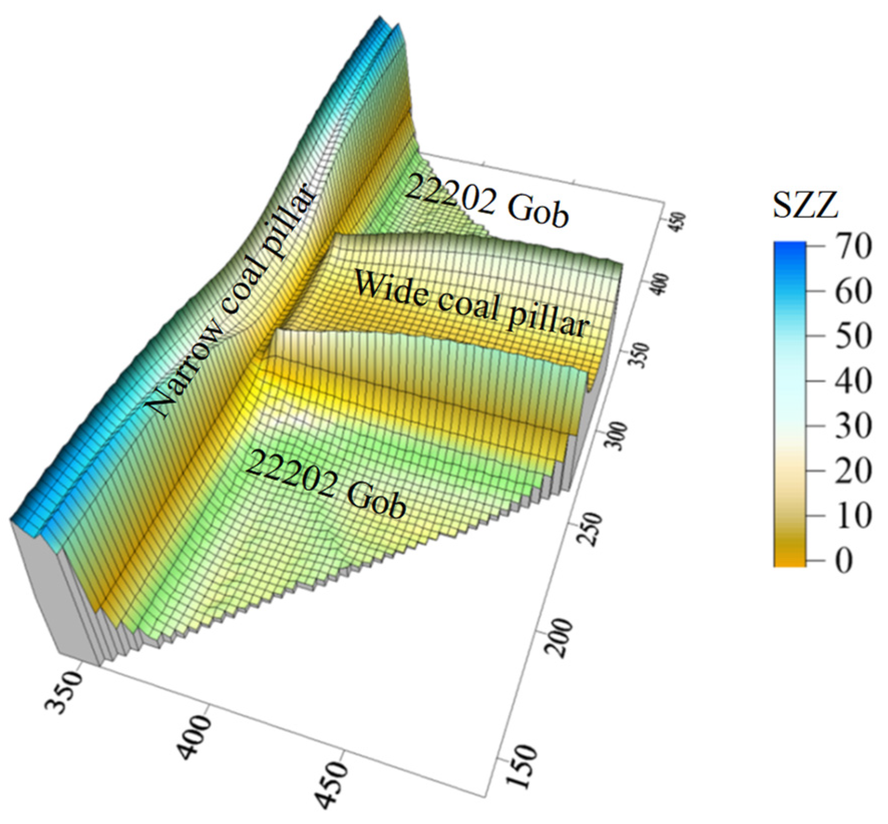
After the 2-2 coal seam was extracted, the rock formation above the gob collapsed, causing the abutment pressure on the remaining coal pillar to rise sharply. These stresses transferred to the underlying coal seam, forming a larger area under the effects of the coal pillar abutment stress, i.e., the rock mass below the coal pillar entered the high abutment pressure state earlier. The abutment pressure distribution on the T-shaped remaining coal pillar [
24] is shown in
Figure 4. When the coal pillar was narrow (20 m), the roof fracture position moved toward the inside of the coal pillar, i.e., the range of the limit equilibrium area of the coal pillar increased significantly. As a result, the vertical stress on the coal pillar increased significantly, peaking at 70 MPa. As the coal pillar became wider (70 m), the pressure-bearing range increased. The peak vertical stress decreased significantly compared with that of the narrow coal pillar, but the range of effects on the underlying coal seam was increased relatively.
To investigate the stress transfer pattern of the 2-2 coal seam to the underlying coal seam, the coal pillar abutment pressure can be simplified to the mechanical model shown in
Figure 5. Since the abutment pressure is symmetrically distributed on the wide coal pillar about its center axis, the center of the wide coal pillar is selected as the coordinate origin. For the narrow coal pillar, the minimum stress point in the internal elastic core is selected as the coordinate origin. The horizontal cross-sectional direction of the coal seam floor is selected as the x-axis direction, and the vertically downward direction is selected as the y-axis direction. γ is the volumetric weight of the rock, H is the depth, and
k1,
k2,
k3,
k4, and
k5 are the maximum stress concentration factors.
In the figure, ①–⑩ are stress-concentrated areas of the coal pillar, and the vertical stress components of the floor rock mass are:
where
q is the micro-element load collection degree, and
σy is the vertical stress (MPa);
x and
y are the vertical and horizontal distances of the concentrated force q to any point M on the floor (m).
As shown in
Figure 5, the additional stress generated by the coal pillar at point M on the underlying coal seam is calculated based on the superposition principle, and the calculation results are as follows.
The additional vertical stress generated by the wide coal pillar is:
where
,
,
,
,
,
, and
y is the coal seam spacing.
The additional vertical stress generated by the narrow coal pillar is:
where
,
,
,
.
3.1.2. The Effects of Working Face Mining on the Roadway Surrounding Rock
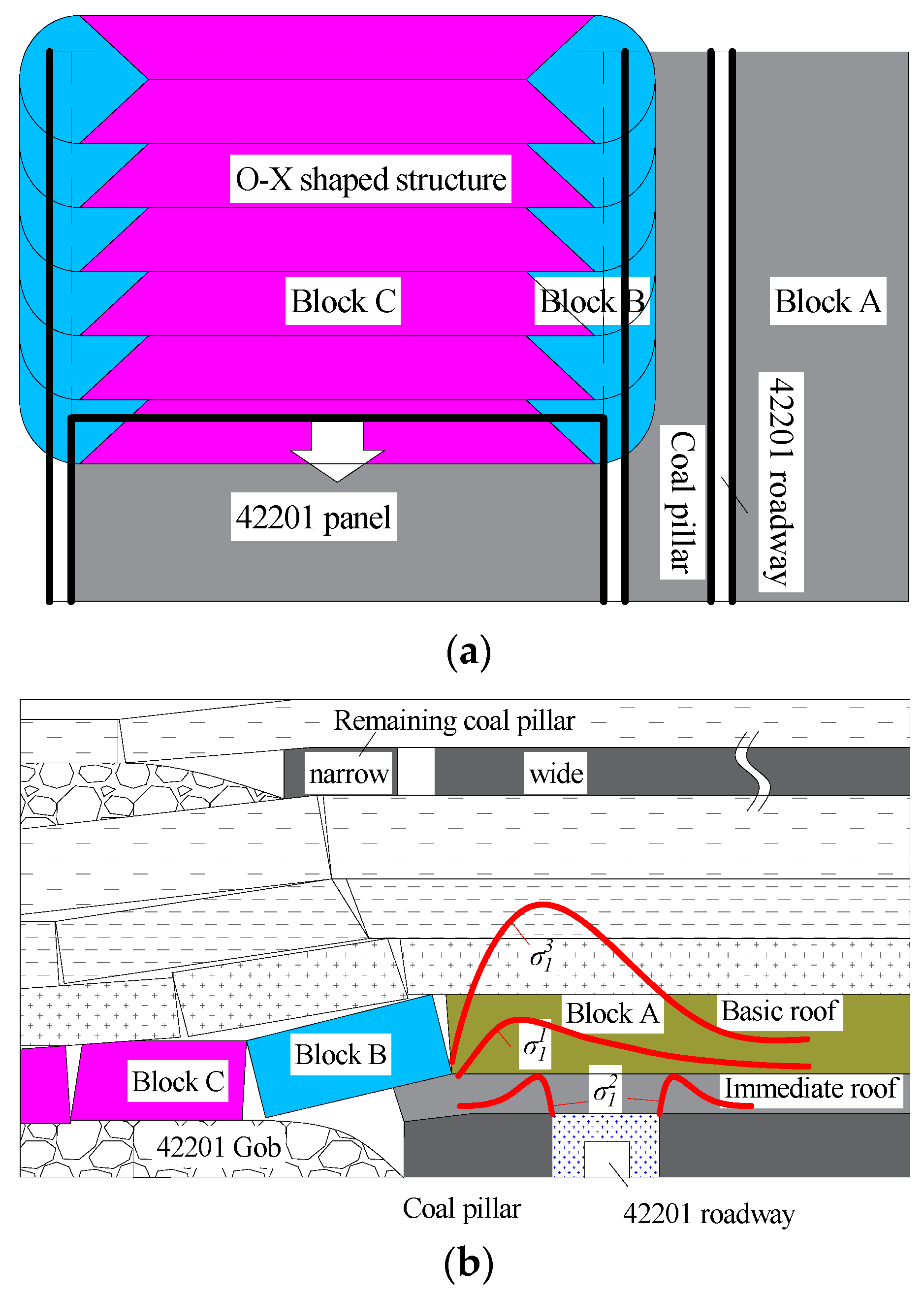
The 42202 transport roadway was affected by the stress transfer from the floor of the coal pillar in the overlying coal seam and the lateral abutment pressure generated in the stope mining process of the adjacent 42201 working face, respectively. The structural evolution of the overlying roof rock of the 42201 working face is shown in
Figure 6a. After the coal seam is mined, the overlying rock structure of the gob roof fails, and the stress state is changed significantly. With the continuous advancement of the working face, the scope of the gob increases, and the immediate roof fracture and expand to fill the gob. As “O-X” periodic fracture occurs in the main roof, block B forms an arc triangle with the sectional coal pillar. One end of rock block B rotates and contacts the gangue in the gob, and the other end breaks off inside the rib of the sectional coal pillar. Despite the rotation and sinking, rock block B interlocks with rock block C and rock mass A, forming a hinge “macrostructure” [
25,
26]. In this process, the static force system transferred by the overlying remaining coal pillar is
; The static force system generated by roadway surrounding rock excavation disturbance is
; The lateral abutment pressure system due to mining at the 42201 working face is
. Therefore, the total stress on the roadway surrounding rock
can be expressed as
, as shown in
Figure 6.
A micro-element from the roadway rib shown in
Figure 6b is selected for analysis. The surrounding rock stress states before and after multiple disturbances and the effect on its stability are illustrated in
Figure 7.
(1) Before the disturbance from coal seam mining, the original rock stress is distributed in the rock seam. According to field measurements [
27], the ratio of the maximum principal stress
to the minimum principal stress
is approximately 1.3, i.e., the difference between the tangential stress and the radial stress is small. Thus, the diameter of the Mohr’s circle
representing the stress state is very small and below the strength envelope
L1.
(2) As the overlying coal seam (2-2 coal seam) is mined, the tangential stress in the rock mass increases from to due to the stress transfer of the remaining coal pillar abutment pressure, and the underlying coal seam enters a high pressure-bearing state.
(3) At the moment of excavation and unloading of the 42202 stope mining roadway, the radial stress around the perimeter of the roadway decreases from to and decreases to zero at the roadway surface. However, the tangential stress in the surrounding rock increases rapidly from to . Thus, the radius of the Mohr’s circle increases significantly, and the Mohr’s circle exceeds the strength envelope L1. It is thus evident that great deviatoric stress is generated in the surrounding rock after the roadway excavation, resulting in plastic failure of the surrounding rock.
(4) After the stope mining at the 42201 working face, the key stratum of the roof rock shows rotary movements. Due to the superposition of lateral abutment pressure transfer, the tangential stress of the surrounding rock increases sharply from to , and the plastic failure of the surrounding rock is intensified. In addition, after the large-scale compression-shear failure of the surrounding rock, dislocation failure occurs in the failure area along the shear surface. The strength of the rock mass decreases significantly in the plastic area, and the bearing capacity decreases. At this point, the rock strength envelope develops from line L1 to line L2.
3.1.3. Reinforcement Support for Stope Mining Roadway
The original support of the 42202 stope mining roadway mainly include bolts and anchor cables. According to the above numerical simulation results, when the coal pillar width is between 25 and 30 m, the plastic area in the roof is 2.5 m, and that in the two ribs is 3.0 to 3.5 m. Supported with anchor cables 6.3 m long, the bearing capacity is sufficient for the deep surrounding rock. Thus, the surrounding rock of the roof has good stability. The two ribs are only supported by bolts 2.1 m long, and the full length of the bolts is within the plastic area. As a result, the surrounding rock of the supported section has a relatively small confining pressure, and the support capacity of the bolts is greatly reduced, rendering the surrounding rock prone to overall instability. Therefore, in addition to leaving reasonable coal pillars and pressure relief, reinforcement support must be applied to the surrounding rocks of the two ribs to improve their stability and bearing capacity.
The following key issues should be noted when applying reinforcement support [
28].
(1) The anchorage blind area of the weak coal mass must be controlled. The anchorage blind area is in the shallow triangle between the compression areas (
Figure 8), and the deformation and loosening of the coal mass in this area weaken the bolt support force, forming a vicious circle. Appropriate increase in bolt density and the use of bolt and metal strip combination support are the main methods to control the anchorage blind areas. Higher bolt density reduces the range of the anchorage blind area, while steel strips spread the bolt supporting force to the shallow rock mass, thus restraining the deformation of the anchorage blind area.
(2) The bolt-supported area has low load-bearing capacity. Considering the relatively large range of the plastic area in the surrounding rock, it is difficult for the bolts to penetrate deeply into the stable rock mass. At this time, the main function of the bolts is to form the loose surrounding rock into a supporting structure with sound stability. However, long-term stability requires combining long and short bolt support, i.e., establishing a foundation bearing ring with short bolts in the shallow part and a thick reinforcing ring in the deep part with long anchor cables. Thus, the reinforced bolt-supported area is linked to the deep stable rock, and the range of the surrounding rock-bearing ring is expanded. Consequently, fracture interconnection and loosening fragmentation failures in the shallow surface are prevented, and a deep bolt layer is formed to resist disturbance, as shown in
Figure 9.
3.2. Numerical Simulation
Based on the actual situation of the working face and the roadway at the site, a 770 m × 600 m × 175 m numerical model was established using the finite difference software FLAC3D, as shown in
Figure 10. The vertical movement is restricted at the bottom of the model, and the horizontal movement is restricted at the front, rear, and both ends. The overlying rock unit weight is replaced with a uniform load of 9.6 MPa applied on the top of the model, and the lateral pressure coefficient is set to 1.3 [
27]. The coal seam was simulated with the Mohr-Coulomb model, and the initial support components of the roadway were simulated using FLAC3D built-in structural units.
The simulation scheme and process are as follows. (1) Application of initial ground stress and initial equilibration. (2) Progressive excavation of the 22201 and 22202 working faces. (3) In order to investigate the effects of the overlying remaining coal pillar and the adjacent 42201 working face on the 42202 stope mining roadway, the 42202 roadway was excavated when the coal pillar width was 10, 15, 20, 25, and 30 m and immediately supported after excavation. (4) The 42201 working face was gradually excavated after equilibrium calculation until the coal seam excavation was completed.
4. Results
4.1. Results of Theoretical Analysis
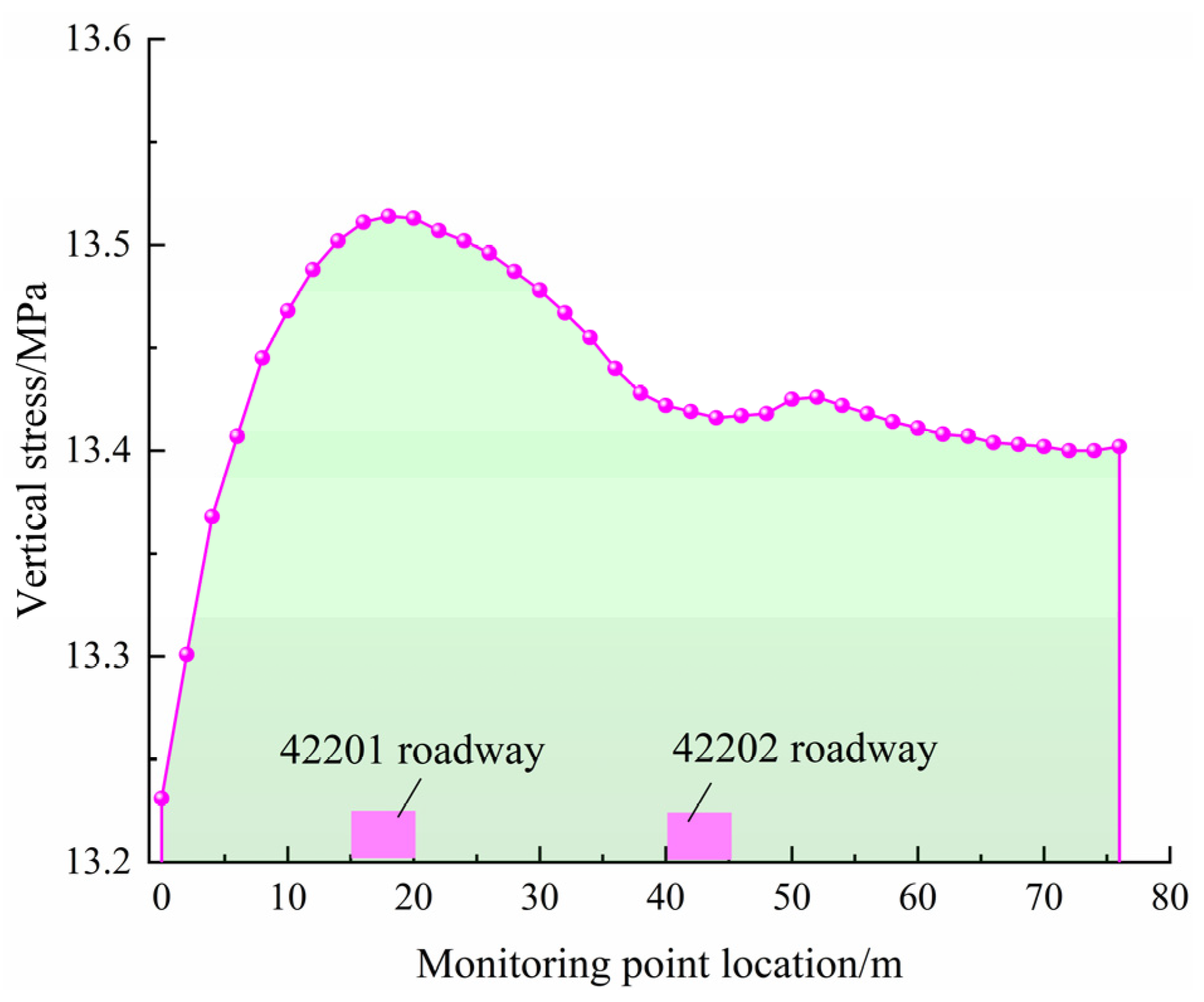
Taking the location of the 42202 stope mining roadway below the T-shaped remaining coal pillar as an example, the vertical stress distribution directly below the T-shaped remaining coal pillar (inclined to the profile along the working face) calculated based on the stress distribution model in
Figure 5 and Equations (2) and (3) is shown in
Figure 11, and the vertical stress can be obtained as approximately 13.45 MPa. Therefore, the location of the roadway is affected by the abutment pressure transfer of the overlying coal pillar, and the vertical stress in the surrounding rock has reached 1.4 times the original rock stress before roadway excavation in the underlying coal seam.
In addition to effectively improving the roadway stability and reducing the surrounding rock maintenance cost, the reasonable coal pillar size also greatly reduces the waste of coal resources. The surrounding rock of reusable roadways is generally affected by the superimposed disturbance from roadway excavation and stope mining at the adjacent working faces, especially with roadways below remaining coal pillars. Therefore, the sectional coal pillar size in the underlying working face should be fully considered and designed.
In accordance with conventional coal pillar width determination methods, an elastic core area of 2 times the mining height should be reserved in the middle of the coal pillar during the service of the roadway. Considering the above numerical simulation results, the distribution range of abutment pressure from the remaining coal pillar and adjacent working face, a reasonable roadway should avoid the peak superimposed abutment pressure area and be arranged in the pressure-reducing section. Therefore, the coal pillar width should not fall below 20 m.
4.2. Results of Numerical Simulation
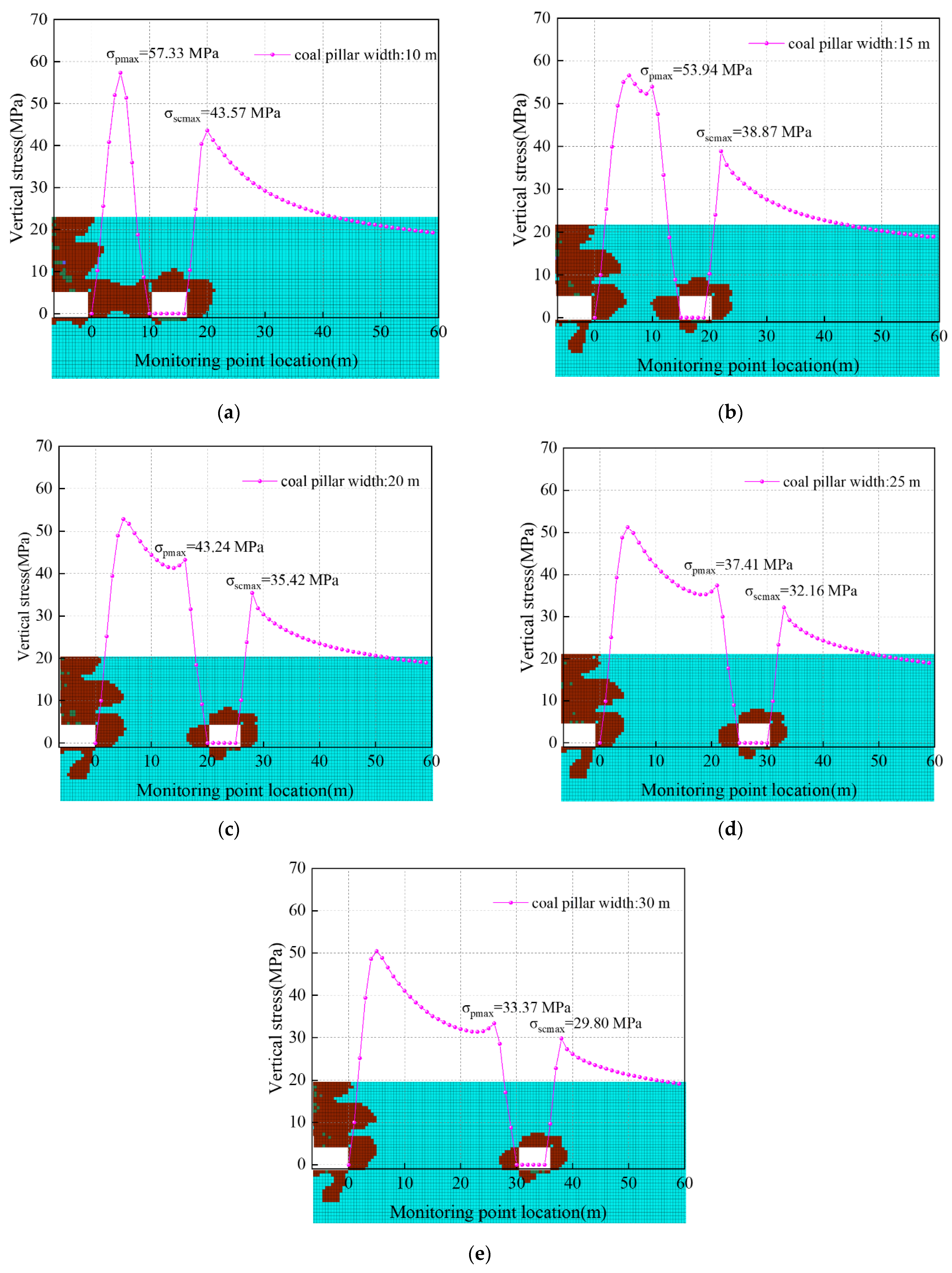
Figure 12 shows the distribution of vertical stress and plastic area in the two ribs of the 42202 auxiliary transport roadway after mining at the 42201 working face. The red area and blue area indicate the plastic yielding and elastic states of the roadway surrounding rock, respectively. Parameters σ
pmax and σ
scmax indicate the peak vertical stresses in the coal pillar rib and the coal mass rib.
As shown in
Figure 12, the plastic area of the roadway surrounding rock and the stress concentration of the two ribs show significant decreasing trends with the increase of coal pillar width. According to
Figure 12a, plastic failures, mainly shear failures, occur diagonally across the whole coal pillar when the coal pillar width is 10 m. The peak vertical stress in the coal pillar rib is 57.33 MPa in its middle. The peak vertical stress of the coal mass rib is 43.57 MPa and about 4.0 m from the surface of the roadway. The stress concentration coefficients of the two ribs are 5.97 and 4.54, respectively. Therefore, the roadway is in the stress elevation area formed by the T-shaped remaining coal pillar in the overlying coal seam and the mining at the adjacent working face. As a result, the surrounding rock is subjected to great deviatoric stress, leading to a large number of cracks and a wide range of plastic failures. In the meantime, the coal pillar has a relatively large bearing capacity but is highly unstable after fracture and compaction.
According to
Figure 12b, when the coal pillar width is increased to 15 m, the plastic failure does not penetrate the coal pillar, and an elastic core area of about 4.0 m appears in its middle. Compared with those at the coal pillar width of 10 m, the peak vertical stress of the coal pillar rib is reduced by 3.39 MPa, and that of the coal mass rib is reduced by 4.7 MPa. The stress concentration coefficients of the two ribs are 5.62 and 4.05, respectively. The large stress difference between the two ribs causes the asymmetrical distribution of the plastic area, and the surrounding rock failure is severe.
According to
Figure 12c–e, the elastic core area of the coal pillar rib keeps increasing while the range of surrounding rock failure gradually decreases with the increasing coal pillar width. When the coal pillar width is 20–30 m, the plastic area of the coal pillar rib is 3.5 to 4.0 m, and the plastic area of the coal mass rib is about 3.0 m. The vertical stress distribution on the coal pillar evolves from a single-peak shape to an asymmetric double-peak shape, the stress concentration tends to decrease, and the peak stress difference between the two roadway ribs gradually decreases. The reason is that as the coal pillar width increases, the roadway gradually avoids the superimposed stress elevation area, resulting in a decreased load on the surrounding rock and increased roadway stability. Combining the results in
Section 4.1, the width of the coal pillar in the 42202 mining roadway section should be 25 m.
4.3. Industrial Testing
4.3.1. Scheme of Reinforcement Support
Impacted by the mining, rib spalling and support failure were observed in the roadway. According to the above study, the depth of plastic failure in the surrounding rock of the 42202 auxiliary transport roadway after being disturbed by the first stope mining gradually exceeds the range of bolt support, and the bolt support of the two ribs has basically failed during the secondary stope mining. Thus, it is necessary to strengthen the support of the two ribs. According to the principle of asymmetric support, the solid coal rib was supported with 28.6 mm × 6500 mm anchor cables, and two rows of anchor cables with a spacing of 2000 mm were installed at the rib part together with 300 × 300 × 16 mm pallets. The coal pillar rib was first supported with 22 mm × 6500 mm anchor cables, and two rows of anchor cables with a spacing of 2100 mm were added together with 4600 × 140 × 8 mm π-steel strips. In addition, a row of 28.6 mm × 6500 mm anchor cables with a spacing of 2100 mm were added together with 4600 × 140 × 8 mm π-steel strips, as shown in
Figure 13.
In order to verify the stability control effect of bolting support technology on 42202 transportation roadway, the plastic zone state of surrounding rock before and after bolting support was compared by numerical simulation software, as shown in
Figure 14. According to
Figure 14b, when the width of the coal pillar is set as 25 m and anchor cable reinforcement support technology is adopted, the plastic range of the two walls of surrounding rock is 2.0 m at most. Compared with that before support, the plastic zone of the coal pillar is reduced by about 1.5 m and the solid wall is reduced by about 1.0 m. It can be seen that the use of anchor cable reinforcement support can effectively prevent the plastic destruction of surrounding rock and fully ensure the stability of the mining roadway.
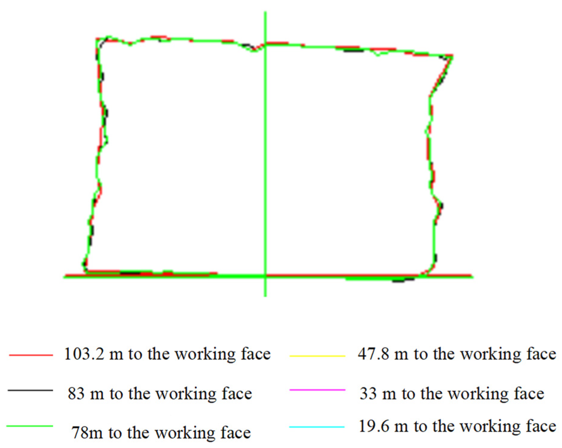
4.3.2. Displacement Monitoring of Roadway Surface
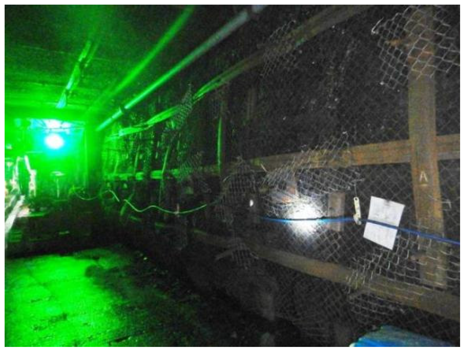
Based on the sectional coal pillar retaining scheme and the roadway surrounding rock anchor reinforcement support technology proposed in this paper, the experiment was carried out in the 42202 mining roadway. Multiple on-site full-section scanning monitoring tasks were conducted on the 42202 auxiliary transport roadway directly below the skip mining coal pillar during the second stope mining. The results are shown in
Figure 15, where the roadway deformation remains basically the same as the working face advances. In the meantime, no significant mine pressure behaviors, including large deformation, rib spalling, and roof fall, are observed at the site, as shown in
Figure 16. Therefore, the adopted control techniques can well control the destabilization of the roadway below the remaining coal pillar after multiple mining processes, thus ensuring safe and efficient production at the working face.
5. Conclusions
(1) Affected by the T-shaped remaining coal pillar in the 2-2 coal seam, the vertical stress at the stope mining roadway of the underlying 4-2 coal seam increased sharply, reaching a stress concentration coefficient of up to 1.4 times. In addition, the superimposed effect of lateral high abutment pressure generated during stope mining at the 42201 working face caused great deviatoric stress in the coal mass, and the radius of Mohr’s circle of the stress increased significantly. After roadway excavation and unloading, the surrounding rock is prone to wide-range compression-shear failures. Thus, the peak lateral pressure area should be avoided.
(2) Based on the on-site engineering conditions, numerical simulation software was applied to obtain the stress characteristics and plastic area development pattern in the surrounding rock of the 42202 stope mining roadway below the T-shaped remaining coal pillar. As the width of the sectional coal pillar in the 4-2 coal seam increased, the stress curve of the surrounding rock shifted from single-peaked to asymmetrically double-peaked, and the stress concentration coefficient gradually decreased. Meanwhile, the stress difference between the two ribs of the roadway showed a decreasing trend, and the failure mode of the coal pillar changed from penetrating failure to only producing a 2.5 to 3.0 m plastic area. The large vertical stress increase in the surrounding rock was the main reason for the failure and destabilization of the roadway.
(3) Considering the high-stress area under the T-shaped remaining coal pillar, the sectional coal pillar width in the 42202 mining roadway is 25 m. In the meantime, the asymmetric reinforcement anchor cable support technology for both sides of the roadway is proposed. Based on the numerical calculation verification, it is believed that the scheme reduces the plastic zone of surrounding rock by 1.0–1.5 m, which can effectively maintain the stability of the roadway.
(4) On-site industrial testing showed that the roadway deformation of the 42202 stope roadway was small and basically constant, and no rib spalling or roof fall was observed, thus achieving the stability control of the stope mining roadway below the remaining coal pillar.
Author Contributions
All authors contributed to this paper. Conceptualization, Q.F. and K.Y.; methodology, Q.F.; software, Y.W.; validation, Q.F. and Z.W.; formal analysis, Q.L.; data curation, Q.F.; writing—original draft preparation, Q.F.; writing—review and editing, Q.L. and K.Y.; validation, X.H. and Q.L.; funding acquisition, K.Y. All authors have read and agreed to the published version of the manuscript.
Funding
This work is supported by the Collaborative Innovation Project of Universities in Anhui Province (GXXT-2019-029), the Institute of Energy, Hefei Comprehensive National Science Center under Grant (No. 21KZS215), Major special projects of science and technology in Shanxi Province (No. 20191101016), Open Research Grant of Joint National-Local Engineering Research Centre for Safe and Precise Coal Mining (Grant NO. EC2021014).
Data Availability Statement
The data used for conducting classifications are available from the corresponding author authors upon request.
Conflicts of Interest
The authors declared no potential conflict of interest with respect to the research, authorship, and publication of this article.
References
- Sun, X.; Liu, Y.; Wang, J.; Li, J.; Sun, S.; Cui, X. Study on three-dimensional stress field of gob-side entry retaining by roof cutting without pillar under near-group coal seam mining. Processes 2019, 7, 552. [Google Scholar] [CrossRef]
- Zhao, T.-B.; Guo, W.-Y.; Tan, Y.-L.; Yin, Y.-C.; Cai, L.-S.; Pan, J.-F. Case studies of rock bursts under complicated geological conditions during multi-seam mining at a depth of 800 m. Rock Mech. Rock Eng. 2018, 51, 1539–1564. [Google Scholar] [CrossRef]
- Chi, X.; Yang, K.; Wei, Z. Breaking and mining-induced stress evolution of overlying strata in the working face of a steeply dipping coal seam. Int. J. Coal Sci. Technol. 2021, 8, 614–625. [Google Scholar] [CrossRef]
- Wang, H.; Jiang, Y.; Zhao, Y.; Zhu, J.; Liu, S. Numerical investigation of the dynamic mechanical state of a coal pillar during longwall mining panel extraction. Rock Mech. Rock Eng. 2013, 46, 1211–1221. [Google Scholar] [CrossRef]
- Tan, Y.L.; Zhao, T.B.; Xiao, Y.X. In situ investigations of failure zone of floor strata in mining close distance coal seams. Int. J. Rock Mech. Min. Sci. 2010, 47, 865–870. [Google Scholar] [CrossRef]
- Ning, J.; Wang, J.; Tan, Y.; Xu, Q. Mechanical mechanism of overlying strata breaking and development of fractured zone during close-distance coal seam group mining. Int. J. Min. Sci. Technol. 2020, 30, 207–215. [Google Scholar] [CrossRef]
- Li, Q.; Wu, G.; Kong, D. Study on Stability of Stope Surrounding Rock under Repeated Mining in Close-Distance Coal Seams. Geofluids 2022, 2022, 9630942. [Google Scholar] [CrossRef]
- Zhou, A.; Hu, J.; Gong, W.; Wang, K.; Deng, N.; Wu, J. The instability criticality and safety factor of coal-gas outburst induced by shear failure based on limit analysis. Fuel 2021, 303, 121245. [Google Scholar] [CrossRef]
- Yang, K.; Fu, Q.; Liu, Q.; He, X.; Lyu, X. Evolution of Mining-Induced Stress in Downward Mining of Short-Distance Multiseam. Geofluids 2022, 2022, 3305734. [Google Scholar] [CrossRef]
- Chen, D.; Wu, Y.; Xie, S.; Guo, F.; He, F.; Liu, R. Reasonable location of stopping line in close-distance underlying coal seam and partition support of large cross-section roadway. Int. J. Coal Sci. Technol. 2022, 9, 1–22. [Google Scholar] [CrossRef]
- Bai, J.-B.; Shen, W.-L.; Guo, G.-L.; Wang, X.-Y.; Yu, Y. Roof deformation, failure characteristics, and preventive techniques of gob-side entry driving heading adjacent to the advancing working face. Rock Mech. Rock Eng. 2015, 48, 2447–2458. [Google Scholar] [CrossRef]
- Liu, W.; Yang, K.; Zhen, W.; Chi, X.; Xu, R.; Lv, X. Energy Dissipation and Failure Characteristics of Layered Composite Rocks under Impact Load. Shock. Vib. 2021, 2021, 8775338. [Google Scholar] [CrossRef]
- Wei, Z.; Yang, K.; He, X.; Zhang, J.; Hu, G. Experimental Study on the Optimization of Coal-Based Solid Waste Filling Slurry Ratio Based on the Response Surface Method. Materials 2022, 15, 5318. [Google Scholar] [CrossRef] [PubMed]
- Zhang, Z.; Deng, M.; Wang, X.; Yu, W.; Zhang, F.; Dao, V.D. Field and numerical investigations on the lower coal seam entry failure analysis under the remnant pillar. Eng. Fail. Anal. 2020, 115, 104638. [Google Scholar] [CrossRef]
- Xinqiu, F.; Minjiang, G.; Zhiqiang, L. Instability mechanism and prevention of roadway under close-distance seam group mining. Chin. J. Rock Mech. Eng. 2009, 28, 2059–2067. [Google Scholar]
- Xinjie, L.; Xiaomeng, L.; Weidong, P. Analysis on the floor stress distribution and roadway position in the close distance coal seams. Arab. J. Geosci. 2016, 9, 83. [Google Scholar] [CrossRef]
- Sun, Z.; Wu, Y.; Lu, Z.; Feng, Y.; Chu, X.; Yi, K. Stability analysis and derived control measures for rock surrounding a roadway in a lower coal seam under concentrated stress of a coal pillar. Shock. Vib. 2020, 2020, 6624983. [Google Scholar] [CrossRef]
- Zhang, Z.; Deng, M.; Bai, J.; Yan, S.; Yu, X. Stability control of gob-side entry retained under the gob with close distance coal seams. Int. J. Min. Sci. Technol. 2021, 31, 321–332. [Google Scholar] [CrossRef]
- Jiang, F.X.; Wang, Y.X.; Ling, M.; Yang, Y. Mechanism of rock burst occurring in protected coal seam induced by coal pillar of protective coal seam. Chin. J. Geotech. Eng. 2017, 39, 1689–1696. [Google Scholar]
- Liu, H.; Zhang, B.; Li, X.; Liu, C.; Wang, C.; Wang, F.; Chen, D. Research on roof damage mechanism and control technology of Gob-side entry retaining under close distance gob. Eng. Fail. Anal. 2022, 138, 106331. [Google Scholar] [CrossRef]
- Xia, Z.; Yao, Q.; Meng, G.; Xu, Q.; Tang, C.; Zhu, L.; Wang, W.; Shen, Q. Numerical study of stability of mining roadways with 6.0-m section coal pillars under influence of repeated mining. Int. J. Rock Mech. Min. Sci. 2021, 138, 104641. [Google Scholar] [CrossRef]
- He, F.; Lv, K.; Li, X.; Qin, B.; Li, L. Failure mechanism and control of lower retracement channel in close-distance double-thick coal seams. Shock. Vib. 2021, 2021, 6651099. [Google Scholar] [CrossRef]
- Du, F.; Wang, K.; Guo, Y.; Wang, G.; Wang, L.; Wang, Y. The mechanism of rockburst-outburst coupling disaster considering the coal-rock combination: An experiment study. Geomech. Eng. 2020, 22, 255–264. [Google Scholar]
- Ju, J.; Xu, J.; Zhu, W. Longwall chock sudden closure incident below coal pillar of adjacent upper mined coal seam under shallow cover in the Shendong coalfield. Int. J. Rock Mech. Min. Sci. 2015, 77, 192–201. [Google Scholar] [CrossRef]
- Cao, Z.Z.; Zhou, Y.J. Research on coal pillar width in roadway driving along goaf based on the stability of key block. Cmc-Comput. Mater Contin 2015, 48, 77–90. [Google Scholar]
- Ahmadi, M.E.; Mesroghli, S.; Hedayat, B.; Nazerian, H.; Shirazi, A.; Shirazy, A. Assessment of the Influence of Sulfuric Acid/Hydrogen Peroxide Mixture on Organic Sulfur Reduction of High Sulfur Coals and Their Chemical Composition. Open J. Geol. 2022, 12, 199–214. [Google Scholar] [CrossRef]
- Lu, K.; Deng, Z.G.; Feng, J.C. Surrounding rock failure mechanism of reserved roadway under superimposed mining and its control technology. J. Min. Saf. Eng. 2019, 36, 685–769. [Google Scholar]
- Han, C.L.; Zhang, N.; Kan, J.G.; Ran, Z. Mechanism and application of double active control with pressure-relieving and an choring for gob-side entry retaining. J. China Coal Soc. 2017, 42, 323–330. [Google Scholar]
| Publisher’s Note: MDPI stays neutral with regard to jurisdictional claims in published maps and institutional affiliations. |
© 2022 by the authors. Licensee MDPI, Basel, Switzerland. This article is an open access article distributed under the terms and conditions of the Creative Commons Attribution (CC BY) license (https://creativecommons.org/licenses/by/4.0/).


 ,
, 


