1. Introduction
In the products of solid propellant combustion, along with the gas-phase component, there are solid and liquid combustion products of metal powders [
1,
2]. Simulation of two-phase flows of combustion products plays an important role in the study of intra-chamber processes in solid propellant rocket motors (SRM). The addition of solid particles to the flow complicates the flow pattern, which is associated with a variety of properties (inertia and concentration) of dispersed particles, which lead to the implementation of numerous flow regimes [
3]. The concentration of particles is one of the main physical parameters that determine the characteristics of the movement of the dispersed phase, as well as the degree of its influence on the fluidflow [
4]. In a dispersed medium, zones free of particles (fragmentation of the phase volume) and regions with intersecting particle trajectories can appear, at the boundaries of which the concentration of the dispersed phase increases sharply [
5].
Analytical solutions of the Euler or Navier–Stokes equations contribute to a better understanding of the qualitative features of stationary and non-stationary flows. They allow estimating the domain of applicability of simplified mathematical models (inviscid fluid, slow flows, boundary layers) and are indispensable for validation of numerical and approximate methods. In the approaches developed in [
6,
7,
8], self-similar solutions of the continuity equation and the momentum equations are found under the assumption of a linear dependence of the axial velocity on one of the spatial coordinates and uniform injection from the channel walls. An experimental validation of the analytical solution corresponding to the vortical flow of an inviscid incompressible fluid is carried out in [
9,
10,
11,
12], in which measurement data were obtained from the distributions of axial velocity and pressure at various Reynolds numbers.
The influence of compressibility increases at a sufficiently large distance from the inlet section of the channel, which leads to the filling of the axial velocity profile [
12,
13]. Turbulence has a rather weak effect on the structure of the mean flow, with the exception of the region adjacent to the outlet section of the channel, where there is a significant acceleration of the flow, and the mean velocity profile becomes flatter [
11]. The movement of the burning surface of the channel (the effect of non-stationarity of the process) has a comparatively weak effect on the velocity and pressure distributions [
14]. The presence of a laminar flow region, which occupies the entire flow region (depending on the Reynolds number), is confirmed by [
15,
16].
To find a class of analytical solutions describing the flow of a viscous incompressible fluid in channels induced by fluid injection, methods of group analysis [
17] are applied. The stability of the flow in a semi-infinite round pipe with a closed left end is considered in [
18].
To take into account the influence of particles on the fluid flow, a joint calculation of the motion of the fluid and dispersed phases is required. Under certain restrictions on the particle size (the Stokes law for the particle drag) and the geometry of the computational domain (plane or axisymmetric channel), it is possible to construct analytical or approximate solutions that are convenient for making qualitative estimates and verifying numerical calculations. The mode of single particles is one of the simplest modes of particle-laden flow, which is realized at a low concentration of the dispersed phase. Obtaining new solutions is associated with the use of new dependencies describing the fluid flow and taking into account the influence of additional forces. Analytical or approximate solutions describing the motion of particles make it possible to find the limiting trajectory of particles (separatrix), to study the features of the concentration of the dispersed phase and their deposition on the wall [
19,
20].
Investigations of flows with particles in combustion chambers are related to the modeling of slagging of sections of the channel [
21,
22], combustion of aluminum particles [
23,
24], transport of particles by vortical structures and their interaction with an oscillating flowfield [
25,
26], and combustion instability [
27,
28]. The particle motion in channels with fluid injection and their influence on the characteristics of the carrier flow are studied in [
29,
30,
31,
32]. The motion of a particle in a propellant channel is considered in [
33,
34], in which an approach that simplifies the implementation of mathematical models of two-phase flows is proposed.
This study presents analytical solutions of equations describing the motion of an individual particle in a channel with fluid injection from walls, as well as the results of a numerical simulation of particle motion under the influence of non-turbulent factors. The influence of gravitational force on the motion of a particle is discussed and the domains of their applicability are investigated. The combustion surface is modeled by the injection surface of a mixture of fluid and particles, the parameters of which are known and do not depend on the place of injection and the presence of body forces.
2. Flow Induced by Fluid Injection
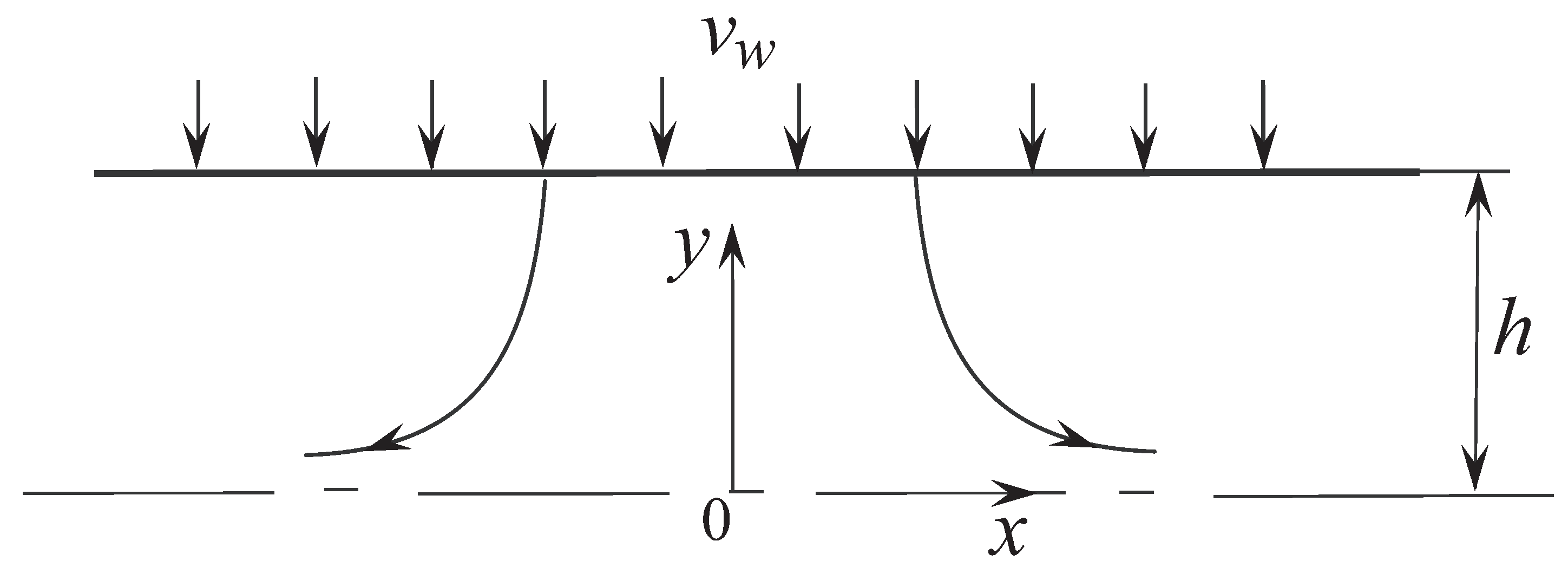
A flow in a circular channel, formed by injection of a mixture of fluid and dispersed particles with given parameters along the normal to the channel surface is considered. Flow is in a potential field of body forces, the vector of which is normal to the centerline of the channel. This model describes a gas-particle flow in a horizontal channel in the presence of gravity. It is assumed that the gravitational effects do not altered flowfield. The affect particle motion only.
A quasi-developed flow of a viscous incompressible fluid in a sufficiently long cylindrical channel with fluid injection is simulated, when the flow quantities, normalized on the velocity on the channel centerline, change slightly along its length. Fluid injection is uniformly distributed along cylindrical wall. The
x axis is aligned with the centerline of the channel, and the
y axis is normal to it (
Figure 1). The radius of the channel is
h, and the injection velocity
is the same at all points of the channel surface and directed along the normal to it. The spreading of the fluid occurs symmetrically with respect to plane
(mirror symmetry of the flow).
The channel radius
h is chosen as characteristic scale for variables with the dimension of length, and the injection velocity
is chosen as characteristic scale for variables with the dimension of velocity. The characteristic time is introduced as the ratio of the channel radius to the injection velocity,
. Potential body forces do not affect the fluid velocity in the channel [
20], therefore the fluid velocity field is described by the relations that take place in the vortical flow of an inviscid incompressible fluid
In this case, the influence of viscous effects manifests itself in rather narrow channels, while the influence of compressibility should be taken into account in long channels (
Figure 2). The solid lines correspond to the results of numerical simulation [
20], the dotted lines correspond to the vortical flow of an inviscid incompressible fluid, the symbols • correspond to experimental data. Profiles of axial velocity predicted with the developed model (solid lines) are flatter in the core region and steeper in the near wall region than those computed in vortical flow (dashed lines). The distributions of radial velocity computed with turbulence model and model of vortical flow are in a good agreement. Compressibility effects play an important role in a long channel leading to a flatter profile of axial velocity. Impact of Reynolds number on profiles of axial and radial velocities in flow induced by wall injection is small.
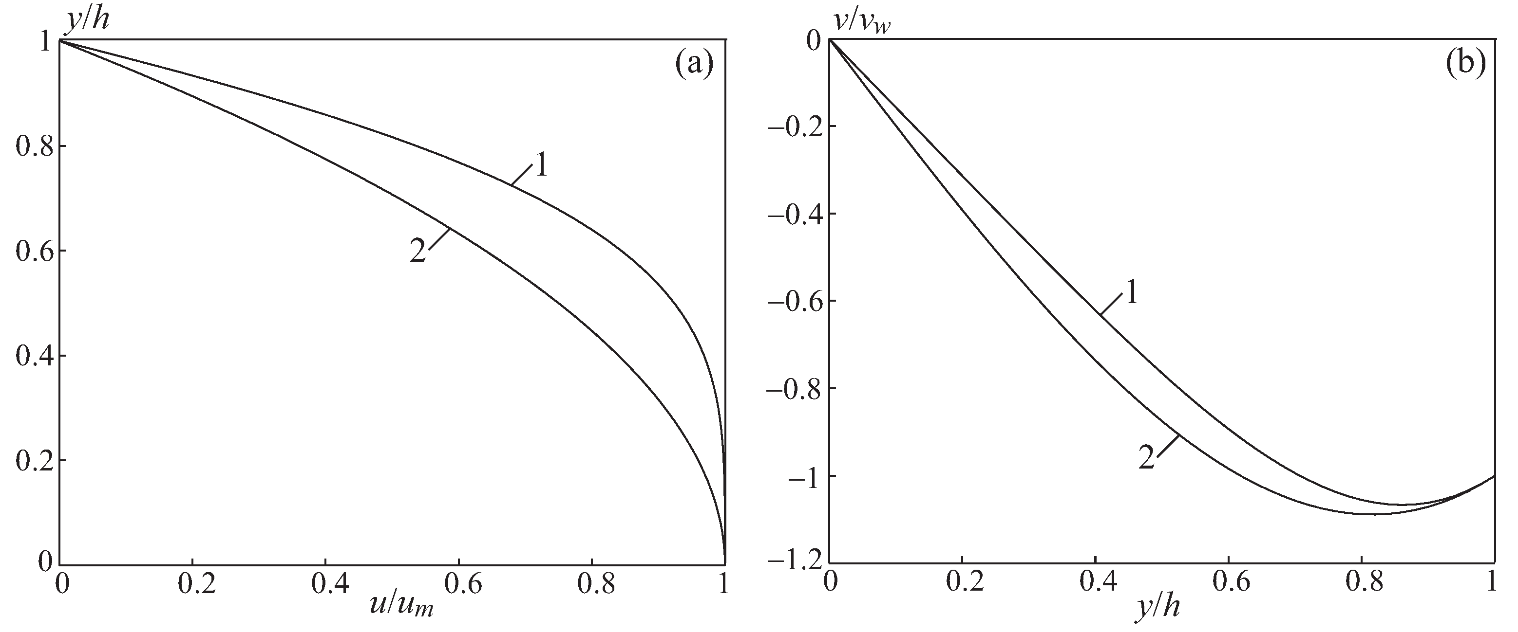
The influence of viscous effects on the flow structure in a channel with double-sided injection manifests itself mainly in the axial region, changing the fullness of the axial velocity profile (
Figure 3). In a circular channel, as the injection intensity increases, the axial velocity profile becomes less filled and tends to a cosine profile (
1) at
. The radial velocity profiles differ relatively little from each other in a wide range of injection velocities. The maximum radial velocity is located at some distance from the channel wall and exceeds the injection velocity.
Particles are non-deformable spheres of the same diameter; their collisions and their effect on the fluid are neglected. In the model of interaction between a particle and a carrier flow, the drag force and gravity force are taken into account. The drag coefficient of a particle is found from the Stokes law.
The appearance of body forces complicates the problem, since the flow becomes three-dimensional. In this case, the flow parameters in the radial plane of the channel do not depend on the axial coordinate
x (
Figure 4).
3. Governing Equations
In the discrete-trajectory approach, the equations describing the motion of a particle are written in Lagrangian variables and integrated along the trajectories of individual particles in a known (computed in advance) fluidfield.
The Equation describing the translational motion of a spherical particle has the form
where
is particle mass,
is particle midsection area,
v and
are fluid velocity and particle velocity, respectively. The term
in Equation (
2) includes forces of different nature, but different from the drag force, the account or disregard of which depends on the specific problem (for example, the gravity force is
). The drag coefficient is represented as
The function
takes into account the correction for the inertia of the particle. The Reynolds number in the relative motion of a particle and fluid is found by the formula
where
is particle radius.
A kinematic relation is added to Equation (
2), which makes it possible to calculate the radius vector of the particle’s center of mass
The temperature of a particle affects its motion through a correction to the drag coefficient. In many flow regimes, such a correction is small and is not taken into account.
Equations (
2) and (
3) are integrated along the particle trajectory and require the initial conditions (the coordinates and translational velocity of the particle at time
). The fluid velocity is calculated at the points lying on the particle trajectory,
.
4. Transformation of Coordinates
The motion of the particle is described in the Cartesian coordinate system. The Equations describing the motion of a particle have the form
Here,
. The functions
and
in (
1) are found from the relations
Equations (
4)–(
6) are supplemented with kinematic relations that allow calculating the coordinates of the particle
At the initial time
the particle is on the channel wall, therefore
The particle is injected from the wall along the normal to the surface, which gives
Here, and are the initial coordinate and initial velocity of the particle in the cylindrical coordinates (angle and velocity on the injection surface), and and .
The motion of a particle in a channel is determined by the Stokes and modified Froude numbers
where
g is gravitational acceleration.
5. Qualitative Analysis
The radial structure of a two-phase flow in a channel is determined by the system of Equations (
4)–(
9) and the corresponding initial conditions. Qualitative methods for the analysis of dynamical systems make it possible to systematize and generalize the solutions of the problem under various initial conditions and dimensionless parameters.
5.1. Zone of Gradient Flow
Near the channel centerline (
, in practice for
) functions are replaced by linear relations
For small radii, the radial velocity gradient is equal to and does not depend on the radial coordinate.
In the gradient flow zone, the system of Equations (
4)–(
9) becomes linear
The parameter Sf is the product of the Stokes number and the Froude number ().
Equations (
10)–(
12) are integrated independently of each other. A new variable is introduced
Then, Equations (
11) and (
12), describing the motion of a particle in the cross section of the channel, take the form
At the initial time .
Equations (
13) and (
14) have the same form and are independent of each other. The introduction of a new variable makes it possible to eliminate the dependence on the Stokes and Froude numbers (parameter Sf). In the coordinate system
, the flow in the gradient zone is axisymmetric and does not depend on body forces.
The characteristic equation for Equations (
13) and (
14) has the form
Solving a quadratic equation, find its roots
The roots of the characteristic equation show that there is a critical Stokes number , which determines the change in qualitatively different two-phase flow regimes. For , the particle does not cross the channel centerline (particle trajectories do not qualitatively differ from streamlines). For there is an intersection of the particle trajectory with the channel centerline.
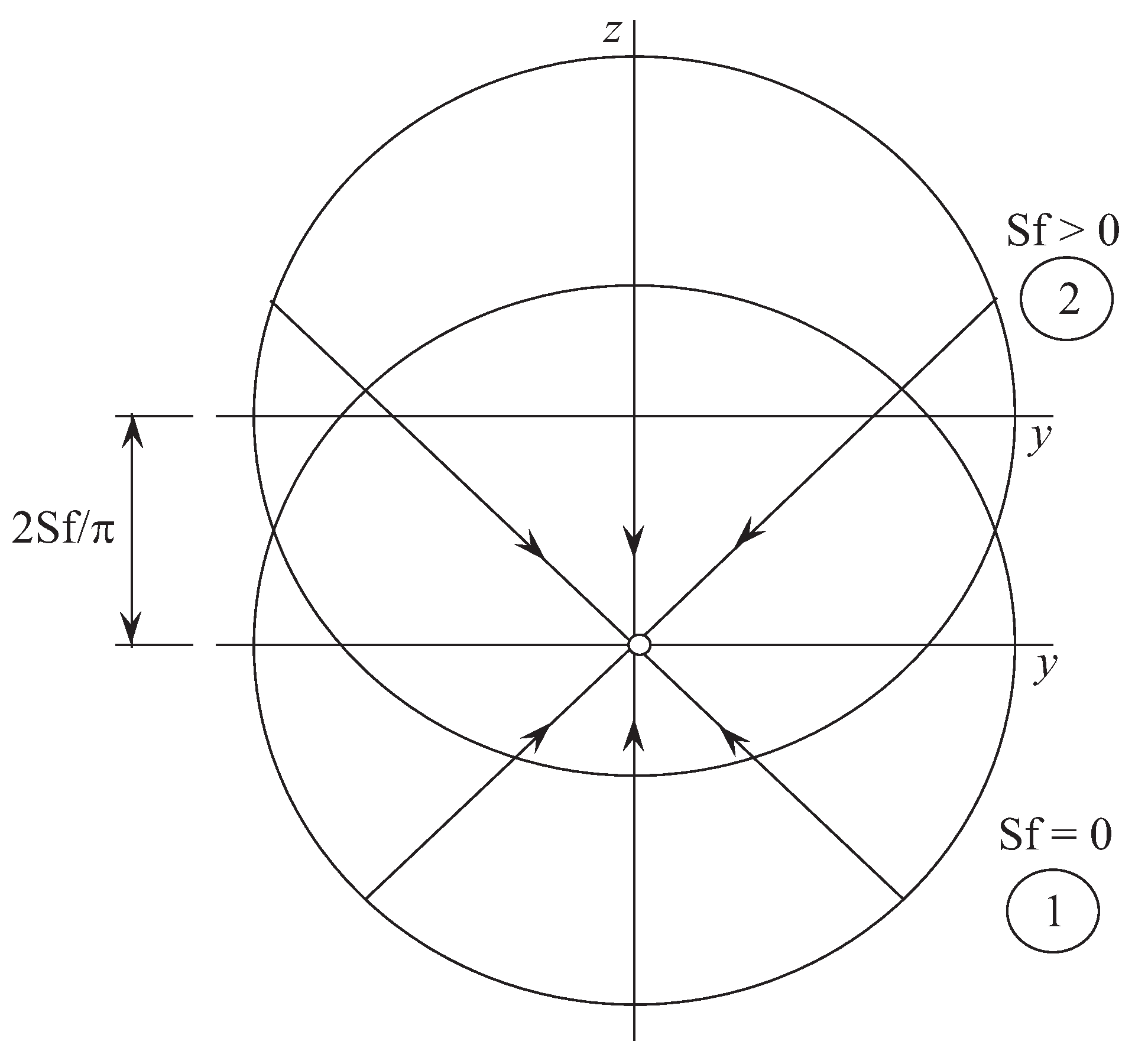
The form of particle trajectories on the plane (
) with an arbitrary parameter Sf is obtained from the special case corresponding to
. Particle trajectories are straight lines if the initial velocity vector of the particle at the boundary of the gradient zone is directed to a singular point located at the origin of the coordinate system (
Figure 5), which requires that the condition
Index 0 refers to the coordinates and initial velocity of the particle at the boundary of the gradient zone.
The particle trajectories obtained from the solution of Equations (
13) and (
14), under the specified condition and any Stokes number, are straight lines directed from the initial point on the injection surface to the singular point at the center of the channel. The oscillatory motion in the neighborhood of the singular point, which occurs at
, is along this straight line.
From a physical point of view, a singular point is a projection of the corresponding asymptote of the particle trajectories in the longitudinal section of the channel onto the radial plane. The singular point characterizes the limiting state of the particle at an unlimited time of its motion. The type of singular point depends on the Stokes number and its critical value.
At the particle trajectories monotonically approach the singular point (stable node). Particle trajectories are similar to streamlines. At , an oscillatory regime (with damping) of particle motion along a straight line relative to a singular point (stable focus) is observed. Under these conditions, a specific flow zone is formed in the channel with its characteristic counter-oscillatory motion of particles. As the Stokes number increases, this zone expands. Since the concentration of particles in this zone increases, and the probability of their collision increases, to study the flow region with counter-oscillatory motion of particles, more advanced models are required, including, in particular, the effects of interaction of particles and coupling effects.
In the absence of body forces (
), the singular point is at the center of the channel (the flow is axisymmetric). In the presence of body forces, the singular point is displaced in the direction of the vector of these forces. Approximately at
, the singular point is in the region of the gradient fluid flow. The particle trajectories in the radial section of the channel, as in the case of
, are still straight lines and are directed to a singular point, the type of which does not change within the gradient zone. The transition to the original coordinate system is graphically carried out by its shift along the
z axis by
(
Figure 5).
5.2. General Case
In the range
, Equations (
4)–(
9) describing particle motion are non-linear, which complicates their analysis and leads to the need to use numerical methods of analysis.
The gradient zone occupies the central, but smaller in terms of cross-sectional area, part of the channel. Outside this zone, the analysis is carried out on the basis of the original model described by Equations (
10)–(
12).
With the accepted direction of the gravity vector, the coordinates of singular points are found from the conditions
Singular solution points exist only on the z axis in the lower part of the channel.
For small radii (for
), an approximate relation for the singular point coordinate is obtained, which is valid for the gradient flow zone
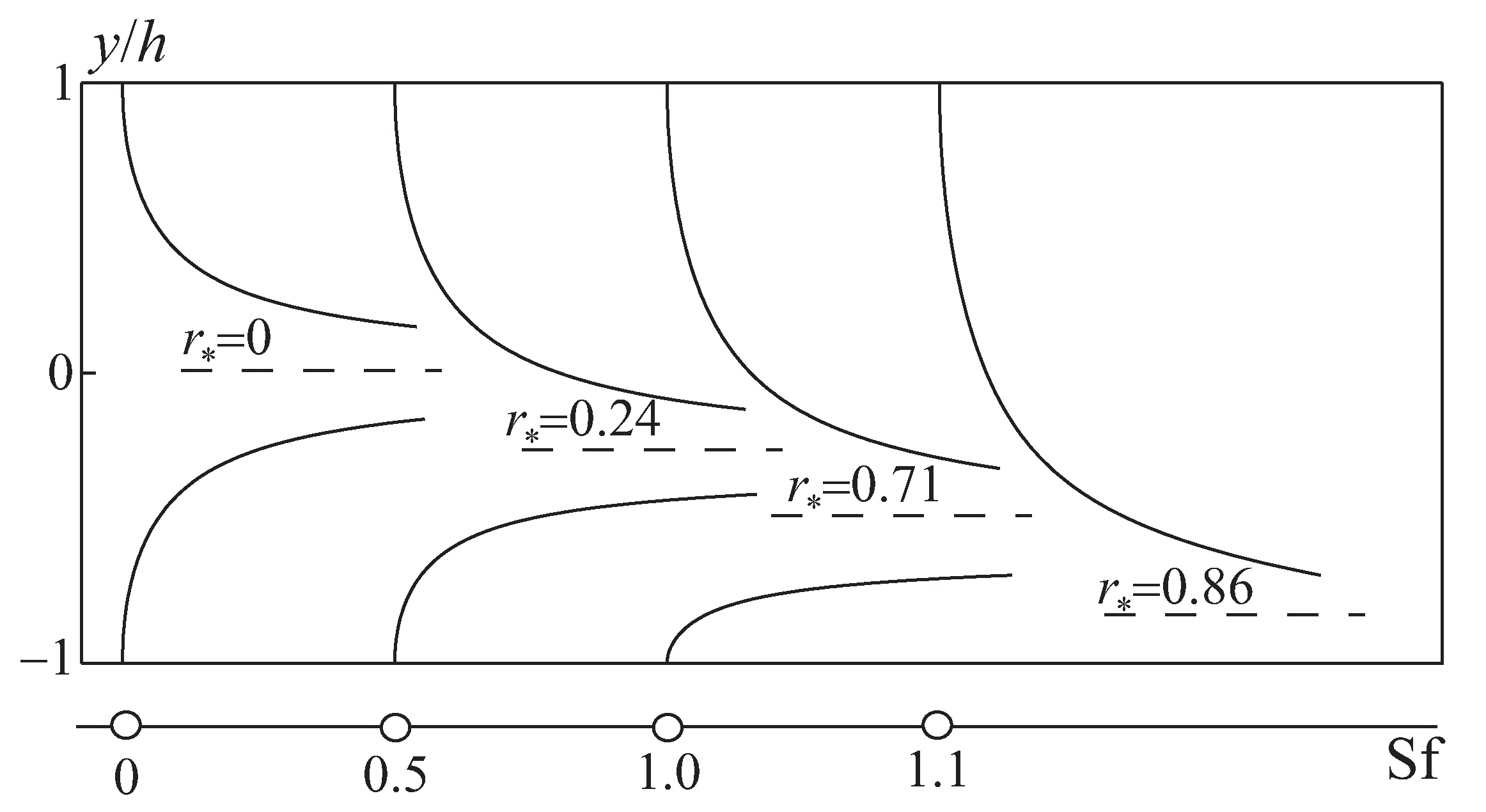
The dependence of the radial coordinate of the singular point
on the parameter Sf is shown in
Figure 6. Line 1 corresponds to the numerical solution, and line 2 corresponds to an approximate relation valid for the gradient zone of the flow.
For , there is one singular point, which is located at the origin of the coordinate system. As Sf increases, the singular point moves along line 1 obtained by the numerical solution. For small r and Sf, line 1 is approximated with good accuracy by line 2. The position of the outer boundaries of the gradient zone is found at , which takes place at .
For , the second singular point appears at (on the injection surface). As Sf increases further, the singular points approach each other (along line 1). For and these singular points merge and disappear. For , there are no singular points.
A connection between the presence and position of singular points on the phase plane and the kinematic structure of a two-phase flow in a channel is analyzed. On the phase plane, at the origin of the coordinate system , there is a single singular point of the node type (particles do not cross the channel centerline) or focus (particles cross the channel centerline) depending on the Stokes number.
When body forces are taken into account, the singular point is displaced from the origin of the coordinate system down along the
z axis. Changes in the structure of a two-phase flow in the longitudinal section of the channel are schematically shown in
Figure 7 (at
). For each Froude number, two trajectories of particles injected from the upper (
) and lower (
) surfaces of the channel are presented.
As the Froude number increases, the asymptote of the axial (along the x axis) particle trajectories, defined as , shifts downward. At the second singular point appears (such as a saddle). This state characterizes a new quality of the system, when the drag force acting on the particle from the side of the fluid at the bottom of the channel are balanced by the mass force in opposite direction. This state is dynamically unstable, and with a slight increase in the initial velocity of the particles, they are carried away into the flow. At , which corresponds to the extreme value of the radial fluid velocity in the channel at , both singular points merge. In this case, the particles from the upper half of the channel reach the asymptote of the trajectories (), while the particles on its lower side are held by body forces. The zone free from particles of the corresponding size that appeared at reaches its maximum size. For there are no singular points. This leads to a new qualitative change in the flow regimes when the asymptote of the trajectories and the zone without particles disappear. Particles in the lower half of the channel cannot leave the blowing surface, and particles leaving the upper half of the channel also fall here (given sufficient time of motion). A further increase in the Stokes and Froude numbers (parameter Sf) does not cause qualitative changes in the flow.
6. Parameter Expansion Method
A modeling of two-phase flows in channels with fluid injection is analyzed with the parameter expansion method.
6.1. Velocity of Non-Equilibrium Motion
The motion of a Stokes particle of variable size, taking into account the body forces, is described by Equation (
2), which is written in a dimensionless form
where
,
. Index 0 refers to the start time.
The general solution of Equation (
15), which is a linear ordinary differential Equation of the 1st order, is presented as the sum of the general solution of the uniform equation and a partial solution of the non-uniform Equation,
. The general solution of the uniform equation has the form
To find a partial solution of non-uniform equation, the method of expansion into a series in terms of the parameter is used
Restricting the expansion to terms of the first order of smallness, the solution of Equation (
15) takes the form
The relation (
16) shows that at
the two-phase flow tends to equilibrium (
). For
and
, flow reaches equilibrium state,
. At the final stage of evolution, the particles also come into a state of dynamic equilibrium with the fluid. For
, a solution for a particle of constant size is obtained (
).
The particle coordinates are found by resolving the kinematic relation
Integration of Equation (
17) over time from 0 to
t, for
gives
Since the time in the relation (
18) enters the term with the Stokes number as a factor, and the role of the exponential term decreases with decreasing Stokes number, the time of the equilibrium phase motion is used as the time.
The integration constants,
and
, are determined from the initial conditions. At time
, the particle is on the channel wall, therefore
where
is the parameter of the initial velocity non-equilibrium of the phases.
The obtained solution is linear with respect to the Stokes number and satisfactorily describes the particle trajectories in short channels. For it qualitatively incorrectly reflects the behavior of the particle velocity.
Let us assume that at
, where
is the burning time of a particle, the change in particle size is described by the Equation
For
, which corresponds to the theoretical model of droplet combustion, the particle velocity is found from the relation
The motion of a particle of variable size is determined by the parameter
, which is equal to the ratio of the time the particle stays in the channel
and the burning time of the particle
. The parameter characterizing the combustion of aluminum is represented as
As H increases, the conditions for particle combustion in the channel improve. For the particle burns on the channel surface, and for the particle does not burn.
The Stokes number characterizes the velocity non-equilibrium of the phases. For the particle is completely entrained by the fluid, while for its motion occurs independently of the fluid (for example, under the action of body forces). In the intermediate region, as the Stokes number increases, the velocity lag of the particle relative to the fluid increases.
At , all parameters, excluding the combustion parameter H, become negligible, and a equilibrium two-phase flow with burning particles is characterized only by the parameter H.
6.2. Domain of Applicability of the Solution
The ratio (
16) is transformed to the following form
The first term in the right side (
19) determines the influence of the initial conditions, the second term is the mass forces, and the third term is the flow gradient. The criterion for the admissibility of the expansion of the particle velocity into a series in terms of the parameter is the condition for the smallness of the degree of velocity non-equilibrium of the phases
In this case, the smallness of the Stokes number is not required. For example, for a gradientless flow, the obtained relations are exact for any Stokes number.
The equilibrium conditions correspond to the case
. There is no influence of the initial conditions on the further motion of the particle, and the equilibrium initial velocity is found from the relation
The intensity of attenuation of the influence of the initial state of the particle is determined by the Stokes number, and when a particle of variable mass moves, the influence of the initial conditions depends on its size.
Body forces affect the rate of non-equilibrium motion of phases through the Froude criterion. The influence of body forces increases with increasing Stokes number, decreases as decreases, and manifests itself to the greatest extent in low-velocity regions.
In a gradientless flow , and there is no influence of the gas-dynamic factor. For the influence of the gas-dynamic factor increases as the Stokes number increases and decreases along with . The value of the derivative depends on the geometric shape of the channel and reaches its maximum value in narrow channels and in places where the flow turns.
Taking the injection speed as the characteristic speed, and the ratio of the free volume of the combustion chamber to the fuel combustion area (
,
) as the characteristic size, the Stokes number is written as
where
W and
S are volume and cross-sectional area of combustion chamber. When the propellant burns out, the parameter
decreases, which leads to a decrease in the degree of velocity non-equilibrium of the phases due to the weakening of the influence of the gas-dynamic factor.
6.3. Solution for Strong Injection
In channels with strong injection (
), the relations (
16) and (
18) are presented in the analytical form. The particle coordinates are found from the relations
The time in the equilibrium motion of the phases is
The constants of integration are found from the initial conditions
Up to the terms
, the following relations, which give the velocities and coordinates of the particle at an arbitrary moment of time, are valid
The velocity distributions of the dispersed phase in the channel are shown in
Figure 8 and
Figure 9 (results are normalized to the maximum velocity in the cross section,
, and injection velocity,
). Lines 1 correspond to the carrier flow, and lines 2–5 correspond to particles of various sizes. The influence of the initial non-equilibrium flow leads to deformation of the radial velocity profile of the dispersed phase near the injection surface. In general, the distributions of the radial velocity differ relatively little from each other in a wide range of problem parameters.
7. Numerical Results
The results of numerical simulation are shown in
Figure 10 and
Figure 11 for particles of different sizes. The Froude number is 1, and the Sf parameter is varied by appropriately changing the Stokes number. For each Stokes number, two trajectories for
(lower and upper walls of the channel) are given, and the position of the singular point (if it exists) is indicated. The prime corresponds to the particles injected from the bottom of the channel. The results are obtained at different initial particle velocity.
It follows from the calculations that for particles injected from the upper part of the channel, a change in the initial velocity has practically no effect on the shape of the phase trajectories (
Figure 11a). Particles injected from the lower half of the channel turn out to be more sensitive to changes in the initial conditions (
Figure 11b).
For , the singular point shifts slightly down along the z axis, and its type is a stable node. When Sf is increased to 0.5, the singular point type changes from node to focus. Accordingly, the type of phase trajectories also changes, which in the vicinity of the singular point acquire a damped oscillatory character. An increase in the initial particle velocity slightly affects the results.
For , the flow structure in the channel becomes more complicated. Due to the fact that the singular point is close enough to the lower surface of the channel, and the amplitude of particle oscillations near this point is significant, conditions arise for them to fall out of the flow. Particles located at the bottom of the channel at the initial moment at cannot leave the injection surface. However, an increase in the initial velocity module violates this dynamic equilibrium and leads to separation particles from the injection surface of the channel and their involvement in the flow, followed by asymptotic approximation to the corresponding singular point.
For there are no singular points on the phase plane. Particles leaving the upper half of the channel eventually reach the lower surface, from which they cannot leave at zero initial velocity. An increase in the initial velocity of the particles leads to a temporary removal of particles from the lower part of the channel into the flow, followed by their fallout onto the same surface.
The trajectories of particles emerging from different points on the injection surface of the channel are shown in
Figure 12 (for
).
At , a specific zone of counter-oscillatory motion of particles is formed in the vicinity of the singular point. As the Sf parameter increases to 1, this zone expands, deforms, and captures the lower part of the channel. The change in the structure of this flow zone is accompanied by the precipitation of some particles from the flow onto the channel surface.
Depending on the Stokes number, the singular point is either a node or a focus. Outside the gradient zone, the critical Stokes number, which characterizes the change in the type of singular point, gradually increases as the singular point moves away from the center of the channel.
For , a second saddle-type singular point appears on the channel surface. The presence of two singular points, their relative proximity to each other and to the channel walls leads to the formation of a complex structure of a two-phase flow. New effects arise, in particular, the precipitation of particles from the flow onto the channel walls and the impossibility of their detachment from the injection surface. This is due to the fact that the oppositely directed drag and mass forces acting on the particles are approximately equal. As a consequence, under these conditions, the influence of secondary factors increases, for example, the initial velocity of particles on the injection surface.
8. Conclusions
A qualitative analysis of the trajectories of an individual particle in a channel with fluid injection from walls has been carried out. The computational domain is divided into a zone of gradient flow, in which the linearized equations of particle motion are applied, and a near-wall zone, in which an approximate solution of the problem is obtained. The results of the qualitative analysis are compared with numerical calculations, on the basis of which the singular points of the individual particle trajectory are found for various Stokes and Froude numbers.
The distributions of the dispersed phase parameters were obtained up to terms linear with respect to the Stokes number. Factors influencing the rate of non-equilibrium motion of phases are identified, and the domains of applicability of the obtained solution are investigated. The velocity and concentration distributions of particles in channels with strong injection are derived.


