
Environmental Impact of Demolishing a Steel Structure Design for Disassembly

Abstract
1. Introduction
1.1. Design for Disassembly
- designing for reduced consumption and environmental impact of raw materials, components and energy;
- designing for the use of cleaner production techniques and technologies;
- designing for reduction in quantity and harmfulness of post-production waste;
- design for recovery and use of post-consumer waste.
1.2. Circular Economy in Steel Constructions
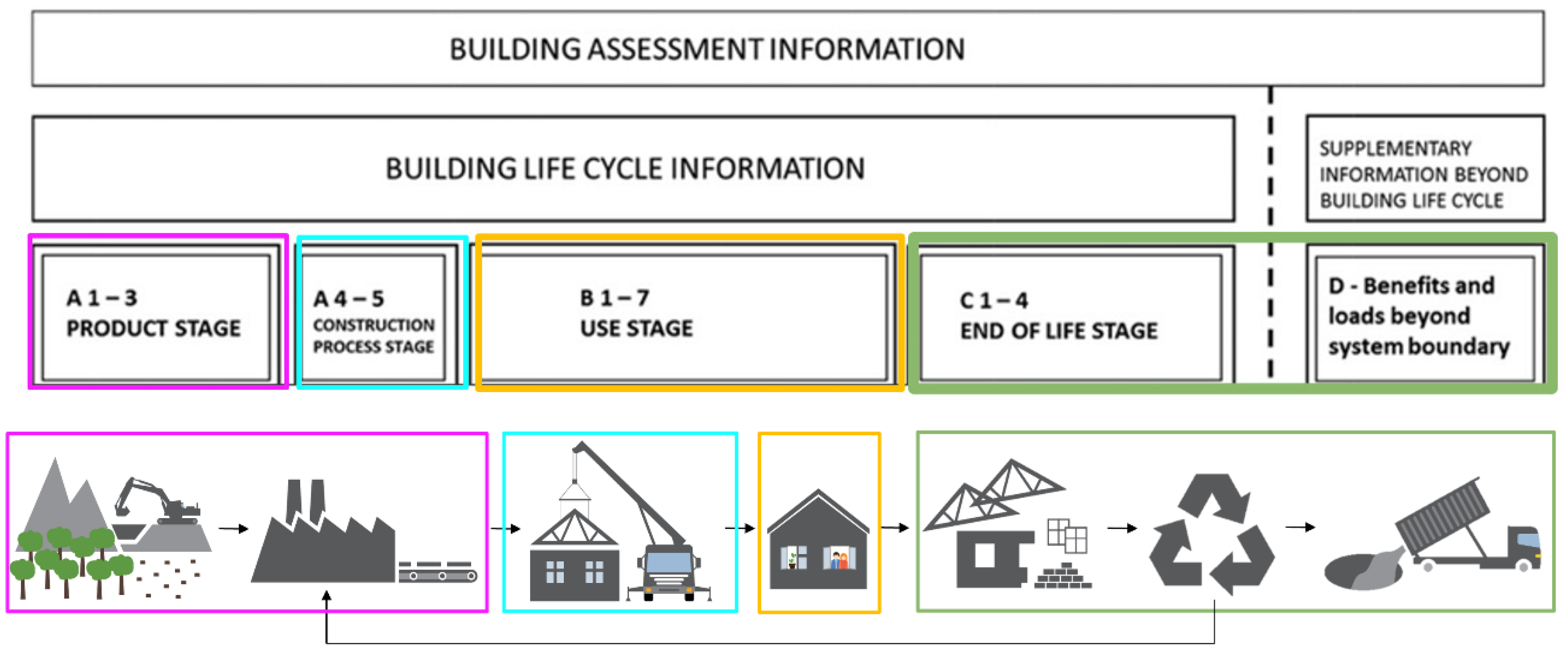
1.3. Life Cycle Assessment of Buildings
2. Materials and Methods
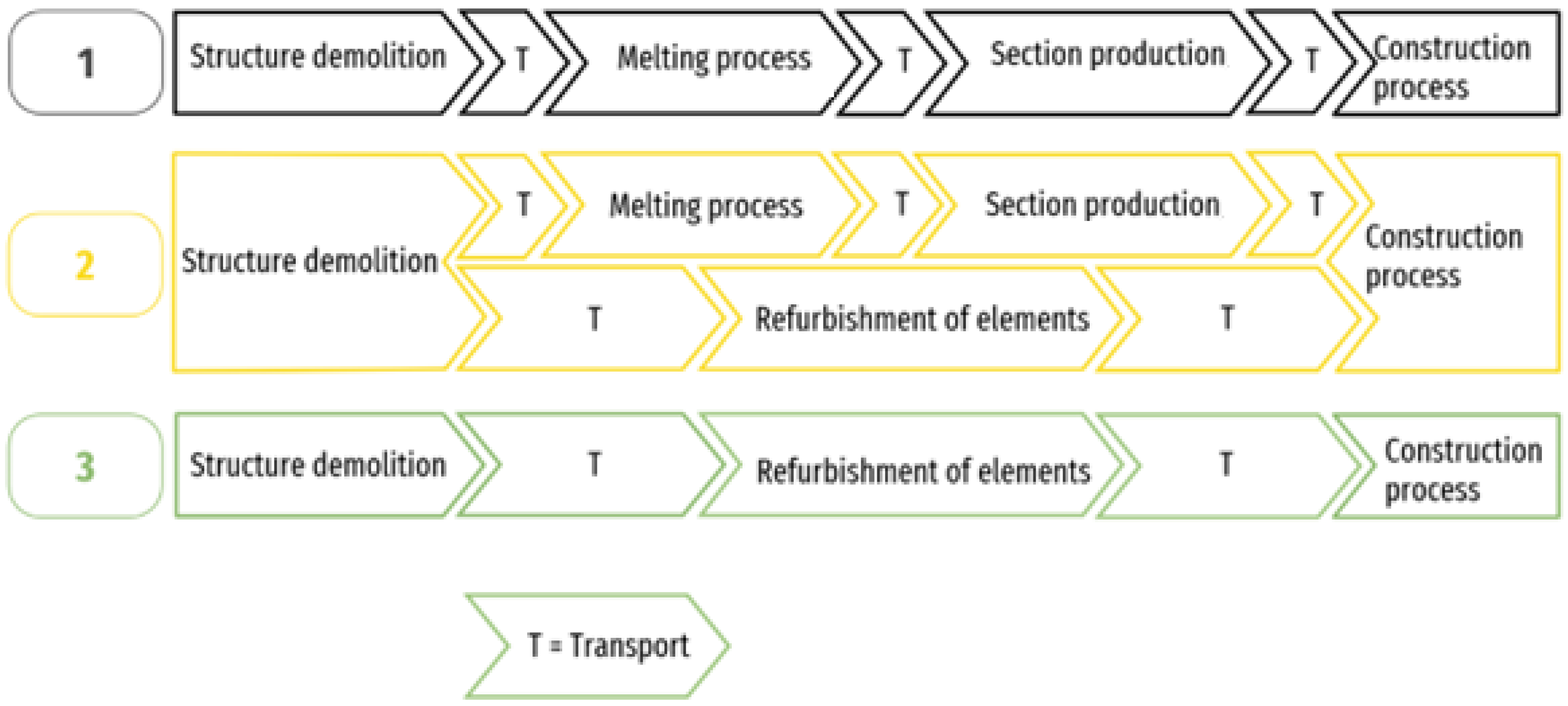
2.1. Goal and Scope, System Boundaries, Scenario Assumptions
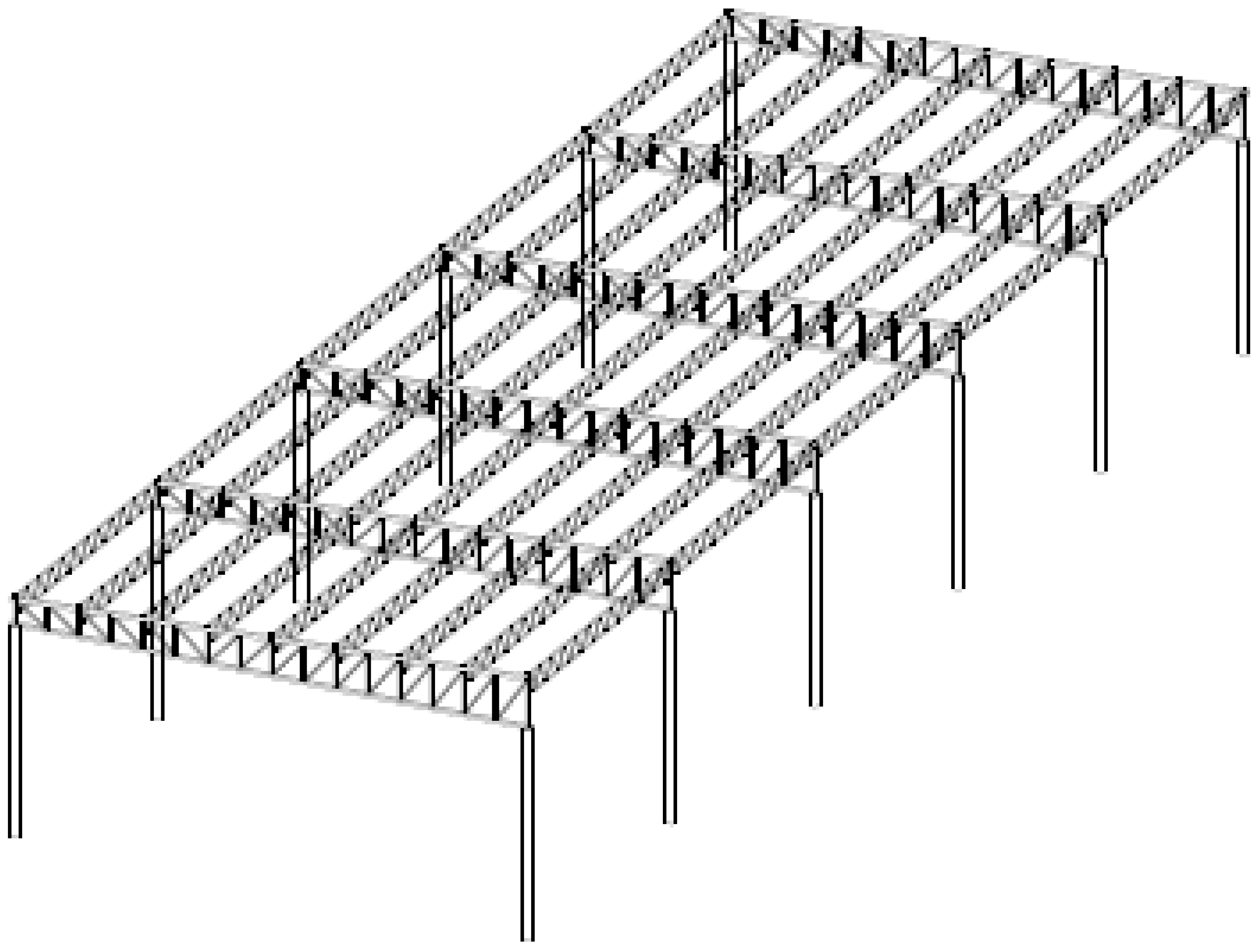
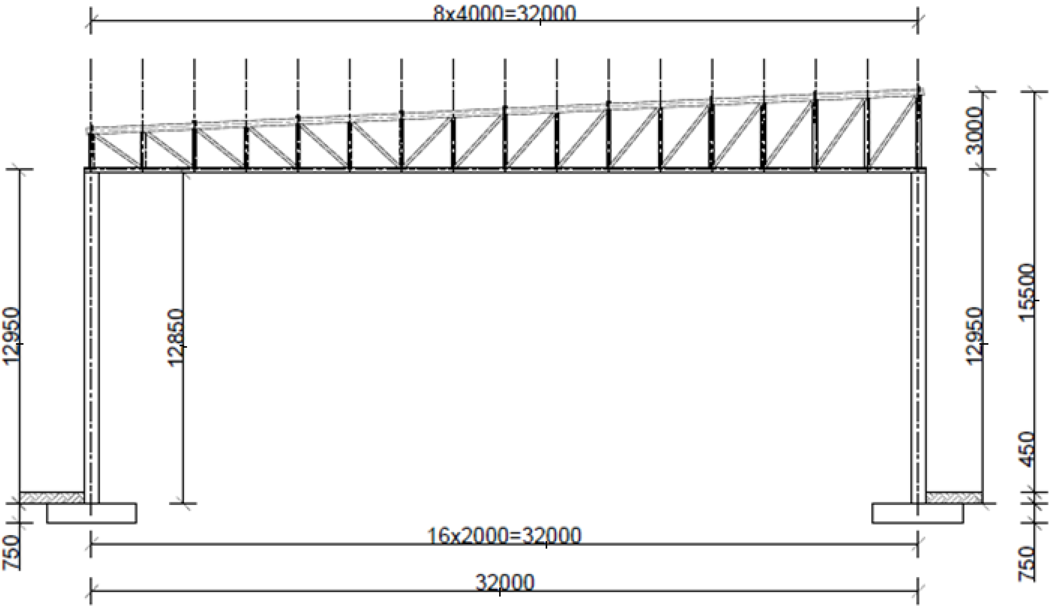
2.2. Subject of the Study and Functional Unit
2.3. LCIA (Life Cycle Inventory Analysis) Methodology
2.4. Implementation of LCA
3. Results
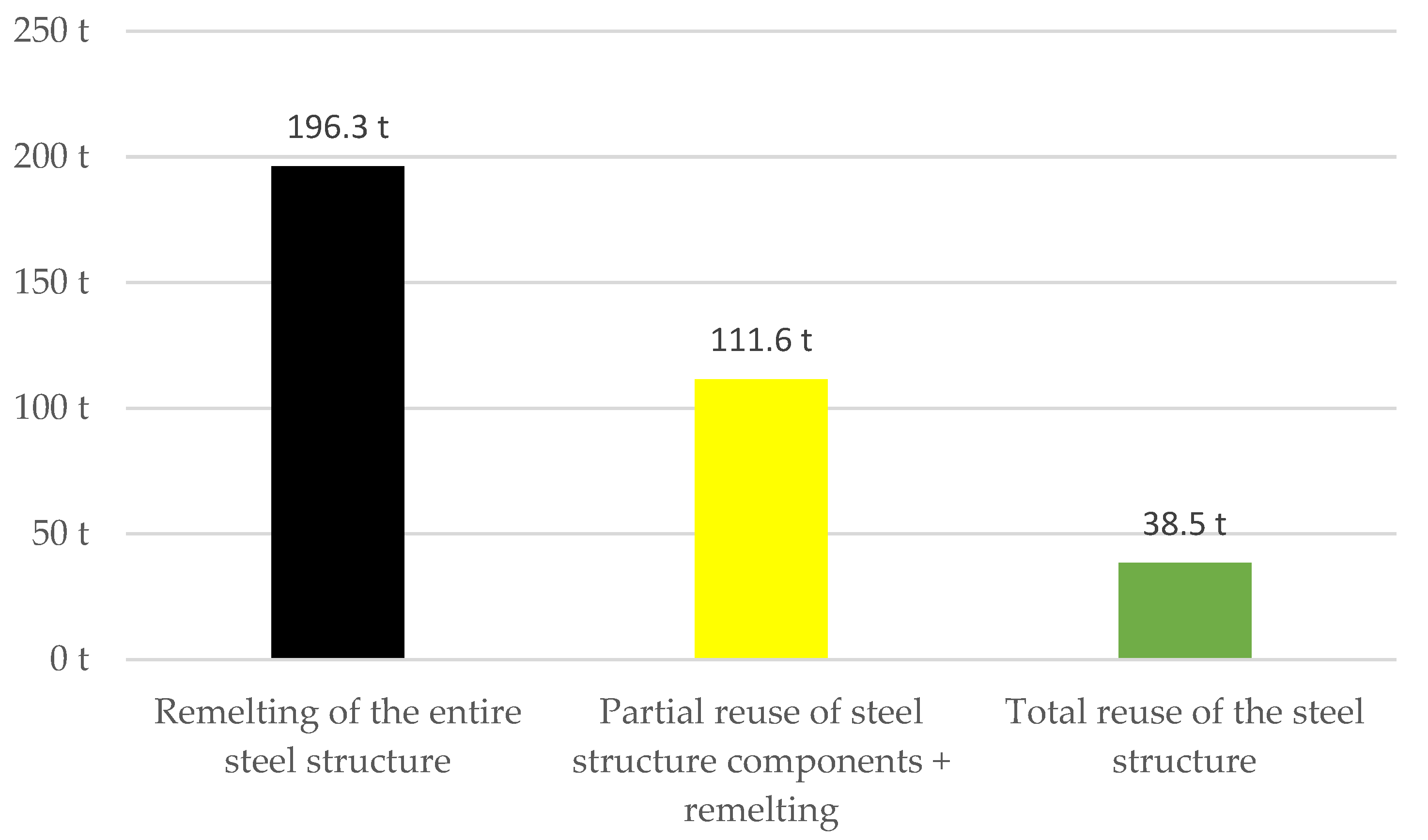
3.1. Global Warming Potential
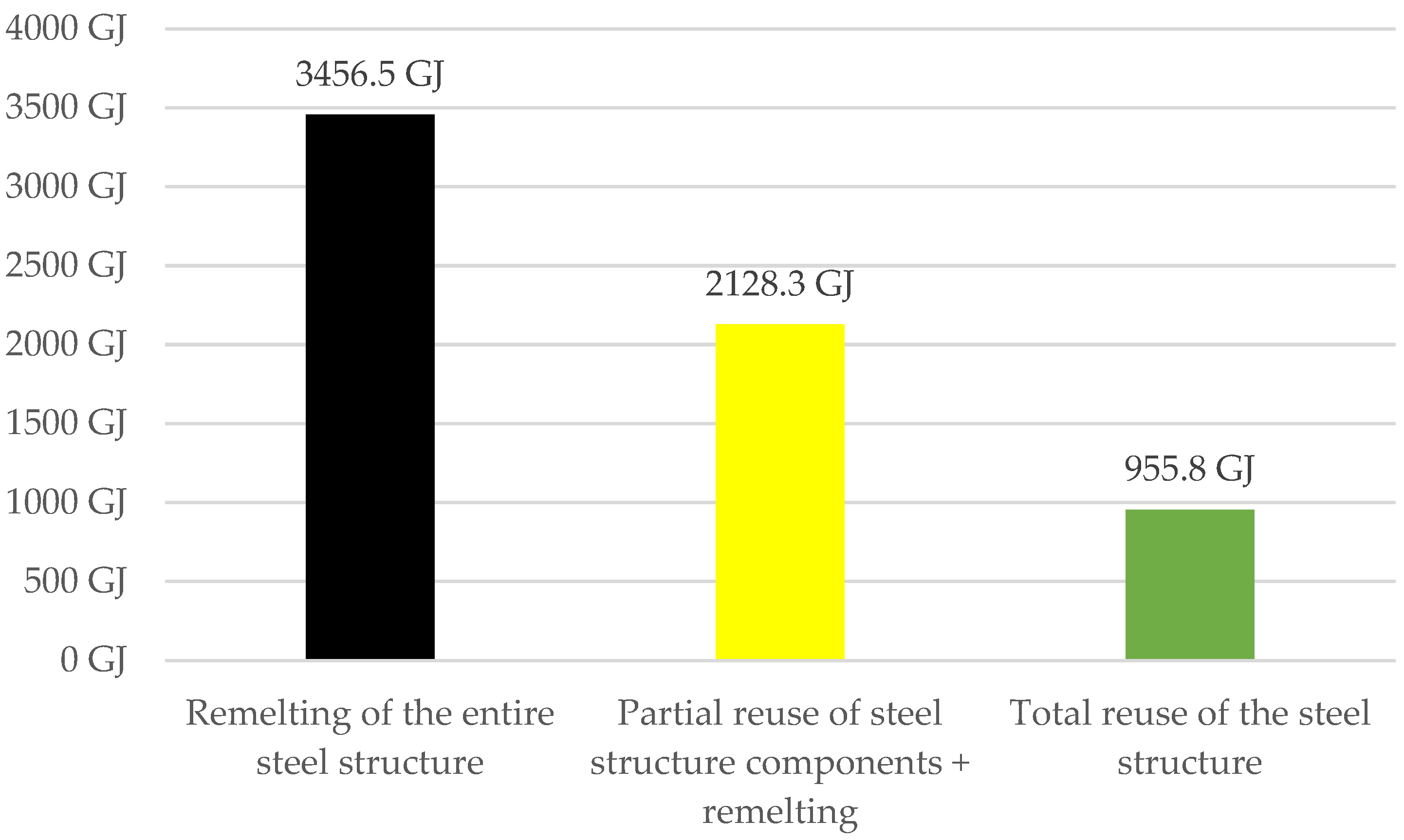
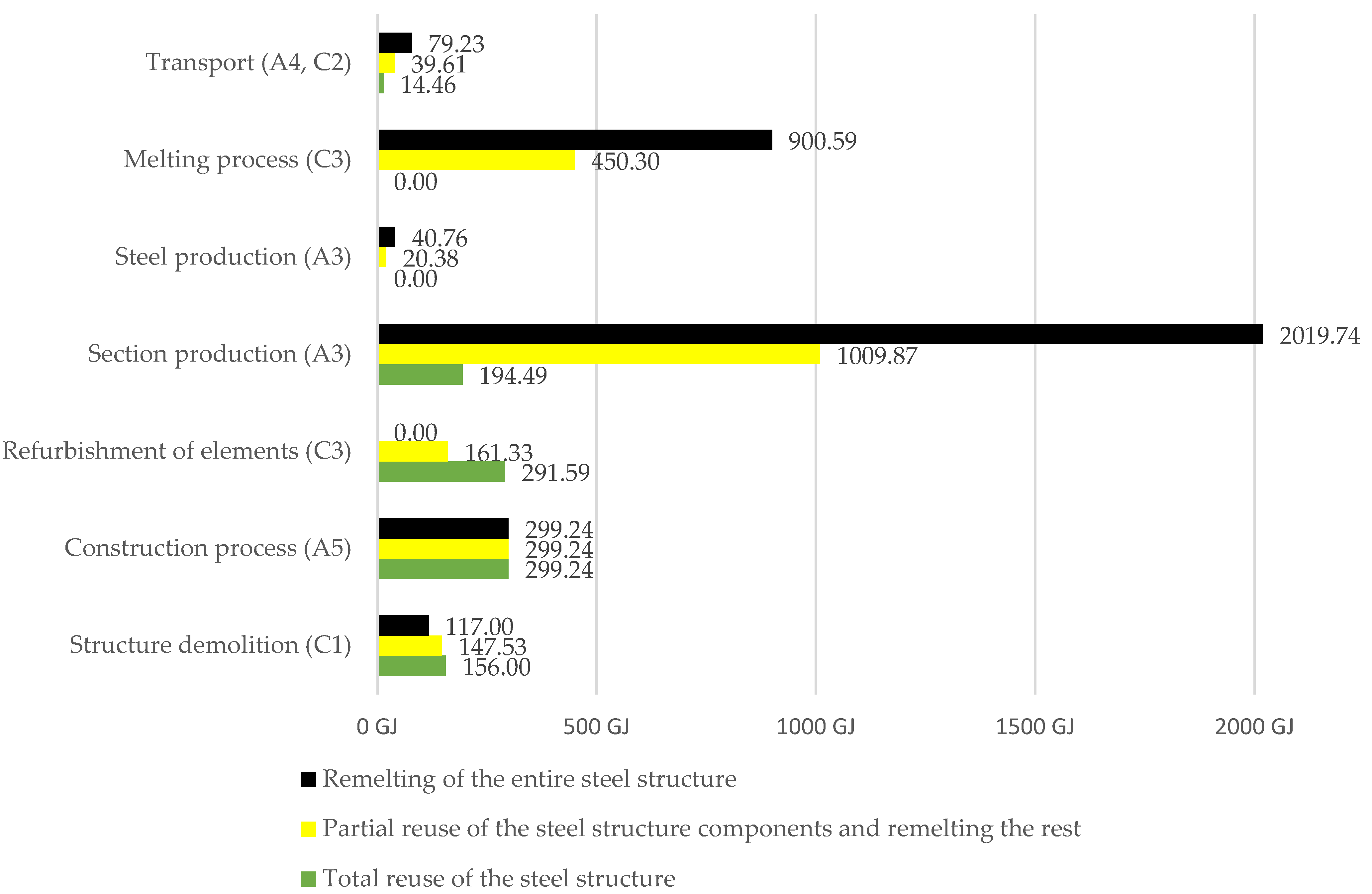
3.2. Primary Energy Use
4. Discussion
4.1. Comparison with Other Studies
4.1.1. Studies in Which the Individual Processes of the EoL Phase Are considered
4.1.2. Research on LCA of Steel
4.2. Limitations and Future Work
5. Conclusions
Author Contributions
Funding
Institutional Review Board Statement
Informed Consent Statement
Acknowledgments
Conflicts of Interest
References
- Global Status Report for Buildings and Construction. Towards a Zero-Emissions, Efficient and Resilient Buildings and Construction Sector. 2021. Available online: https://www.unep.org/resources/report/2021-global-status-report-buildings-and-construction (accessed on 22 August 2022).
- Statistics | Eurostat. Available online: https://ec.europa.eu/eurostat/databrowser/view/CEI_WM040/default/bar?category=cei.cei_wm (accessed on 28 July 2022).
- Cutieru, A. A Guide to Design for Disassembly | ArchDaily. Available online: https://www.archdaily.com/943366/a-guide-to-design-for-disassembly (accessed on 19 July 2022).
- Baran, J. Projektowanie Pod Kątem Czystszej Produkcji Jako Podejście Projektowe w Gospodarce o Obiegu Zamkniętym-Ujęcie Koncepcyjne Oraz Studium Przypadku. In Innowacje w Zarządzaniu i Inżynierii Produkcji; Knosala, R., Ed.; Oficyna Wydawnicza Polskiego Towarzystwa Zarządzania Produkcją: Opole, Poland, 2018; Volume 1, pp. 379–390. [Google Scholar]
- Kanters, J. Design for Deconstruction in the Design Process: State of the Art. Buildings 2018, 8, 150. [Google Scholar] [CrossRef]
- Gorgolewski, M. Designing with reused building components: Some challenges. Build. Res. Inf. 2008, 36, 175–188. [Google Scholar] [CrossRef]
- Rios, F.C.; Chong, W.K.; Grau, D. Design for Disassembly and Deconstruction-Challenges and Opportunities. Procedia Eng. 2015, 118, 1296–1304. [Google Scholar] [CrossRef]
- European Commission. Communication From the Commission to the European Parliament, the Council, the European Economic and Social Committee and The Committee of the Regions. Closing the Loop-An EU Action Plan for the Circular Economy; European Commission: Brussels, Belgium, 2015. Available online: https://eur-lex.europa.eu/legal-content/EN/TXT/?uri=CELEX:52015DC0614 (accessed on 21 August 2022).
- ISO 20887:2000; Sustainability in Buildings and Civil Engineering Works-Design for Disassembly and Adaptability-Principles, Requirements and Guidance. ISO: Geneva, Switzerland, 2020.
- Regulation (EU) 2020/852 of the European Parliament and of the Council of 18 June 2020 on the Establishment of a Framework to Facilitate Sustainable Investment, and Amending Regulation. Available online: https://eur-lex.europa.eu/legal-content/EN/TXT/?uri=celex:32020R0852 (accessed on 21 August 2022).
- Proposal for a Directive of the European Parliament and of the Council Amending Directive 2013/34/EU, Directive 2004/109/EC, Directive 2006/43/EC and Regulation (EU) No 537/2014, as Regards Corporate Sustainability Reporting. Unformal Publication. 2021.
- New Rules on Corporate Sustainability Reporting: Provisional Political Agreement between the Council and the European Parliament-Consilium. Available online: https://www.consilium.europa.eu/en/press/press-releases/2022/06/21/new-rules-on-sustainability-disclosure-provisional-agreement-between-council-and-european-parliament/ (accessed on 28 July 2022).
- Biernacki, P. Taksonomia CSRD. Przyszłość Raportowania ESG. Unformal Publication.
- World Steel Association. Steel in the Circular Economy. A Life Cycle Perspective. World Steel Association: Brussels, Belgium, 2015; ISBN 978-2-930069-80-7. [Google Scholar]
- EN 15978:2011-Sustainability of Construction Works-Assessment of Environmental Performance of. Available online: https://standards.iteh.ai/catalog/standards/cen/62c22cef-5666-4719-91f9-c21cb6aa0ab3/en-15978-2011 (accessed on 5 August 2022).
- Birgisdottir, H.; Rasmussen, F.N. Introduction to LCA of Buildings, 1st ed.; Trafik-og Byggestyrelsen; Publisher Danish Transport and Construction Agency: København S, Denmark, 2016. [Google Scholar]
- Vilches, A.; Garcia-Martinez, A.; Sanchez-Montañes, B. Life cycle assessment (LCA) of building refurbishment: A literature review. Energy Build 2016, 135, 286–301. [Google Scholar] [CrossRef]
- Hong, J.K.; Shen, G.Q.P.; Feng, Y.; Lau, W.S.-T.; Mao, C. Greenhouse gas emissions during the construction phase of a building: A case study in China. J. Clean. Prod. 2015, 103, 249–259. [Google Scholar] [CrossRef]
- Buchanan, A.; John, S.; Love, S. Life Cycle Assessment and Carbon Footprint of Multi-Storey Timber Buildings Compared with Steel and Concrete Buildings. N. Z. J. For. 2013, 57, 9–18. [Google Scholar]
- Wralsen, B.; Skaar, C. Life cycle assessment of an ambitious renovation of a Norwegian apartment building to nZEB standard. Energy Build. 2018, 177, 197–206. [Google Scholar] [CrossRef]
- Ivanica, R.; Risse, M.; Weber-Blaschke, G.; Richter, K. Development of a life cycle inventory database and life cycle impact assessment of the building demolition stage: A case study in Germany. J. Clean. Prod. 2022, 338, 130631. [Google Scholar] [CrossRef]
- Broniewicz, M. Refurbishment, Strengthening and Durability of Existing Building Structures. Ekon. I Sr. Econ. Environ. 2018, 4, 36–48. [Google Scholar]
- Lyu, Y.-F.; Li, G.-Q.; Cao, K.; Zhai, S.-Y.; Li, H.; Chen, C.; Wang, Y.-Z. Behavior of splice connection during transfer of vertical load in full-scale corner-supported modular building. Eng. Struct. 2021, 230, 111698. [Google Scholar] [CrossRef]
- Broniewicz, F.; Broniewicz, M. Sustainability of Steel Office Buildings. Energies 2020, 13, 3723. [Google Scholar] [CrossRef]
- Piszczatowska, M. Sports Hall Made of Hollow Sections. 2017. Master’s Thesis. Technical University of Bialystok, Bialystok, Poland.
- Hollerud, B.; Bowyer, J.; Jeff Howe, P.D.; Ed Pepke, P.D.; Kathryn Fernholz, P.D. A Review of Life Cycle Assessment Tools; Dovetail Partners Inc.: Minneapolis, MI, USA, 2017. [Google Scholar]
- Manual, G. GaBi Manual. pp. 53–54. Available online: https://www.google.com/url?sa=t&rct=j&q=&esrc=s&source=web&cd=&cad=rja&uact=8&ved=2ahUKEwjIutOlpsH6AhWSDRAIHVlzAWIQFnoECBIQAQ&url=https%3A%2F%2Fgabi.sphera.com%2Ffileadmin%2FGaBi_Manual%2FGaBi_6_manual.pdf&usg=AOvVaw3N3XyFT_R85yGjWEsCXmCw (accessed on 15 June 2022).
- Przemysłowa Wkrętarka, Pistoletowa Do Śrub M5 FD-5P Fuji Sklep Atmo. Available online: https://atmo.com.pl/pl/p/Przemyslowa-wkretarka%2C-pistoletowa-do-srub-M5/1560 (accessed on 27 July 2022).
- Liebherr Werk Biberach GmbH. Catalog Turmdrehkran 125 K. Available online: www.liebherr.com (accessed on 27 January 2022).
- Kalkulator Kosztów Eksploatacji | John Deere. Available online: https://tools.deere.com/john-deere-total-cost-of-ownership/pl_PL/ (accessed on 27 January 2022).
- Samojezdny żuraw terenowy REX 16. Available online: https://www.zbud.com.pl/index.php?page=produkty&kategoria=256 (accessed on 27 January 2022).
- P&H 5150-R Crawler Crane. Specifications. Available online: https://freecranespecs.com/P-H/5150-R (accessed on 28 July 2022).
- HDS 13/20-4 SX | Kärcher W Polsce. Available online: https://www.kaercher.com/pl/professional/urzadzenia-wysokocisnieniowe/urzadzenia-wysokocisnieniowe-z-podgrzewaniem-wody/klasa-super/hds-13-20-4-sx-10719320.html (accessed on 16 February 2022).
- Peugeot. Samochód Dla Profesjonalistów. Specyfikacja. Available online: www.peugeot.pl (accessed on 18 March 2022).
- Altrad Poland S.A. Betoniarka Wolnospadowa. Instrukcja Obsługi. 2011. Available online: https://altradpoland.pl/?page_id=36 (accessed on 15 March 2022).
- Wysokiej Mocy Grzewczy Agregat Elektryczny TEH 300-TROTEC. Available online: https://pl.trotec.com/produkty-i-uslugi/maszyny-highperformance/ogrzewanie/elektryczne-agregaty-grzewcze-serii-teh/teh-300/ (accessed on 18 February 2022).
- Kompresor ATMOS PDP 35 (Perkins) 5,0 m3/7 bar Technical Master. Available online: https://www.technicalmaster.pl/pl/p/Kompresor-ATMOS-PDP-35-Perkins-5%2C0-m7-bar/44 (accessed on 18 February 2022).
- Atlas Copco XATS 377 CD Specyfikacja & Dane Techniczne (2007–2014). Available online: https://www.lectura-specs.pl/pl/model/urzadzenia-budownictwa-nad-i-podziemnego/sprezarki-i-kompresory-powietrza-przenosne-sprezarki-i-kompresory-powietrza-wyskoprezne-elektryczne-i-spalinowe-atlas-copco/xats-377-cd-1049697#techSpecs (accessed on 18 February 2022).
- Giorgi, S.; Lavagna, M.; Campioli, A. Life Cycle Assessment of Building End of Life. In Proceedings of the 12th Italian LCA Network Conference Life Cycle Thinking in Decision-Making for Sustainability: From Public Policies to Private Businesses, Messina, Italy, 11–12 June 2018; pp. 30–38. [Google Scholar]
- Temporelli, A.; Carvalho, M.L.; Girardi, P. Life Cycle Assessment of Electric Vehicle Batteries: An Overview of Recent Literature. Energies 2020, 13, 2864. [Google Scholar] [CrossRef]
- Petrovic, B.; Myhren, J.A.; Zhang, X.; Wallhagen, M.; Eriksson, O. Life cycle assessment of a wooden single-family house in Sweden. Appl. Energy 2019, 251, 113253. [Google Scholar] [CrossRef]
- Takano, A.; Hafner, A.; Linkosalmi, L.; Ott, S.; Hughes, M.; Winter, S. Life cycle assessment of wood construction according to the normative standards. Holz Als Roh. Und. Werkst. 2015, 73, 299–312. [Google Scholar] [CrossRef]
- Kakkos, E.; Heisel, F.; Hebel, D.E.; Hischier, R. Environmental assessment of the Urban Mining and Recycling (UMAR) unit by applying the LCA framework. IOP Conf. Series Earth Environ. Sci. 2019, 225, 012043. [Google Scholar] [CrossRef]
- Dodoo, A.; Gustavsson, L. Life cycle primary energy use and carbon footprint of wood-frame conventional and passive houses with biomass-based energy supply. Appl. Energy 2013, 112, 834–842. [Google Scholar] [CrossRef]
- Gustavsson, L.; Joelsson, A.; Sathre, R. Life cycle primary energy use and carbon emission of an eight-storey wood-framed apartment building. Energy Build. 2010, 42, 230–242. [Google Scholar] [CrossRef]
- Rics.Org/Guidance RICS Professional Statement Whole Life Carbon Assessment for the Built Environment. Available online: www.rics.org (accessed on 24 August 2022).
- Strezov, L.; Herbertson, J. Life Cycle Perspective on Steel Building Materials; Principals of the Crucible Group Pty Ltd.: Mayfield West, Australia, 2006. [Google Scholar]
- Oladazimi, A.; Mansour, S.; Hosseinijou, S.A. Comparative Life Cycle Assessment of Steel and Concrete Construction Frames: A Case Study of Two Residential Buildings in Iran. Buildings 2020, 10, 54. [Google Scholar] [CrossRef]
- Kim, S.; Moon, J.-H.; Shin, Y.; Kim, G.-H.; Seo, D.-S. Life Comparative Analysis of Energy Consumption and CO2Emissions of Different Building Structural Frame Types. Sci. World J. 2013, 2013, 175702. [Google Scholar] [CrossRef] [PubMed]
- Akinade, O.O.; Oyedele, L.O.; Ajayi, S.O.; Bilal, M.; Alaka, H.A.; Owolabi, H.A.; Bello, S.A.; Jaiyeoba, B.E.; Kadiri, K.O. Design for Deconstruction (DfD): Critical success factors for diverting end-of-life waste from landfills. Waste Manag. 2017, 60, 3–13. [Google Scholar] [CrossRef] [PubMed]


| Parameter | The Scenario | Assumed Value | What It Affects | Other Possibilities | The Expected Degree to Which Volatility Affects the Result of the Analysis |
|---|---|---|---|---|---|
| Distance from the steelworks | 1, 2 | road transport 500 km | fuel consumption | e.g., road tr. 700 km; rail tr. 1000 km | low |
| Distance from the place of reuse | 2, 3 | road transport 100 km | fuel consumption | e.g., road tr. 200 km, rail tr. 300 km | low |
| Connections of steel elements | 1,2,3 | screw | maximum % recovered items possible | rivets welded | very large |
| Method of manufacturing sections | 1,2 | hot rolled | energy consumption | cold-formed welded (plated) | large |
| Method of cleaning the elements | 2,3 | sandblasting | energy and fuel consumption | manual cleaning | medium |
| Overall dimensions of the hall | 32 m × 16 m × 90 m |
| Weight of the elements | 135 t |
| Area of steel sections | 2 007 m2 |
| Joints | bolted |
| Hall area | 2 880 m2 |
| Process | Flow | Data Source | |
|---|---|---|---|
| Construction a/Demolition a | Electricity consumption | Professional screwdriver, straight, high-speed FW-5SXD-7 ATMO (1.1 kW; 85 mth b c) [28] | |
| Fuel consumption | Tower crane LIEBHERR 125K (7 L/h; 240 mth b) [29] Wheeled tractor John Deere 6215R (30 L/h; 62 mth b) [30] Mobile rough terrain crane REX 25t (16 L/h; 37 mth b) [31] Crawler crane 140t—P&H 5150-R (35 L/h; 70 mth b) [32] | ||
| Transport | Fuel consumption | GaBi: Truck, Euro 6, 26—28t—Sphera | |
| Melting of steel scrap in an electric furnace | GaBi: EAF Steel billet—Sphera | ||
| Manufacture of semi-finished products for section production | GaBi: BF Steel billet—Sphera | ||
| Manufacturing of sections on a rolling line | GaBi: Steel sections—AISI | ||
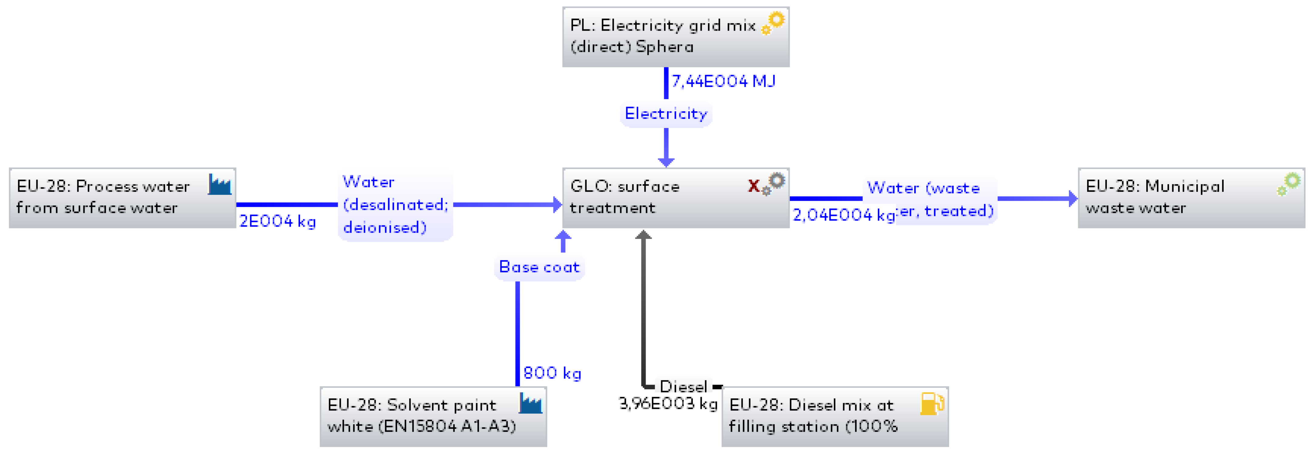
| Refurbishment of elements a | Washing of elements with pressurized water | Water use | GaBi: Process water from surface water—Sphera |
| Wastewater | GaBi: Municipal wastewater—Sphera | ||
| Electricity consumption | Pressure washer 20 MPa Karcher HDS 13/20 4SX (10 L/h; 32 mth b) [33] | ||
| Fuel consumption | Cargo Delivery Van Peugeot Boxer Furgon PRO L4H2 435 (15 L/h; 2 mth b) [34] | ||
| Sand drying | Electricity consumption | Free-fall concrete mixer 250 dm3 BWE-250k. Altrad Spomasz (1.5 kW; 106 mth b) [35] Agregat grzewczy elektryczny TEH 300 TROTEC (70 kW; 106 mth b) [36] | |
| Cleaning of elements to grade Sa 2 1/2 | Fuel consumption | Diesel air compressor ATMOS PDP 35 Perkins 5.0 m³ (6 L/h; 520 mth b) [37] Wheeled tractor John Deere 6215R (30 L/h; 42 mthb) [30] | |
| Spray painting of elements with two-component anticorrosion paint | Anticorrosion paint use | GaBi: Emulsion paint—Sphera | |
| Electricity consumption | Air compressor 20 m3/min, high-pressure, XATS 377 CD Atlas Copco 186 kW (186 kW, 70 mth b) [38] | ||
| Fuel consumption | Cargo Delivery Van Peugeot Boxer Furgon PRO L4H2 435 (15 L/h; 2 mth b) [34] | ||
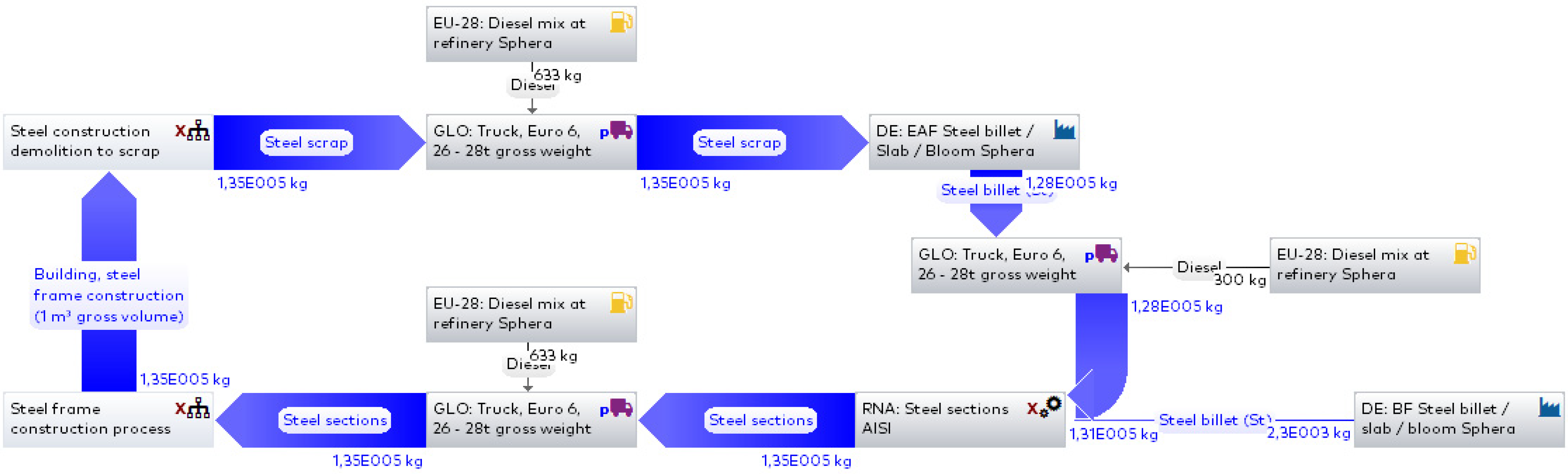
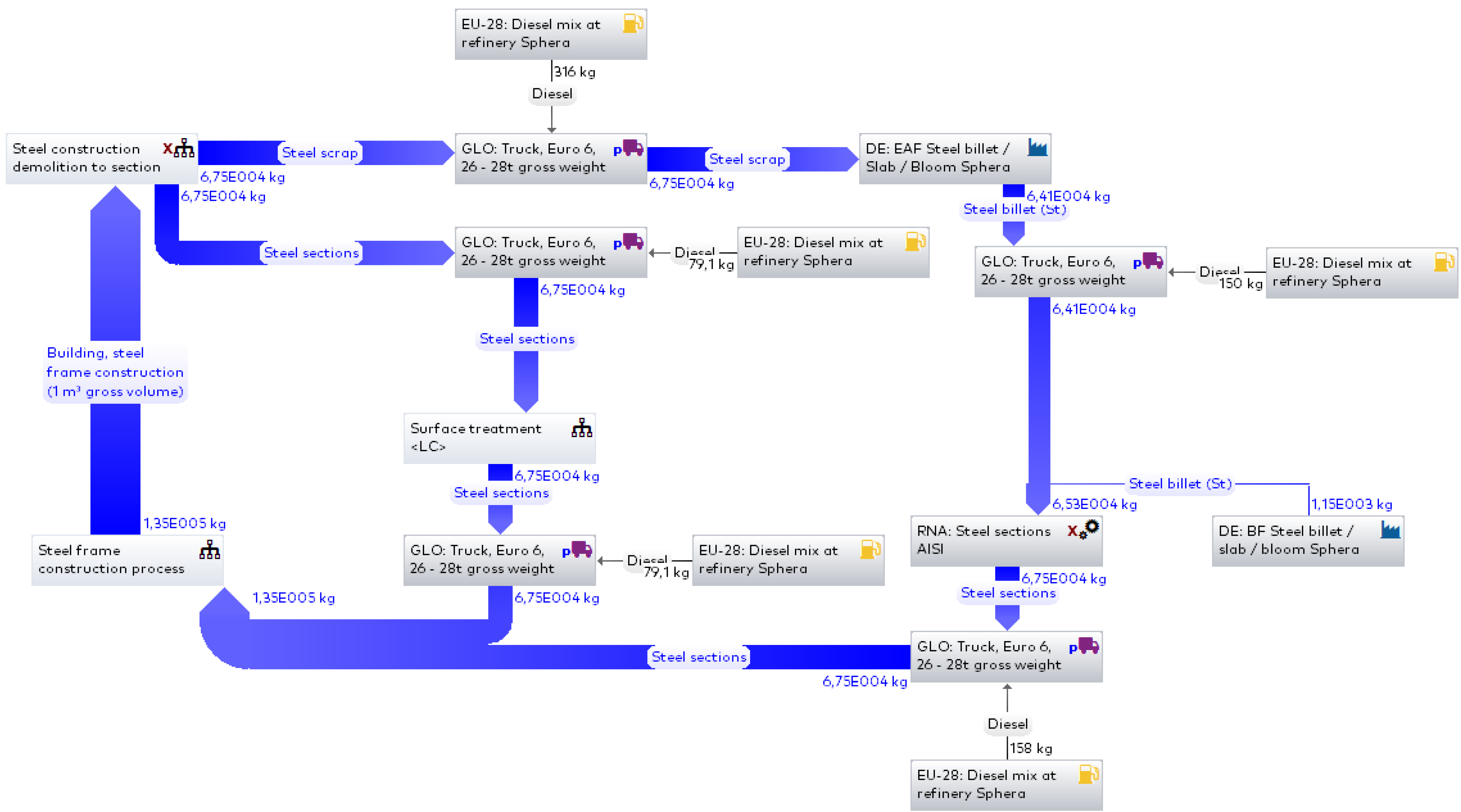
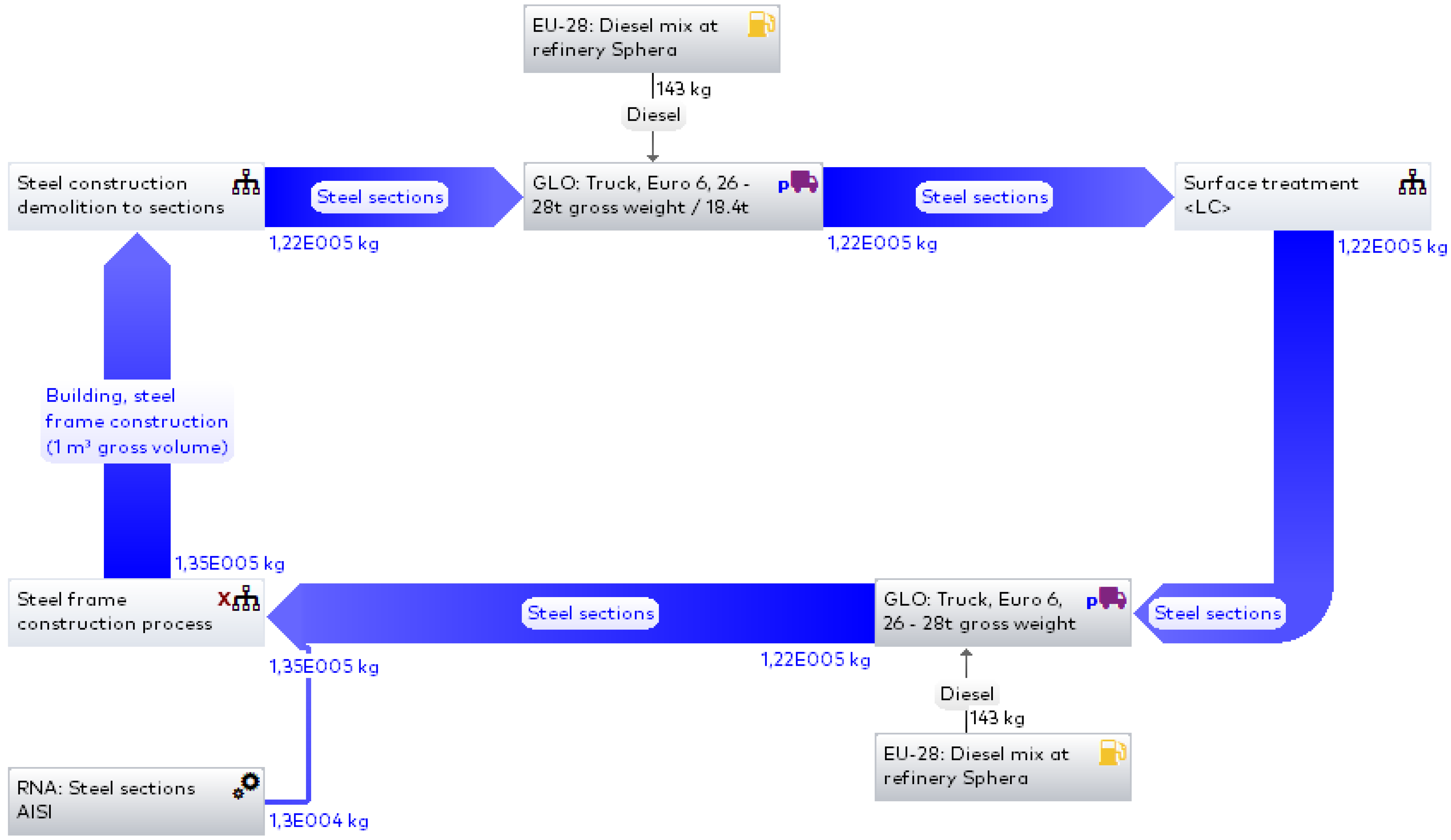
| Scenario No. | Demolition Material Mass | Weight of Recovered Elements | Mass of Steel for Remelting | Mass of Steel Obtained from Remelting | Additional Material for Manufacturing the Missing Elements |
|---|---|---|---|---|---|
| 1 | 135 t | - | 135 t | 128 t | 7 t |
| 2 | 135 t | 67.5 t | 67.5 t | 64.1 | 3.4 t |
| 3 | 135 t | 122 t | - | 13 t | |
Publisher’s Note: MDPI stays neutral with regard to jurisdictional claims in published maps and institutional affiliations. |
© 2022 by the authors. Licensee MDPI, Basel, Switzerland. This article is an open access article distributed under the terms and conditions of the Creative Commons Attribution (CC BY) license (https://creativecommons.org/licenses/by/4.0/).
Share and Cite
Broniewicz, E.; Dec, K. Environmental Impact of Demolishing a Steel Structure Design for Disassembly. Energies 2022, 15, 7358. https://doi.org/10.3390/en15197358
Broniewicz E, Dec K. Environmental Impact of Demolishing a Steel Structure Design for Disassembly. Energies. 2022; 15(19):7358. https://doi.org/10.3390/en15197358
Chicago/Turabian StyleBroniewicz, Elżbieta, and Karolina Dec. 2022. "Environmental Impact of Demolishing a Steel Structure Design for Disassembly" Energies 15, no. 19: 7358. https://doi.org/10.3390/en15197358
APA StyleBroniewicz, E., & Dec, K. (2022). Environmental Impact of Demolishing a Steel Structure Design for Disassembly. Energies, 15(19), 7358. https://doi.org/10.3390/en15197358