Article

Compact Ultra-Wideband Wilkinson Power Dividers Using Linearly Tapered Transmission Lines

1
Electrical Engineering Department, College of Engineering, Prince Sattam Bin Abdulaziz University, Al-Kharj 16278, Saudi Arabia
2
Faculty of Engineering and Information Technology, Taiz University, Taiz 6803, Yemen
3
Department of Electrical Engineering, King Saud University, Riyadh 11421, Saudi Arabia
*
Author to whom correspondence should be addressed.
Electronics 2022, 11(19), 3080; https://doi.org/10.3390/electronics11193080
Submission received: 9 August 2022 / Revised: 16 September 2022 / Accepted: 25 September 2022 / Published: 27 September 2022
(This article belongs to the Section Systems & Control Engineering)

Abstract

:
In this work, compact extended ultra-wideband (UWB) Wilkinson power dividers (WPDs) using tapered transmission lines are analyzed, designed, and measured. Utilizing carefully designed tapered transmission sections results in widening the operational bandwidth and reducing the element dimensions. Analytical models and design procedures of simple and compact and equal and unequal UWB WPDs based on linearly tapered transmission lines are developed and outlined in this paper. Four different configurations of equal and unequal power dividers are designed and presented. The number and locations of the isolation resistors have a noticeable effect on extending the operational bandwidth of the dividers. The presented designs of the WPDs have superior performance over extended bandwidths. The simulation and experimental results are in very good agreement with good insertion and return loss, good matching, and isolation, over the extended UWB operational bandwidth from 3 GHz to 27 GHz.

1. Introduction

Power dividers are passive microwave devices. They are either used to split the input power among n output ports or to combine the power from n ports to one output port (where n is the number of the input/output ports). Power dividers are generally used in several microwave systems, for example, in phase- shifters, amplifiers, and feeding networks of antenna arrays. The Wilkinson power divider (WPD) is popular since it has some advantages over other types of power dividers. All three ports of the WPD shown in Figure 1 can be matched, lossless, and isolated. Moreover, the WPD can also be designed for equal (−3 dB) or unequal power division.
Several designs and modifications have been presented in the literature for expanding the operational bandwidth of the traditional WPD. Extending the bandwidth of the WPD can be achieved using several techniques, such as utilizing multiple sections that broaden the bandwidth by increasing the cascaded sections [1], using tapered transmission lines (TTLs) [2], or by adding open-circuited stubs [3]. The multi-wafer packaging technique can also be used in the design of ultra-wideband (UWB) power dividers [4]. The utilization of TTLs in microwave components reduces the overall size of components and broadens the bandwidth [5,6]. In [7], the authors proposed a Wilkinson power divider with ultra-wideband performance using open-circuited stubs added to each branch. Additionally, open-circuited radial stubs can be used in the design of the ultra-wideband Wilkinson power divider [8,9]. Moreover, an ultra-wideband Wilkinson power divider open-circuited delta stub was proposed in [10]. Power dividers with UWB performance using tapered transmission lines on their sections were also proposed in [11,12,13,14].
For wideband applications, Wilkinson power dividers with multilayer substrates were introduced in [15]. This typically led to a circuit of a larger size. Another wideband Wilkinson power divider using non-uniform transmission lines was proposed and designed in [16]. This power divider attained an operational bandwidth extending from 3.1 GHz to 10.6 GHz. A wideband Wilkinson power divider with two cascaded sections of different electrical lengths and the same impedance was presented in [17]. Additionally, the authors in [18] proposed an UWB power divider using a square ring multiple-mode resonator. This power divider attained a bandwidth extending from 3.1 GHz to 10.6 GHz.
In this work, analysis, modeling, and implementations of novel designs of simple compact UWB WPDs with equal and unequal power division and extended operating bands are proposed. The proposed power dividers are based on sections of tapered transmission lines to reduce the component size and broaden the operational bandwidth of the designed components. The power dividers proposed in this work achieve considerable fractional bandwidth of 160% (3 GHz–27 GHz).

2. Analysis and Formulation

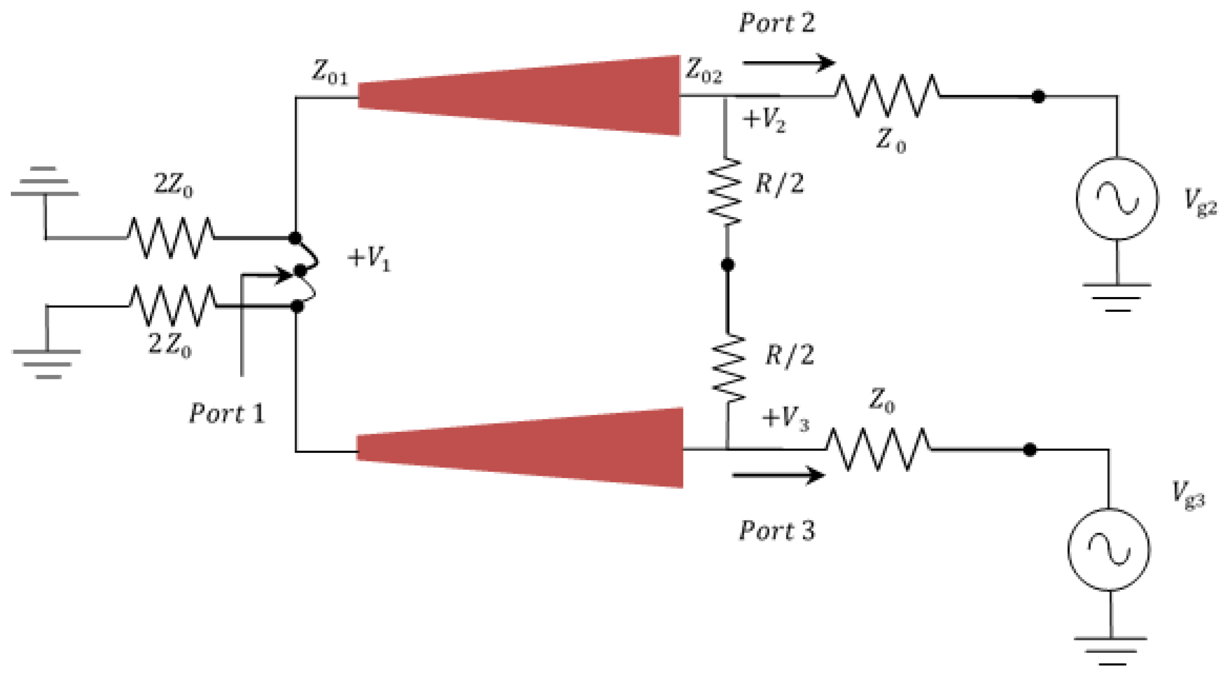
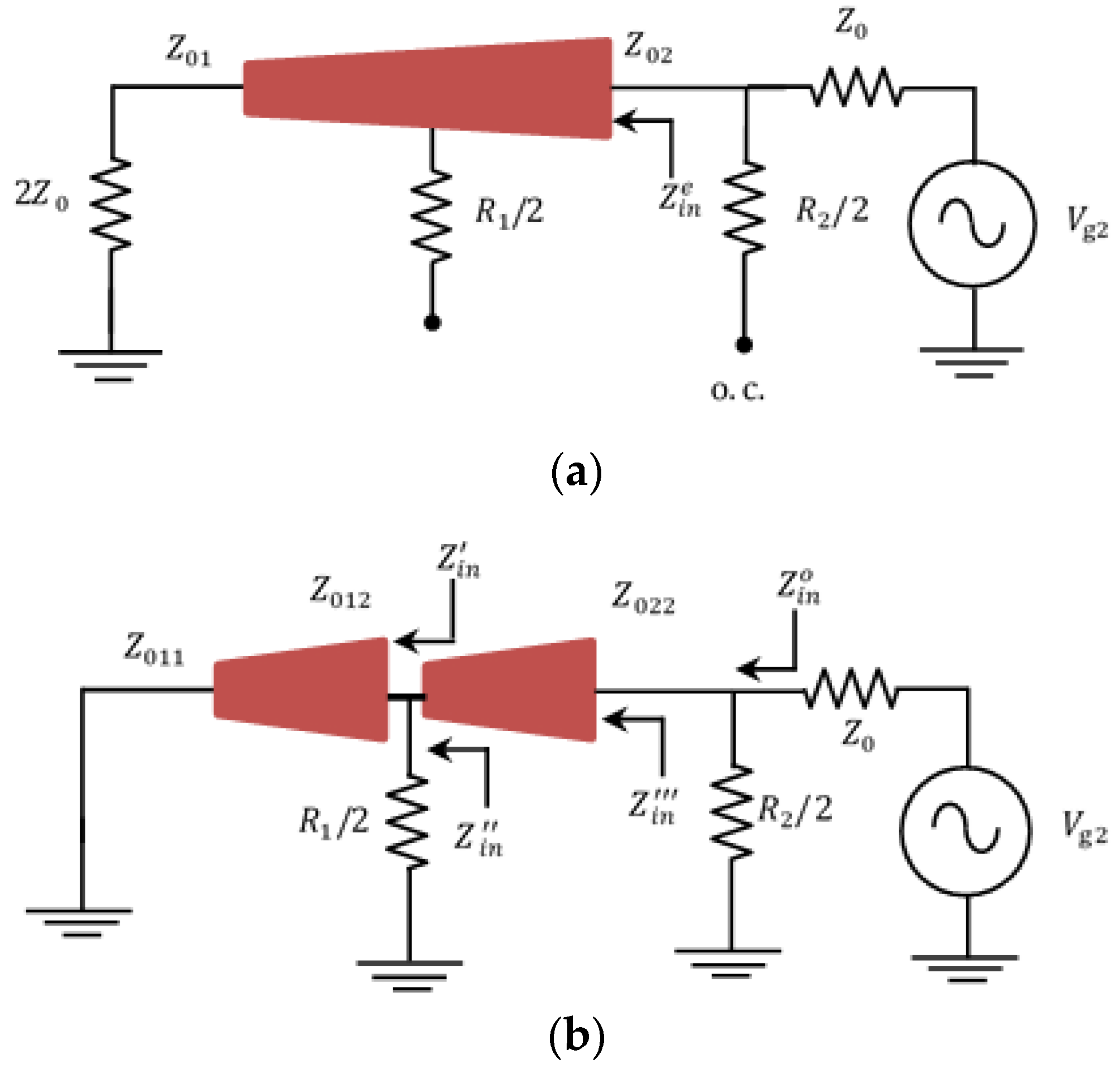
2.1. UWB WPD of Equal Power Splitting

In this section, the required analysis and modeling for the design of UWB WPDs based on TTLs are presented. The equivalent transmission line circuit shown in Figure 1 can be simplified by normalizing all impedances of the proposed power divider to the characteristic impedance Z 0 . For the purpose of analysis, the circuit shown in Figure 1 is redrawn with voltage sources at Port 2 and Port 3 (output ports) in Figure 2. The resulting circuit is symmetric through the midplane. Two modes of excitation exist in the power divider circuit. These modes are the even mode in which V g 2 = V g 3 = 2 V 0 and the odd mode where V g 2 = V g 3 = 2 V 0 .
In the case of even-mode excitation, where V g 2 = V g 3 = 2 V 0 and V 2 = V 3 , no current flows through the short circuit at Port 1 or in the R / 2 resistor that is connected between Port 2 and Port 3. Consequently, the circuit shown in Figure 2 can be bisected with open circuits, as shown in Figure 3a. For odd-mode excitation, where V g 2 = V g 3 = 2 V 0 and V 2 = V 3 , the voltage at the midpoints of the circuit shown in Figure 2 is equal to 0. Therefore, this circuit can be bisected with the ground at the midpoints, as depicted in Figure 3b.
The length of a linearly tapered quarter wavelength-equivalent impedance transformer is given by [5]
l = tan 1 ( ( 2 β / k ) 2 1 ) π 1 ( 2 β / k ) 2 λ 2
where β is the propagation constant, k is the tapered ratio, and λ is the guided wavelength. This length is calculated at the center frequency of the band (3.1–10.6) GHz (6.85 GHz).
The input impedance of the even-mode excitation circuit can be easily determined by looking into Port 2, which is the input of a tapered transmission line circuit. The load impedance Z L = Z 0 is reflected to the input of the tapered line and inverted with respect to the product of the terminal impedances of the tapered lines Z 01 and Z 02 . The input impedance of linearly tapered transmission lines (LTTLs) is expressed as [19]
Z i n = ( Z 01 Z 02 Z L ) ( j + Z L Z 02 c t ( a , b ) δ ( a , b ) ) ( Z 02 Z L C t ( a , b ) + j δ ( a , b ) )
where Z 01 = 2 Z 0 and Z 02 = Z 0 ,
c t ( a , b ) = J 1 ( a ) Y 0 ( b ) J 0 ( b ) Y 1 ( a ) J 0 ( a ) Y 0 ( b ) J 0 ( b ) Y 0 ( a )
C t ( a , b ) = J 1 ( b ) Y 0 ( a ) J 0 ( a ) Y 1 ( b ) J 1 ( a ) Y 1 ( b ) J 1 ( b ) Y 1 ( a )
δ ( a , b ) = J 0 ( a ) Y 0 ( b ) J 0 ( b ) Y 0 ( a ) J 1 ( a ) Y 1 ( b ) J 1 ( b ) Y 1 ( a )
with a = β / k , b = a ( 1 + k l ) , and J n ( x ) and Y n ( x ) are the Bessel functions of the first and second kind of order n , respectively. Consequently, this yields that the input impedance of the even-mode excitation circuit is
Z i n = Z 01 Z 02 Z L
For the odd-mode excitation, the input impedance can be found by looking into Port 2, where the load is short-circuited and the tapered transmission line acts as an inverter and transforms the short circuit load impedances into open circuit load impedances ( Z i n = ) at the input. Hence, for Port 2 to be matched for this mode of excitation, the value of the isolation resistance R should be selected such that R / 2 = Z 0 .
For a WPD with an extra resistor added in the middle at ( l / 2 ) of the tapered transmission line, the even and odd equivalent circuits are shown in Figure 4.
For that WPD, the input impedance of the even-mode excitation is given by
Z i n = Z 01 Z 02 Z L = Z 0
Additionally, the input impedance of the odd-mode excitation can be calculated by
Z i n o = ( R 2 / 2 ) | | Z i n
where
Z i n = Z 01 Z 02 Z i n j + Z i n Z 02 c t ( a , b ) δ ( a , b ) Z 02 Z i n C t ( a , b ) + j δ ( a , b )
Z i n = ( R 2 / 2 ) | | Z i n
Z i n = j Z m C t ( a , b )
and
Z m = Z 01 + Z 02 2
The resulting impedance in (8) can be computed to find the best combination of the resistors R 1 and R 2 that preserve superior impedance matching across the designed UWB, intrinsic to the tapered line sections. Designs of WPDs with three isolation resistors connected along the tapered line are utilized to effectively extend the bandwidth. The connected resistors are separated by l / 3 and the analysis is similar to that developed above. Additionally, Figure 5 shows the results obtained from the schematic circuit models of conventional WPDs and the proposed UWB Wilkinson power dividers. These results are obtained from the ADS simulation tool [20]. The conventional WPD has a fractional bandwidth of approximately 90%, with an input/output return loss greater than 10 dB.

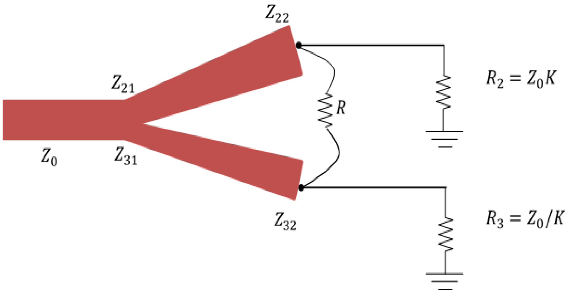
2.2. UWB WPD of Unequal Power Splitting

The presented designs of the UWB WPD based on tapered lines can also be used for unequally splitting the input power. Consider that the ratio of the power of Port 2 and Port 3 is K 2 = P 3 / P 2 . Starting from the design equation for traditional unequal WPDs [21], the following equations are derived for unequal UWB WPDs, using linearly tapered transmission lines shown in Figure 6:
Z 31 = Z 0 ( 1 + K 2 ) / K 3
Z 32 = Z 0 / K
Z 21 = K 2 Z 31
Z 22 = Z 0 K
R = Z 0 ( K + 1 / K )
The output transmission lines are matched to the impedances R 2 = Z 0 K and R 3 = Z 0 / K . A matching transformer is then used to transform these impedances to the characteristic impedance Z 0 .

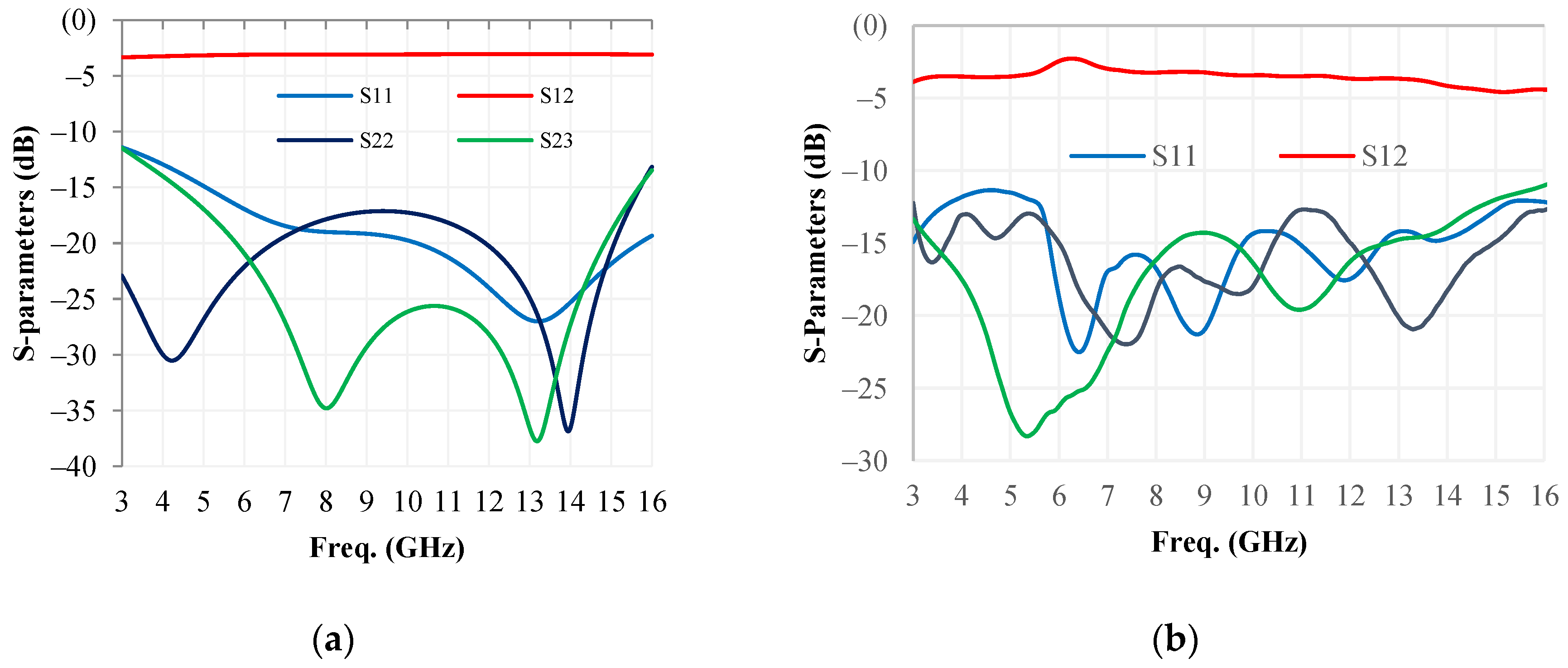
3. Results and Discussion

In this section, the designed WPDs using linearly tapered transmission lines were simulated and fabricated. The simulation was achieved using a CST software tool with a time-domain solver and waveguide ports [22]. A Roger RT-5880 substrate of thickness 0.508 mm and dielectric constant of 2.2 was used for this purpose. The proposed microstrip UWB Wilkinson power dividers were fabricated using a laser etching system. Moreover, the experimental results were obtained using a vector network analyzer with a testing fixture.
The simulated and measured results of a Wilkinson power divider with one isolation resistor are depicted in Figure 7. This circuit was designed to work within the frequency range of 3.1 GHz to 10.6 GHz. The resulting overall size of the designed circuit was 13.14 mm × 10.71 mm and the isolation resistor (surface-mount device (SMD)) R = 100 Ω. The simulation results and measurement results are shown in Figure 7a,b, respectively. The simulation results and measurement results demonstrated good performance of insertion loss (i.e., ~−3 dB) and also showed good performance of return loss (11 dB) over the entire operational bandwidth. Equal power division was achieved among the output ports with isolation greater than 11 dB.
Another UWB WPD with two isolation resistors was designed to work in the frequency band extending from 3 GHz to 16 GHz. The size of this WPD was 16.97 mm × 11.51 mm and the isolation resistors R 1 = 100   Ω and R 2 = 200   Ω . Figure 8 shows the simulation results and measurement results of the proposed ultra-wideband WPD. These results also demonstrated good performance of insertion loss (i.e., ~−3 dB) and also demonstrated good performance of return loss (i.e., greater than 12 dB) over the entire operational band (3–16 GHz). Moreover, equal power division was achieved between the output ports with isolation greater than 12 dB.
Following this, a third design that had a substantial UWB with superior performance was presented. This WPD design utilized three isolation resistors with the designed taper sections. The overall size of this power divider was 16.47 mm × 11.51 mm with optimized resistor values of R 1 = 100   Ω , R 2 = 120   Ω , and R 3 = 200   Ω . The simulation results and measurement results of the designed ultra-wideband Wilkinson power divider are shown in Figure 9. These results also demonstrated good performance of insertion loss (i.e., ~−3 dB) and also demonstrated good performance of return loss (i.e., greater than 11 dB) over the entire operational band (3–27 GHz). Additionally, equal power division was achieved between the output ports with isolation greater than 10 dB.
Finally, an unequal WPD with UWB performance was designed, simulated, and fabricated. For P 3 = 2 P 2 , the obtained simulation results and measurement results of this WPD are shown in Figure 10. One resistor was used as an isolation resistor in the design. The overall size of this power divider was 18.36 mm × 11.7 mm. The simulation results and measurement results demonstrated good insertion loss (i.e., ~−2 dB for Port 3 and −5 dB for Port 2). Furthermore, there was good performance of return loss (i.e., greater than 12 dB) over the entire UWB frequency band.
The performance obtained from the proposed UWB Wilkinson power divider around the mid of the operational bandwidth are summarized in Table 1. Moreover, Table 2 shows a performance comparison with ultra-wideband Wilkinson power dividers designed using various techniques and approaches. Figure 11 shows the photograph of the fabricated UWB WPD circuits.

4. Conclusions

This paper presented compact and simple UWB WPDs using linearly tapered transmission lines. The analysis and the design approach of equal and unequal extended UWB power dividers were also developed and reported through this work. The number and locations of the isolation resistors had a perceptible effect on extending the operational bandwidth of the dividers. Good power division, matching, and isolation, over the designed spectrum range were achieved, as verified by simulation results and experimental results over the extended operational bandwidth of 24 GHz from 3 GHz to 27 GHz.

Author Contributions

Conceptualization, F.R. and M.A.S.A.; methodology, F.R. and M.A.S.A.; software, F.R. validation, F.R. formal analysis, M.A.S.A., F.R. and S.M.S.; investigation, F.R. and S.M.S.; resources, F.R. and. M.A.S.A.; data curation, F.R.; writing—original draft preparation, F.R.; writing—review and editing, F.R. and M.A.S.A. and S.M.S.; visualization, F.R. and S.M.S.; supervision, M.A.S.A.; project administration, F.R.; funding acquisition, F.R. All authors have read and agreed to the published version of the manuscript.

Funding

The authors extend their appreciation to the Deputyship for Research & Innovation, Ministry of Education in Saudi Arabia for funding this research work through the project number IF-PSAU-2021- 01/18746.

Institutional Review Board Statement

Not applicable.

Informed Consent Statement

Not applicable.

Data Availability Statement

Not applicable.

Conflicts of Interest

The authors declare no conflict of interest.

References

  1. Pazoki, R.; Fard, M.G.; Fard, H.G. A modification in the single-stage wilkinson power divider to obtain wider bandwidth. In Proceedings of the 2007 Asia-Pacific Microwave Conference, Bangkok, Thailand, 11–14 December 2007; pp. 1–4. [Google Scholar]
  2. Mencia-Oliva, B.; Pelaez-Perez, A.; Almorox-Gonzalez, P.; Alonso, J. New technique for the design of ultra-broadband power dividers based on tapered lines. In Proceedings of the 2009 IEEE MTT-S International Microwave Symposium Digest, Boston, MA, USA, 7–12 June 2009; pp. 493–496. [Google Scholar]
  3. Yi, K.-H.; Kang, B. Modified Wilkinson power divider for nth harmonic suppression. IEEE Microw. Wirel. Compon. Lett. 2003, 13, 178–180. [Google Scholar] [CrossRef]
  4. Lan, X.; Chang-Chien, P.; Fong, F.; Eaves, D.; Zeng, X.; Kintis, M. Ultra-Wideband Power Divider Using Multi-Wafer Packaging Technology. IEEE Microw. Wirel. Compon. Lett. 2010, 21, 46–48. [Google Scholar] [CrossRef]
  5. Womack, C.P. The use of exponential transmission lines in microwave components. IRE Trans. Microw. Theory Tech. 1962, 10, 124–132. [Google Scholar] [CrossRef]
  6. Razzaz, F.; Saeed, S.M.; Alkanhal, M.A.S. Ultra-Wideband Bandpass Filters Using Tapered Resonators. Appl. Sci. 2022, 12, 3699. [Google Scholar] [CrossRef]
  7. Ou, X.-P.; Chu, Q.-X. A modified two-section UWB Wilkinson power divider. In Proceedings of the 2008 International Conference on Microwave and Millimeter Wave Technology, Nanjing, China, 21–24 April 2008; pp. 1258–1260. [Google Scholar]
  8. Ahmed, O.; Sebak, A.-R. A modified Wilkinson power divider/combiner for ultrawideband communications. In Proceedings of the 2009 IEEE Antennas and Propagation Society International Symposium, North Charleston, SC, USA, 1–5 June 2009; pp. 1–4. [Google Scholar]
  9. Zhou, B.; Wang, H.; Sheng, W. A novel UWB Wilkinson power divider. In Proceedings of the The 2nd International Conference on Information Science and Engineering, Hangzhou, China, 4–6 December 2010; pp. 1763–1765. [Google Scholar]
  10. Zhou, B.; Wang, H.; Sheng, W.-X. A modified UWB Wilkinson power divider using delta stub. Prog. Electromagn. Res. Lett. 2010, 19, 49–55. [Google Scholar] [CrossRef]
  11. Chiang, C.T.; Chung, B.K. Ultra wideband power divider using tapered line. Prog. Electromagn. Res. 2010, 106, 61–73. [Google Scholar] [CrossRef]
  12. Jia, Z.; Zhu, Q.; Ao, F. A 2-way broad-band microstrip matched power divider. In Proceedings of the 2006 International Conference on Communications, Circuits and Systems, Guilin, China, 25–28 June 2006; pp. 2592–2596. [Google Scholar]
  13. Al Shamaileh, K.A.; Dib, N.; Abbosh, A. Analysis and Design of Ultra-Wideband Unequal-Split Wilkinson Power Divider Using Tapered Lines Transformers. Electromagnetics 2012, 32, 426–437. [Google Scholar] [CrossRef]
  14. Razzak, F.; Alkanhal, M.; Sheta, A.-F. UWB Wilkinson power divider using tapered transmission lines. In Proceedings of the PIERS Proceedings, Moscow, Russia, 19–23 August 2012. [Google Scholar]
  15. Nor, M.Z.B.M.; Rahim, S.K.A.; bin Sabran, M.I.; Rani, M.S.B.A. Wideband planar Wilkinson power divider using double-sided parallel-strip line technique. Prog. Electromagn. Res. C 2013, 36, 181–193. [Google Scholar] [CrossRef]
  16. Al Shamaileh, K.; Almalkawi, M.; Devabhaktuni, V.K.; Dib, N.I.; Henin, B.; Abbosh, A.M. Non-uniform transmission line ultra-wideband wilkinson power divider. Prog. Electromagn. Res. C 2013, 44, 1–11. [Google Scholar] [CrossRef]
  17. Dardeer, O.; Abouelnaga, T.; Mohra, A.; Elhennawy, H. Compact UWB Power Divider, Analysis and Design. J. Electromagn. Anal. Appl. 2017, 9, 9–21. [Google Scholar] [CrossRef] [Green Version]
  18. Weng, M.; Song, Y.; Zhao, J. Design of compact microstrip UWB power divider using square ring multiple-mode resonator. In Proceedings of the 2015 Asia-Pacific Microwave Conference (APMC), Nanjing, China, 6–9 December 2015; pp. 1–3. [Google Scholar]
  19. Rustogi, O.P. Linearly Tapered Transmission Line and Its Application in Microwaves (Correspondence). IEEE Trans. Microw. Theory Tech. 1969, 17, 166–168. [Google Scholar] [CrossRef]
  20. Keysight. PathWave Advanced Design System. Keysight. Available online: https://www.keysight.com/us/en/products/software/pathwave-design-software/pathwave-advanced-design-system.html (accessed on 8 August 2022).
  21. Pozar, D.M. Microwave Engineering; John Wiley & Sons: Hoboken, NJ, USA, 2011. [Google Scholar]
  22. CST Studio Suite 3D EM Simulation and Analysis Software. Available online: https://www.3ds.com/products-services/simulia/products/cst-studio-suite/ (accessed on 8 August 2022).
  23. Habibi, H.; Miar Naimi, H. Taper transmission line UWB Wilkinson power divider analysis and design. Int. J. Electron. 2019, 106, 1332–1343. [Google Scholar] [CrossRef]
  24. Chang, L.; Liao, C.; Chen, L.-L.; Lin, W.; Zheng, X.; Wu, Y.-L. Design of an ultra-wideband power divider via the coarse-grained parallel micro-genetic algorithm. Prog. Electromagn. Res. 2012, 124, 425–440. [Google Scholar] [CrossRef]
  25. Yang, Z.; Luo, B.; Dong, J.; Yang, T. Ultra-wideband power divider employing coupled line and short-ended stub. Microw. Opt. Technol. Lett. 2016, 58, 713–715. [Google Scholar] [CrossRef]
  26. Osman, S.A.M.; El-Tager, A.M.E.; Abdelghany, F.I.; Hafez, I.M. Two-way modified Wilkinson power divider for UWB applications using two sections of unequal electrical lengths. Prog. Electromagn. Res. C 2016, 68, 221–233. [Google Scholar] [CrossRef] [Green Version]
Figure 1. WPD with tapered transmission lines.
Electronics 11 03080 g001
Figure 2. WPD in symmetric form.
Electronics 11 03080 g002
Figure 3. Equivalent circuits: (a) even mode (b) odd mode.
Electronics 11 03080 g003
Figure 4. Equivalent circuits of two isolation resistors: (a) even mode (b) odd mode.
Electronics 11 03080 g004
Figure 5. Schematic circuit model S-parameters results of the conventional WPD and proposed UWB WPD, (a) conventional WPD, (b) one-isolation resistor, (c) two-isolation resistors, (d) three-isolation resistors.
Electronics 11 03080 g005
Figure 6. Unequal UWB WPD.
Electronics 11 03080 g006
Figure 7. Results of UWB-WPD with one isolation resistor: (a) simulated (b) measured.
Electronics 11 03080 g007
Figure 8. Results of UWB-WPD with two isolation resistors: (a) simulated (b) measured.
Electronics 11 03080 g008
Figure 9. Results of UWB-WPD with three isolation resistors: (a) simulated (b) measured.
Electronics 11 03080 g009
Figure 10. Results of UWB-WPD unequal power division: (a) simulated (b) measured.
Electronics 11 03080 g010
Figure 11. Photograph of the proposed ultra-wideband Wilkinson power dividers, (a) with two-isolation resistors, (b) with three-isolation resistors.
Electronics 11 03080 g011
Table 1. Obtained performance from the proposed UWB WPDs over the mid of the operational bandwidth.
WPD with One-Isolation
Resistor
WPD with Two-Isolation
Resistors
WPD with Three-Isolation
Resistors
SimulationMeasurementsSimulationMeasurementsSimulationMeasurements
Insertion loss (dB) 3.15 3.76 3.1 3.54 3.14 3.85
Return loss (input) (dB) 15 15 20 15 15 12
Return loss (output) (dB) 20 20 15 15 15 13
Isolation (dB) 20 20 25 15 20 13
Table 2. Performance comparison with other wideband WPDs.
ReferenceNo. of Isolation ResistorsBandwidth (GHz)Input Return Loss (dB)Output Return Loss (dB)Isolation (dB)Arm Length (mm)Techniques
[16]33.1–10.613131010Non-uniform transmission lines
[23]23.1–11.012151211TTLs
[24]22.5–10.615151518Exponential and elliptical TTL
[25]13.1–10.610.314.410.111.6Short-ended stub with the open-ended line
[18]12.1–11.710Not given1015.1Square ring multiple-mode resonator
[26]23.1–10.61014.513.513.43Multi-section transmission lines
This work13.1–10.61111118.3LTTLs
23.0–16.01212129.5
33.0–27.01111109.6
Publisher’s Note: MDPI stays neutral with regard to jurisdictional claims in published maps and institutional affiliations.

