Article

Corrosion Resistance of Aluminum Alloy AA2024 with Hard Anodizing in Sulfuric Acid-Free Solution

by
José Cabral Miramontes
1,*,
Citlalli Gaona Tiburcio
1,
Estefanía García Mata
1,
Miguel Ángel Esneider Alcála
2,
Erick Maldonado-Bandala
3,
Maria Lara-Banda
1,
Demetrio Nieves-Mendoza
3,
Javier Olguín-Coca
4,
Patricia Zambrano-Robledo
1,
Luis Daimir López-León
4 and
Facundo Almeraya Calderón
1,*
1
Universidad Autónoma de Nuevo León, FIME-Centro de Investigación e Innovación en Ingeniería Aeronáutica (CIIIA), Av. Universidad s/n, Ciudad Universitaria, San Nicolás de los Garza 66455, Mexico
2
Centro de Investigación en Materiales Avanzados Subsede Monterrey (CIMAV), Alianza Norte 202, PIIT, Autopista Monterrey-Aeropuerto, Km 10, Apodaca, Nuevo León 66628, Mexico
3
Facultad de Ingeniería Civil, Universidad Veracruzana, Xalapa 91000, Mexico
4
Área Académica de Ingeniería y Arquitectura, Universidad Autónoma del Estado de Hidalgo, 42082 Carretera Pachuca-Tulancingo, Km 4.5, Hidalgo 42082, Mexico
*
Authors to whom correspondence should be addressed.
Materials 2022, 15(18), 6401; https://doi.org/10.3390/ma15186401
Submission received: 4 August 2022 / Revised: 7 September 2022 / Accepted: 8 September 2022 / Published: 15 September 2022
(This article belongs to the Special Issue Anodized Materials and Their Applications)

Abstract

:
In the aeronautical industry, Al-Cu alloys are used as a structural material in the manufacturing of commercial aircraft due to their high mechanical properties and low density. One of the main issues with these Al-Cu alloy systems is their low corrosion resistance in aggressive substances; as a result, Al-Cu alloys are electrochemically treated by anodizing processes to increase their corrosion resistance. Hard anodizing realized on AA2024 was performed in citric and sulfuric acid solutions for 60 min with constant stirring using current densities 3 and 4.5 A/dm2. After anodizing, a 60 min sealing procedure in water at 95 °C was performed. Scanning electron microscopy (SEM) and Vickers microhardness (HV) measurements were used to characterize the microstructure and mechanical properties of the hard anodizing material. Electrochemical corrosion was carried out using cyclic potentiodynamic polarization curves (CPP) and electrochemical impedance spectroscopy (EIS) in a 3.5 wt. % NaCl solution. The results indicate that the corrosion resistance of Al-Cu alloys in citric acid solutions with a current density 4.5 A/dm2 was the best, with corrosion current densities of 2 × 10⁻⁸ and 2 × 10⁻⁹ A/cm2. Citric acid-anodized samples had a higher corrosion resistance than un-anodized materials, making citric acid a viable alternative for fabricating hard-anodized Al-Cu alloys.

1. Introduction

In the aeronautical industry, aluminum alloys are used for their low cost and combination of properties [1]. Since their invention in 1825, aluminum alloys have been known to provide significant benefits to the aeronautical industry. They are, thus, one of the most used materials for aircraft structures where fatigue and corrosion resistance are required [2,3]. The 2XXX (Al-Cu) series is one of the most used for fabricating structures that are sensitive to fatigue, damage tolerant, and require a high specific resistance. AA2024 alloy is used in the fuselage (bulkheads and longerons), internal structures (trusses), and non-structural components [4,5,6,7]. The 2XXX (Al-Cu) series aluminum has mainly Cu in its chemical composition and is used for its superior mechanical properties. However, the presence of the high Cu content results in corrosion problems due to poor anodic coating quality [3,8]. In addition, the aluminum alloy AA2024 presents Cu, Fe, Si, Mn, and Mg, among other elements [9]. Additionally, the humidity in the air can form reactive atomic hydrogen in aluminum alloys. As a result, a significant element impacting the mechanical characteristics of the metal can be the relative humidity (RH) in the atmosphere [10]. The main advantage of AA2024 for aircraft structural components is that it provides good fatigue resistance and lower corrosion resistance, as mentioned previously [8]. Nevertheless, AA2024 can also be found in general aircraft parts including shear webs and ribs, gears, bolts, couplings, hydraulic valves, pistons, avionics, etc. [11]. AA2024 is a trusted material because of its tensile strength, achieving up to 483 MPa, and elasticity modulus of 73.1 GPa. All these properties make the Al alloys a good option for any conditions [12].
Furthermore, the anodizing process is the most popular and cheapest option to improve corrosion resistance and achieve better properties for aluminum alloys [1,13]. Anodizing is an electrochemical process by which several conditions influence the mechanical properties, chemical composition, and morphology by creating an anodic oxide film on the aluminum alloy’s surface [14,15]. The resulting properties of the oxide film are thickness, hardness, and elasticity, which can vary depending on the electrolyte used in the anodizing cell [16]. However, several factors affect the anodizing process, such as the type of aluminum alloy, the processing time, the concentration of each solution, temperature, potential applied to the cell, current density, sealing process, etc. [17,18] Some advantages of the anodizing process are increasing corrosion and abrasion resistance, improving paint adhesion, and creating a dielectric layer [14]. One of the most important anodizing methods for AA2024 in aeronautical applications is hard anodizing (hard coats or type III anodizing). Hard anodizing produces a hard anodic film on the aluminum alloy by considering the operating temperatures, use of addition agents, and the voltage and current density, which differ from the common sulfuric acid method or type II. The hard anodizing creates a heavier coating, expected to be up to >3 GPa at 25 µm film thickness [14,18,19]. This process is commonly given by a pretreatment process, where the alloys can be degreased with acetone and rinsed in deionized water. Following that, etching proceeds in the acid bath. Finally, the anodizing treatment is performed in the desirable solutions (inorganic acids) and sealed at high temperatures (up to 90 °C) [20,21]. Nevertheless, it is crucial to keep in mind that the hard coatings are exposed to form linear pores and cells in the morphology of the anodic film while enhancing corrosion resistance and proper paint adhesion [22].
Over the decades, optimization of the anodizing process has been needed to minimize every type of corrosion and reach the expected product lifetime [15]. However, it has been a challenging demand since the expectations must also meet the environmental standards while preserving energy efficiency [23]. Unfortunately, for most type III hard coatings, it is common to use sulfuric and chromic acid solutions, which are hazardous to human health [24,25]. In contrast, several studies show that the higher the acid concentration, the greater the thickness in the anodic film [26], leading to the minimizing of sulfuric and chromic acid. In addition, organic acids have proven to be the best options for replacing the inorganic ones [27], citric acid being one of the most predominant and having an overall great performance in aluminum alloy. At the same time, higher concentrations are not needed to provide protection and better properties in the anodic film [24,28]. This work aims to develop a surface treatment for the manufacture of type III hard anodizing free chromic and sulfuric acid solutions in Al-Cu alloys and to evaluate its corrosion resistance and microhardness properties.

2. Materials and Methods

2.1. Materials

A commercial AA2024 alloy in the shape of a 50-mm-diameter rod was used, and 5-mm-thick discs were cut to anodize and evaluate using electrochemical techniques.
AA2024 samples were polished per ASTM E3 and E407 standards [29,30] prior to anodization with SiC grit papers: 180, 220, 320, 400, and 600 grades, followed by 10 min of ultrasonic cleaning in deionized water.

2.2. Anodizing Process

Anodizing procedure included 5 s of pickling in a 50 wt. % HCl solution, followed by rinses in deionized water. AA2024 was anodized using mix of bath solutions, which included the following: 1 M sulfuric acid as a control, a solution composed of a 1 M citric acid concentration with additions of 5 mL/L and 10 mL/L of the sulfuric acid solution, and finally a bath composed of a concentration of 1 M citric acid (C6H8O7·H2O) to give a total of four solutions used to produce anodized AA 2024. It used a lead bar as a cathode because they have a more noble behavior than aluminum alloy AA2024, and a Model XLN30052-GL High Power Programmable DC Power Supply (CA, USA) was used as the current generator. The parameters used in the anodizing process were the anodizing electrolyte baths and the current densities of 3 and 4.5 A/dm2 [31]. The anodization was carried out in a cold-water bath at a temperature of 0 °C ± 2 °C for 60 min for each of the solutions individually with constant stirring of the solution. The anodizing current density and time strongly depend on the electrolyte species used during anodizing, to grow such a thick oxide, current densities can be markedly higher than those used to grow type II oxides, depending upon how the components are manufactured and the complexity of the alloy. After anodizing, a 5 s rinse in deionized water was followed by 60 min sealing in deionized water at 95 °C. Hot-water sealing reduces or eliminates porosity in anodizing and improves corrosion resistance [32]. Parameters of the anodizing treatment are shown in Table 1.

2.3. Microstructural Characterization

Microstructural characterization was performed by scanning electron microscope (SEM, Jeol JSM 6510LV, Tokyo, Japan) to analyze the surface morphology and thickness of oxide layer (cross-section) of the anodized samples at a magnification of 2000×, a voltage of 20 kV, and a working distance (WD) of 8.5 mm. Backscattered electrons (BSE) were used to observe the morphology by SEM, and energy dispersive X-ray spectroscopy (EDS) was used to determine the chemical composition of cross-sections.

2.4. Vickers Microhardness Measurements

Vickers microhardness measurements were made in cross-section of anodized samples in a microhardness tester (Wilson Tester 402 MVD, Lake Bluff, IL, USA) using a load 0.05 gf and a dwell time 15 s, with 15 readings per sample.

2.5. Electrochemical Techniques

Electrochemical corrosion measurements were performed using a three-electrode cell, and a Potentiostat/Galvanostat/ZRA (Solartron 1287A, Bognor Regis, UK). All tests were by immersion in a 3.5 wt. % sodium chloride solution at room temperature and were performed in triplicate. Electrochemical techniques used were cyclic potentiodynamic polarization (CPP) and electrochemical impedance spectroscopy (EIS) [33,34]. CPP was measured with a potential scan from −0.3 to 1.0 V vs. SCE from corrosion potential (Ecorr) using a complete polarization cycle at a sweep rate of 0.06 V/min following the ASTM G61-11 standard [35,36,37,38,39,40]. EIS has measured a frequency range of 0.01 to 100,000 Hz, obtaining 35 points per decade and using a 10 mV RMS amplitude by the ASTM G106-15 standard [41,42,43,44,45,46,47,48].

3. Results

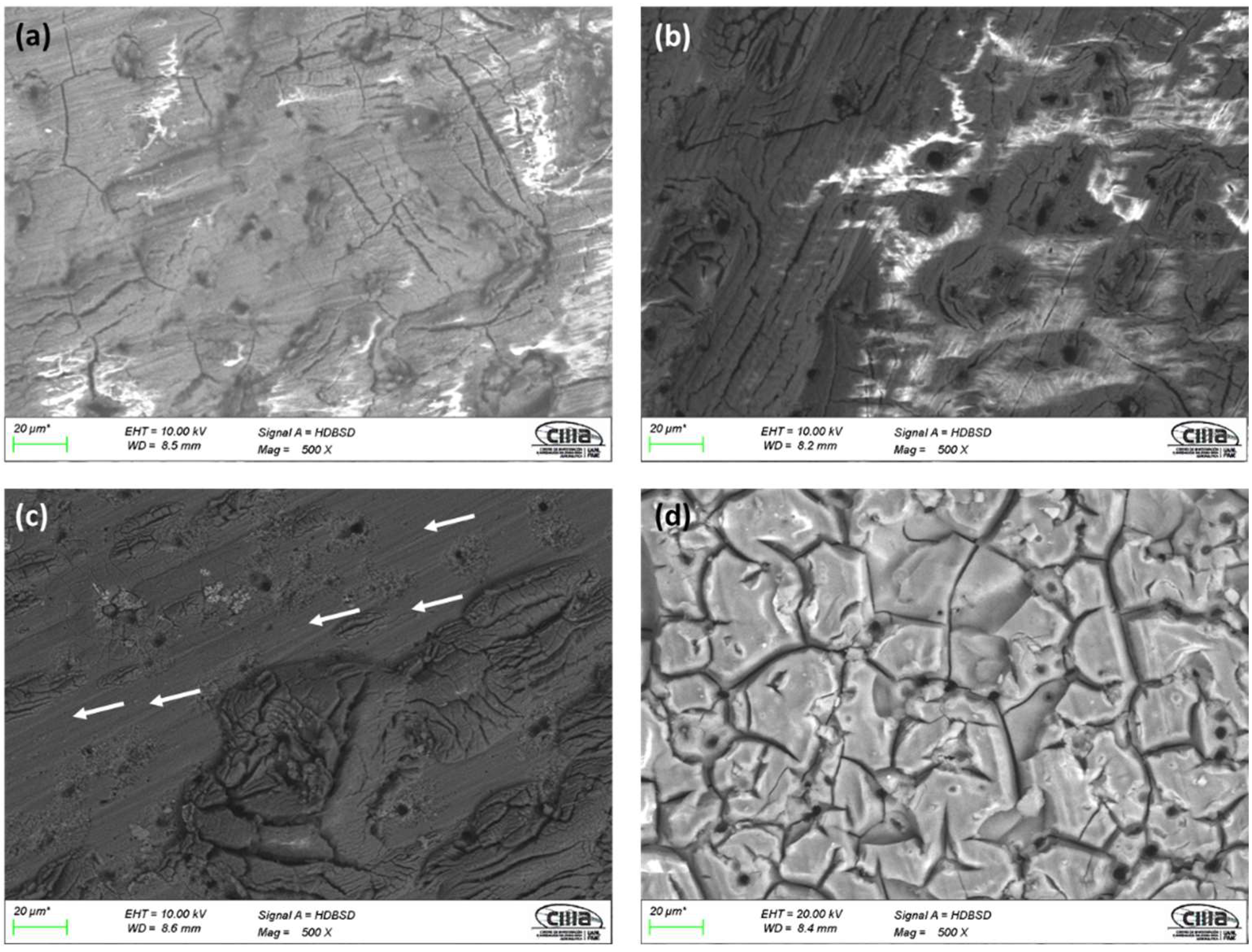
3.1. Microstructural Characterization by SEM

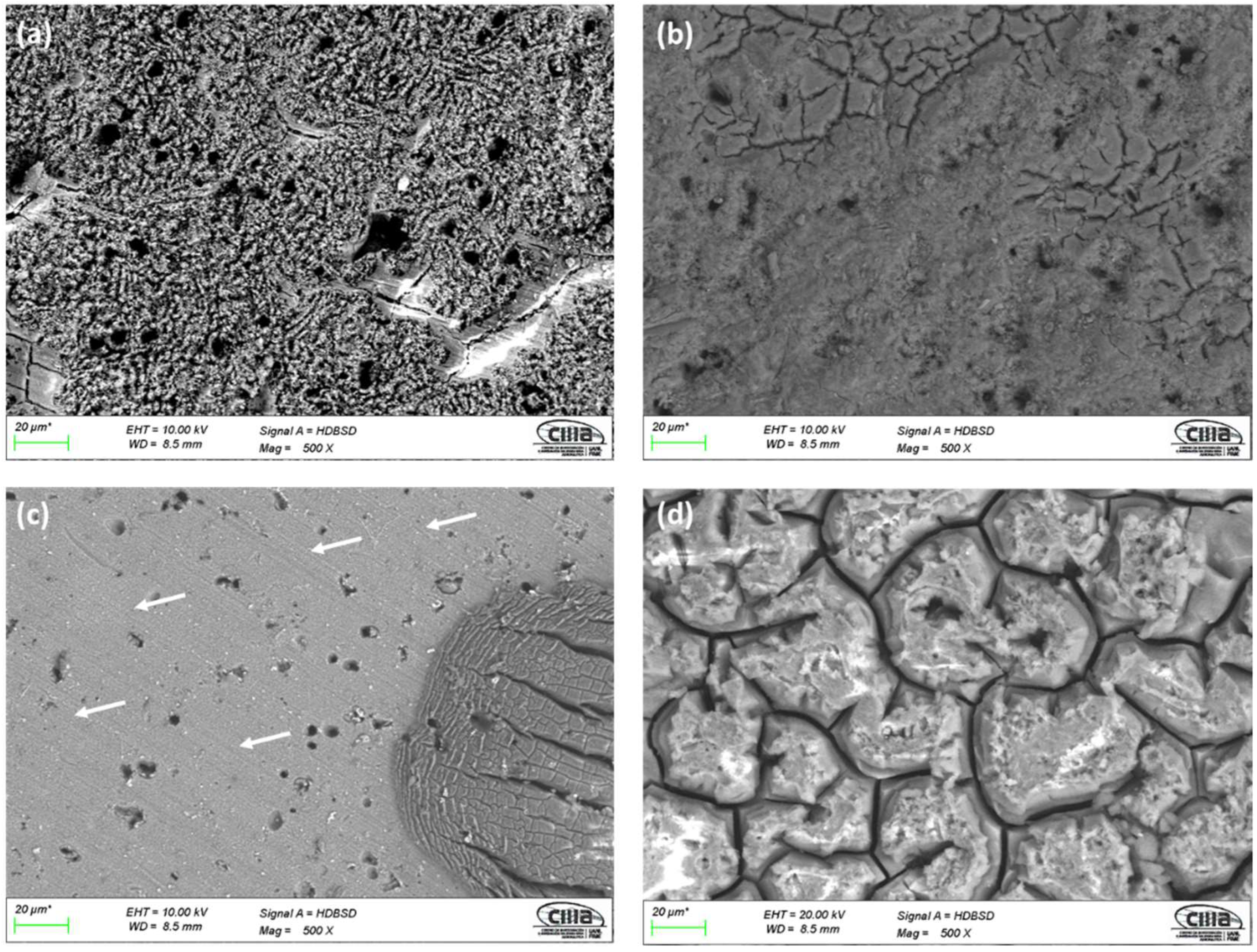
3.1.1. Surface Morphology

Surface morphology obtained by SEM using backscattered electrons (BSE) for anodized samples can be seen in Figure 1 and Figure 2. All the samples prepared with an i = 3 A/dm2 and the anodizing solutions have porosity and surface cracks. The sample anodized in 1 M citric acid solution (3A C1M) shows areas without anodizing, indicated by arrows in Figure 1c, as well as surface porosity and cracking. In all cases, anodized samples with an i = 4.5 A/dm2 in the various solutions exhibited the same behavior, cracking and surface porosity. Similarly, the anodized sample in 1 M citric acid solution (4.5A C1M) has areas that are not anodized, as indicated by the arrows in Figure 2c. In all cases, the porosity may be related to the intermetallic copper compounds, which do not allow a homogeneous growth of the anodizing layer; on the other hand, the cracking may be due to surface stresses caused by the growth of the anodizing film or to thermal shock that occurs when going from a cold-water bath in the anodizing process to a bath at 95 °C for the sealing process.

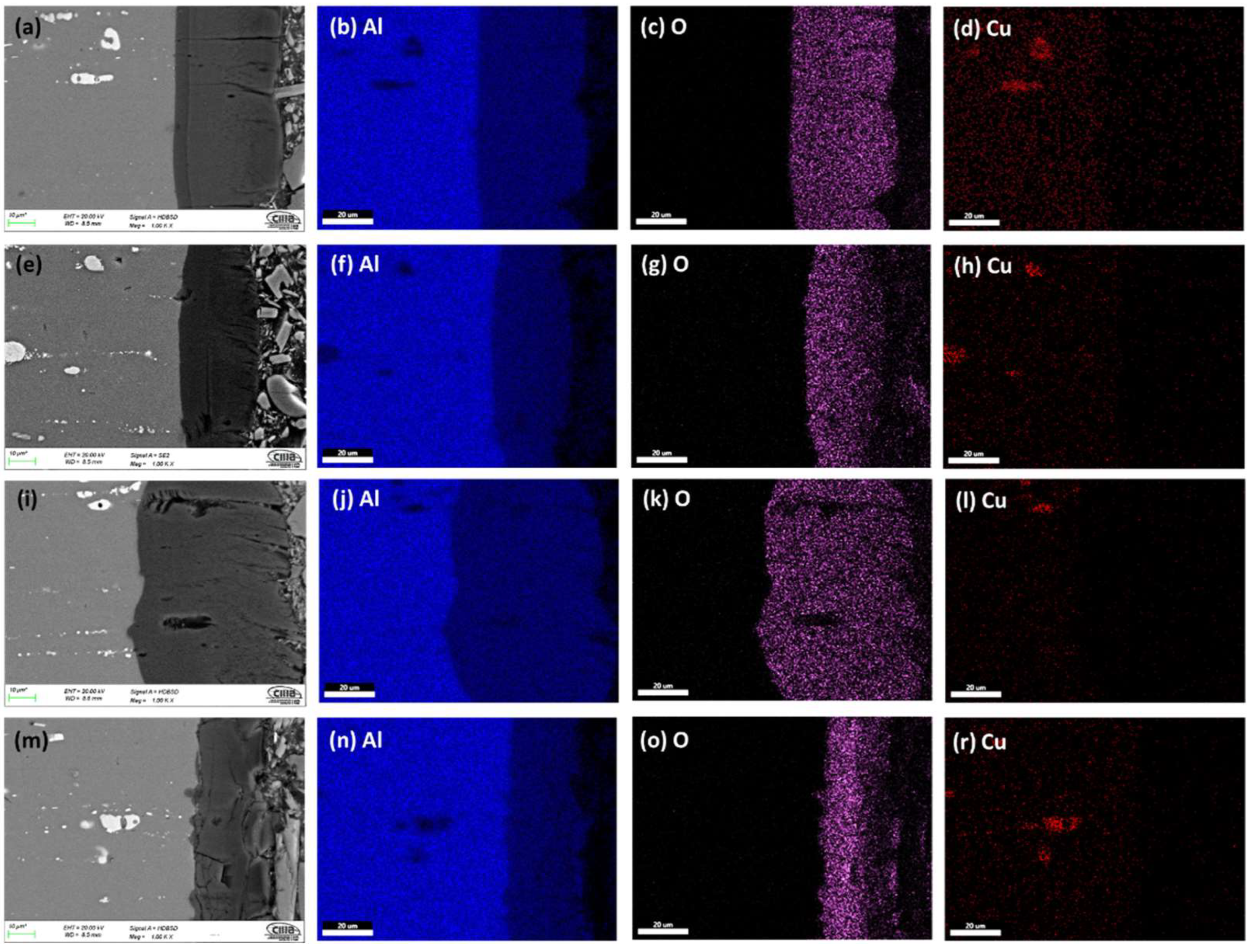
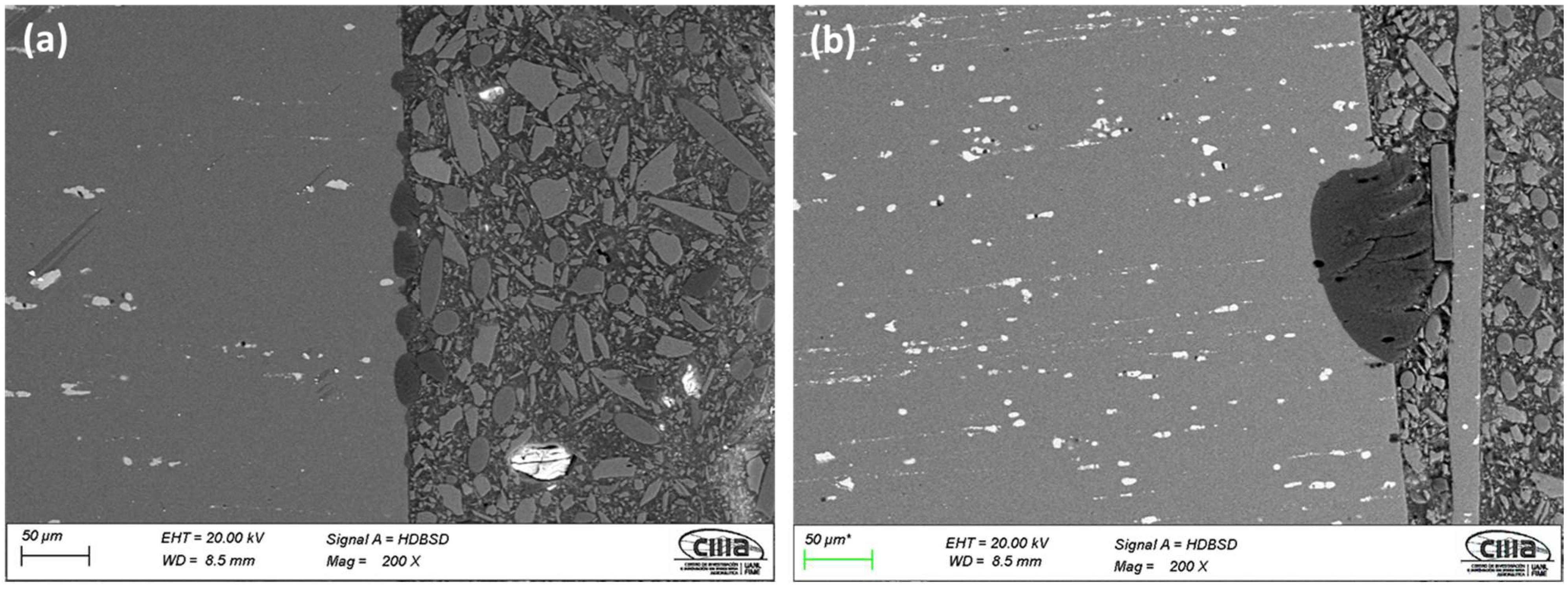
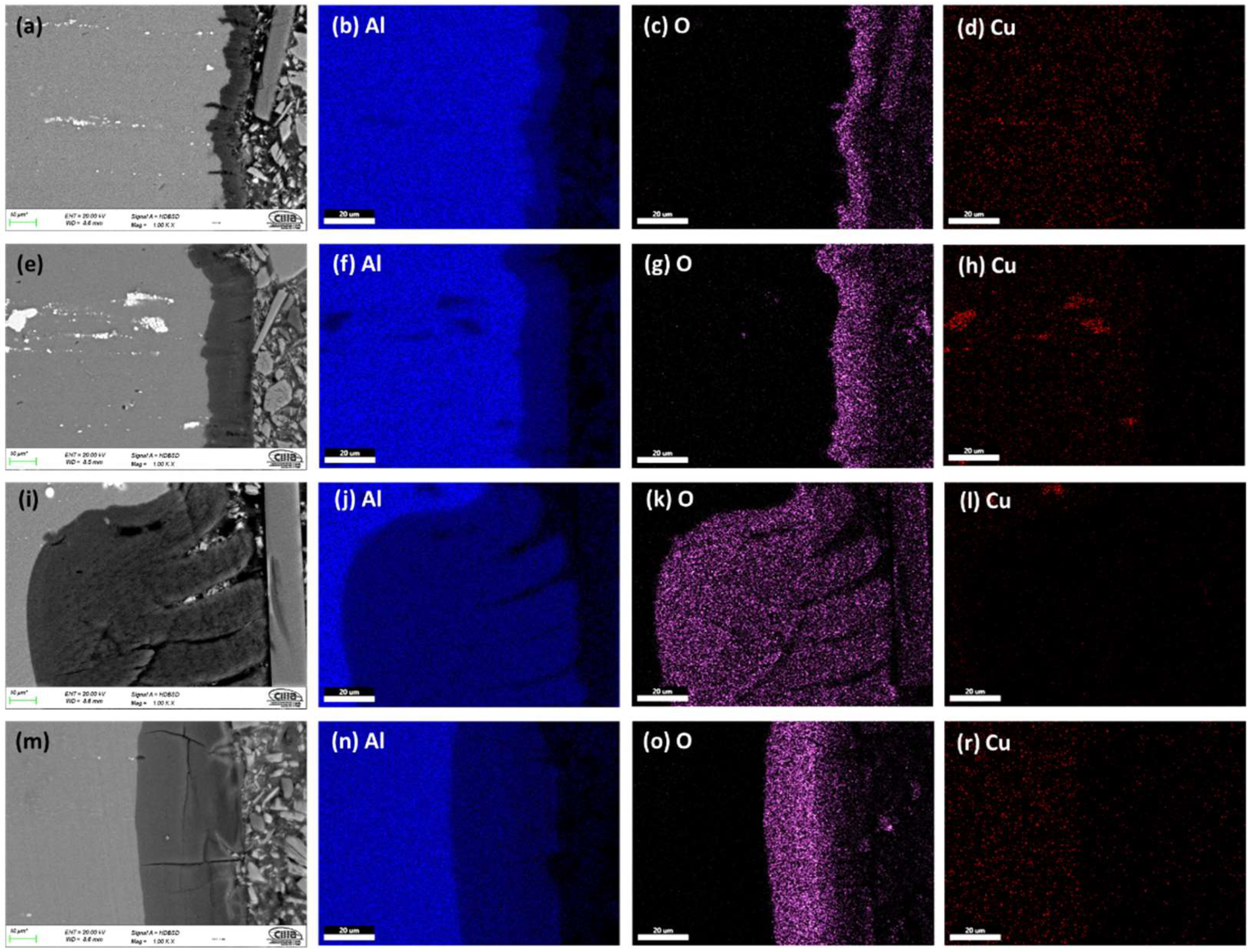
3.1.2. Morphology of Cross-Sections

Figure 3 and Figure 4 show the cross-section micrographs obtained by SEM and mapping of the chemical composition obtained by EDS of the anodized AA2024 alloy under different conditions. Figure 3a,e,i,m show that the anodized coating layer has porosity and cracking, which in some cases extends from the coatings surface to the base material. In sample 3 A S1M, there is also cracking. However, this does not reach the base material’s surface, as seen in Figure 3m.
The mapping of the chemical composition of the anodizing coating by EDS showed the aluminum content of the base material (substrate), in Figure 3b,f,j,n. A high concentration of oxygen in Figure 3c,g,k,o corresponds to the Al2O3 layer formed during the anodizing process. The white dots (see Figure 3a,e,i,m) correspond to Al2Cu precipitates typical of this type of alloy from the 2XXX series of aluminum alloys [49].
On the surface of the anodized samples, 4.5A C1M S5 and 4.5A C1M S10 with i = 4.5 A/dm2, porosity and cracking were not observed (Figure 4a,e). Porosity and cracking that could reach the substrate from the surface was observed in the samples 4.5A C1M and 4.5A S1M (Figure 4i,m). In Figure 4b,f,j,n, it can be observed by mapping of the chemical elements that have the presence of a higher concentration of aluminum in the base material, that the said concentration of aluminum decreases in the anodized coating. Figure 4c,g,k,o clearly show the formation of the Al2O3 layer derived from the type III hard anodizing process due to the high concentration of oxygen present. The Al2Cu precipitates can be seen in Figure 4d,h,l,r.
It can be seen in Figure 3e,m and Figure 4e,m that these coatings are homogeneous and show less cracking than the other samples manufactured with the two anodizing current densities 3 and 4.5 A/dm2. Samples 3A C1M and 4.5A C1M have areas without anodizing, as shown in Figure 5, at a lower magnification (200×). This is because some studies have found that alumina incorporated with citric acid takes a long time to deposit on the entire surface of the alumina. Once the pores nucleate and grow, the equilibrium self-organization process begins where the thickness of the barrier layer is reduced [50,51]. Additionally, it has been reported that to grow the anodic layers in electrolytes composed of organic acids such as citric and malonic, voltages greater than 350 V, temperatures below 0 °C, and anodizing times of up to 5 h are needed [52,53].

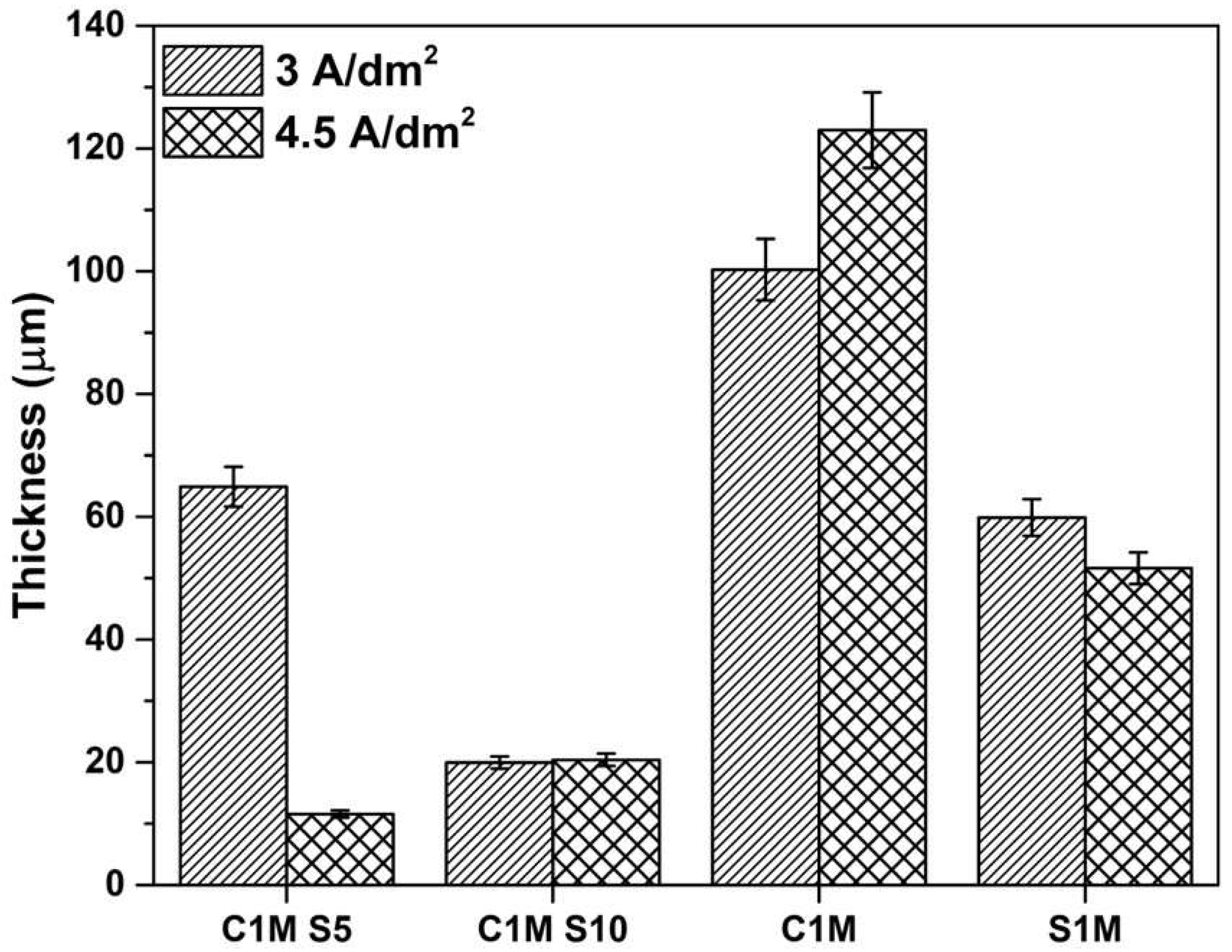
3.1.3. The Thickness of Anodized Samples of AA2024

Figure 6 shows the thickness obtained by SEM in cross-sectional anodized samples of AA2024 at i = 3 and 4.5 A/dm2 in different citric and sulfuric acid bath solutions. Anodized samples 3A C1M S5, 3A C1M S10, and 4.5A C1M S10 presented lower coating thicknesses, with 11.57, 19.95, and 20.41 µm. The rest of the coatings presented thicknesses greater than 50 µm, reaching 120 µm in some cases.
Samples 3A C1M and 4.5A C1M presented the greatest thicknesses. However these samples presented areas without anodizing (Figure 1c, Figure 2c, and Figure 5). Thin coatings form when an additive prevents the oxide coating from dissolving.
The thickness varies due to the applied current density as it affects the growth rate of oxidation films. Most of the thicknesses obtained in the various anodizing conditions allowed thicknesses greater than 12.7 m (minimum thickness required by MIL-A-8625 standard) [54].

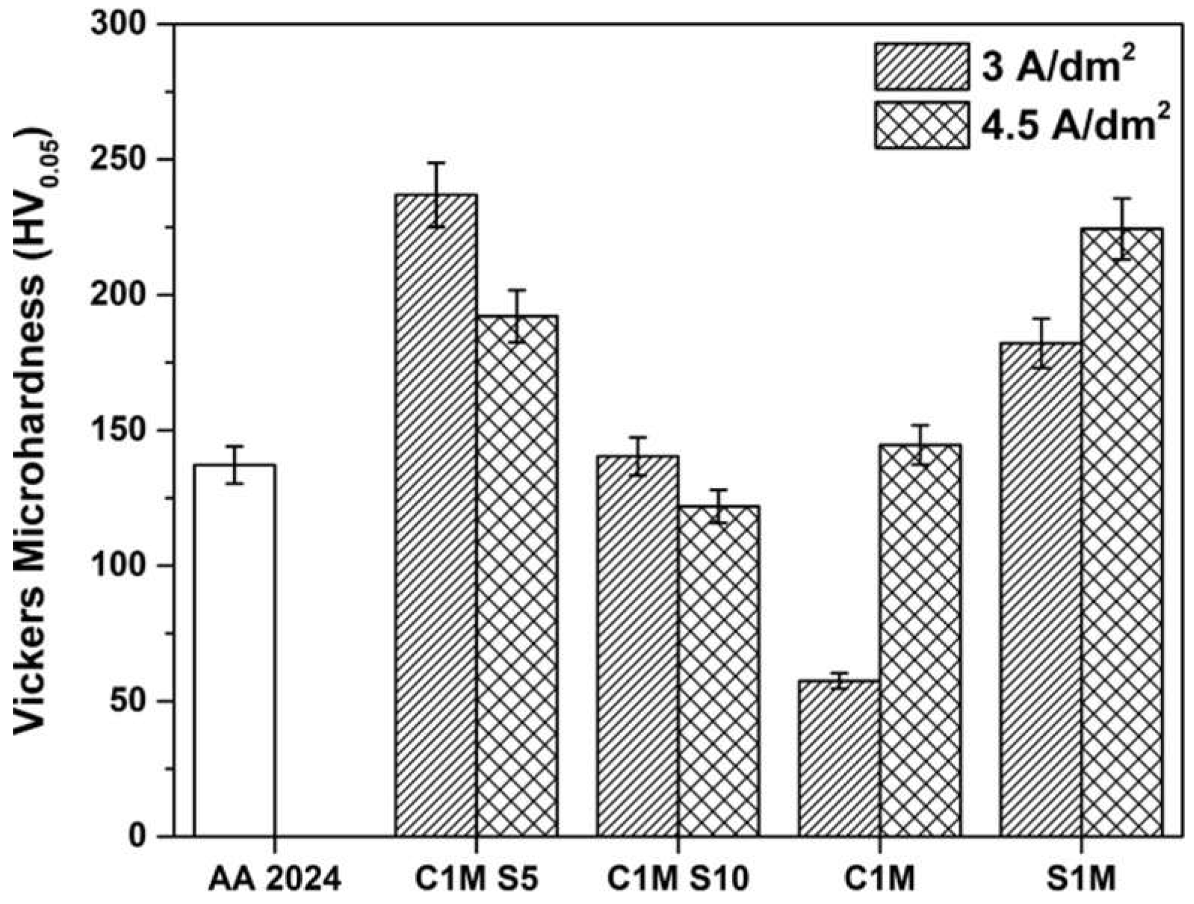
3.2. Vickers Microhardness Measurements

Vickers microhardness measurement results are presented in Figure 7. The highest microhardness values were found in samples 3A C1M S5, 4.5A C1M S5, and 4.5A S1M, with 236, 192, and 224 HV values, respectively. Samples 4.5A C1M S5, 3A C1M S10, 4.5A C1M, and 3A S1M presented higher hardness values than those shown by the base material AA2024 (137 HV). The samples with the lowest hardness were 3A C1M and 4.5A C1M S10, with values of 57 and 121 HV, respectively.
Hardness values from 150 to 300 HV in this work can be associated with the formation of Bayerite (Al2O3·3H2O) [55]. The low hardness values presented by samples 3A C1M and 4.5A C1M S10 may be associated with the high concentrations of baths, high temperatures, and prolonged processing times [54]. In this work, Vickers microhardness values higher than 300 HV were not obtained, which are common values for type III hard anodizing [1].

3.3. Electrochemical Techniques

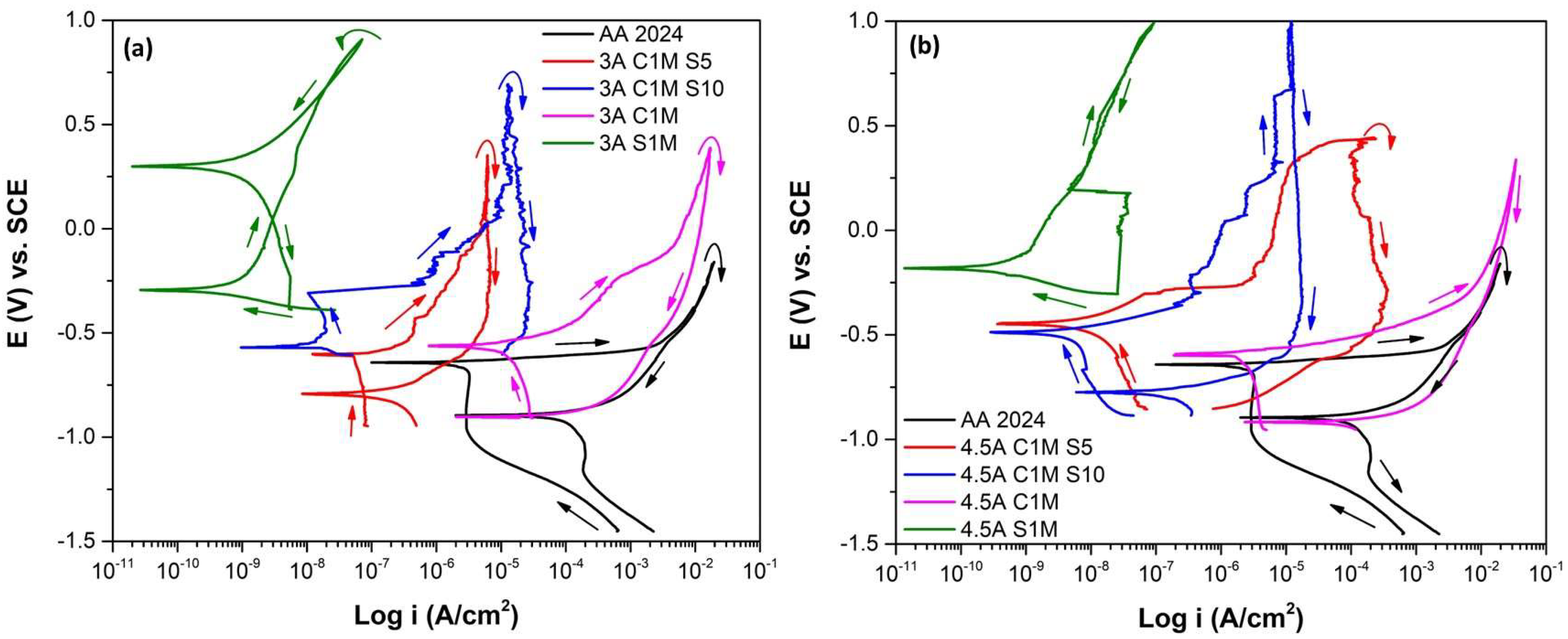
3.3.1. Cyclic Potentiodynamic Polarization

The CPP curves analyzed the corrosion process, which indicates the information of the anodic and cathodic branches and the hysteresis curve of the anodized samples.
Figure 8 shows the corrosion behavior of samples in different solutions with an i = 3 and 4.5 A/dm2 immersed in 3.5 wt. % NaCl solution. Figure 8a shows that AA2024 without anodizing has the lowest corrosion potential (Ecorr). All anodized samples showed more electropositive Ecorr. The 3A C1M sample presented an Ecorr = −0.600 mV, slightly higher than the potential of the AA2024 sample because it presented areas without anodizing, as observed in Figure 1c. Sample 3A S1M reached an Ecorr = −0.293 mV, the highest of the anodized samples with current density 3 A/dm2. Nobler values of Ecorr in anodized samples indicate less corrosion susceptibility [56,57]. Pitting potential (Epit) is the potential value at which the current increases and the pitting attack occurs.
Only sample 3A C1M S10 presented an Epit = −0.308 mV; in the rest of the samples, Epit did not appear. This behavior can be due to two reasons, the anodized surface is imperfect, or because of the breakdown of the oxide film and the appearance of pitting corrosion in the presence of aggressive ions such as Cl.
When there is an oxide film on the material surface prior to polarization, the pitting potential coincides with the corrosion potential for some materials. Because there is an intersection between the anodic branch (transpassive region) and the cathodic branch, the corrosion potential will be the same as the pitting potential [58]. The anodic to cathodic transition potential (EA–C) defines the necessary potential where the anodic current density varies with the cathodic current density. Only sample 3A S1M presented a nobler EA–C than Ecorr, which indicates that the sample is not susceptible to pitting corrosion. For samples 3A C1M S5, 3A C1M, and AA2024, the EA–C is more negative than Ecorr. Therefore, the protection of the oxide layer will persist [59,60]. In the sample, 3A C1M S10 EA–C was not present. The hysteresis loops were positive in most anodized samples with an i = 3 A/dm2, indicating localized corrosion. With this current density, only sample 3A S1M presented negative hysteresis; therefore, this sample has resistance to localized corrosion (Figure 8a). The difference in the icorr of sample 3A C1M S5 (1.57 × 10⁻⁷ A/cm2) and 3A S1M (1.36 × 10⁻¹⁰ A/cm2) is mainly due to the morphology and characteristics of the generated anode layer (see Table 2). On the one hand, sample 3A C1M S5 presents porosity and cracking that reaches from the surface of the coating to the substrate, which causes the electrolyte to enter the base material, while, in sample 3A S1M, the cracking occurs laterally, which prevents the penetration of the electrolyte into the substrate, as can be seen in Figure 3a,m.
Figure 8b shows CPP for samples with an i = 4.5 A/dm2 immersed in a 3.5 wt. % NaCl solution. All the anodized samples with an i = 4.5 A/dm2 in the different baths have a nobler corrosion potential than the non-anodized material. As with the 3A C1M sample, the 4.5A C1M sample presented an Ecorr = −0.593 mV, which is slightly higher than the potential of the AA2024 sample (Ecorr = −0.656 mV) since it also has areas without anodizing, which can be seen in Figure 2c.
The corrosion potential of the 4.5A S1M was the highest of all the samples (Ecorr = −0.180 mV), indicating less corrosion susceptibility. The 4.5A C1M S5 and 4.5A C1M S10 samples show an Epit = 0.334 and 0.034 mV, respectively, vs. SCE.
Epit present in some samples (3A C1M S5, 3A C1M S10, 3A C1M, 4.5A C1M S5, and 4.5A C1M S10) due to two reasons; the first is that the surface of the generated oxide is not perfect since there are some defects in coating, and the second could be due to the rupture of the oxide film and pitting corrosion appearance with the ions’ aggressive presence.
Sample 4.5A S1M is susceptible to pitting corrosion because it has a nobler EA–C than Ecorr. The protection provided by the oxide layer persists in samples 4.5A C1M S10 and 4.5A C1M since the EA-C is more negative than Ecorr [61,62]. In samples 4.5A C1M S5 and 4.5A S1M, EA–C did not appear. Localized corrosion occurs since the samples 4.5A C1M S5, 4.5A C1M S10, and 4.5A C1M show positive hysteresis loops; meanwhile, in the sample 4.5A S1M, there is generalized corrosion because its hysteresis loop is negative (Figure 8b).
The corrosion parameters obtained from the CPP (see Table 2), are Ecorr, Epit, EA–C, passivation current density (ipass), corrosion current density (icorr), and hysteresis type. The passivation current density was lower in samples 3A S1M and 4.5A S1M with values of 6.77 × 10⁻⁹ and 1.87 × 10⁻⁸ A/cm2, respectively; however, these samples were made in a conventional H2SO4 bath. However, samples 3A C1M S10, 4.5A C1M S5, and 4.5A C1M S10, also showed low ipass =1.38 × 10⁻⁸, 7.52 × 10⁻⁶, and 2.44 × 10⁻⁶ A/cm2, respectively; however, only sample 3A C1M S10 reached values as low as samples anodized in conventional H2SO4 solution. The values obtained from the ipass indicate that hard anodizing with citric acid solutions provides protection against corrosion that is not as effective as conventional anodizing in H2SO4 but is better than the material without anodizing treatment. This behavior has also been observed in anodized AA7075 alloys with other baths, and it is due to the barrier effect provided by the anodizing layer [63,64,65,66]. The icorr is directly related to the corrosion resistance of different materials. In this work, the lowest icorr was obtained in samples 3A S1M and 4.5A S1M, which were anodized in 1 M sulfuric acid solution.
The lower icorr appeared in samples with 10 mL/L of the sulfuric acid solution in the bath. In samples with 5 mL/L of sulfuric acid, galvanic pairs appeared. Finally, in samples 3A C1M and 4.5A C1M, in which the anodizing solution was completely composed of citric acid (192 g in 1 L of water), the higher icorr may be related to the formation of galvanic pairs between the anodized areas (cathodic sites) and non-anodized areas (anodic sites) (see Table 2).

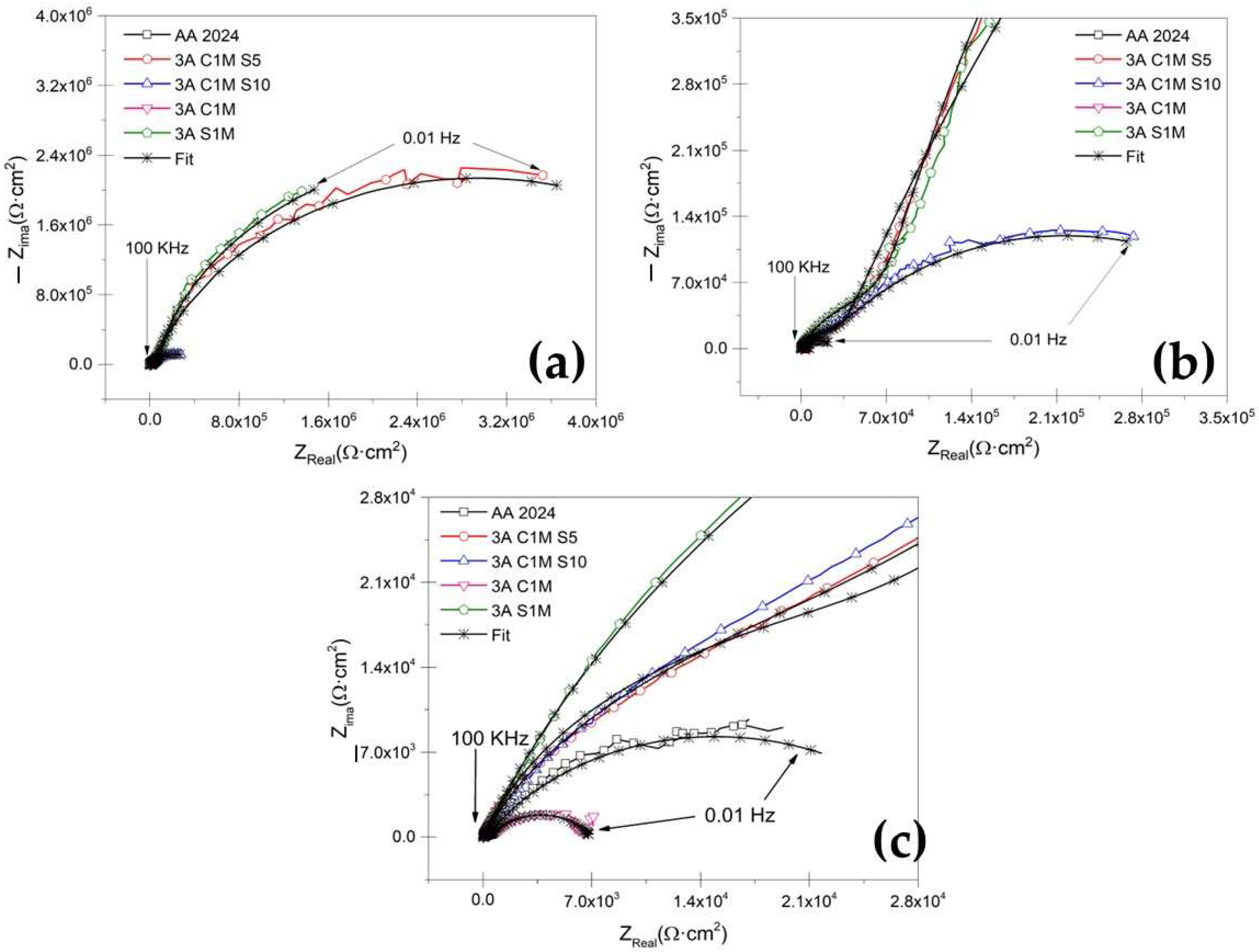
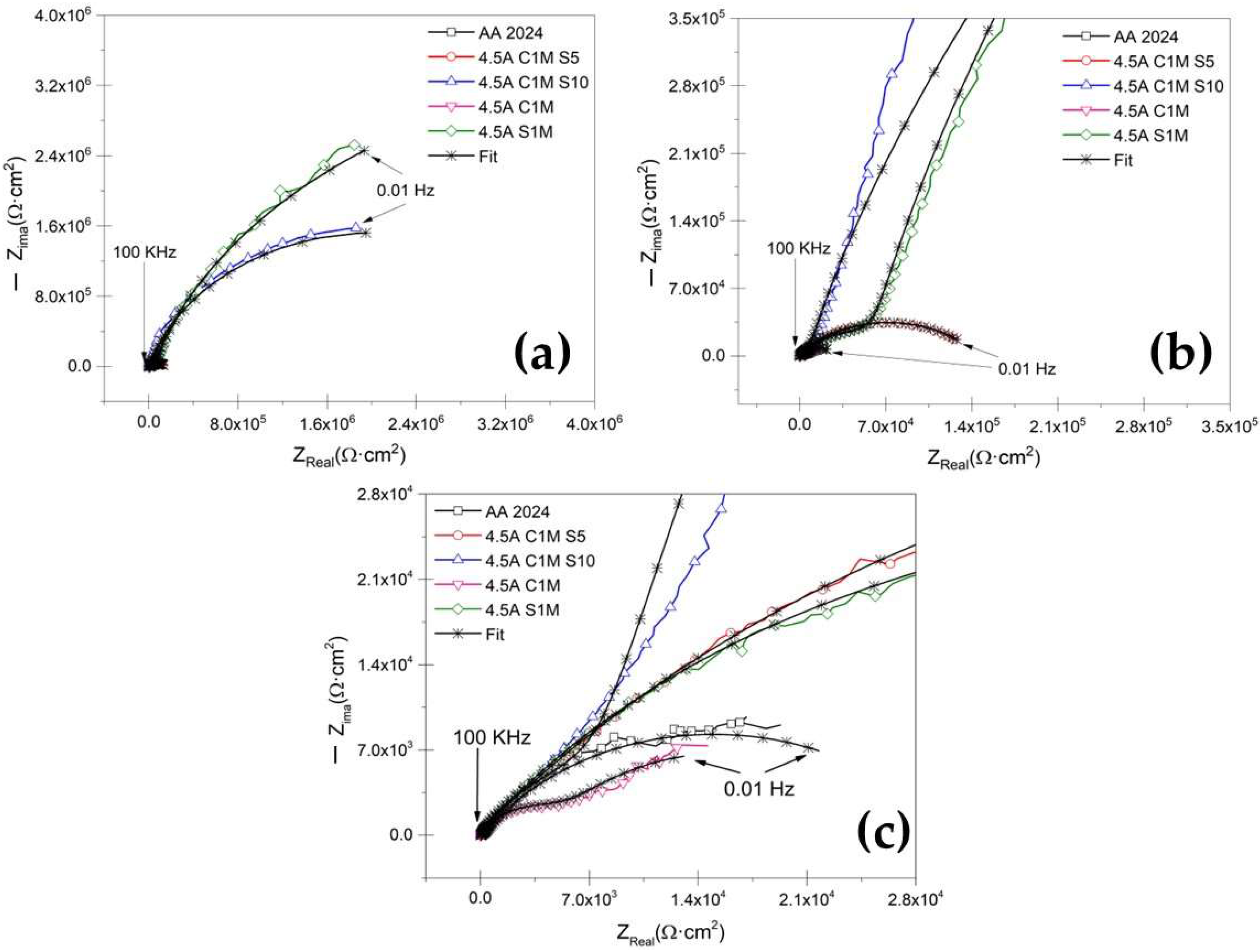
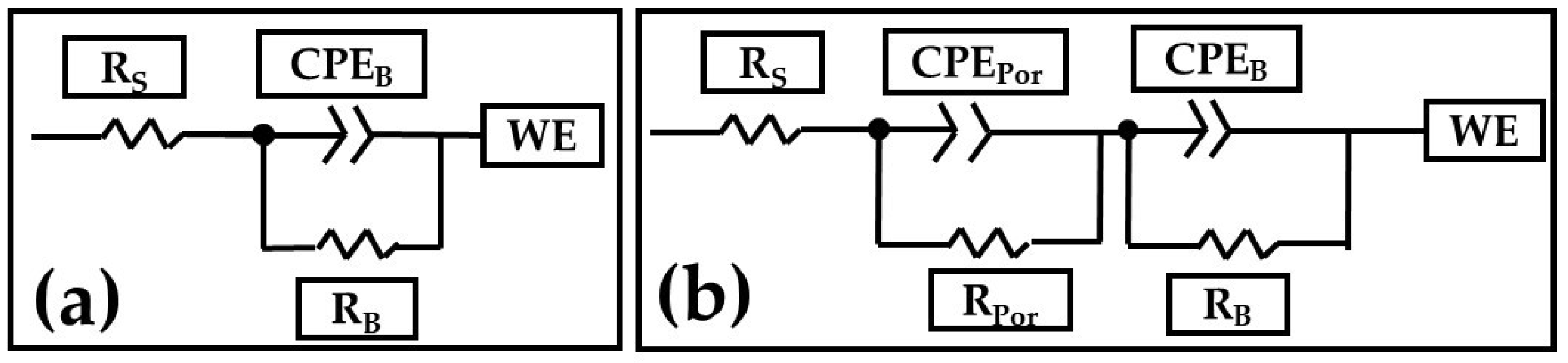
3.3.2. Electrochemical Impedance Spectroscopy Measurements

Figure 9a shows the Nyquist plot for anodized samples at i = 3 A/dm2 current density and different solutions immersed in 3.5 wt. % NaCl solution. The sample without anodizing treatment, AA2024, shows a characteristic behavior for aluminum alloys with an oxide layer naturally formed on the surface when in contact with oxygen (Figure 9c) [63,64,65,66]. For anodizing with the various mixtures of citric–sulfuric acid and a current density of 3 A/dm2 (Figure 9b,c), there is a high-frequency semicircle and a capacitive behavior at lower frequencies, which correspond to the characteristics of the porous layer and the barrier layer, respectively. In the zoom of Figure 9b,c, it can be seen that samples 3A C1M S10 and 4.5A C1M S5 present this same behavior.
Similarly, Figure 10a shows the Nyquist plot obtained for anodized samples in a mixture of citric–sulfuric acid and a current density of 4.5 A/dm2, exposed to the 3.5 wt. % NaCl electrolyte. In this case, the anodized samples with a current density of 4.5 A/dm2 in all the solutions composed of citric–sulfuric acid present the characteristics of the porous layer in the high-frequency range, while in the low-frequency range they often exhibit barrier layer properties. The Nyquist plot (Figure 10) shows that the anodized samples in citric acid solutions have a lower corrosion rate than the non-anodized AA2024 aluminum alloy because they have depressed semicircles at high frequency (1 × 10²–1 × 10⁴ Hz).
Figure 11a,b shows the equivalent electrical circuits (EEC) proposed to model the combination of kinetic processes from the EIS tests [67]. In this EEC, Rs is the solution resistance, RPor is the porous layer resistance, and RB is the barrier layer resistance. Furthermore, CPEPor is the constant phase element relative to the porous layer, CPEB is the barrier layer constant phase element, and WE is the working electrode. nPor and nB are the impedance exponents to the porous and barrier layers, respectively. The CPE can represent the roughness and heterogeneity of the porous and passive layers. The n coefficient can have several physical meanings at electrochemical interfaces, including surface roughness, corrosion products in the porous layer, and surface heterogeneity [68,69,70].
Table 3 presents the results obtained from the simulations using equivalent electrical circuits in Figure 11a,b. The variation in RSol is caused by coating morphology, which is linked to the surface charge and the electrochemical double layer [71]. The fit data of the EEC model that can be seen in Figure 9 and Figure 10 coincide largely with the experimental data. Therefore, in Table 3, the error presented by the simulations with EEC is less than <2.84 in most of the samples.
Additionally, the low values given by χ2 corroborate the accuracy of the proposed EEC model. They consider the porous layer resistance (RPor) of all the anodized samples with current densities 3 and 4.5 A/dm2. It can be established that this resistance also contributes to the corrosion resistance of anodized materials since samples 3A C1M S5, 3A C1M S10, 3A S1M, 4.5A C1M S10, and 4.5A S1M, RPor are greater than the resistance of the barrier layer resistance (RB) presented by the non-anodized material. For samples 3A C1M, 4.5A C1M S5, and 4.5A C1M, RPor was lower than the non-anodized material. These results show that the anodized material in a citric–sulfur acid solution protects against corrosion.
The higher values of CPEB for AA2024 un-anodized, 3A C1M, and 4.5A C1M are attributed to a thinner barrier layer: the values of CPEB are 1.27 × 10⁻⁴ F/cm2, 4.02 × 10⁻⁵ F/cm2, and 4.81 × 10⁻⁴ F/cm2, respectively. The results indicate that the thicknesses of these layers are more significant than the barrier layer formed naturally by the material un-anodized, AA2024 (see Table 3). According to some authors, the formed layer’s capacitance decreases as the formed coating’s thickness increases [72].
RB is related to charge transfer resistance (Rct), which is inversely proportional to the corrosion rate in anodized materials. Analyzing the values of RB of the samples 3A C1M, un-anodizing AA2024, and 4.5A C1M presented the lowest corrosion resistance in the evaluation medium with values of 6381 Ω·cm2, 13,920 Ω·cm2, and 19,478 Ω·cm2, respectively. In the samples 3A C1M S5, 3A C1M S10, 4.5A C1M S5, and 4.5A C1M S10, the RB values were 5.81 × 10⁶ Ω·cm2, 0.36 × 10⁶ Ω·cm2, 0.14 × 10⁶ Ω·cm2, and 4.11 × 10⁶ Ω·cm2, respectively. The results indicate that the anodized citric–sulfuric acid mixtures have better corrosion resistance in the 3.5 wt. % NaCl solution than the material without anodized AA2024. For the samples 3A S1M and 4.5A S1M, RB presented values of 6.20 × 10⁶ Ω·cm2 and 10.2 × 10⁶ Ω·cm2, respectively, providing excellent corrosion protection. It should be noted that this sample was created in a standard H2SO4 solution.

4. Discussion

All the anodized samples in the sulfuric and citric acid baths had superficial porosity, cracks, and practically the same morphology was presented for each solution regardless of the current density. SEM micrographs in Figure 1 and Figure 2 of the anodized AA2024 in citric–sulfuric acid show some cavities because of the copper intermetallic phase’s dissolution during anodizing in the different baths.
Cracks appeared on the anodic film formed on AA2024 due to extensive oxygen generation inside the film. The Al-Cu alloy contains the θ phase (Al2Cu), and the behavior of different second phases and the effect of the anodizing parameters on the properties of anodic films are critical for performing an effective anodizing process (see Figure 3 and Figure 4) [73]. Because of the high copper content, the AA2024 Al alloy had the lowest oxide thickness and number of cracks, which reduces the current efficiency (see Figure 6). The lower current efficiency is attributed to copper enrichment beneath the anodic film, copper oxidation, incorporation into the anodic film, and oxygen generation [74,75,76,77,78,79]. Aluminum combines with oxygen to form aluminum oxide during the anodizing process, which causes the oxide’s volume to grow and creates internal stress at the aluminum/oxide interface. When the oxide thickness and anodizing current density increase, so does this boundary stress. Additionally, when porosity decreases and the oxide barrier rises, higher interface stresses raise the anodic film’s hardness. However, when the material fails at the critical boundary stress, the stress releases and the fissures in the oxide film’s surface may be plainly seen. Additionally, the anodic voltage rises with current density, which results in a reduction in hardness because of the significant heat production. Finally, this compromised film structure causes the oxide’s hardness to decrease [80].
The coating is created during the anodizing process in the metal surface, and the current passes through the growing layer to reach the clean metal surface according to the coating thickness. The properties of the acid additives determine the electrolytes’ aggressiveness [79]. The literature has reported that working with low concentrations of sulfuric acid generates a dissolution of the anodizing layer [81]. The electrolyte is selected to carry out an anodizing process that significantly impacts the resulting anodic alumina film. Some film properties are determined by the type of electrolyte, its concentration, and its temperature [82,83,84]. One of the key factors affecting the oxide’s shape and chemistry is the electrolyte’s composition. One of the most prevalent additive mechanisms is the creation of complexes between organic molecules and aluminum. In this instance, the interaction of hard-ion carboxylates with trivalent aluminum cations results in easily formed complexes that are then absorbed into the anodic coating as insoluble metal soaps. The molecules are anticipated to protonate and become neutral in the solution without the inclination to migrate toward the anode since the pKa of carboxylic acids is higher than the pH value of the sulfuric acid baths [16,85]. The complexion additives form a thin film on the oxide surface protecting the metal [86].
Intermetallic particles strongly influence the morphology of the anodic layers in addition to their influence on oxide growth. According to their composition, copper-rich phases in the AA2024 Al alloy act as anodic or cathodic zones. S phases (Al2CuMg) serve as anodic zones, while θ phases (Al2Cu) serve as cathodic particles, causing pitting corrosion. A similar finding was made for the anodic layer formed on the 2214 Al alloy [87].
Copper intermetallic generates imperfections and fissures, and Vickers microhardness presents low values (see Figure 7). It has been demonstrated that Cu, Si, and Ni reduce the film’s hardness. [88]. When anodic oxides form in high-purity aluminum alloys, they are generally very dense and homogeneous, and the alloying elements can alter the properties of the layer formed, reducing corrosion resistance. The anodic oxides formed in aluminum alloys are not entirely composed of alumina due to the incorporation of alloying elements present in the composition of the substrate in the anodic layer and the incorporation of anions from the electrolyte. The effect of the alloying elements on the behavior and morphology of the anodized material depends on its nature. Based on this, the alloying elements can be classified into three categories. The first category is alloying elements with a lower Gibbs’ free energy of oxide formation compared to aluminum oxide (e.g., Mg, Li). The second group is made up of alloying elements that are more noble than aluminum and that oxidize during the anodizing process (e.g., Zn, Cu). Finally, the third group is made up of elements nobler than aluminum that do not undergo an oxidation process (e.g., Au) [89,90]. Since the most widely used alloys in the aerospace industry contain Mg, Cu, and Zn, attention must be paid to the effect of these elements on the oxide layer formed during anodizing.
Mg, being less noble than aluminum, oxidizes rapidly during the anodizing process, preferably forming MgO, since the volume occupied by MgO is less than the original volume occupied by elemental magnesium; the resulting oxide film is not continuous and tends to detach [91,92]. When Cu and Cu intermetallic are present on the aluminum substrate, the copper species are incorporated into the barrier-type anodic film as CuO units. In the first step, aluminum is preferentially oxidized at the oxide/alloy interface. The copper present, both in solid solution and in intermetallic phases such as the S phase (Al2CuMg) and θ phase (Al2Cu), does not oxidize. Therefore, it accumulates under the anodic film, leading to an area of copper enrichment. When a certain threshold of copper content is reached, the copper is oxidized and Al2O3, MgO, and CuO are simultaneously formed. Aluminum oxide, on the other hand, occupies a larger volume compared to elemental aluminum and, therefore, can fill the voids of the magnesium oxide, creating a continuous and well-adhered oxide film [93].
Cyclic potentiodynamic polarization curves (CPP) are used to describe and characterize anodic layers. After severe anodizing, Al alloys’ corrosion current densities fall considerably, and their polarization resistances rise (Figure 8 and Table 2). The intermetallic phases’ various types of flaws and the thickness of the oxide layer impact the anodic layer’s corrosion capabilities.
The corrosion potential of the anodized AA2024 alloy is more negative than samples anodized with citric–sulfuric acid, indicating enhanced anodic activity. The low corrosion resistance of anodized samples 3A C1M and 4.5A C1M is due to fewer cracks and oxide layer defects. This coincides with previous results where the oxide layer formed in an aluminum alloy 2618 was evaluated [94].
Anodized samples with current densities of 3 and 4.5 A/dm2 in various citric–sulfuric acid solutions exhibited acceptable electrochemical performance, which may be attributed to hard-ion carboxylate interactions with the Al3+ contained in the anodizing solution. This reaction results in intricate products being integrated into the surface, preventing corrosion [88]. The capacity of organic acids to adhere to metal surfaces and create a protective coating gives them their protective function [95].
The H2Cit, HCit2−, and Cit3− species are surface complexing ligands in the citric acid solution. The pH affects how much of these ligands is present in the solution (for example, HCit2− species predominated in citric acid solution pH 6). When citric acid solutions come into contact with an aluminum oxide surface, multiple surface coordination events occur, resulting in various aluminum–citrate and/or aluminum–hydroxo–citrate surface species. The nature and structure of these surface complexes are primarily unknown. However, several writers have documented the presence of two six-membered chelate ring structures on the surface [96,97]. Citrate anions are adsorbed on the oxide surface and integrated into the structure of the oxide layer as Al-citrate complexes during the anodic oxidation of aluminum in citric acid and/or citrate solutions. Equations (1) and (2) show the possible surface coordination reactions that can occur on the surface of aluminum oxide in citric acid solutions with a pH range of 3 to 6 [98,99].
Al   OH 2 + + HCit 2     AlHCit +     H 2 O
Al   OH + HCit 2     AlHCit +   OH
There are two distinct steps in the pore nucleation process of the anodization in citric acid: First, a rapid flat barrier-type alumina film is created by simultaneously depositing alumina at the oxide–electrolyte contact and forming it at the metal–oxide interface. The anodizing process current density creates an electric field, which causes O2−/OH ingress from oxide–electrolyte to metal–oxide surfaces and Al3+ egress from metal–oxide to oxide–electrolyte interfaces. Al–citrate complexes, which stabilize a specific quantity of Al3+, are present in the electrolyte.
Second, the electrolyte’s Al–citric complex slowly converts to citric acid-incorporated alumina and deposits it unevenly on barrier-type alumina, which causes an electric field concentration between protuberances and pore development. It should be noted that the protuberances created on the formed alumina surface because of the citric acid’s random and gradual incorporation of alumina are what cause the electric field to concentrate in certain areas. Alumina is quickly generated at the oxide–metal interface because of field-assisted dissolution occurring at the oxide–electrolyte surface, which thins the flat barrier layer that has been formed. To maintain the equifield field strength and cause the pore-forming, oxide growth at the metal–oxide interface with a scallop shape is controlled by the morphology at the oxide–electrolyte interface [52].
The EIS results indicate that the highest resistances found in citric–sulfuric acid solutions were in samples 3A C1M S5 and 4.5A C1M S10, with resistances of 5.82 × 10⁷ Ω·cm2 and 4.11 × 10⁷ Ω·cm2, respectively, which are excellent when compared with works published by other authors. Regarding the EIS results, resistances from 2 × 10⁵ Ω·cm2 to 10.7 × 10⁶ Ω·cm2 have been found in various previous works to show the hard anodizing of 6061 aluminum using a pulsed current [100]. In comparison, barrier layer resistances from hard anodizing aluminum alloy 7075 range from 6.18 × 10⁷ Ω·cm2 to 1.11 × 10⁹ Ω·cm2 [93]. In some additional works of hard anodizing with a pulse for anodized aluminum alloys of high purity, resistances of 8.53 × 10⁹ Ω·cm2 were discovered. In contrast, anodized aluminum alloy 2024 showed resistances in citric–sulfuric acid combinations between 1.38 and 2.44 × 10⁵ Ω·cm2 [101]. The morphology of porous anodic films on AA2024 alloy is significantly influenced by copper enrichment, the presence of copper and oxygen species in the film, the release of oxygen gas into the electrolyte, or a combination of these factors [48]. These results show that citric acid-based solutions can be used to hard anodize AA2024 aluminum alloys, resulting in resistance values that are on par with or higher than those published in the literature.
Numerous investigations have demonstrated that the barrier layer qualities are reflected in the low-frequency range, whereas the porous layer properties are reflected in the high and medium frequency ranges [102,103,104,105]. According to some writers, the anodic coating on aluminum comprises two layers: a very thin, compact barrier layer and a larger, porous layer, the latter of which comprises pores and walls made of hexagonal-shaped cells. The porous anodic film can be simulated using a variety of equivalent circuits, and these models have been effectively used to explain the characteristics of numerous materials’ porous layers and compact barriers [67,102,106,107,108,109,110,111].

5. Conclusions

  • Porous anodic alumina films were successfully produced under hard anodizing conditions on AA2024 alloy. Intermetallic phases in aluminum alloys influence the anodic layer growth rate and morphology. Oxide layers formed on AA2024 alloys with coarse intermetallic phases contained large cavities and surface defects.
  • Anodic films with porosity, cracks, and lateral porosity, commonly encountered during anodizing of AA2024 alloy, were obtained. In addition, oxidation of the second phase particles is achieved, and, as a result, its consumption generates cavities on the surface of the films and in the cross-section.
  • The thickness and Vickers microhardness obtained in the hard anodic coatings were low due to secondary phases rich in copper that prevent the film’s homogeneous growth. These secondary phases are associated with the generation of lateral porosity that also decreases properties. Lower thickness and microhardness are presented because of the formation of large cavities and defects induced by the activity of the Cu and Fe coarse intermetallic phases.
  • The cyclic potentiodynamic polarization technique indicated that higher Ecorr, and lower corrosion current densities (icorr), were presented in samples 3A CIM S5 and 4.5A C1M, representing that this sample provides more corrosion resistance than conventional sulfuric acid anodizing or the un-anodized alloy.
  • The EIS results indicate that hard-anodized coatings with citric–sulfuric acid showed resistance when exposed to a 3.5 wt. % NaCl solution for the samples 3A CIM S5 and 4.5A C1M S10.
  • Type III hard anodizing is possible with mixtures of citric–sulfuric acid solutions, which will present good mechanical properties and greater corrosion resistance than the material without anodizing.

Author Contributions

Conceptualization, J.C.M., F.A.C. and C.G.T.; methodology, J.C.M., E.G.M., E.M.-B., J.O.-C., M.L.-B. and M.Á.E.A.; data curation, J.C.M., L.D.L.-L., P.Z.-R. and D.N.-M.; formal analysis, J.C.M., F.A.C. and C.G.T.; writing—review and editing, F.A.C., J.C.M. and C.G.T. All authors have read and agreed to the published version of the manuscript.

Funding

This research was funded by the Mexican National Council for Science and Technology (CONACYT) of the projects A1-S-8882 and the Universidad Autónoma de Nuevo León (UANL).

Institutional Review Board Statement

Not applicable.

Informed Consent Statement

Not applicable.

Data Availability Statement

Not applicable.

Acknowledgments

The authors acknowledge The Academic Body UANL—CA-316 “Deterioration and integrity of composite materials” and the student Jesus Manuel Jaquez.

Conflicts of Interest

The authors declare no conflict of interest.

References

  1. Kwolek, P. Hard Anodic Coatings on Aluminum Alloys. Adv. Manuf. Sci. Technol. 2017, 41, 35–46. [Google Scholar]
  2. The history of aluminium industry. Available online: https://www.aluminiumleader.com/history/industry_history/ (accessed on 11 July 2022).
  3. Abdel-Salam, O.E.; Shoeib, M.A.; Elkilany, H.A. Characterization of the hard anodizing layers formed on 2014-T3 Al alloy, in sulphuric acid electrolyte containing sodium lignin sulphonate. Egypt. J. Petrol. 2017, 27, 497–504. [Google Scholar] [CrossRef]
  4. Mouritz, P.A. Aluminium alloys for aircraft structures. In Introduction to Aerospace Materials, 1st ed.; Mouritz, P.A., Ed.; Woodhead Publishing: Boston, MA, USA, 2012; Volume 1, pp. 173–201. [Google Scholar]
  5. Gloria, A.; Nontanari, R.; Richetta, M.; Varone, A. Alloys for Aeronautic Applications: State of the Art and Perspectives. Metals 2019, 9, 662. [Google Scholar] [CrossRef]
  6. Applications of 2024 Aluminum Alloy. Available online: https://www.howardprecision.com/applications-of-2024-aluminum-alloy/ (accessed on 11 July 2022).
  7. Huda, Z.; Taib, N.I.; Zaharinie, T. Characterization of 2024-T3: An aerospace aluminum alloy. Mater. Chem. Phys. 2009, 113, 515–517. [Google Scholar] [CrossRef]
  8. Technical Report TR-17. In Hard Anodizing of Aluminum Alloys and Its Effect on Bal Seal Performance; Bal Seal Engineering, Inc.: Lake Forest, CA, USA, 2016; Available online: https://www.balseal.com/wp-content/uploads/2019/06/Effects_Of_Hard_Anodizing_Aluminum_Alloys_On_Bal_SealTR_17.pdf (accessed on 10 September 2022).
  9. Renaud, A.; Paint, Y.; Lanzutti, A.; Bonnaud, L.; Fedrizzi, L.; Dubois, P.; Poorteman, M.; Oliver, M.G. Sealing porous anodic layers on AA2024-T3 with a low viscosity benzoxazine resin for corrosion protection in aeronautical applications. RSC Adv. 2019, 9, 16819–16830. [Google Scholar] [CrossRef]
  10. Safyari, M.; Hojo, T.; Moshtaghi, M. Effect of environmental relative humidity on hydrogen-induced mechanical degradation in an Al-Zn-Mg-Cu alloy. Vacuum 2021, 192, 110489. [Google Scholar] [CrossRef]
  11. Aerospace aluminum alloy 2024 for industrial application. Available online: http://www.aluminium-alloys.com/aerospace-aluminum-alloy-2024-for-industrial-application/ (accessed on 11 July 2022).
  12. 2024 Aluminum Alloy: Properties. Available online: https://www.gabrian.com/wp-content/uploads/2018/10/2024-Aluminum-Alloy-Properties.pdf (accessed on 12 July 2022).
  13. Cotell, C.M. Surface Engineering of Aluminum and Aluminum Alloys. In ASM Handbook; ASM International: Novelty, OH, USA, 1994; Volume 5, pp. 4–7. [Google Scholar]
  14. Montoya-Rangel, M.; de Garza-Montes, O.N.; Gaona-Tiburcio, C.; Colás, R.; Cabral-Miramontes, J.; Nieves-Mendoza, D.; Maldonado-Bandala, E.; Chacón-Nava, J.; Almeraya-Calderón, F. Electrochemical noise measurements of advanced high-strength steels in different solutions. Metals 2020, 10, 1232. [Google Scholar] [CrossRef]
  15. Martínez Viademonte, M.; Abrahami, S.T.; Hack, T.; Burchardt, M.; Terryn, H. A Review on Anodizing of Aerospace Aluminum Alloys for Corrosion Protection. Coatings 2020, 10, 1106. [Google Scholar] [CrossRef]
  16. Jalal, H.; Saound, Y.; Karabet, F. Effect of Organic Additives on AA6066 Anodization. J. Chem. Technol. Metall. 2019, 54, 447–453. [Google Scholar]
  17. Hitzig, J.; Jüttner, K.; Lorenz, W.J.; Paatsch, W. AC-Impedance Measurements on Porous Aluminium Oxide Films. Corros. Sci. 1984, 24, 945–952. [Google Scholar] [CrossRef]
  18. Gabe, D.R. Hard anodizing—What do we mean by hard? Met. Finish. 2002, 100, 52–58. [Google Scholar] [CrossRef]
  19. Memerifard, S.; Rahimipour, M.; Mobashrpour, I. Investigation of organic additives on voltage rate in Aluminum hard-anodizing process. Int. J. Bio-Inorg. Hybr. Nanomater 2017, 6, 59–63. [Google Scholar]
  20. Curioni, M.; Saenz de Miera, M.; Skeldon, P.; Thompson, G.E.; Ferguson, J. Macroscopic and Local Filming Behavior of AA2024 T3 Aluminum Alloy during Anodizing in Sulfuric Acid Electrolyte. J. Electrochem. Soc. 2008, 155, C387. [Google Scholar] [CrossRef]
  21. Boisier, G.; Pébère, N.; Druez, C.; Villarte, M.; Suel, S. FESEM and EIS Study of Sealed AA2024 T3 Anodized in Sulfuric Acid Electrolytes: Influence of Tartaric Acid. J. Electrochem. Soc. 2008, 155, C521–C529. [Google Scholar] [CrossRef]
  22. Torrescano Alvarez, J.M. Hard Anodic Films for Aluminum Alloys. Ph.D. Thesis, University of Manchester, Manchester, UK, 2018. [Google Scholar]
  23. Udochukwu Udochukwa, S.; Fernandes, F.A.O.; Pereira, A.B. The Sealing Step in Aluminum Anodizing: A Focus on Sustainable Strategies for Enhancing Both Energy Efficiency and Corrosion Resistance. Coatings 2020, 10, 226–282. [Google Scholar]
  24. Norek, M.; Wlodarski, M. Morphological and chemical characterization of highly ordered conical-pore anodic alumina prepared by multistep citric acid anodizing and chemical etching process. J. Porous Mater. 2018, 25, 45–53. [Google Scholar] [CrossRef]
  25. Shoshan, T.A.; De Kok, J.M.M.; Terryn, H.; Mol, J.M.C. Towards Cr(VI)-free anodization of aluminum alloys for aerospace adhesive bonding applications: A review. Front. Chem. Sci. Eng. 2017, 11, 465–482. [Google Scholar]
  26. Abd El-Hameed, A.M.; Abdel-Aziz, Y.A.; El-Tokhy, F.S. Anodic Coating Characteristics of Different Aluminum Alloys for Spacecraft Materials Applications. Mat. Sci. Appl. 2017, 8, 197–208. [Google Scholar] [CrossRef]
  27. Nakajima, D.; Kikuchi, T.; Natsui, S.; Suzuki, R.O. Growth behavior of anodic oxide formed by aluminum anodizing in glutaric and its derivative acid electrolytes. Appl. Surf. Sci. 2014, 321, 364–370. [Google Scholar] [CrossRef]
  28. Solmaz, R.; Kardas, G.; Yazici, B.; Erbil, M. Citric acid as natural corrosion inhibitor for aluminum protection. Corros. Eng. Sci. Technol. 2008, 43, 186–191. [Google Scholar] [CrossRef]
  29. ASTM E3-95; Standard Practice for Preparation of Metallographic Specimens. ASTM International: West Conshohocken, PA, USA, 1995.
  30. ASTM E407-07; Standard Practice for Microetching Metals and Alloys. ASTM International: West Conshohocken, PA, USA, 2011.
  31. Cabral-Miramontes, J.; Almeraya-Calderón, F.; López, F.E.; Lara Banda, M.; Olguín-Coca, J.; López-León, L.D.; Castañeda-Robles, I.; Alcalá, M.Á.E.; Zambrano-Robledo, P.; Gaona-Tiburcio, C. Citric Acid as an Alternative to Sulfuric Acid for the Hard-Anodizing of AA6061. Metals 2021, 11, 1838. [Google Scholar] [CrossRef]
  32. Franco, M.; Krishna, T.H.; Pillai, A.M.; Rajendra, A.; Sharma, A.K. A comparative study on the corrosion behavior of hard anodic coatings on aa 6061 obtained using dc and pulsed dc power sources. Acta Metall. Sin. Engl. Lett. 2013, 26, 647–656. [Google Scholar] [CrossRef]
  33. Cabral-Miramontes, J.A.; Barceinas-Sánchez, J.D.O.; Poblano-Salas, C.A.; Pedraza-Basulto, G.K.; Nieves-Mendoza, D.; Zambrano-Robledo, P.C.; Almeraya-Calderón, F.; Chacón-Nava, J.G. Corrosion Behavior of AISI 409Nb Stainless Steel Manufactured by Powder Metallurgy Exposed in H2SO4 and NaCl Solutions. Int. J. Electrochem. Sci. 2013, 8, 564–577. [Google Scholar]
  34. Cabral Miramontes, J.A.; Barceinas Sánchez, J.D.O.; Almeraya Calderón, F.; Martínez Villafañe, A.; Chacón Nava, J.G. Effect of Boron Additions on Sintering and Densification of a Ferritic Stainless Steel. J. Mater. Eng. Perform. 2010, 19, 880–884. [Google Scholar] [CrossRef]
  35. ASTM G61-86; Standard Test Method for Conducting Cyclic Potentiodynamic Polarization Measurements for Localized Corrosion Susceptibility of Iron-, Nickel-, or Cobalt-Based Alloys. ASTM International: West Conshohocken, PA, USA, 2018.
  36. Ramirez-Arteaga, A.M.; Gonzalez-Rodriguez, J.G.; Campillo, B.; Gaona-Tiburcio, C.; Dominguez-Patiño, G.; Leduc Lezama, L.; Chacon-Nava, J.G.; Neri-Flores, M.A.; Martinez-Villafañe, A. An Electrochemical Study of the Corrosion Behavior of a Dual Phase Steel in 0.5m H2SO4. Int. J. Electrochem. Sci. 2010, 5, 1786. [Google Scholar]
  37. Martínez-Villafañe, A.; Almeraya-Calderón, F.; Gaona-Tiburcio, C.; Gonzalez-Rodriguez, J.; Porcayo-Calderón, J. High-Temperature Degradation and Protection of Ferritic and Austenitic Steels in Steam Generators. J. Mater. Eng. Perform. 1998, 7, 108–113. [Google Scholar] [CrossRef]
  38. Lara-Banda, M.; Gaona-Tiburcio, C.; Zambrano-Robledo, P.; Delgado, E.M.; Cabral-Miramontes, J.A.; Nieves-Mendoza, D.; Maldonado-Bandala, E.; Estupiñan-López, F.; Chacón-Nava, J.G.; Almeraya-Calderón, F. Alternative to Nitric Acid Passivation of 15-5 and 17-4PH Stainless Steel Using Electrochemical Techniques. Materials 2020, 13, 2836. [Google Scholar] [CrossRef]
  39. Almeraya- Calderon, F.; Montoya-R., M.; Garza-Montes-de-Oca, N.; Castorena, J.; Estupiñan-Lopez, F.; Miramontes, J.; Gaona-Tiburcio, C. Corrosion behavior of multilayer coatings deposited by PVD on Inconel 718 in Chloride and Sulphuric Acid solutions. Int. J. Electrochem. Sci. 2019, 14, 9596–9609. [Google Scholar] [CrossRef]
  40. Jáquez-Muñoz, J.M.; Gaona-Tiburcio, C.; Chacón-Nava, J.; Cabral-Miramontes, J.; Nieves-Mendoza, D.; Maldonado-Bandala, E.; Delgado, A.D.; Flores-De los Rios, J.P.; Bocchetta, P.; Almeraya-Calderón, F. Electrochemical corrosion of titanium and titanium alloys anodized in H2SO4 and H3PO4 solutions. Coatings 2022, 12, 325. [Google Scholar] [CrossRef]
  41. Huang, Y.L.; Shih, H.; Huang, H.; Daugherty, J.; Wu, S.; Ramanathan, S.; Chang, C.; Mansfeld, F. Evaluation of the corrosion resistance of anodized aluminum 6061 using electrochemical impedance spectroscopy (EIS). Corros. Sci. 2008, 50, 3569–3575. [Google Scholar] [CrossRef]
  42. Zuo, Y.; Zhao, P.H.; Zhao, J.M. The influences of sealing methods on corrosion behavior of anodized aluminum alloys in NaCl solutions. Surf. Coat. Technol. 2003, 166, 237–242. [Google Scholar] [CrossRef]
  43. Suay, J.J.; Gimenez, E.; Rodriguez, T.; Habbib, K.; Saura, J.J. Characterization of anodized and sealed aluminium by EIS. Corros. Sci. 2003, 45, 611–624. [Google Scholar] [CrossRef]
  44. ASTM G106-15; Standard Practice for Verification of Algorithm and Equipment for Electrochemical Impedance Measurements. ASTM International: West Conshohocken, PA, USA, 2015.
  45. Cabral-Miramontes, J.A.; Bastidas, D.M.; Baltazar, M.A.; Zambrano-Robledo, P.; Bastidas, J.M.; Almeraya-Calderón, F.M.; Gaona-Tiburcio, C. Corrosion behavior of Zn-TiO2, and Zn-ZnO Electrodeposited Coating in 3.5% NaCl Solution. Int. J. Electrochem. Sci. 2019, 14, 4226–4239. [Google Scholar] [CrossRef]
  46. Maldonado-Bandala, E.; Jiménez-Quero, V.; Olguin-Coca, J.; Lizarraga, L.G.; Baltazar-Zamora, M.A.; Ortiz, C.A.; Almeraya, C.F.; Zambrano, R.P.; Gaona-Tiburcio, C. Electrochemical Characterization of Modified Concretes with Sugar Cane Bagasse Ash. Int. J. Electrochem. Sci. 2011, 6, 4915–4926. [Google Scholar]
  47. Cabral-Miramontes, J.; Gaona-Tiburcio, C.; Estupinán-López, F.; Lara-Banda, M.; Zambrano-Robledo, P.; Nieves-Mendoza, D.; Maldonado-Bandala, E.; Chacón-Nava, J.; Almeraya-Calderón, F. Corrosion Resistance of Hard Coat Anodized AA 6061 in Citric–Sulfuric Solutions. Coatings 2020, 10, 601. [Google Scholar] [CrossRef]
  48. Samaniego-Gámez, P.; Almeraya-Calderón, F.; Martin, U.; Ress, J.; Gaona-Tiburcio, C.; Silva-Vidaurri, L.; Cabral-Miramontes, J.; Bastidas, J.M.; Chacón-Nava, J.G.; Bastidas, D.M. Efecto del tratamiento de sellado en el comportamiento frente a corrosión de la aleación anodizada de aluminio-litio AA2099. Rev. Met. 2020, 56, e180. [Google Scholar] [CrossRef]
  49. Iglesias-Rubianes, L.; Garcia-Vergara, S.J.; Skeldon, P.; Thompson, G.E.; Ferguson, J.; Beneke, M. Cyclic oxidation processes during anodizing of Al-Cu alloys. Electrochim. Acta 2007, 52, 7148–7157. [Google Scholar] [CrossRef]
  50. Ma, Y.; Wen, Y.; Li, J.; Li, Y.; Zhang, Z.; Feng, C.; Sun, R. Fabrication of self-ordered alumina films with large interpore distance by Janus anodization in citric acid. Sci. Rep. 2016, 6, 39165. [Google Scholar] [CrossRef] [Green Version]
  51. Li, J.; Zhang, Z.; Li, Y.; Ma, Y.; Chen, L.; Zhang, Z.; Sun, R. Self-Organization process of aluminum oxide during hard anodization. Electrochim. Acta 2016, 213, 14–20. [Google Scholar] [CrossRef]
  52. Ma, Y.; Wen, Y.; Li, J.; Lu, J.; Li, Y.; Yang, Y.; Feng, C.; Hao, C.; Zhang, Z.; Hu, J.; et al. Pore nucleation mechanism of self-ordered alumina with large period in stable anodization in citric acid. J. Electrochem. Soc. 2018, 165, E311–E317. [Google Scholar] [CrossRef]
  53. Tabesh, S.; Davar, F.; Loghman-Estarki, M.R. The effects of chelating agent type on the morphology and phase evolutions of alumina nanostructures. Ceram. Int. 2017, 43, 10247. [Google Scholar] [CrossRef]
  54. MIL-A-8625F; Anodic Coatings for Aluminum and Aluminum Alloys. Departments and Agencies of the Department of Defense: Washington, VA, USA, 1993; pp. 1–19.
  55. Thomas, R.W. Hard Anodizing of Aluminum; Brace, A.W., Ed.; Technicopy Ltd.: Stonehouse, UK, 1987; pp. 1–7. [Google Scholar]
  56. Lerner, L.M. Hard anodizing of aerospace aluminium alloys. Trans. Inst. Met. Finish. 2010, 88, 21–24. [Google Scholar] [CrossRef]
  57. Wang, L.W.; Tian, H.Y.; Gao, H.; Xie, F.Z.; Zhao, K.; Cui, Z.Y. Electrochemical and XPS analytical investigation of the accelerative effect of bicarbonate/carbonate ions on AISI 304 in alkaline environment. Appl. Surf. Sci. 2019, 492, 792–807. [Google Scholar] [CrossRef]
  58. Yang, Y.J.; Zhang, Z.P.; Jin, Z.S.; Sun, W.C.; Xia, C.Q.; Ma, M.Z.; Zhang, X.Y.; Li, G.; Liu, R.P. A study on the corrosion behavior of the in-situ Ti-based bulk metallic glass matrix composites in acid solutions. J. Alloy. Compd. 2019, 782, 927–935. [Google Scholar] [CrossRef]
  59. Silverman, D.C. Practical Corrosion prediction using electrochemical techniques. In Uhlig’s Corrosion Handbook, 3rd ed.; Winston Revie, R., Ed.; John Wiley & Son, Inc.: Hoboken, NJ, USA, 2011; pp. 1129–1166. [Google Scholar]
  60. Silverman, D.C. Tutorial on Cyclic Potentiodynamic Polarization Technique. CORROSION 98, San Diego, CA, USA, 22–27 March 1998; 1998. [Google Scholar]
  61. Gaona-Tiburcio, C.; Almeraya-Calderón, F.; Chacon-Nava, J.; Matutes-Aquino, A.M.; Martinez-Villafañe, A. Electrochemical response of permanent magnets in different solutions. J. Alloys Compd. 2004, 369, 78–80. [Google Scholar] [CrossRef]
  62. Huang, Y.; Esra, K.; Mansfeld, F. Evaluation of the corrosion resistance of anodizing aluminum samples using electrochemical impedance spectroscopy. In Proceedings of the Annual Graduate Student Research Symposium, Los Angeles, CA, USA, 13 February 2007. [Google Scholar]
  63. Dzhurinskiy, D.V.; Dautov, S.S.; Shornikov, P.G.; Akhatov, I.S. Surface Modification of Aluminum 6061-O Alloy by Plasma Electrolytic Oxidation to Improve Corrosion Resistance Properties. Coatings 2021, 11, 4. [Google Scholar] [CrossRef]
  64. Feliu, S.J. Electrochemical impedance spectroscopy for the measurement of the corrosion rate of magnesium alloys: Brief review and challenges. Metals 2020, 10, 775. [Google Scholar] [CrossRef]
  65. Hoar, T.P.; Wood, G.C. The sealing of porous anodic oxide films on aluminium. Electrochim. Acta 1962, 7, 333–353. [Google Scholar] [CrossRef]
  66. Samaniego-Gámez, P.O.; Almeraya-Calderon, F.; Maldonado-Bandala, E.; Cabral-Miramontes, J.; Nieves-Mendoza, D.; Olguin-Coca, J.; Lopez-Leon, L.D.; Silva Vidaurri, L.G.; Zambrano-Robledo, P.; Gaona-Tiburcio, C. Corrosion Behavior of AA2055 Aluminum-Lithium Alloys Anodized in the Presence of Sulfuric Acid Solution. Coatings 2021, 11, 1278. [Google Scholar] [CrossRef]
  67. Kwolek, P.; Krupa, K.; Obłój, A.; Kocurek, P.; Wierzbinka, M.; Sieniawski, J. Tribological Properties of the Oxide Coatings Produced onto 6061-T6 Aluminum Alloy in the Hard Anodizing Process. J. Mater. Eng. Perform. 2018, 27, 3268–3275. [Google Scholar] [CrossRef]
  68. Samaniego-Gámez, O.; Almeraya-Calderón, F.; Chacón-Nava, J.; Maldonado-Bandala, E.; Nieves-Mendoza, D.; Flores-De los Rios, J.P.; Jáquez-Muñoz, J.M.; Delgado, A.D.; Gaona-Tiburcio, C. Corrosion Behavior of Passivated CUSTOM450 and AM350 Stainless Steels For Aeronautical Applications. Metals 2022, 12, 666. [Google Scholar] [CrossRef]
  69. Cesiulis, H.; Tsyntsaru, N.; Ramanavicius, A.; Ragoisha, G. The Study of Thin Films by Electrochemical I. In Nanostructures and Thin Films for Multifunctional Applications; Tiginyanu, I., Topala, P., Ursaki, V., Eds.; Nanoscience and Technology; Springer: Berlin/Heidelberg, Germany, 2016. [Google Scholar]
  70. Kramer, G.R.; Mendez, C.M.; Ares, A.E. Evaluation of corrosion resistance of aluminum-based alloys in bioethanol produced in Misiones. Proc. Mat. Sci. 2015, 9, 341–349. [Google Scholar] [CrossRef]
  71. Elkilany, H.A.; Shoeib, M.A.; Abdel-Salam, O.E. Influence of hard anodizing on the mechanical and corrosion properties of different aluminum alloys. Metallogr. Microstruct. Anal. 2019, 8, 861–879. [Google Scholar] [CrossRef]
  72. Habazaki, H.; Shimizu, K.; Paez, M.A.; Skeldon, P.; Thompson, G.E.; Wood, G.C.; Xhou, X. Oxidation of copper and mobility of copper ions during anodizing of an Al–1.5 wt.% Cu alloy. Surf. Interface Anal. 1995, 23, 892–898. [Google Scholar] [CrossRef]
  73. Vukmirovic, M.B.; Dimitrov, N.; Sieradzki, K. Dealloying and corrosion of Al alloy 2024 T3. J. Electrochem. Soc. 2002, 149, 428–439. [Google Scholar] [CrossRef]
  74. Buchheit, R.G.; Martinez, M.A.; Montes, L.P. Evidence for Cu ions formation by dissolution and dealloying of Al2CuMg intermetallic compound in rotating disk. J. Electrochem. Soc. 2000, 147, 119–124. [Google Scholar] [CrossRef]
  75. Moutarlier, V.; Gigandet, M.P.; Pagettia, J.; Normand, B. An electrochemical approach to the anodic oxidation of Al 2024 alloy in sulfuric acid containing inhibitors. Surf. Coat. Technol. 2002, 161, 267–274. [Google Scholar] [CrossRef]
  76. Hashimoto, T.; Zhou, X.; Skeldon, P.; Thompson, G.E. Structure of the Copper–enriched layer introduced by anodic oxidation of copper-containing aluminum Alloy. Electrochim. Acta 2015, 179, 394–401. [Google Scholar] [CrossRef]
  77. Hashimoto, T.; Zhang, X.; Zhou, X.; Skeldon, P.; Haigh, S.J.; Thompson, G.E. Investigation of dealloying of S phase (Al2CuMg) in AA 2024-T3 aluminum alloy using high-resolution 2D and 3D electron imaging. Corros. Sci. 2016, 103, 157–164. [Google Scholar] [CrossRef]
  78. Snogan, F.; Blanc, C.; Mankowski, G.; Pebere, N. Characterisation of sealed anodic films on 7050 T74 and 2214 T6 aluminum alloys. Surf. Coat. Technol. 2002, 154, 94–103. [Google Scholar] [CrossRef]
  79. Fratila-Apachitei, L.E.; Tichelaar, F.D.; Thompson, G.E.; Terryn, H.; Skeldon, P.; Duszczyk, J.; Katgerman, L. A transmission electron microscopy study of hard anodic oxide layers on AlSi(Cu) alloys. Electrochim. Acta. 2004, 49, 3169–3177. [Google Scholar] [CrossRef]
  80. Cheng, T.C.; Chou, C.C. The electrical and mechanical properties of porous anodic 6061-T6 aluminum alloy oxide film. J. Nanomat. 2015, 2015, 141. [Google Scholar] [CrossRef]
  81. Koczera, A.E. The Effects of Carboxylic Acids in Aluminum Anodizing. Ph.D. Thesis, University of New Hampshire, Durham, NH, USA, 2017. [Google Scholar]
  82. Peng, L.; Li, M. Improved technology for hard anodizing dissolution of aluminum alloy part. Open Mat. Sci. J. 2015, 9, 82–85. [Google Scholar] [CrossRef]
  83. Chu, S.Z.; Wada, K.; Inoue, S.; Isogai, M.; Yasumori, A. Fabrication of ideally ordered nanoporous alumina films and integrated alumina nanotubule arrays by high-field anodization. Adv. Mater. 2005, 17, 2115–2119. [Google Scholar] [CrossRef]
  84. Schwirn, K.; Lee, W.; Hillebrand, R.; Steinhart, M.; Nielsch, K.; Gösele, U. Self-ordered anodic aluminum oxide formed by H2SO4 hard anodization. ACS Nano 2008, 2, 302–310. [Google Scholar] [CrossRef]
  85. Cao, C.; Zhang, G.; Ye, J.; Hua, R.; Sun, Z.; Cui, J. Fast growth of self-aligned titania nanotube arrays with excellent transient photoelectric response. Electrochim. Acta. 2016, 211, 552–560. [Google Scholar] [CrossRef]
  86. Stępniowski, W.J.; Norek, M.; Michalska-Domańska, M.; Bojar, Z. Ultra-small nanopores obtained by self-organized anodization of aluminum in oxalic acid at low voltages. Mater. Lett. 2013, 111, 20–23. [Google Scholar] [CrossRef]
  87. Noh, K.; Brammer, K.; Kim, H.; Jung, S.; Seong, T.; Jin, S. Highly self-assembled nanotubular aluminum oxide by hard anodization. J. Mater. Res. 2011, 26, 186–193. [Google Scholar] [CrossRef]
  88. Dimogerontakis, T.; Kaplanoglou, L.; Kaplanoglou, I. Oxygen evolution during the formation of barrier type anodic film on 2024-T3 aluminium alloy. Corros. Sci. 1998, 40, 1939–1951. [Google Scholar] [CrossRef]
  89. Habazaki, H.; Shimizu, K.; Skeldon, P.; Thompson, G.E.; Wood, G.C. the composition of the alloy/film interface during anodic oxidation of Al-W alloys. J. Electrochem. Soc. 1996, 143, 2465–2470. [Google Scholar] [CrossRef]
  90. Habazaki, H.; Shimizu, K.; Skeldon, P.; Thompson, G.E.; Wood, G.C.; Zhou, X. Effects of alloying elements in anodizing of aluminium. Trans IMF 1997, 75, 18–23. [Google Scholar] [CrossRef]
  91. Habazaki, H.; Zhou, X.; Shimizu, K.; Skeldon, P.; Thompson, G.E.; Wood, G.C. Mobility of copper ions in anodic alumina films. Electrochim. Acta. 1997, 42, 2627–2635. [Google Scholar] [CrossRef]
  92. Torrescano-Alvarez, J.M.; Curioni, M.; Habazaki, H.; Hashimoto, T.; Skeldon, P.; Zhou, X. Incorporation of alloying elements into porous anodic films on aluminium alloys: The role of cell diameter. Electrochim. Acta. 2019, 296, 783–789. [Google Scholar] [CrossRef]
  93. Michalska-Domańska, M.; Norek, M.; Stępniowski, W.J.; Budner, B. Fabrication of high quality anodic aluminum oxide (AAO) on low purity aluminum-A comparative study with the AAO produced on high purity aluminum. Electrochim. Acta. 2013, 105, 424–432. [Google Scholar] [CrossRef]
  94. Zajączkowska, L.; Siemiaszko, D.; Norek, M. Towards self-organized anodization of aluminum in malic acid solutions-new aspects of anodization in the organic acid. Materials 2020, 13, 3899. [Google Scholar] [CrossRef] [PubMed]
  95. Jalal, H.; Hussein, K.; Karabet, F.; Saound, Y. Study of the effect mechanism of organic additives on the aluminum alloy 6066 anodization. J. Miner. Met. Mater. Eng. 2019, 5, 73–81. [Google Scholar]
  96. Sposito, G. The Environmental Chemistry of Aluminum, 2nd ed.; CRC Press: Boca Raton, FL, USA, 1996; pp. 173–174, 303–305. [Google Scholar]
  97. Hidber, P.C.; Graule, T.J.; Gauckler, L.J. Citric Acid—A Dispersant for Aqueous Alumina Suspensions. J. Am. Ceram. Soc. 1996, 79, 1857–1867. [Google Scholar] [CrossRef]
  98. Ban, C.L.; He, Y.D.; Xin, S. Effect of citric acid on microstructure and electrochemical characteristics of high voltage anodized alumina film formed on etched Al Foils. Trans. Nonferrous Met. Soc. China. 2011, 21, 133–138. [Google Scholar] [CrossRef]
  99. Xiangfeng, M.; Guoying, W.; Hongliang, G.; Yundan, Y.; Ying, C.; Dettinger, H. Anodization for 2024 Al Alloy from Sulfuric-Citric Acid and Anticorrosion Performance of Anodization Films. Int. J. Electrochem. Sci. 2013, 8, 10660–10671. [Google Scholar]
  100. Tang, C.W. The Study of Anodic Treatment of Aluminum in Tertiary Mixed Acid after High Temperature Pre-Immersing. Ph.D. Thesis, Tatung University, Taipei City, Taiwan, 2005. [Google Scholar]
  101. Torato, P.; Krusid, B. Effect of current density ramping on the growth rate and structure of AA2024-T3. Materials 2022, 15, 3258. [Google Scholar]
  102. Liu, Y.; Skeldon, P.; Thompson, G.E.; Hashimoto, T.; Smith, C.J.E. Influence of copper on chromate conversion coating of aluminium alloys. Trans. Inst. Met. Finish. 2005, 83, 125–129. [Google Scholar] [CrossRef]
  103. Thompson, G.E. Porous anodic alumina: Fabrication, characterization, and applications. Thin Solid Film. 1997, 297, 192–201. [Google Scholar] [CrossRef]
  104. López, V.; Otero, E.; Bautista, A.; González, J.A. Sealing of anodic films obtained in oxalic acid baths. Surf. Coat. Technol. 2000, 124, 76–84. [Google Scholar] [CrossRef]
  105. Bautista, A.; González, J.A.; López, V. Influence of triethanolamine additions on the sealing mechanism of anodised aluminium. Surf. Coat. Technol. 2002, 154, 49–54. [Google Scholar] [CrossRef]
  106. Santiago, G.; Baltazar, M.A.; Galván, R.; López, L.; Zapata, F.; Zambrano, P.; Gaona, C.; Almeraya, F. Electrochemical Evaluation of Reinforcement Concrete Exposed to Soil Type SP Contaminated with Sulphates. Int. J. Electrochem. Sci. 2016, 11, 4850–4864. [Google Scholar] [CrossRef]
  107. Bocchetta, P.; Chen, L.-Y.; Tardelli, J.D.C.; Reis, A.C.D.; Almeraya-Calderón, F.; Leo, P. Passive layers and corrosion resistance of biomedical Ti-6Al-4V and β-Ti alloys. Coatings 2021, 11, 487. [Google Scholar] [CrossRef]
  108. Dasquet, J.P.; Caillard, U.D.; Conforto, E.; Bonino, J.P.; Bes, R. Investigation of the anodic oxide layer on 1050 and 2024T3 aluminium alloys by electron microscopy and electrochemical impedance spectroscopy. Thin Solid Film. 2000, 371, 183–190. [Google Scholar] [CrossRef]
  109. MacDonald, J.R.; Johnson, W.B. Impedance Spectroscopy; John Wiley & Sons, Inc.: Hoboken, NJ, USA, 1987; pp. 154–156. [Google Scholar]
  110. Fonseca, C.; Barbosa, M.A. Corrosion behavior of titanium in biofluids containing H2O2 studied by electrochemical impedance spectroscopy. Corros. Sci. 2001, 43, 547–559. [Google Scholar] [CrossRef]
  111. Macdonald, D. Reflections on the history of electrochemical impedance spectroscopy. Electrochim. Acta 2006, 51, 1376–1388. [Google Scholar] [CrossRef]
Figure 1. SEM-BSE surface morphology of anodized samples of AA2024 at 3 A/dm2: (a) 3A C1M S5, (b) 3A C1M S10, (c) 3A C1M, and (d) 3A S1M.
Materials 15 06401 g001
Figure 2. SEM-BSE surface morphology of anodized samples of AA2024 at 4.5 A/dm2: (a) 4.5A C1M S5, (b) 4.5A C1M S10, (c) 4.5A C1M, and (d) 4.5A S1M.
Materials 15 06401 g002
Figure 3. SEM-BSE cross-section of anodized samples of AA2024 at 3 A/dm2: (a) 3A C1M S5, (e) 3A C1M S10, (i) 3A C1M, and (m) 3A S1M. Element content; Aluminum (b,f,j,n), Oxygen (c,g,k,o), and Copper (d,h,l,r).
Materials 15 06401 g003
Figure 4. SEM-BSE cross-section of anodized samples of AA2024 at 3 A/dm2: (a) 4.5A C1M S5, (e) 4.5A C1M S10, (i) 4.5A C1M, and (m) 4.5A S1M. Element content; Aluminum (b,f,j,n), Oxygen (c,g,k,o), and Copper (d,h,l,r).
Materials 15 06401 g004
Figure 5. SEM-BES cross-section micrographs of anodized samples of AA2024: (a) 3A C1M and (b) 4.5A C1M.
Materials 15 06401 g005
Figure 6. Thicknesses obtained vs. anodized samples of AA2024 at 3 and 4.5 A/dm2.
Materials 15 06401 g006
Figure 7. Vickers microhardness measurements of non-anodized and hard anodizing AA2024 samples at 3 and 4.5 A/dm2.
Materials 15 06401 g007
Figure 8. Cyclic potentiodynamic polarization curves of anodized samples of AA2024 immersed in NaCl solution. (a) i = 3 A/dm2 and (b) i = 4.5 A/dm2.
Materials 15 06401 g008
Figure 9. Nyquist plot for un-anodized AA2024 and citric–sulfuric acid-anodized samples immersed in NaCl solution. (a) i= 3 A/dm2, (b) first zoom of I = 3 A/dm2, and (c) second zoom of i = 3 A/dm2.
Materials 15 06401 g009
Figure 10. Nyquist plot for un-anodized AA2024 and citric–sulfuric acid-anodized samples immersed in NaCl solution. (a) i = 4.5 A/dm2, (b) first zoom of i = 4.5 A/dm2, and (c) second zoom of i= 4.5 A/dm2.
Materials 15 06401 g010
Figure 11. Electrical equivalent circuits from different samples. (a) un-anodized AA2024 and (b) citric–sulfuric acid-anodized samples with i = 3 and 4.5 A/dm2 immersed in 3.5 NaCl solution.
Materials 15 06401 g011
Table 1. Anodizing process parameters and sample nomenclature.
MaterialAnodizingSealing ProcessSamples
Current Density (A/dm2)Time (min)Bath for Anodizing
Sulfuric AcidCitric Acid
AA20243605 mL/L1 MDeionized water
Temperature at 95 °C
Time 60 min
3A C1M S5
10 mL/L1 M3A C1M S10
-1 M3A C1M
1 M-3A S1M
4.5605 mL/L1 MDeionized water
Temperature at 95 °C
Time 60 min
4.5A C1M S5
10 mL/L1 M4.5A C1M S10
-1 M4.5A C1M
1 M-4.5A S1M
Table 2. Electrochemical parameters using CPP of AA2024 and different anodized samples and immersed in NaCl solution.
SampleEcorr
(V)
Epit
(V)
EA–C
(V)
Ipass
(A/cm2)
icorr
(A/cm2)
Hysteresis
AA2024−0.656−0.656−0.895-3.43 × 10⁻⁷Positive
3A C1M S5−0.600−0.430−0.791-1.57 × 10⁻⁷Positive
3A C1M S10−0.598−0.308-1.38 × 10−81.14 × 10−8Negative
3A C1M−0.563−0.242−0.903-2.31 × 10⁻⁵Positive
3A S1M−0.293−0.2930.2986.77 × 10−91.36 × 10⁻¹⁰Negative
4.5A C1M S5−0.4460.334-7.52 × 10−62.35 × 10−8Positive
4.5A C1M S10−0.4880.034−0.7742.44 × 10−61.26 × 10⁻⁹Positive
4.5A C1M−0.593−0.593−0.917-2.55 × 10⁻⁶Positive
4.5A S1M−0.180−0.180-1.87 × 10−88.30 × 10−11Negative
Table 3. Electrochemical parameters using EIS data obtained from the un-anodized AA2024 and anodized samples immersed in NaCl solution.
SamplesRSol
(Ω·cm2)
CPEPor
(F/cm2)
RPor
(Ω·cm2)
nPorCPEB
(F/cm2)
RB
(Ω·cm2)
nBErrorχ2
AA202428.5---1.27 × 10−413,9200.80˂1.421 × 10⁻²
3A C1M S528.782.28 × 10−746,0140.789.30 × 10−75.81 × 1060.81˂1.961 × 10⁻²
3A C1M S1014.268.80 × 10−747,5450.743.12 × 10−60.36 × 1060.69˂1.141 × 10⁻²
3A C1M22.771.41 × 10−65600.814.02 × 10−563810.64˂1.953 × 10⁻³
3A S1M24.406.68 × 10−7152,8200.778.41 × 10−76.20 × 1060.94˂1.791 × 10⁻²
4.5A C1M S563.581.13 × 10−726770.856.11 × 10−60.14 × 1060.54˂2.841 × 10⁻²
4.5A C1M S1016.882.27 × 10−615,6510.751.26 × 10−64.11 × 1060.90˂2.043 × 10⁻²
4.5A C1M25.585.43 × 10−565550.744.81 × 10−419,4780.71˂2.251 × 10⁻³
4.5A S1M25.356.55 × 10−789,0490.611.26 × 10−610.2 × 1060.91˂2.177 × 10⁻³
Publisher’s Note: MDPI stays neutral with regard to jurisdictional claims in published maps and institutional affiliations.

