Article

Comparative Study on the Corro-Erosive Properties of Base Cemented Transition Metals TaC and HfC and TaX-HfX-C Coatings

1
Tribology, Polymers, Powder Metallurgy and Solid Waste Transformations Research Group, Universidad del Valle, Cali 760001, Colombia
2
Engineering School, Universidad Militar Nueva Granada, Bogotá 110111, Colombia
3
Department of Chemistry, University of Francisco de Paula Santander, Cúcuta 540003, Colombia
*
Author to whom correspondence should be addressed.
Metals 2022, 12(9), 1516; https://doi.org/10.3390/met12091516
Submission received: 6 August 2022 / Revised: 2 September 2022 / Accepted: 8 September 2022 / Published: 14 September 2022
(This article belongs to the Special Issue Corrosion and Surface Modification of Metallic Materials)

Abstract

:
In this research, we report on a comparative study of the corro-erosive properties of TaC and HfC individual coatings and (Ta70-Hf30-C) and (Ta30-Hf70-C) coatings. These were subjected to different impact angles of abrasive particles, corresponding with angles of 30°, 60° and 90°. It was determined that at 90°, a higher structural damage of the coatings obtained was presented. In addition, for all the systems, it was possible to conclude that the coating formed by (Ta30-Hf70-C) presented a roughness of approximately 7.11 nm, which influenced corrosive properties such as the corrosion potential and corrosion rate. Finally, it was possible to conclude that the (Ta30-Hf70-C) coating presented a higher resistance against corro-erosive environments. This was attributed to structural and mainly superficial factors, making this coating the best option to be implemented as a protective coating against highly aggressive environments in industry.

1. Introduction

Corrosive phenomena represent serious problems for engineered components in real service conditions. These highly aggressive conditions cause a significant decrease in the service life of machine parts, leading to catastrophic failures during their operation time. For example, pump drive components, turbine blades and those components that have intimate contact with a corrosive solution as well as the presence of hard particles in a suspension generate a grade two synergism, leading to corro-erosive wear [1,2]. Due to this problem in industry, hard coatings obtained by the physical vapor deposition (PVD) technique and other deposition techniques have been implemented as a solution. The implementation of these hard coatings has shown excellent results as protective coatings against corro-erosive wear. Thus, several studies have focused on the analysis of corro-erosive wear—which has become more important in recent years—opening the possibility of obtaining complex systems with applications in the maritime, automotive and aerospace sectors [1,3].
Currently, coatings based on cemented transition metals (HfC and TaC), known as ultra-refractory carbides, have a high thermal stability and exhibit a good performance in corrosive environments. Several studies have been carried out such as the one conducted by Feng and collaborators [4], who conducted a study that focused on the analysis of the ablation resistance of alternating HfC-TaC/HfC-SiC coatings that were deposited on a carbon/carbon composite and coated with SiC by plasma spraying in a supersonic atmosphere, varying the thickness of the sublayer. This study determined that HfC presented excellent stability at a low oxygen diffusion coefficient; however, this system presented a thermal mismatch between different crystalline zones due to the monoclinic phase transitions into a tetragonal phase of HfO2, a product of oxidative corrosion. This characteristic represents a restriction of the system in applications with extremely aggressive environments. Therefore, the researchers proposed the induction of additional phases in the HfC coating in order to generate an increase in the ablation resistance.
In the same research, it was demonstrated that it was also possible to obtain a compound based on Ta-Hf-C with 10 vol% TaC, which presented an ablation resistance much higher than the other compositions. This behavior was reflected in the ablation rates and surface morphologies. Another investigation by Nyberg and collaborators [5] synthesized a carbon film deposited on tantalum carbide coatings (TaC/aC) by means of the deposition technique (PVD). The results showed that the TaC coating exhibited good wear behavior. In addition, the incorporation of the carbon layer increased the surface roughness of the substrate, leading to increased surface wear. The researchers concluded that the effect on the long-term wear mechanisms was not thoroughly investigated and, therefore, required further attention. In this sense, the main objective of this research was a detailed study of the corro-erosive properties of HfC, TaC and HfX-TaX-C composite coatings, which were subjected to different impact angles of abrasive particles on their surface. For this purpose, the structural, surface and corro-erosive properties of the coatings obtained were analyzed and the failure mechanisms and how they affected the structural integrity of the coatings were evidenced. In this study, we show which coating presents the best resistance to highly aggressive environments and which is the best option to be implemented as a protective coating on engineering devices exposed to corro-erosive environments [4,6,7].

2. Experimental Methodology

2.1. Materials

In this research, two different types of substrate were used: silicon (Si), with a preferential orientation (100); and a metallic substrate AISI 316 LVM, with a cylindrical shape with a diameter of ½ inch and a thickness of 5 mm. The percentage by weight of the elements present in the metallic substrate is presented in Table 1. The metallic substrates were superficially prepared using sandpaper (SiC) following the order of 80, 100, 120, 240, 320, 400, 600, 800, 1000, 1200 and 1500 µm. Subsequently, they were polished by means of a metallographic polisher (NCI, A Thomas Scientific, LLC Company, Minneapolis, USA) using a water–alumina solution with a particle size of 1 µm. Finally, both substrates (silicon 100 and steel AISI 316 LVM) were cleaned by a Rio Grande UD50SH-2L ultrasound (RIO GRANDE, Albuquerque, USA) for 10 min in order to remove the residues present on the surface. The targets used in this research (tantalum (Ta), hafnium (Hf) and carbon (C)) had a diameter of 2 inches with a purity of 99.99%. The argon gas had a purity of 99.99%.

2.2. Deposition Parameter

The coatings were deposited by no-reactive magnetron sputtering using an AJA-ATC 1800 (AJA INTERNATIONALS INC, Massachusetts, USA) with a radio frequency (r.f.) source (13.56 MHz). Initially, to improve the adhesion between the substrate (silicon and AISI 316) and the coating, a buffer layer (Ta-Hf) was implemented for all systems using a power of 100 W for both targets (Ta and Hf). This buffer layer had a thickness of approximately 20 nm. Subsequently, on the buffer layer, the TaC and HfC individual coatings and the coatings conformed by [Ta30-Hf70-C] and [Ta70-Hf30-C] were deposited with a constant power for the carbon target of 380 W and the powers for the Hf and Ta targets as shown in Table 2. Each coating presented a thickness of approximately 600 nm for all coatings. The temperature used during the deposition process was 300 °C and a negative bias voltage r.f. (bias) of −50 W was applied; the distance between the target and the substrate was 15 cm. Finally, the thickness control of all the coatings was carried out by means of a shutter-opening regulation system, which was adjusted by an experimental process where the deposition rate of the coatings was determined as a function of the power and time applied to each target.

2.3. Coating Characterization

The structural analysis of the coatings was performed by X-ray diffraction (XRD) (BRUKER, Massachusetts, USA) using a Bragg–Brentano configuration with a wavelength of λ = 1.5406 Å. The appropriate parameters of the equipment were determined based on the ideal angle of incidence, which ranged from 10° to 30°, and a counting time of 1 s for every step and a step size of 0.003. Furthermore, the ICCD database was used through X’pert High Score software to determine the phases present in the coatings. The surface study was analyzed using MFP-3D equipment (Nanowin Corp, Seoul, Korea) in the contact mode on a study area of 5.0 µm × 5.0 µm. To determine the roughness and grain size, a scanning probe image processor (SPIP) (Nanowin Corp, Seoul, Korea) was used. The corro-erosive study was carried out using particle incidence equipment (GAMRY instruments, Warminster, USA), shown in Figure 1. This equipment allowed us to control the fluid temperature, the flow velocity and the impact angle. In addition, it had a reference electrode (Ag/AgCl) and a platinum counter electrode. The equipment also had an acrylic chamber that allowed us to perform a test by a direct attack or by immersion. The area of the sample holder was 1 cm2. The incidence angles of the samples were 30°, 60° and 90° and the liner velocity of the fluid was 18.5 m s−1 at a temperature of 25 °C. Subsequently, the corro-erosive damage was determined by scanning electron microscopy (SEM) using a JEOL Model JSM 6490 LV microscope ((Oxford Instruments NanoAnalysis, Concord, USA) with an accelerating voltage of 20 kV. Finally, the corrosion rate study using Tafel polarization curves was analyzed under static conditions without aeration at room temperature (25 °C) with a working electrode with an exposed area of 1 cm2, a reference electrode of Ag/AgCl (3.33 M KCl) and a platinum counterpart immersed in a 3.5% NaCl solution for 30 min.

3. Analysis and Results

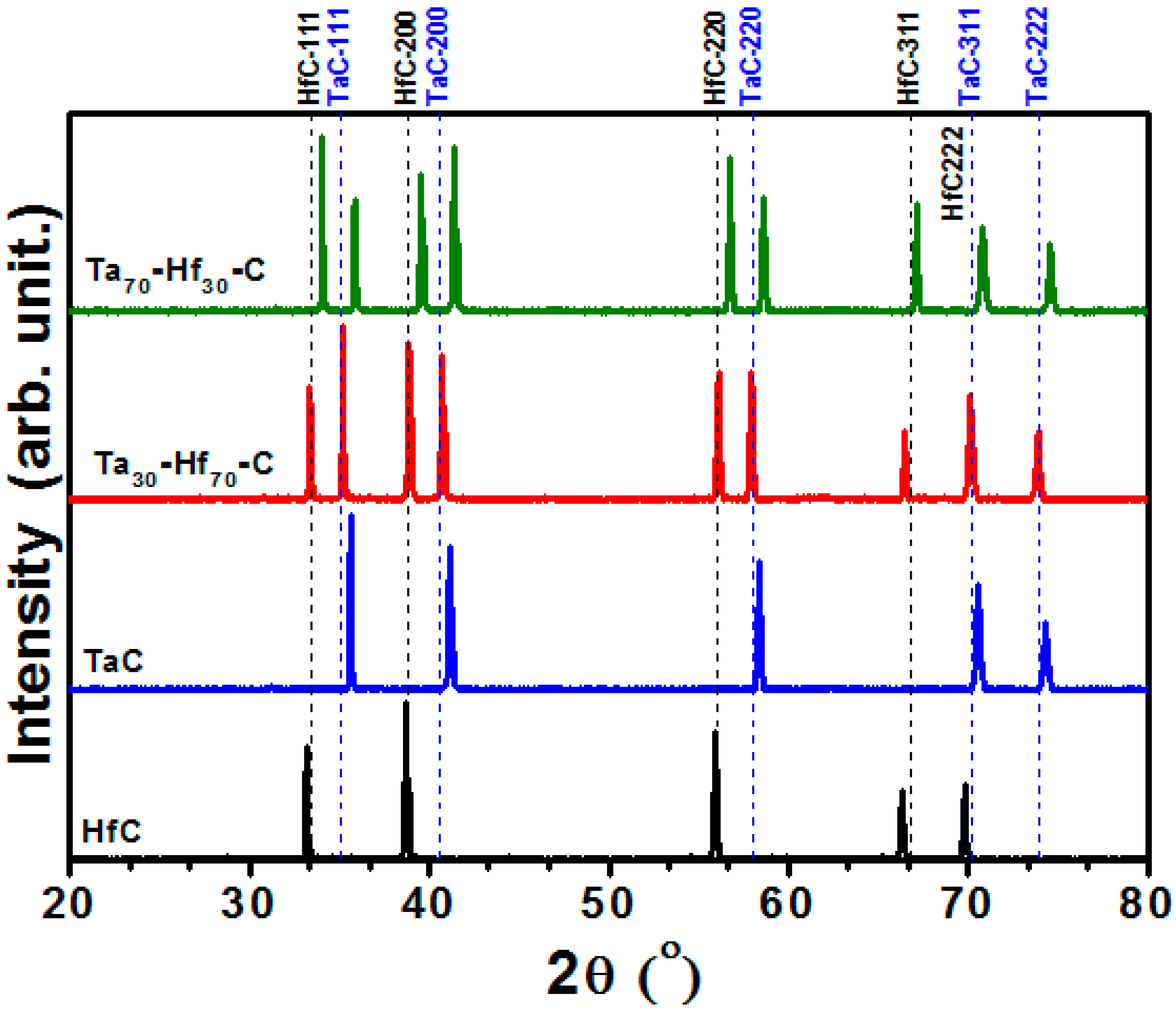
3.1. Structural Analysis by X-ray Diffraction

Figure 2 shows the diffraction patterns corresponding with the TaC and HfC individual coatings and the system conformed by (Ta30-Hf70-C) and (Ta70-Hf30-C) respectively, deposited on a silicon substrate. The results evidenced that the HfC individual coating presented high intensity Bragg peaks located under the angles 2 θ = 33.408°, 38.784°, 56.029°, 66.763°, 70.178°, 83.219° and 98.653°, corresponding with planes (111), (200), (220), (311), (222), (400) and (331), respectively. These corresponded with a single cubic crystal structure (CS) and the space group Fm3m (225), which was indexed under the indexing file JCPDF 00-006-0510. On the other hand, the TaC individual coatings evidenced Bragg peaks located at angles 2 θ = 35.023°, 40.606°, 58.765°, 70.178° and 73.997°, corresponding with crystallographic planes (111), (200), (220), (311) and (222), respectively. These corresponded with a single cubic crystal (CS) and the space group Fm3m (225), which was indexed with indexing file JCPDF 00-002-1023. The Ta30-Hf70-C and Ta70-Hf30-C coatings, which do not have international files, were analyzed using the files of the individual coatings, where the presence of the same Bragg peaks attributed to the conformation of both materials (HfC and TaC) was evidenced. The TaX-HfX-1C material was formed by a complex conjugate product of an adjustment from the TaC and HfC cubic phase, taking into account that the crystalline solution of this ternary carbide is formed at temperatures higher than 2500 °C. In this sense, the diffraction patterns for TaX-HfX-1C as a function of the Ta and Hf concentrations showed the presence of intensity maxima in the diffraction patterns of TaX-HfX-1C and were modified according to the Ta/Hf concentration ratio. Moreover, this displacement of the peaks was identified according to the stoichiometric relationship with each specific structure. These displacements of the Bragg peaks were attributed to the distortion of the crystal lattice due to the inclusion of Hf and Ta atoms, which modify the lattice parameters caused by residual stresses within the crystal structure [4,7,8].

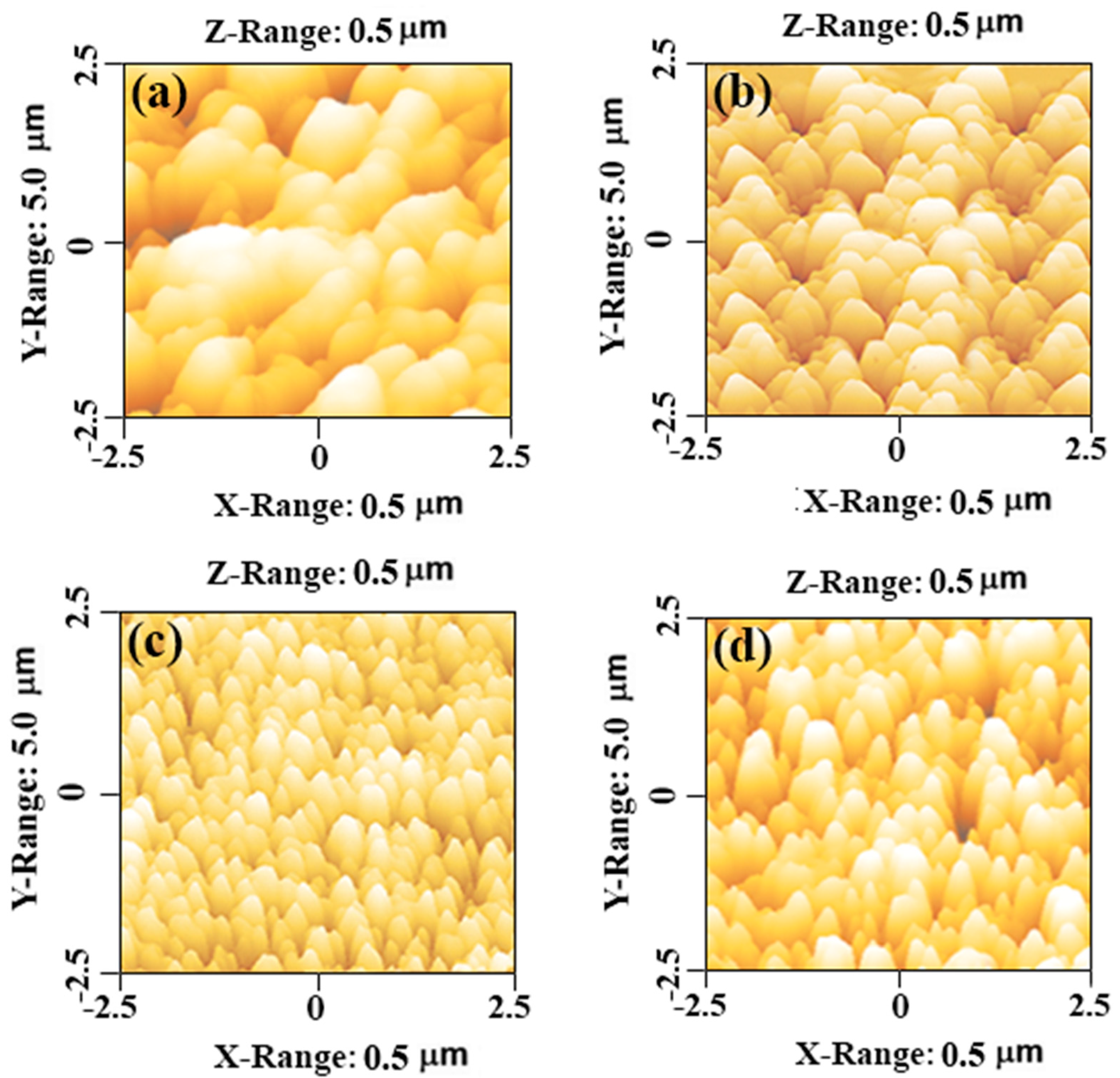
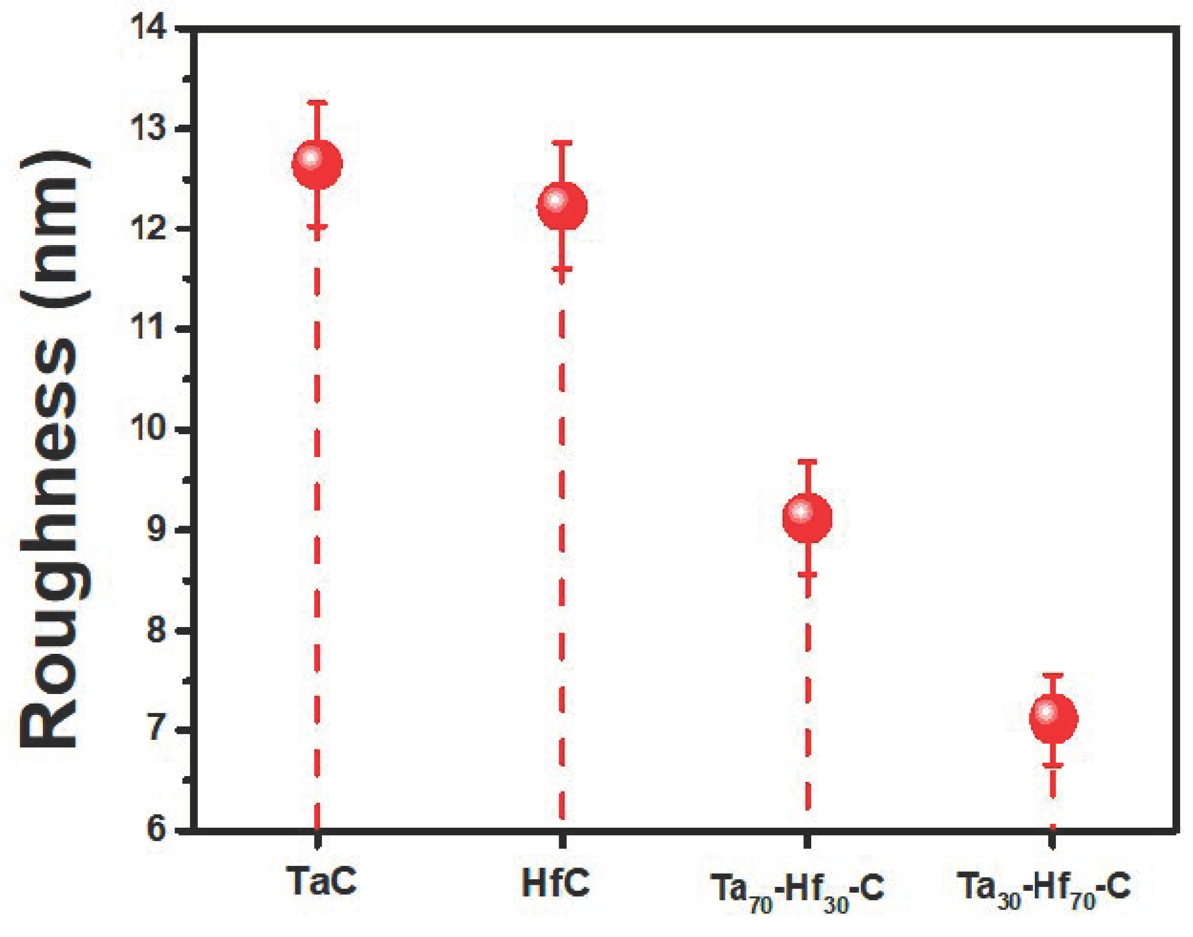
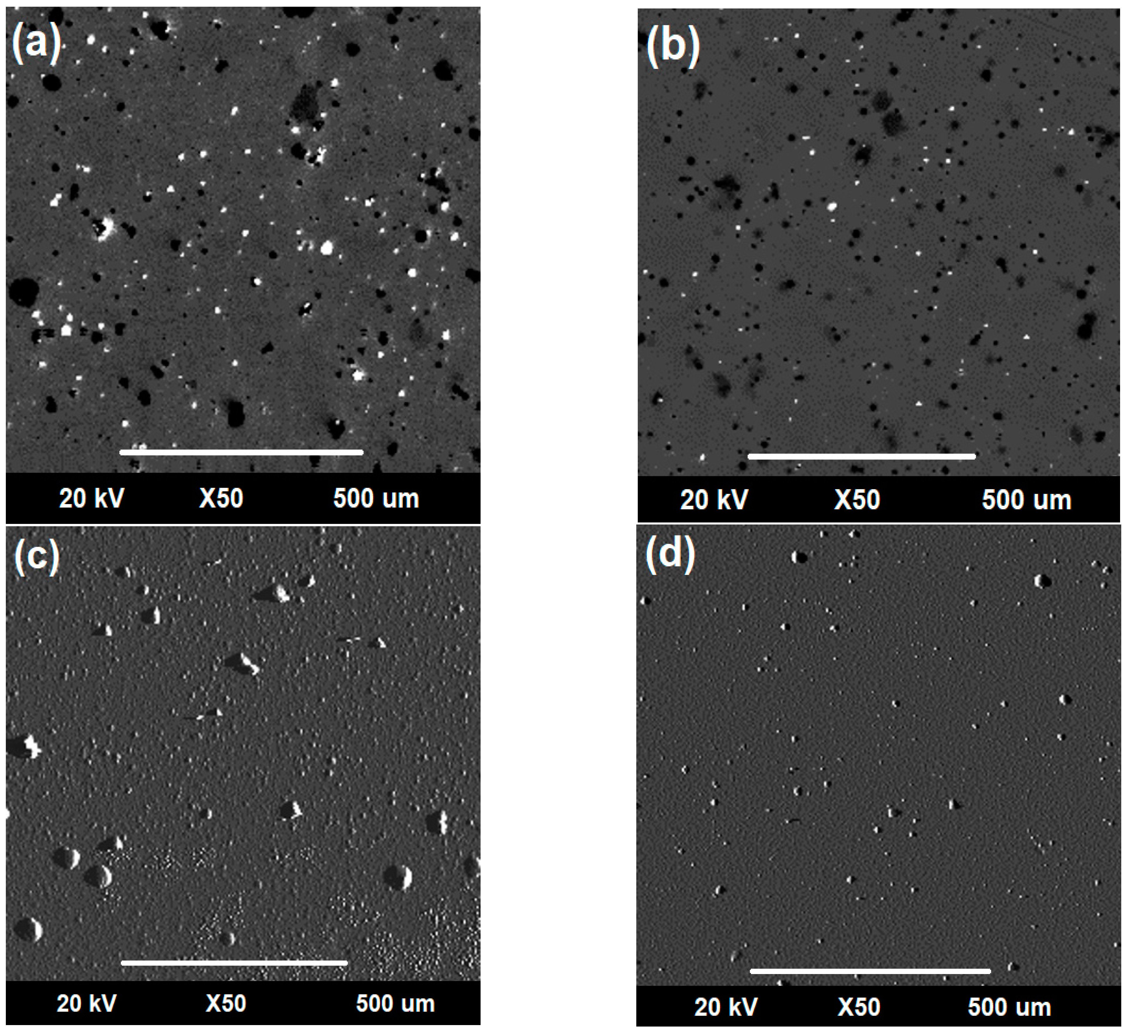
3.2. Morphological Analysis

The surface characteristics of the TaC and HfC individual coatings and the (Ta30-Hf70-C) and (Ta70-Hf30-C) coatings deposited on a silicon substrate were analyzed by AFM. Figure 3 shows the images obtained from the surfaces of the coatings, which showed that the whole system presented a circular morphology and was free of porosities and/or surface defects. Figure 3c,d, which corresponds with the (Ta30-Hf70-C) and (Ta70-Hf30-C) composites, presents the difference compared with the individual coatings (Figure 3a,b). Much smaller and columnar grains were obtained, especially for the (Ta30-Hf70-C) composite. This surface behavior was attributed to two main factors: the ratio of the TaC and HfC individual compounds within the structures where the HfC individual coating (Figure 3b) presented a smaller grain size with more circular grains in which a higher Hf content caused a more regular and homogeneous surface; and to surface factors attributed to residual stresses due to the distortion of the crystal lattice, as corroborated in Figure 3c for the (Ta30-Hf70-C) composite [7,8].
Figure 4 presents the quantitative values of the roughness for the TaC and HfC individual coatings and the Ta70-Hf30-C and Ta30-Hf70-C coatings. The results showed that the TaC individual coating presented a higher roughness of all the coatings in this study, with a roughness of approximately 12.65 nm. The HfC coating presented a roughness of approximately of 12.23 nm, indicating a decrease of 3.32% with respect to the TaC. On the other hand, the Ta70-Hf30-C and Ta30-Hf70-C coatings presented roughness values of approximately 9.12 nm and 7.11 nm, respectively. The results obtained showed that the composite coatings presented a lower roughness than the individual coatings due to fact that the inclusion of Ta and Hf atoms within the same crystalline structure caused a distortion of the lattice, generating a denser and more compact structure compared with the individual coatings. In addition, these structural factors modified the columnar growth of the coatings during the deposition and nucleation process of the coatings. For the composite based on Ta30-Hf70-C, lower surface roughness values were obtained compared with the other composite and individual coatings; these characteristics would influence the corrosive properties of the coatings obtained [9,10,11].

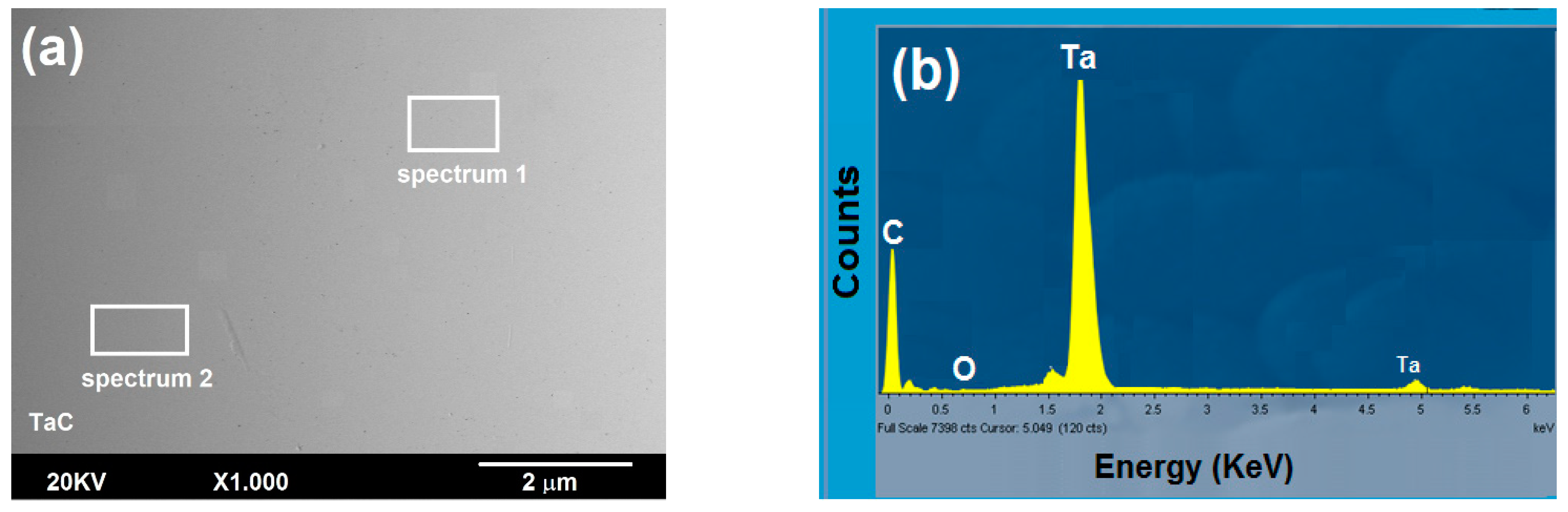
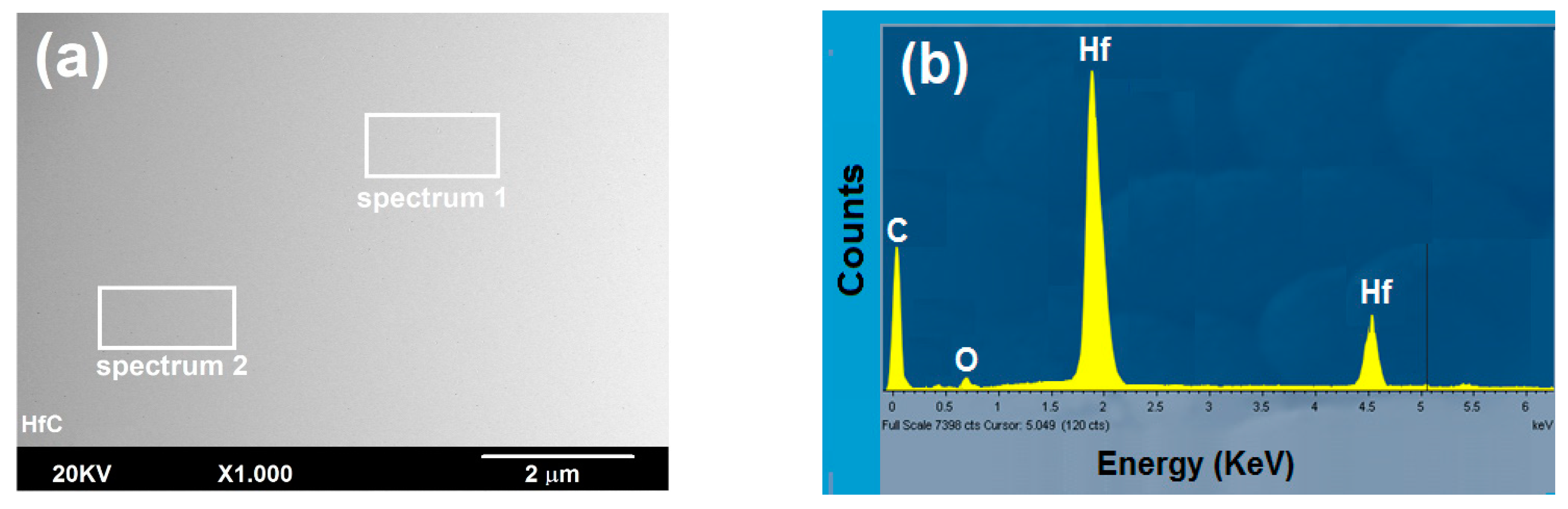
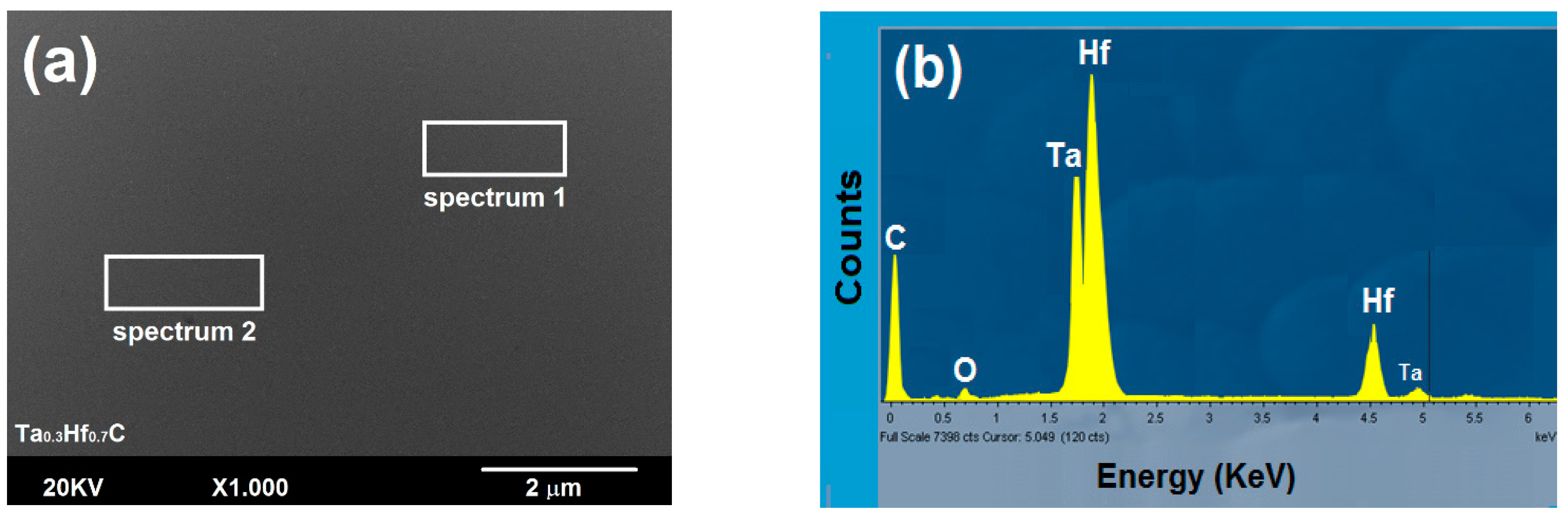
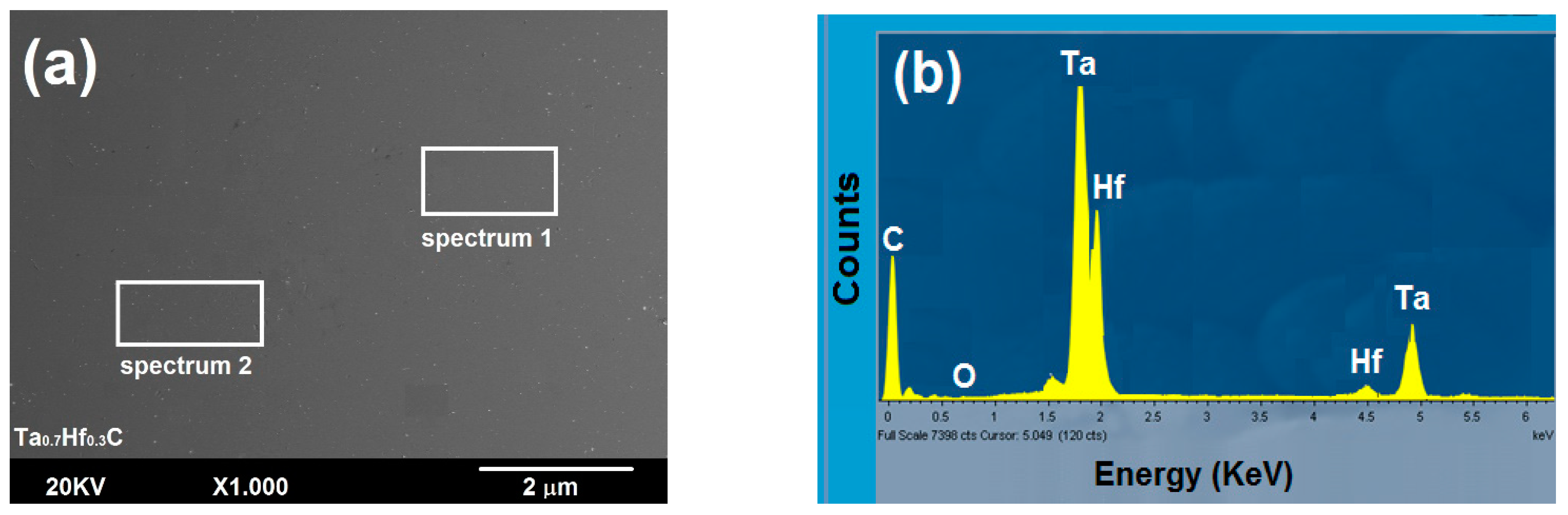
3.2.1. Surface Study by SEM-EDS

Figure 5a, Figure 6a, Figure 7a and Figure 8a show the surface SEM micrographs obtained for all coatings. From these micrographs, the area where the compositional analysis spectra were taken for the surfaces could be evidenced (Figure 5b, Figure 6b, Figure 7b and Figure 8b). These figures present the spectra of each surface, where the presence of the main elements used during the deposition process were verified. Finally, by means of an EDS elemental analysis, the stoichiometric relationship for the coatings was verified, mainly for the Ta70-Hf30-C and Ta30-Hf70-C coatings.

3.2.2. Cross-Section Analysis SEM

Figure 9 shows the micrograph of the cross-section of the coatings obtained; the thickness measurements are presented, corroborating that the coatings presented thicknesses of approximately 600 nm. From these SEM micrographs, it was possible to show that the coating composed of Ta30-Hf70-C presented a denser and more compact coating compared with the others. This type of growth was attributed to structural factors due to the incorporation of Hf and Ta atoms within the same simple cubic structure. This corroborated the results obtained previously, where it was evidenced that the Ta30-Hf70-C coating presented a lower surface roughness as it was a denser and more compact coating compared with the others.

3.3. Corrosion Study

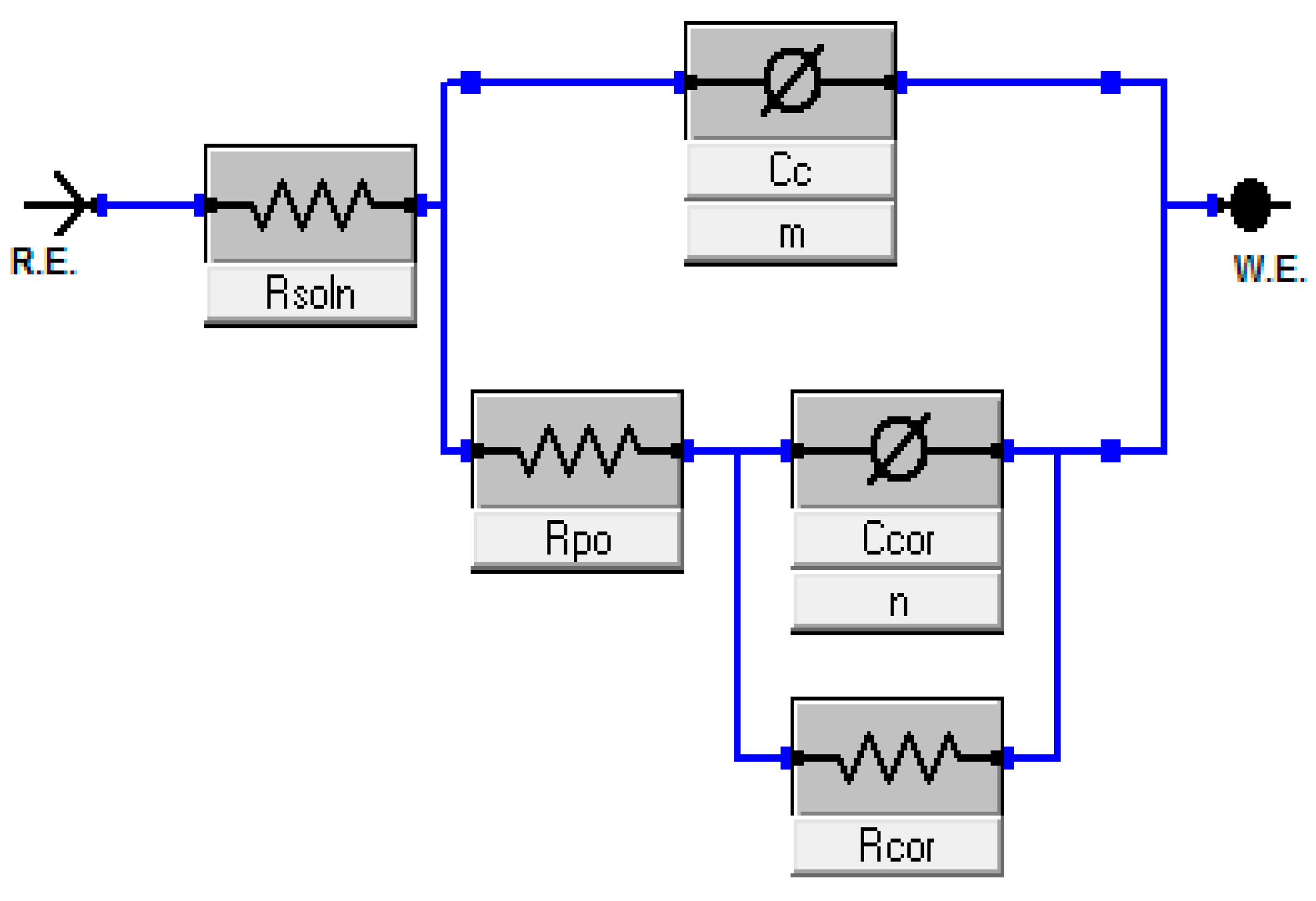
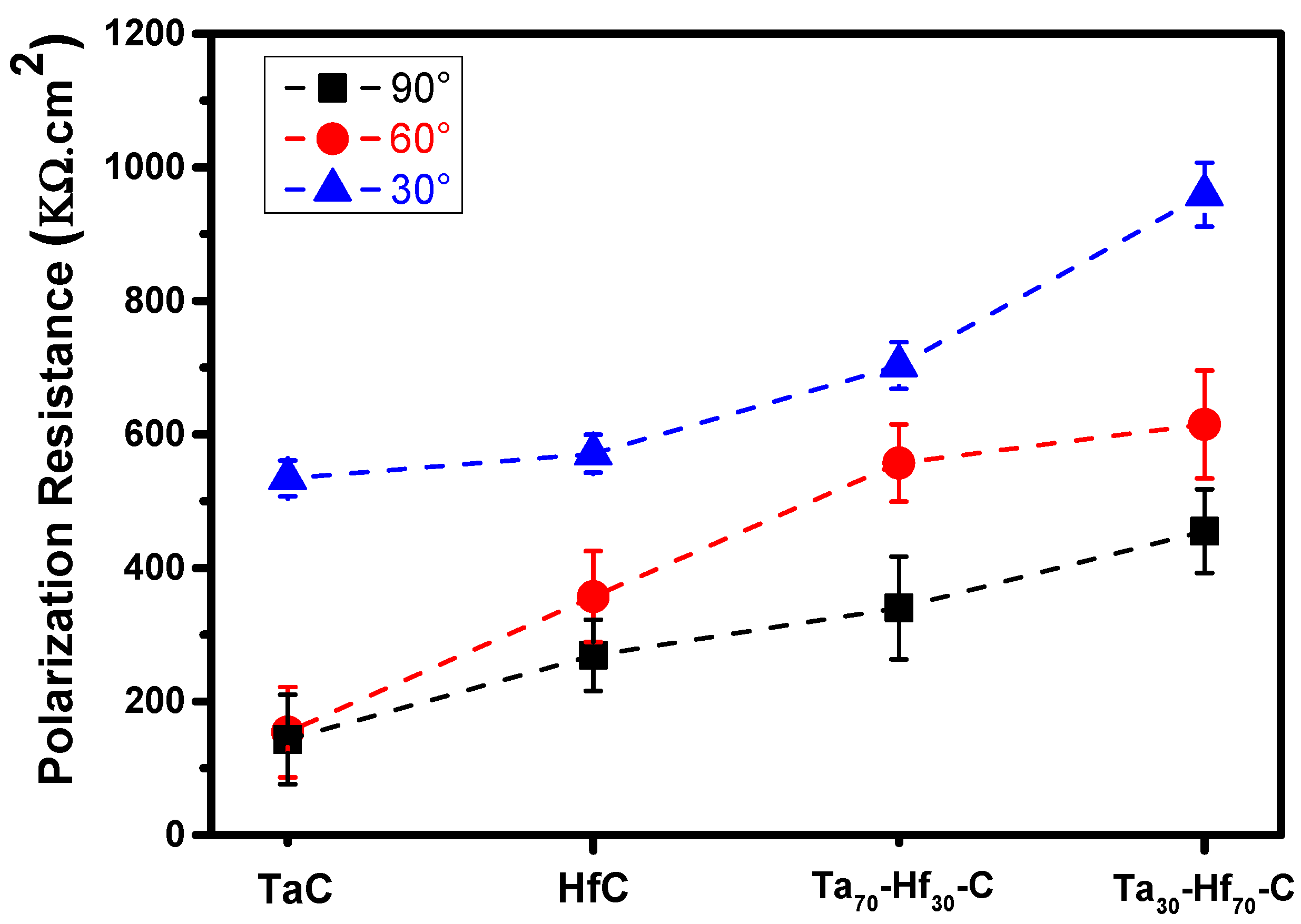
3.3.1. Electrochemical Impedance Spectroscopy (EIS)

The analysis of the corro-erosive behavior of the TaC and HfC individual coatings and the (Ta70-Hf30-C) and (Ta30-Hf70-C) coatings deposited on AISI 316 LVM stainless steel substrates was performed by means of the electrochemical impedance spectroscopy (EIS) technique as a function of the impact angle of the abrasive particles (30°, 60° and 90°), with the purpose of evaluating the influence of the impact angle on the structural integrity of the coatings. For the corro-erosive study, the use of an equivalent circuit (a Randles cell) was implemented (Figure 10), which allowed the adjustment of the experimental data during the whole electrochemical test. In this proposed equivalent circuit, the capacitance was configured in parallel with the impedance of the coating due to the ionic transfer reaction generated during the whole corro-erosive test. Moreover, for the coatings obtained by physical vapor deposition (PVD) processes, the equivalent circuit was composed of ideal capacitors [12]. Based on the surface roughness data obtained by means of the atomic force microscopy (AFM) technique, it was determined that the roughness of all the coatings was on the nanometer scale, especially the (Ta70-Hf30-C) and (Ta30-Hf70-C) coatings, which presented a higher surface homogeneity, higher density and a significant decrease in surface defects compared with the TaC and HfC individual coatings. This behavior generated a significant decrease in the frequency dispersion of the system under the corro-erosive test. On the other hand, for the equivalent circuit presented in Figure 10, a fit with the impedance data for the coating/solution system—which contained two distributed constant phases elements, Cc and Ccor—was used to account for the two relaxation time constants. When the system was subjected to high frequencies, the Ccorr and Rcorr components played a determining role as these elements simulated the electrochemical behavior of the surface passivating film, thus allowing the analysis of the dielectric properties present at the interface of the solution and the coating. On the contrary, at very low frequencies as in our case, there was a highly predominant behavior of the Cc and Rp components, which allowed us to identify the electrochemical behavior between the coatings and the substrate. The admittance representation of the CPE ( Y CPE ) showed a fractional power dependent on the angular frequency “ω” (Equation (1)) [6,13].
Figure 11 shows the Nyquist diagram corresponding with the TaC and HfC individual coatings and the (Ta70-Hf30-C) and (Ta30-Hf70-C) coatings, respectively, as a function of the incidence angle of the abrasive particles on the surfaces under study (30°, 60° and 90°). These diagrams allowed us to determine the relationship between the arc of the semicircle and the imaginary impedance (Z′′) vs. the real impedance (Z′). From these results, it was possible to show that at each angle of incidence (30°, 60° and 90°), a wider semicircle was obtained for the (Ta70-Hf30-C) and (Ta30-Hf70-C) composites compared with the other coatings. This behavior exhibited by the (Ta30-Hf70-C) composite was attributed to physical and surface factors because this coating presented a much denser and more compact structure than the individual coatings associated with a higher distortion of the crystalline lattice. In addition, this composite presented a lower roughness and a smaller grain size, as shown in Figure 3 and Figure 4, respectively. These characteristics (structural and superficial), generated a denser coating with a lower porosity, which decreased the diffusion of the Cl- ions present in the electrolyte towards the substrate. Therefore, the coating composed of (Ta30-Hf70-C) presented a higher impedance in comparison with the coating composed of (Ta70-Hf30-C) and especially the TaC and HfC individual coatings [6,7,14].
Finally, Figure 11 allows a direct comparison of the function of the impedance generated on the surface of the coatings. It was possible to establish that by increasing the impact angles, the amplitude of the semicircle decreased, maintaining the same trend. This decrease in the amplitude of the semicircles was due to the structural damage of the coatings generated by the impact of the abrasive particles on the surface. Therefore, the 90° angles caused a higher structural failure of the coatings because, for coatings of a ceramic nature, this angle in particular was a critical angle, generating a rapid failure of the coatings by the exchange of the kinetic energy of the abrasive particles and leaving the metallic substrate partially exposed during the corro-erosive test, thus decreasing the impedance of the system [6,7,14,15,16,17].
In order to analyze the polarization resistance of the coatings obtained, the results presented in the Nyquist diagram and the equivalent circuit (Figure 10 and Figure 11) were used. By means of Equations (1) and (2), it was possible to establish that for very low frequencies (ω = 0), as in our study, and taking into account that Rs << Rp, the value of the polarization resistance (Rp) of the coatings obtained was approximately equal to Z c a l ω i , where ω = 0 was the radial frequency, Rs was the electrolyte resistance, Rpo was the polarization resistance and C was the double-layer capacitance [7,9].
Y CPE = Y p · j ω α
Z c a l ω i = R s o l n + R p o 1 + R p o Y P c j ω i α + R c o r 1 + R c o r Y c o r j ω i γ
where Yp is a real constant; −1 < α < 1; when α = 0, CPE is a resistor; when α = 1, it is a capacitor; and when α = −1, it is an inductor. Finally, if α = 0.5, CPE is the Warburg admittance. We calculated the impedance Z c a l ω i of the equivalent circuit of Figure 5 for a specific angular frequency value ( ω i ).
Figure 12 shows the polarization resistance (Rp) values for the TaC and HfC individual coatings and the (Ta70-Hf30-C) and (Ta30-Hf70-C) coatings as a function of the impact angle of the abrasive particles on the surface. The results showed that the coating composed by (Ta30-Hf70-C) presented a higher resistance to polarization for all angles of incidence of the abrasive particles. These characteristics (a higher Rp) were attributed to physical and surface factors; having a more homogeneous surface with a lower roughness, the external kinetic energy associated with the impact of the abrasive particles on the surface was distributed to a larger contact area compared with the other coatings, which presented a higher surface roughness (Figure 4). Another important factor was related to structural factors such as the residual stresses during the deposition process, which modified the periodic potential of the crystalline structure and caused a higher resistance to the corrosive environments. In addition, the distortion generated in the crystalline structure caused a denser and more compact structure with a smaller grain size, which was able to withstand the kinetic energy associated with the impact of the abrasive particles [6,7,15].

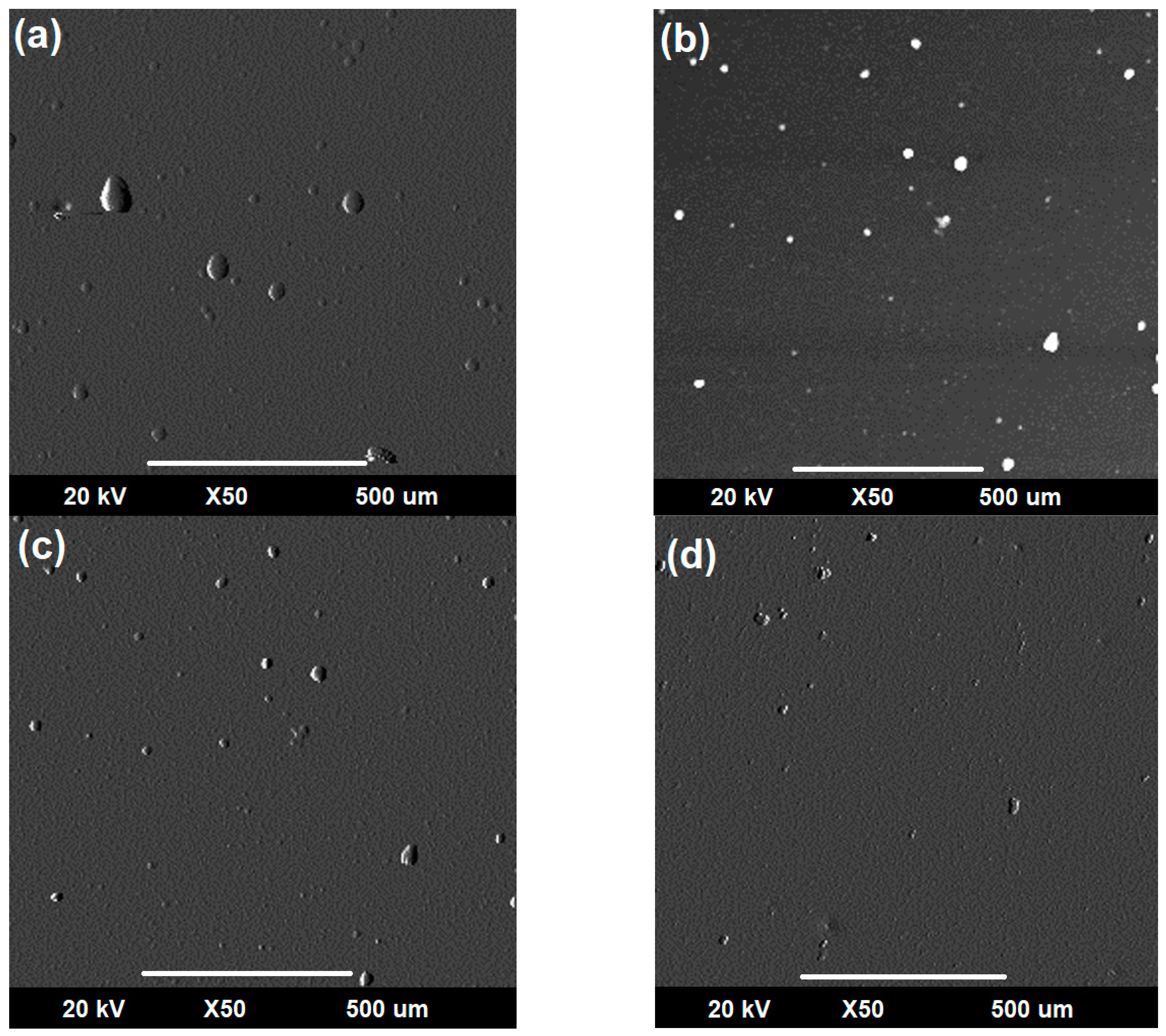
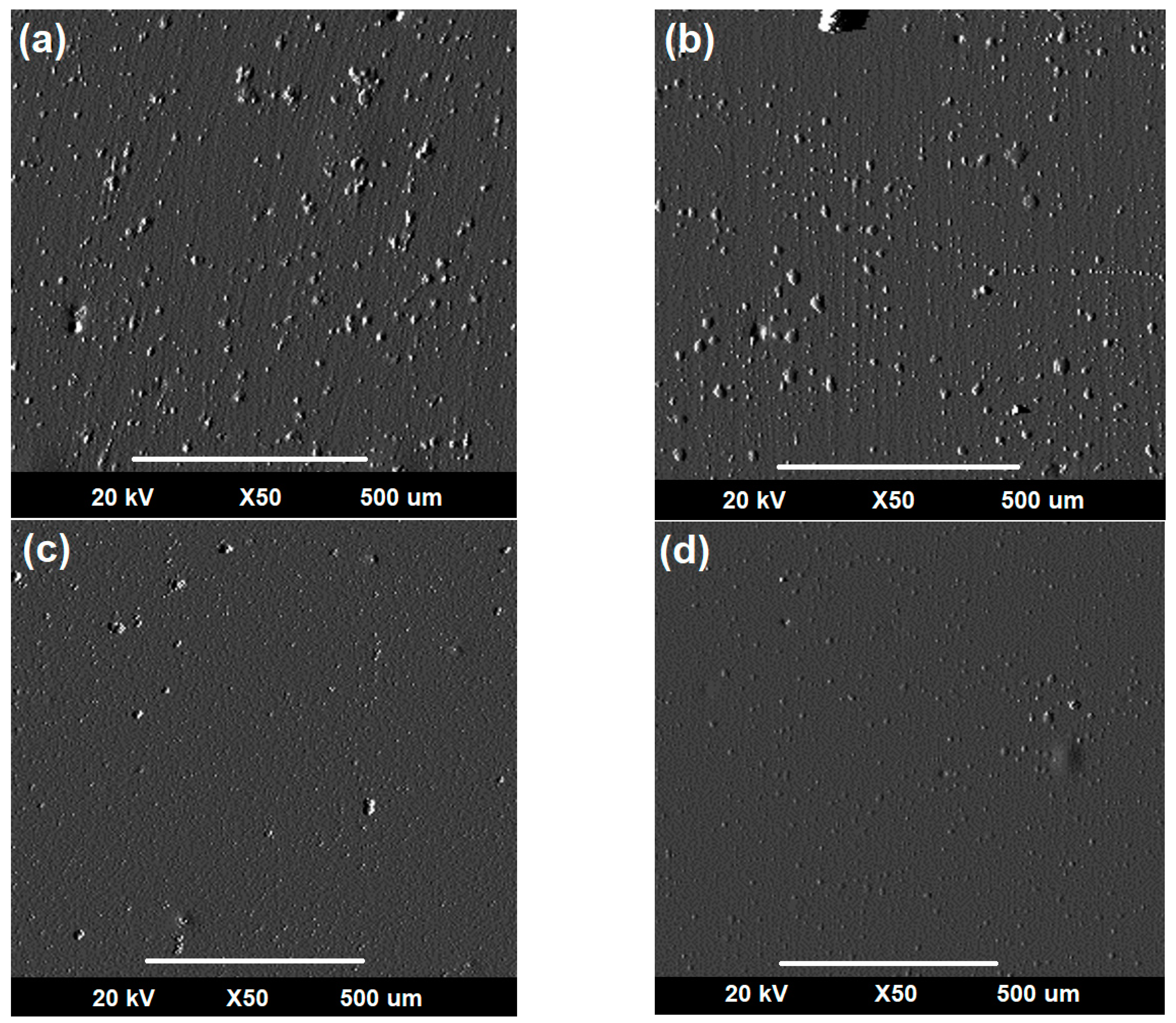
3.3.2. Evaluation of Corro-Erosive Damage by SEM as a Function of the Impact Angle

Figure 13 presents the SEM micrographs corresponding with the surface of the TaC and HfC individual coatings and the (Ta70-Hf30-C) and (Ta30-Hf70-C) coatings after the corro-erosive test with an impact angle of 30° of the abrasive particles. From these micrographs, it was possible to evidence damage generated in the structural integrity of the coating (corrosive pitting), leaving the metallic substrate partially exposed and increasing the corrosion rate due to the impact of the abrasive particles during the corro-erosive study. Figure 13a,b shows the surface of the TaC and HfC individual coatings, which presented higher structural damage compared with the (Ta70-Hf30-C) and (Ta30-Hf70-C) coatings (Figure 13c,d). From these micrographs, it was possible to establish that the (Ta30-Hf70-C) coating presented lower structural damage due to the structural and surface properties evidenced by this coating in the previous test, which generated a higher polarization resistance compared with the others. Figure 14 and Figure 15 show the SEM micrographs of the surfaces of the coatings after the corro-erosive test with an impact angle of the abrasive particles of 60° and 90°, respectively. By means of these results, it was possible to evidence the structural damage generated by the impact of the abrasive particles on all coatings. Finally, this superficial study was able to demonstrate the incidence of the impact angle of the particles, where it was ascertained that when using high angles (90°), higher structural damage (corrosive pitting) was generated on the coatings as these right angles on the surfaces of the material produced a higher wear on the structural integrity of the coatings. In addition, it was possible to show that the same trend as the previous results was presented (Figure 8), where the composite formed by (Ta30-Hf70-C) presented lower structural wear; thus, this composite is the best alternative to be implemented as a protective coating on engineering devices in corro-erosive applications [4,7].

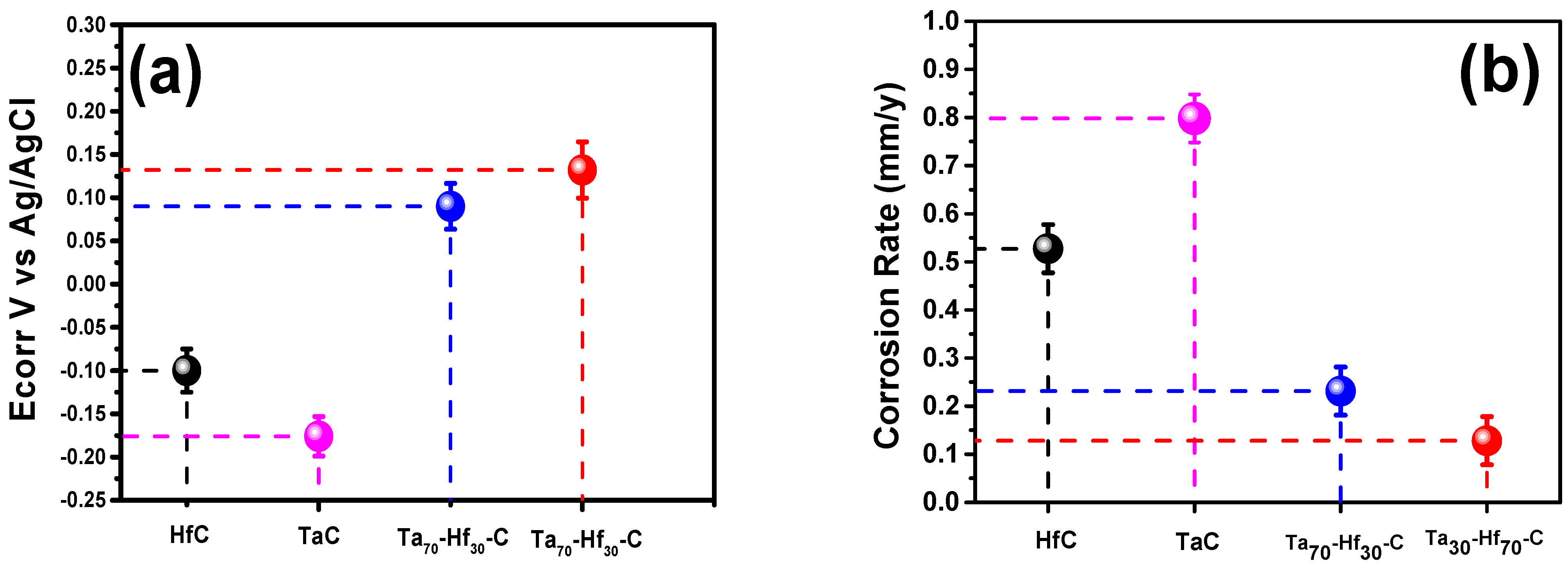
3.3.3. Tafel Polarization Curves
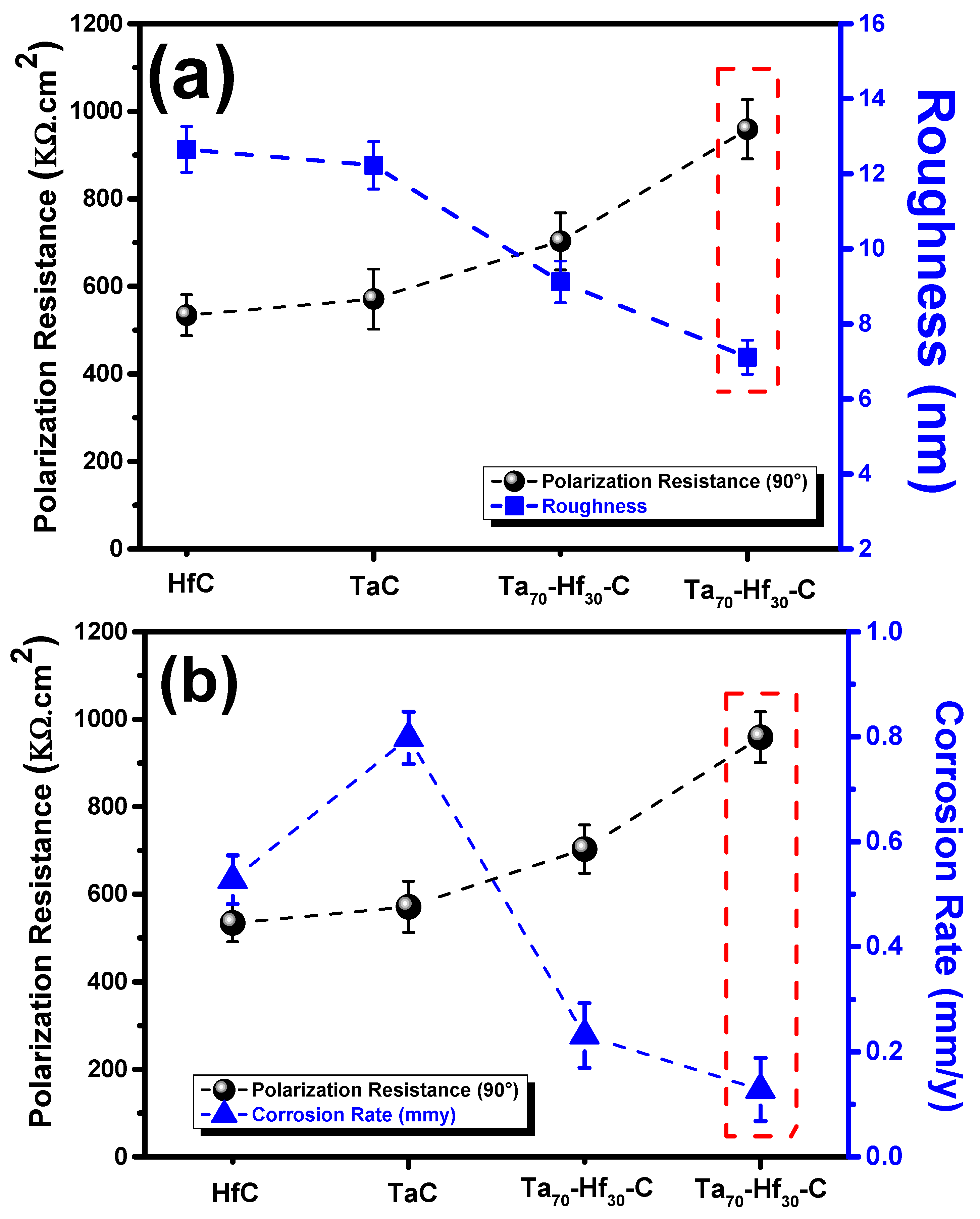
The Tafel polarization curves for all coatings are presented in Figure 16. These curves allowed us to show the values associated with the anodic and cathodic slopes and to determine different properties such as the corrosion rate of the coatings obtained, which was a crucial factor in this research. From Figure 16, it was possible to show that the Tafel curves for the (Ta70-Hf30-C) and (Ta30-Hf70-C) composite coatings presented a shift to the right (higher potentials) compared with the TaC and HfC individual coatings. This electrochemical behavior was attributed to the fact that these coatings presented denser and more compact structures with a much more regular surface, which decreased the diffusion of the corrosive ions present in the electrolyte towards the metal substrate. Finally, it was also determined that the (Ta30-Hf70-C) coating presented the same tendency as in the surface properties. This was due to the fact that this coating, by presenting a more homogeneous surface (fewer surface irregularities), decreased the possible inclusion zones of the electrolyte in the surface irregularities of the coating. Therefore, this coating presented a higher resistance against corrosive environments compared with the (Ta70-Hf30-C) composite, protecting the metallic substrate [13,18].
Subsequently, by means of the results obtained from the Tafel polarization curves and the EIS results, it was possible to calculate other important characteristics for the comparative study of the coatings such as the corrosion potential and corrosion rate calculated by Equations (3) and (4); these are presented in Table 3. These results showed that the TaC and HfC individual coatings presented low properties in comparison with the composite coatings as they presented a low corrosion potential and a high corrosion rate, indicating that these individual coatings were highly susceptible to aggressive environments. On the other hand, the (Ta70-Hf30-C) and (Ta30-Hf70-C) coatings presented better properties compared with the individual coatings; the comparison between these coatings evidenced that the (Ta30-Hf70-C) coating presented the best electrochemical properties (a higher potential and lower corrosion rate), which corroborated the results obtained for the corro-erosive properties [6,7,13,19].
I c o r r = β a   β c 2.303 R p β a + β c  
R a t e   C o r r o s i o n = I c o r r · K · E w d .
Figure 17a,b shows the corrosion potential and corrosion rate, respectively, for all coatings, as analyzed above. The individual coatings continued to present lower properties against corrosive and corro-erosive environments. Figure 17a shows the corrosion potential obtained for the coatings, where potentials of −0.1 V and −0.176 V were indicated for the TaC and HfC individual coatings, respectively, and potentials of 0.09 and 0.132 V were indicated for the (Ta70-Hf30-C) and (Ta30-Hf70-C) coatings, respectively. These results corroborated that the individual coatings were susceptible to low potentials. In addition, it was possible to determine that the (Ta30-Hf70-C) coating presented an increase of approximately 47% in the corrosion potential, indicating that this coating presented a higher resistance to the diffusion of Cl− atoms through the coating, generating a higher resistance to corrosive environments [6,19]. Figure 17b shows the corrosion rate values for all the coatings, and it was corroborated that the individual coatings continued to present the same trend as the (Ta30-Hf70-C) coating continued to present a lower corrosion rate, attributed to the physical and surface factors mentioned above.
According to Cui and Zhao [20,21], a passive film initially grows by the oxidation of all components in the steel, with the film thickening rate being controlled by ion migration under a high electronic field. This is followed by the dissolution of the film as the electric field across the growing film relaxes to a given value, resulting in the leaching of Ta and Hf components into a solution. In the present work, the removal of dissolved oxygen had no detectable effect on the film dissolution whereas the acidification of the solution increased the quasi-emission, which was indicative that dissolution was promoted. In this sense, the effect of the solution chemistry on the diffusivity of the point defect inside the passive film was associated with the diffusion coefficient (DO) of the point defect (oxygen vacancies and/or interstitial cations), which is a fundamental parameter to describe the transport of the point defects and the specific properties of the coating. Two widely accepted approaches are used to calculate the diffusivity of a point defect. In addition, the passive current density can also reflect the density, and diffusion is a point defect through the passive coating relative to the quasi-emission of an n-type semiconductor coating [21]. In relation to the above results, the Ta30-Hf70-C and Ta70-Hf30-C coatings belonged to less extreme environments and were less susceptible to the corrosion effect than the binary coatings TaC and HfC. Therefore, the passive film properties—which are influenced by the removal of dissolved oxygen and acidification of the coatings, especially Ta30-Hf70-C materials—were the critical factors for corrosion in these environments. The variation in a few passivation parameters and the characteristics are listed in Figure 18.

3.4. Merit Index

The surface and corro-erosive studies of the coatings were obtained; Figure 19 shows a direct correlation between the surface and the corrosion properties in order to determine which coating presented the best set of properties. Figure 19a shows a direct correlation between the polarization resistance (Rp) obtained with an angle of incidence of 90° and the roughness for the coatings, where it was possible to establish that the (Ta30-Hf70-C) coating presented the best properties and that these properties were directly related, as a more regular surface generates a higher protection against corro-erosive environments. Figure 19b shows the merit index relating to the polarization resistance (Rp) obtained at an incidence angle of 90° and the corrosion rate for the coatings, where it was determined that the (Ta30-Hf70-C) coating presented the best set of properties.

4. Conclusions

The structural study of the coatings showed that the TaC and HfC individual coatings presented a simple cubic structure (CS) and that the Ta-Hf-C composites maintained the same crystalline structure.
A surface analysis by AFM determined that the TaC and HfC individual coatings presented roughnesses of approximately 12.65 nm and 12.23 nm, respectively. The (Ta70-Hf30-C) and (Ta30-Hf70-C) coatings presented an approximate roughness of 9.12 nm and 7.11 nm, respectively.
The evaluation of the polarization resistance (Rp) as a function of the impact angle of the abrasive particles determined that, for all the coatings, higher structural damage occurred at an angle of 90° and that the (Ta30-Hf70-C) coating had the higher polarization resistance at all impact angles.
The merit index concluded that the (Ta30-Hf70-C) coating obtained the best set of surface and corro-erosive properties; thus, this system is the best option to be implemented as a protective coating against aggressive environments.

Author Contributions

Conceptualization, C.H.O. and J.C.C.; methodology, S.S.S., W.A., J.S.-M. and J.B.R.; supervision, C.H.O. and J.C.C., C.H.O., S.S.S., J.C.C., W.A., J.S.-M. and J.B.R. All authors have read and agreed to the published version of the manuscript.

Funding

This research received no external funding.

Institutional Review Board Statement

Not applicable.

Informed Consent Statement

Not applicable.

Data Availability Statement

Not applicable.

Acknowledgments

This research was supported by the Tribology, Polymers, Powder Metallurgy and Solid Waste Transformation (TPMR) research group of the Universidad del Valle; And the “Universidad Militar Nueva Granada” through the INV_ING 3123 project.

Conflicts of Interest

The authors declare no conflict of interest.

References

  1. Wood, R. Erosion–corrosion interactions and their effect on marine and offshore materials. Wear 2006, 261, 1012–1023. [Google Scholar] [CrossRef]
  2. Okada, T.; Awazu, K.; Kawasaki, H. Influence of cavitation erosion on corrosion fatigue and the effect of surface coatings on resistance. Wear 1980, 63, 51–70. [Google Scholar] [CrossRef]
  3. Ou, X.-M.; Sun, Z.; Sun, M.; Zou, D.-L. Hot-corrosion mechanism of Ni-Cr coatings at 650 °C under different simulated corrosion conditions. J. China Univ. Min. Technol. 2008, 18, 444–448. [Google Scholar] [CrossRef]
  4. Feng, G.; Li, H.; Yao, X.; Zhou, H.; Yu, Y.; Lu, J. Ablation resistance of HfC-TaC/HfC-SiC alternate coating for SiC-coated carbon/carbon composites under cyclic ablation. J. Eur. Ceram. Soc. 2021, 41, 3207–3218. [Google Scholar] [CrossRef]
  5. Nyberg, H.; Tokoroyama, T.; Wiklund, U.; Jacobson, S. Design of low-friction PVD coating systems with enhanced running-in performance—carbon overcoats on TaC/aC coatings. Surf. Coat. Technol. 2013, 222, 48–54. [Google Scholar] [CrossRef]
  6. Guzmán, P.; Aperador, W.; Yate, L. Enhancement of the Pitting Corrosion Resistance of AISI 316LVM Steel with Ta-Hf-C/Au Bilayers for Biomedical Applications. J. Nanomater. 2017, 2017, 6825250. [Google Scholar] [CrossRef]
  7. Zhang, J.; Zhang, Y.; Zhu, X.; Fu, Y.; Chen, R.; Gai, W. Design and preparation of multilayer TaC/HfC coating: Ablation behavior under oxyacetylene flame with different heat flux. Corros. Sci. 2022, 204, 110385. [Google Scholar] [CrossRef]
  8. Zhao, Y.; Xu, J.; Peng, S. Synthesis and evaluation of TaC nanocrystalline coating with excellent wear resistance, corrosion resistance, and biocompatibility. Ceram. Int. 2021, 47, 20032–20044. [Google Scholar] [CrossRef]
  9. Ortiz, C.; Aperador, W.; Caicedo, J. Physical properties evolution of β-tricalcium phosphate/hydroxyapatite heterostructures in relation to the bilayer number. Thin Solid Film. 2022, 752, 139256. [Google Scholar] [CrossRef]
  10. Zhang, J.; Zhang, Y.; Chen, R.; Zhu, X.; Fu, Y. Effect of microstructure on the ablation behavior and mechanical properties of CVD-HfC coating. Corros. Sci. 2021, 192, 109815. [Google Scholar] [CrossRef]
  11. Hernandez-Rengifo, E.H.-R.; Ortiz, C.; Hidalgo, C.; Ballesteros, J.; Caicedo, J. Comparative Study of Tribological and Mechanical Properties Between Single Layers of Al2O3 and Si3N4 Deposited on AISI 316 Stainless Steel. Tribol. Ind. 2021, 43, 259–273. [Google Scholar] [CrossRef]
  12. Chaparro, W.A.; López, E.V.; Uscategui, A.V. Electrochemical corrosion resistance study of electroplated nickel/copper coatings obtained by pulsed current. Ing. Y Desarro. 2010, 27, 14. [Google Scholar]
  13. Ortiz, C.H.; Caicedo, J.C.; Aperador, W. Corrosion Properties of Heterostructured [8YSZ/Al2O3] N Coatings as a Function of the Bilayer Number. J. Mater. Eng. Perform. 2021, 31, 1679–1692. [Google Scholar] [CrossRef]
  14. Tan, K.; Wharton, J.; Wood, R. Solid particle erosion–corrosion behaviour of a novel HVOF nickel aluminium bronze coating for marine applications—correlation between mass loss and electrochemical measurements. Wear 2005, 258, 629–640. [Google Scholar] [CrossRef]
  15. Ortiz, C.H.; Aperador, W.; Caicedo, J.C. Electrochemical Study of Anodized AZ31 Magnesium Alloy (Mg/MgO) Immersed under Watered Cementice Paste. J. Mater. Eng. Perform. 2022, 1, 1–10. [Google Scholar] [CrossRef]
  16. Caicedo, J.; Cabrera, G.; Caicedo, H.; Amaya, C.; Aperador, W. Nature in corrosion–erosion surface for [TiN/TiAlN] n nanometric multilayers growth on AISI 1045 steel. Thin Solid Film. 2012, 520, 4350–4361. [Google Scholar] [CrossRef]
  17. Ortiz, C.; Aperador, W.; Caicedo, J. Electrochemical response of (β-TCP and HA) individual coatings and [β-TCP/HA] multilayers coatings exposed to biocompatible environments. Surf. Coat. Technol. 2022, 435, 128266. [Google Scholar] [CrossRef]
  18. Cheng, Y.-L.; Qin, T.-W.; Wang, H.-M.; Zhang, Z. Comparison of corrosion behaviors of AZ31, AZ91, AM60 and ZK60 magnesium alloys. Trans. Nonferrous Met. Soc. China 2009, 19, 517–524. [Google Scholar] [CrossRef]
  19. Morks, M.F.; Cole, I.; Corrigan, P.; Kobayashi, A. Electrochemical Characterization of Plasma Sprayed Alumina Coatings. J. Surf. Eng. Mater. Adv. Technol. 2011, 1, 107–111. [Google Scholar] [CrossRef]
  20. Cui, Z.; Chen, S.; Dou, Y.; Han, S.; Wang, L.; Man, C.; Wang, X.; Chen, S.; Cheng, Y.F.; Li, X. Passivation behavior and surface chemistry of 2507 super duplex stainless steel in artificial seawater: Influence of dissolved oxygen and pH. Corros. Sci. 2019, 150, 218–234. [Google Scholar] [CrossRef]
  21. Zhao, K.; Li, X.-Q.; Wang, L.-W.; Yang, Q.-R.; Cheng, L.-J.; Cui, Z.-Y. Passivation Behavior of 2507 Super Duplex Stainless Steel in Hot Concentrated Seawater: Influence of Temperature and Seawater Concentration. Acta Met. Sin. 2021, 35, 326–340. [Google Scholar] [CrossRef]
Figure 1. Schematic of the equipment used in the corro-erosive wear test. AE: auxiliary electrode; WE: working electrode; RE: reference electrode.
Metals 12 01516 g001
Figure 2. Diffraction pattern of the TaC and HfC individual coatings and the (Ta30-Hf70-C) and (Ta70-Hf30-C) system composed.
Metals 12 01516 g002
Figure 3. AFM Images of (a) TaC, (b) HfC, (c) (Ta30-Hf70-C) and (d) (Ta70-Hf30-C).
Metals 12 01516 g003
Figure 4. Roughness of the TaC and HfC individual coatings and [Ta70-Hf30-C] and [Ta30-Hf70-C] composite coatings.
Metals 12 01516 g004
Figure 5. SEM surface micrograph (a) and EDS spectrum (b) for TaC coating.
Metals 12 01516 g005
Figure 6. SEM surface micrograph (a) and EDS spectrum (b) for HfC coating.
Metals 12 01516 g006
Figure 7. SEM surface micrograph (a) and EDS spectrum (b) for Ta70-Hf30-C coating.
Metals 12 01516 g007
Figure 8. SEM surface micrograph (a) and EDS spectrum (b) for Ta30-Hf70-C coating.
Metals 12 01516 g008
Figure 9. SEM micrograph of the cross-section for (a) TaC, (b) HfC, (c) Ta70-Hf30-C and (d) Ta30-Hf70-C.
Metals 12 01516 g009
Figure 10. Equivalent circuit implemented for the electrochemical test with a reference electrode (Re), electrolyte resistance (Rsol) and resistance polarization resistance coating (Rp).
Metals 12 01516 g010
Figure 11. Nyquist diagram corresponding with individual coatings and composites as a function of the incidence angles (a) 30°, (b) 60° and (c) 90°.
Metals 12 01516 g011
Figure 12. Polarization resistance as a function of the impact angle of the abrasive particles.
Metals 12 01516 g012
Figure 13. SEM micrographs after 30° impact angle corro-erosive testing for coatings (a) TaC, (b) HfC, (c) (Ta70-Hf30-C) and (d) (Ta30-Hf70-C).
Metals 12 01516 g013
Figure 14. SEM micrographs after 60° impact angle corro-erosive testing for coatings (a) TaC, (b) HfC, (c) (Ta70-Hf30-C) and (d) (Ta30-Hf70-C).
Metals 12 01516 g014
Figure 15. SEM micrographs after 90° impact angle corro-erosive testing for coatings (a) TaC, (b) HfC, (c) (Ta70-Hf30-C) and (d) (Ta30-Hf70-C).
Metals 12 01516 g015
Figure 16. Tafel polarization curves for TaC and HfC individual coatings and (Ta70-Hf30-C) and (Ta30-Hf70-C) composite coatings.
Metals 12 01516 g016
Figure 17. (a) Corrosion potential and (b) corrosion rate for all coatings.
Metals 12 01516 g017
Figure 18. Summary of solution chemistry effects on the passivation characteristics of TaX-HfX-1C.
Metals 12 01516 g018
Figure 19. Merit index for different properties: (a) polarization resistance (90°) vs. roughness and (b) polarization resistance (90°) and corrosion rate.
Metals 12 01516 g019
Table 1. Chemical composition of the metallic substrates.
ElementsFeCrNiMoMnSiCPS
Percentage (%)63.7316.8614.592.591.810.370.00240.0170.009
Table 2. Power applied to the TaC and HfC targets.
CoatingsTarget TaTarget HfTarget C
TaC100 W-380 W
[Ta30-Hf70-C]30 W70 W380 W
[Ta70-Hf30-C]70 W30 W380 W
HfC-100380 W
Table 3. Values of Tafel polarization curves.
CoatingsAnodic Slope (A. cm2)Cathodic Slope (A. cm2)Corrosion Rate (mm/y)Ecorr (V)
TaC1.97 × 10−63.47 × 10−60.7981−0.176
HfC3.36 × 10−65.51 × 10−60.52732−0.1
[Ta70-Hf30-C]1.62 × 10−61.56 × 10−60.23140.09
[Ta30-Hf70-C]6.24 × 10−76.87 × 10−70.12820.132
Publisher’s Note: MDPI stays neutral with regard to jurisdictional claims in published maps and institutional affiliations.

