Article

Study of the Appropriate Well Types and Parameters for the Safe and Efficient Production of Marine Gas Hydrates in Unconsolidated Reservoirs

1
Institute of Deep-Sea Science and Engineering, Chinese Academy of Sciences, Sanya 572000, China
2
College of Safety and Ocean Engineering, China University of Petroleum, Beijing 102200, China
3
University of Chinese Academy of Sciences, Beijing 100049, China
4
South Marine Science and Engineering Guangdong Laboratory, Zhuhai 519000, China
*
Author to whom correspondence should be addressed.
Energies 2022, 15(13), 4796; https://doi.org/10.3390/en15134796
Submission received: 17 May 2022 / Revised: 18 June 2022 / Accepted: 22 June 2022 / Published: 30 June 2022
(This article belongs to the Special Issue Natural Gas Hydrate and Deep-Water Hydrocarbon Exploration)

Abstract

:
The majority of marine hydrates are buried in unconsolidated or poorly consolidated marine sediments with limited cementation and strength. As a result, hydrate decomposition during production may cause significant subsidence of the formation, necessitating a halt in production. The numerical model of unconsolidated hydrate formation, based on geomechanics, was established in order to elucidate the depressurization production process. The sensitive factors of unconsolidated hydrate production were determined by analyzing the influence of formation parameters and production parameters on gas production. Then, a safety formation subsidence was proposed in this paper, and the appropriate well type and parameters for the safe and efficient production of hydrates in unconsolidated formations of various saturations were determined. The sensitivity of gas production to the formation parameters was in the order of formation porosity, hydrate saturation, and buried depth, while the effects of the production parameters were BHP (bottom hole pressure), horizontal length, and heat injection, in descending order. For hydrate reservoirs in the South China Sea, when hydrate saturation is 20%, a horizontal well is necessary and the appropriate horizontal length should be less than 80 m. However, when hydrate saturation is more than 30%, a vertical well should be selected, and the appropriate bottom hole pressure should be no less than 3800 kPa and 4800 kPa for 30% and 40% saturation, respectively. Based on the simulation results, hydrate saturation was the key factor by which to select an appropriate production technique in advance and adjust the production parameters. The study has elucidated the depressurization production of marine unconsolidated hydrate formations at depth, which has numerous implications for field production.

1. Introduction

Gas hydrate represents a new type of clean energy, with vast reserves and wide distribution, which is primarily buried in permafrost and deep-sea environments. It is a crystalline compound that is formed by natural gas and water at high pressure and low temperature [1]. In recent years, investigations into gas hydrates continue to rise. On the one hand, hydrates are of high energy density and heat value and will release methane gas after decomposition, which has lower carbon content compared with other fossil fuels, and, thus, can decrease the carbon footprint. On the other hand, a hydrate reservoir is an effective place to store carbon dioxide, which plays an important role in alleviating the effects of global climate change. The basic idea behind utilizing gas hydrate is to allow hydrates to decompose into free gas and water before extracting gas from the formation using traditional methods. Gas hydrates can be exploited in seven ways: depressurization, heat injection, CO2 replacement, N2 injection, chemical reagent injection, solid fluidization, and combined methods [2,3,4,5].
Marine hydrates are often buried in unconsolidated sediments that are less than 400 m beneath the seabed of the continental slope. Unlike conventional oil and gas reservoirs, hydrates serve as the formation’s cementation, which means that hydrate decomposition will decrease the physical and mechanical properties of the sediments, such as the shear strength and the bearing capacity. Besides this, the hydrates will release a substantial amount of gas after decomposition, causing a sudden increase in pore pressure and a decrease in the effective stress of the sediments [6]. Under the action of pore pressure and overburden pressure, the sediments will experience significant deformation during production, which may result in a series of problems, such as subsea landslides, formation subsidence, and wellbore instability [2,7]. Furthermore, secondary hydrates and the ice that is generated as a result of the temperature drop induced by the endothermic decomposition process would clog the fluid seepage channel, reducing the production efficiency [8]. More dangerously, the two-phase flow and the change in effective stress may cause the sediment particles to move, resulting in substantial sand production and damage to the production equipment [9].
At present, many production tests have been conducted by five countries around the world. The most successful example was the Messoyakha gas field production project in the former Soviet Union, in 1969 [10]. Pure gas hydrate production tests occurred in the Mackenzie Delta, Canada in 2002, 2007, and 2008 [11,12]. The Ingnik Sikumi gas hydrate field trial in the US realized the joint development of conventional gas and gas hydrate in 2012 [13]. Marine NGH production tests were initiated in the eastern Nankai Trough in Japan in 2013 and 2017 [14,15]. Two more successful ocean production tests were conducted in the Shenhu area in the South China Sea, in 2017 and 2020 [16,17,18].
However, only the Messoyakha gas field has achieved commercial development. Due to various factors, such as sand production and formation subsidence, the duration of the other production tests was short, with the longest trial production time being only 60 days [18]. As a result, it is crucial to figure out how to reduce risk while increasing gas production, in order to achieve the safe and efficient development of hydrate reservoirs. This is related to the production behavior and mechanical properties of the formation. Many hydrate experiments and numerical simulation investigations into these two issues have been carried out over the years.
Although many problems exist in marine gas hydrate production, numerical simulation is a useful approach to unraveling the key factors in the production of marine unconsolidated hydrate reservoirs. In terms of hydrate production behavior, Li utilized TOUGH + HYDRATE to simulate the effects of different heat-injection temperatures and rates on gas recovery performance, under the combined exploitation methods of heat injection and depressurization [19]. Merey et al., conducted depressurization simulations using HydrateResSim (the United States) at different depressurization pressures, and the gas production and distribution of pressure, temperature, and saturation were compared [20]. Chen et al., used TOUGH + HYDRATE to simulate hydrate production in the Shenhu area in China and found that fracturing could increase the permeability of the sediments and gas production rate; cumulative gas production was also improved [21]. The production behaviors of hydrate reservoirs adopting a horizontal well [22] and a multi-branch well were studied [23]. Jin et al., numerically simulated the production behavior of depressurization, using horizontal wells combined with thermal stimulation, and the results showed that horizontal wells could achieve greater gas production [24]. Feng et al., studied hydrate decomposition using a horizontal well system known as LRHW (left well for injection and right well for production). The simulation results showed that the gas production using this well placement was higher than that of ULHW (upper well for production and lower well for injection) [25]. Almost all the research ignored the influence of formation subsidence on gas production. However, most marine hydrate sediments are unconsolidated and formation subsidence will occur during production, which will decrease the porosity and permeability of the formation and further influence gas production.
As for the mechanical response of the formation during production, Gong et al., used FLAC3D (Itasca International Inc., Minneapolis, MI, USA) to simulate the seafloor subsidence caused by hydrate production in the Shenhu area of the South China Sea [26]. Wan et al., established a coupled mathematical model of thermo-fluid-solid-chemical fields, based on hydrate drilling data in the Shenhu area, and analyzed reservoir subsidence, stress distribution, and seabed stability [27]. Jin et al., simulated the depressurization production of hydrates using a horizontal well in the Shenhu area via TOUGH + HYDRATE (Lawrence Berkeley National Laboratory, Los Angeles, CA, USA) and found that formation subsidence in the early stages of production accounted for more than half of the overall subsidence [28]. Jin et al., reported that the elastic–plastic relationship of hydrate-bearing sediments was important when studying their geomechanical behavior during production [28]. Li investigated the influence of excess pore pressure caused by hydrate decomposition on the slope stability of submarine soil, using the finite element strength reduction method [29]. Lee et al., carried out a field-scale numerical simulation study using the cyclic depressurization method in the Ulleung Basin of the Korea East Sea; the vertical displacement during production was calculated via the Geomechanics module of CMG (Computational Modeling Group, Calgary, AB, Canada) [30]. Sun et al., established a coupling model of seepage field, temperature field, and deformation field in the process of gas hydrate depressurization exploitation and analyzed the law of seabed subsidence [31]. These studies focused on the change and distribution of stress–strain and formation subsidence caused by hydrate decomposition during production.
Although the previous research analyzed the production performance and mechanical response of hydrate reservoirs in detail by numerical simulation, there is no research that considers the interaction according to these two aspects and that tries to find how to maximize gas production and minimum formation subsidence at the same time, to achieve safe and efficient production.
In this paper, a production model for unconsolidated marine hydrate sediments was developed. The formation subsidence and the sensitivity of gas production to formation and production parameters were analyzed, and the optimal production methods and parameters aiming at the safe and efficient production of hydrate sediments with different saturations in the South China Sea were determined.

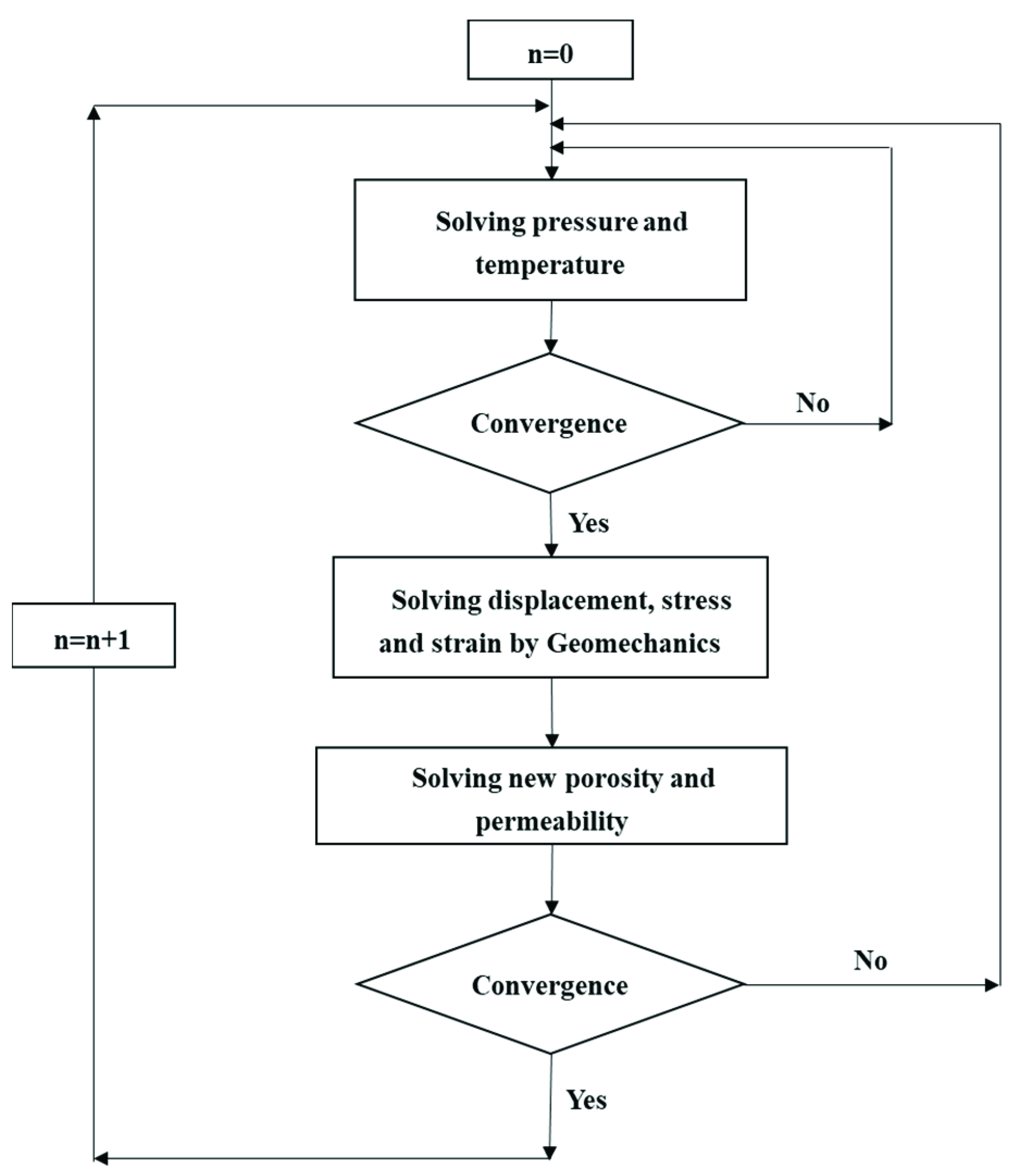
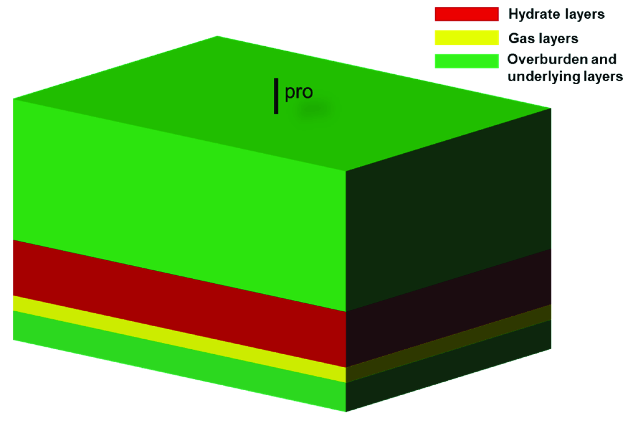
2. Methodology and Procedures

The numerical simulation approach is adopted to elucidate the depressurization production process. The reservoir simulator CMG STARS (v2015, Computational Modeling Group, Calgary, AB, Canada) was utilized to build the reservoir model and to perform all the scenarios discussed in this paper. The STARS (Steam Thermal and Advanced Process Reservoir Simulator) is a reservoir simulator developed by the Computational Modeling Group Ltd., primarily for modeling the flow of three phases in the form of multi-component fluids. It can be used to model compositional, seam, geomechanical, and dispersed components, and the in situ combustion process. SRATS uses a discretized wellbore model that improves the modeling by discretizing the wellbore and solving the resulting coupled wellbore and reservoir flow problem simultaneously. It can also handle the formation and decomposition of hydrates [32,33]. Therefore, CMG STARS is adopted in this paper to build a model of unconsolidated hydrate reservoirs in the South China Sea.
The model is simplified to be a cuboid, assuming that the overburdening and underlying rock layers are impermeable and that saturation, permeability, and porosity are considered homogeneous, which are different from the real and complicated reservoir. The simulation parameters were determined according to the production test conducted in the South China Sea [29] and are simplified to improve the calculation speed: the water depth is 1500 m, the buried depth is 120 m, and the underlying rock strata is 20 m. This model was 2280 m in length, 1600 m in width, and 200 m in thickness. There is a free gas layer under the hydrate-bearing layer. The non-consolidation is achieved through the Geomechanics module in STARS (Figure 1). Although hydrate decomposition temporarily increases the formation porosity, the overburdening rock layers will compact the sediments and decrease the porosity. Moreover, the formation strength will also decrease with hydrate decomposition by changing the cohesion value, which will lead to substantial formation subsidence. The Carmen–Kozeny formula was used to calculate permeability, according to porosity. The model is shown in Figure 2, with a vertical well in the center. The detailed parameters are listed in Table 1, below.
The model was verified by comparing it with the known data of trial production tests, and the distribution of formation subsidence after production was analyzed briefly.
Then, the numerical simulation approach can be divided into two steps, to determine the safe and efficient production methods for unconsolidated hydrate formations with various parameters.
Firstly, a series of scenarios were run in an attempt to analyze the sensitivity of gas production to different parameters, including formation parameters and production parameters. A vertical well was adopted for sensitivity analysis, except when considering the sensitivity regarding the horizontal length. All the scenarios in this paper were simulated for a production duration of 1100 days.
The formation parameters are defined once the target reservoir has been identified, and consist of buried depth, initial hydrate saturation, and formation porosity. The production parameters refer to the well type and the associated parameters that can be intentionally changed. There are two types of wells: vertical and horizontal. Bottom hole pressure is the most important parameter for vertical wells, while horizontal wells should be concerned with horizontal length. Moreover, heat injection can be used with depressurization to boost gas production to some extent in both well types.
In the sensitivity analysis, it was only the parameter to be analyzed that varied, while all the other parameters remained constant. Several groups of simulations were run for each parameter. The relationship curve between cumulative gas production and the parameter to be investigated was linearly fitted and the slopes of these lines were compared, to find out which parameters had the greatest influence on gas production.
Secondly, the appropriate well types and parameters were determined. According to exploration data in the South China Sea, the average porosity of hydrate reservoirs is approximately 40%, with hydrate saturation ranging from 10% to 40% [18,19]. However, hydrate sediments with 10% saturation are not considered promising targets for production [34] and are ignored in the subsequent simulations. A horizontal well and vertical well were adopted. Under various production parameters, cumulative gas production and formation subsidence were obtained. Finally, the appropriate methods and parameters for maximum cumulative gas production were selected, while not exceeding the safety subsidence for various hydrate reservoirs in the South China Sea, based on the various economic and safety concerns.

3. Results and Discussion

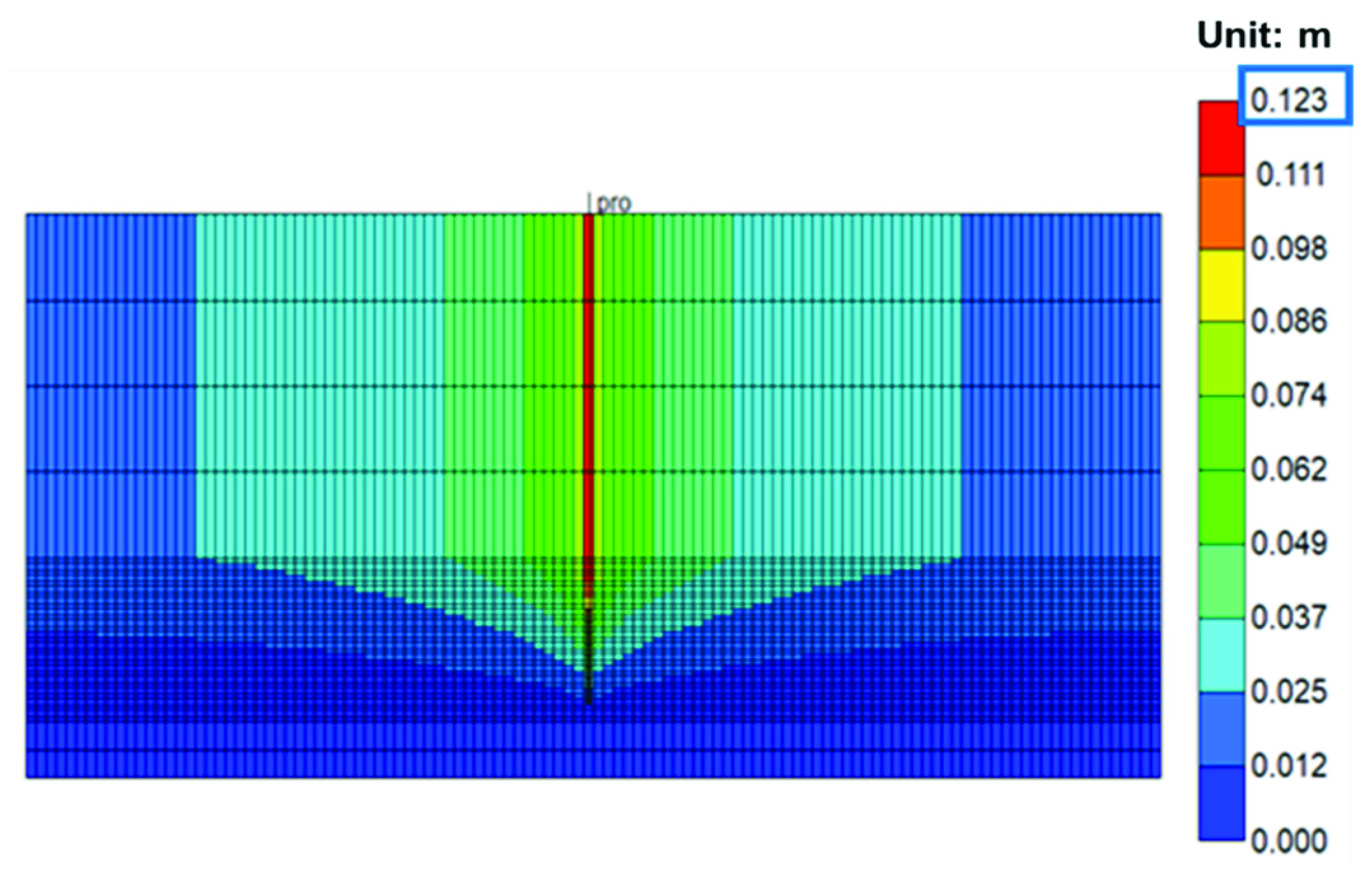
3.1. Formation Subsidence of Unconsolidated Hydrate Reservoirs during Production

Unconsolidated hydrate sediments will experience great subsidence during production. Until now, only Japan and China have conducted marine hydrate production tests. According to the trial production test of marine hydrates around the world, the first production test in Japan in 2013 lasted 6 days and was halted due to serious sand production. The monitored seafloor subsidence was 0.1 m to 0.3 m after depressurization, which was combined with heat-injection production [35]. There were no reference data for the formation subsidence of the production test in the South China Sea. Figure 3 shows the subsidence distribution of the unconsolidated hydrate sediments after depressurization production. The largest subsidence of 0.123 m (the blue box in Figure 3) occurred around the wellbore, which was close to the trial test value for Japan, meaning that the model and CMG simulator were feasible for predicting the geomechanical response. The distribution of subsidence was axisymmetric with the production well because hydrates near the well-bore decomposed first and the decomposition area extended outward gradually.

3.2. Sensitivity to Formation Parameters

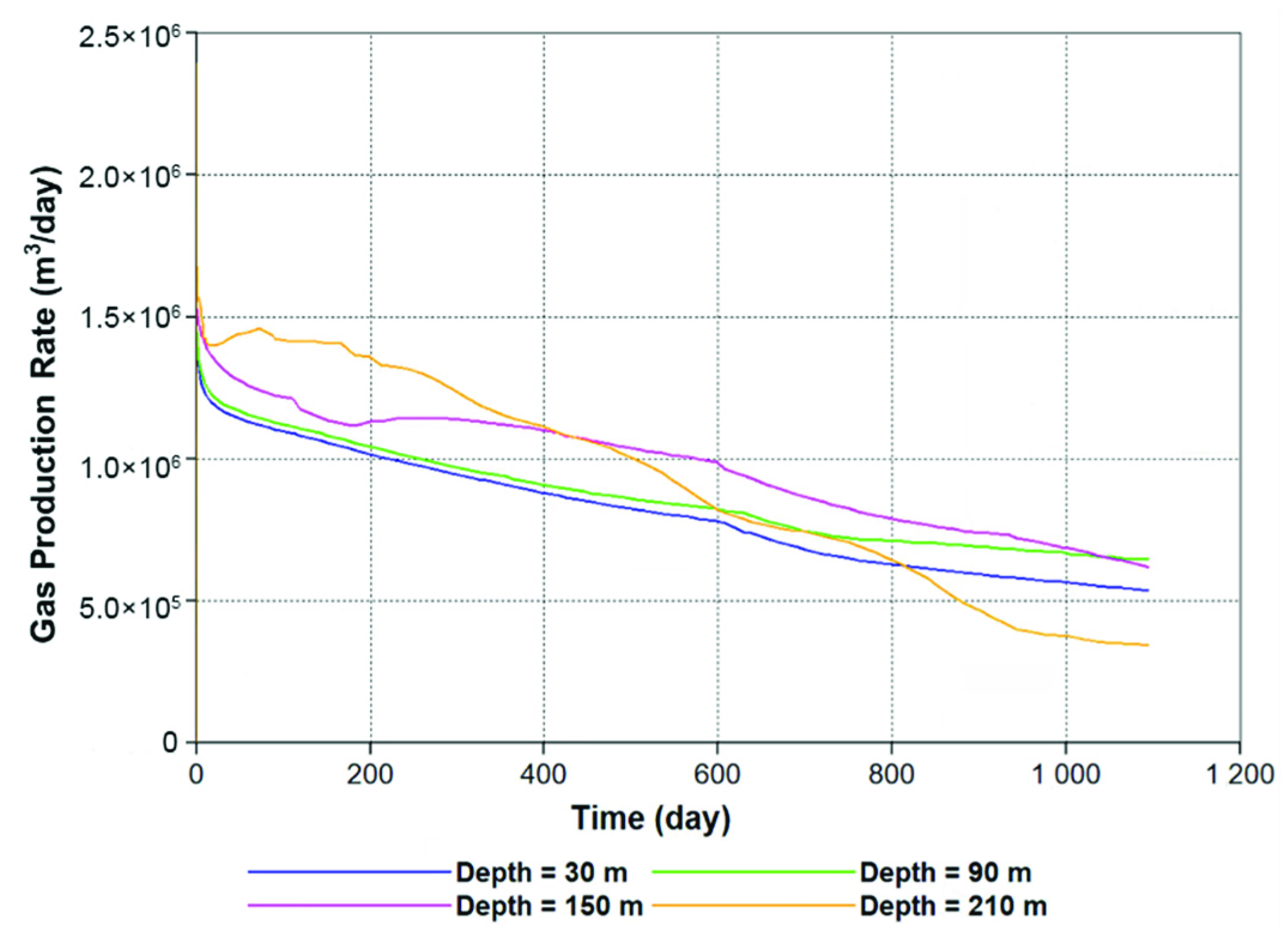
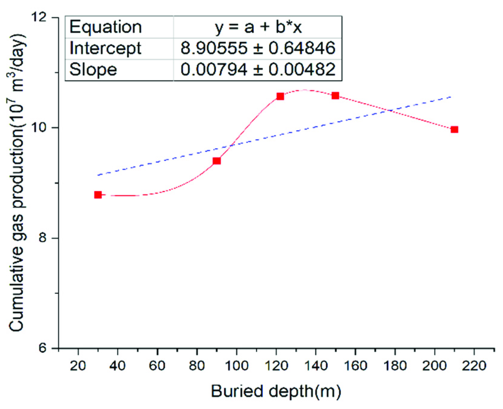
3.2.1. Effect of Buried Depth

As illustrated in Figure 4, at the beginning of production, the gas rate increased with the buried depth. The reason is that as the buried depth increases, the initial formation pressure rises, resulting in a larger production pressure differential. Thus, the hydrate decomposition rate would be higher. However, in the case of a deeply buried hydrate reservoir, the decomposition rate would decline dramatically over time, due to the rapid reduction of the residual hydrate, as shown by the yellow curve in Figure 4.
Figure 5 depicts the relationship between cumulative gas production and buried depth, which is roughly positive. The curve was linearly fitted, with a slope of 0.00794, indicating that the buried depth had a minor impact on gas production.

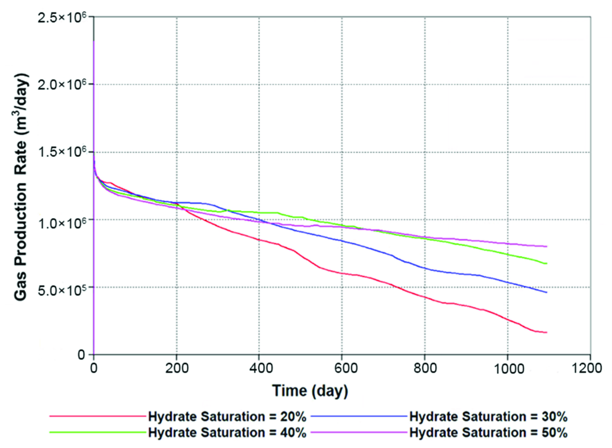
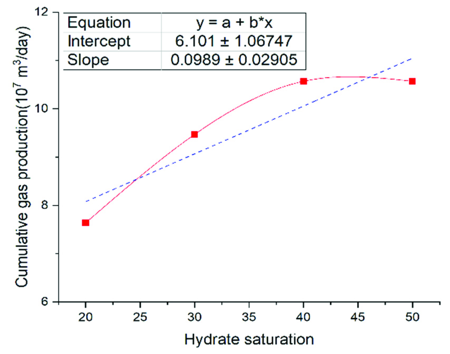
3.2.2. Effect of Hydrate Saturation

As shown in Figure 6, the gas production rate increases with the decrease in hydrate saturation (denoted by Sh below). As production progressed, the gas rate of the formation with a low Sh began to decline rapidly.
This is analogous to ice melting. The distribution of hydrate in the formation is dispersed in reservoirs with a low Sh. The hydrates will rapidly decompose and release methane once the formation pressure declines. Because there is not much hydrate remaining in the formation during the middle and late phases, the gas production rate will drop drastically. In the case of a reservoir with a high Sh, the distribution of hydrate in the formation is rather concentrated, the majority of it being massive. Only the outermost hydrate decomposes at a slow pace at the start of production. As time goes on, the hydrate progressively becomes more dispersed and gas production continues to rise, exceeding the rate of reservoirs with a low Sh.
Therefore, the influence of hydrate saturation on gas production varied, depending on the stages. Reservoirs with a low Sh could generate a large quantity of gas quickly, but the production duration was quite limited. While reservoirs with a high Sh had a long production duration, it required time to achieve significant gas production.
Figure 7 shows the relationship between cumulative gas production and Sh. The slope of the linearly fitted curve was 0.0989, indicating that Sh had a greater effect on gas production than buried depth.

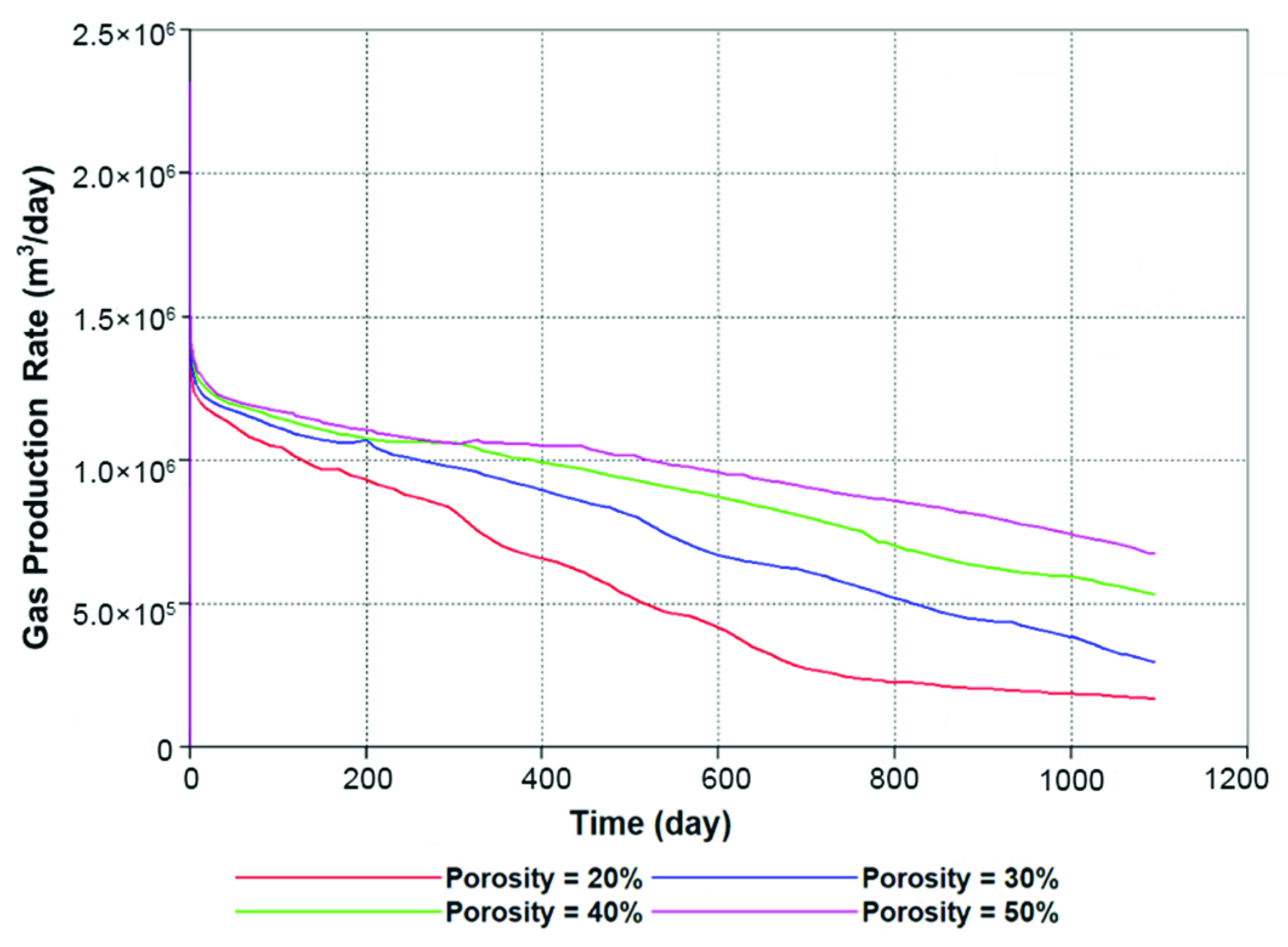
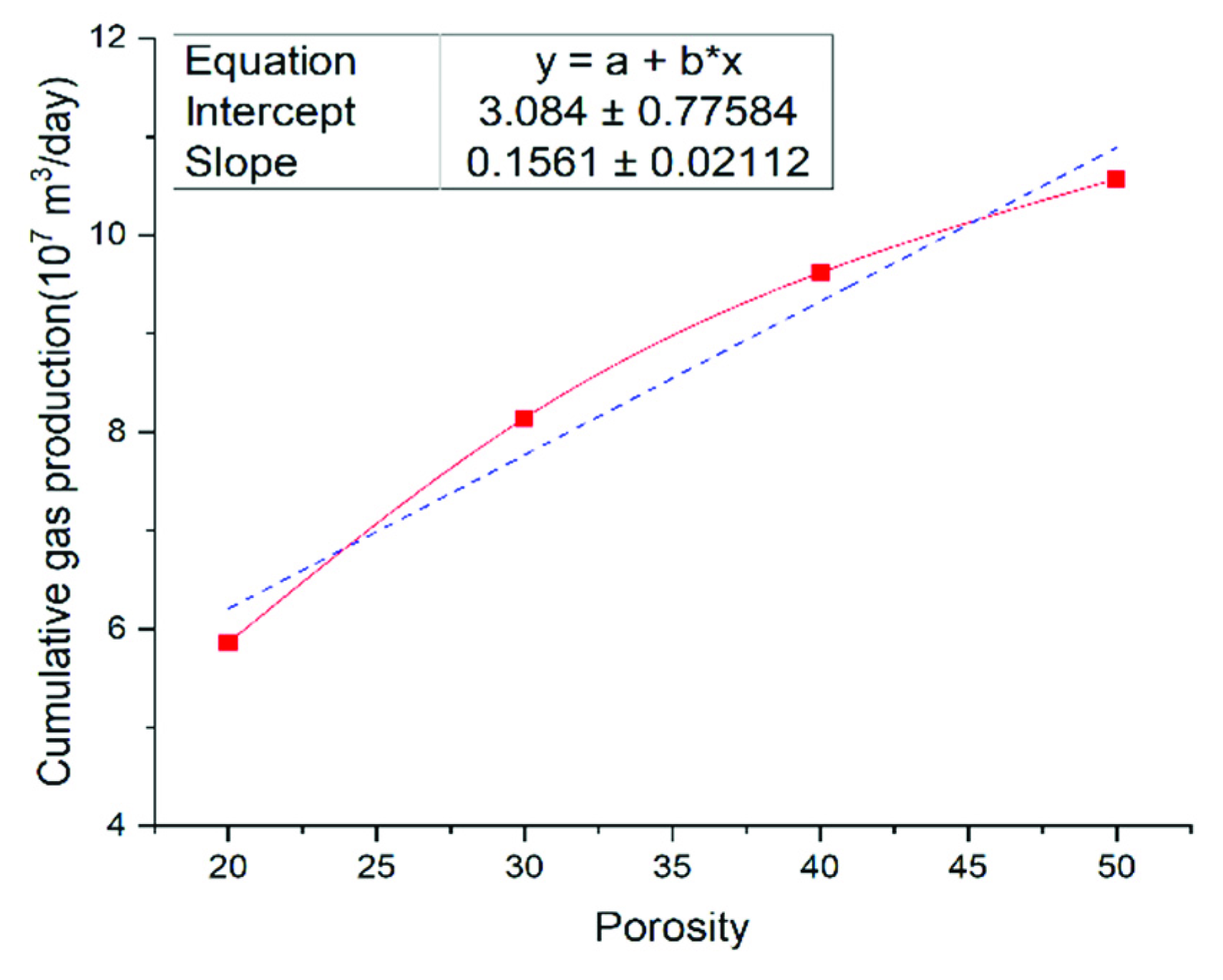
3.2.3. Effect of Formation Porosity

The larger the porosity (denoted by φ below), the faster the fluid flowed in the formation, and so the pressure drop spread quickly. As a result, the decomposition rate of hydrate would be faster and more gas would be produced. That is, the rate of gas production was proportional to φ , as shown in Figure 8.
The relationship between gas production and φ is seen in Figure 9. The slope of the curve was 0.1561, suggesting that φ had a greater impact on gas production than Sh.

3.3. Sensitivity to Production Parameters

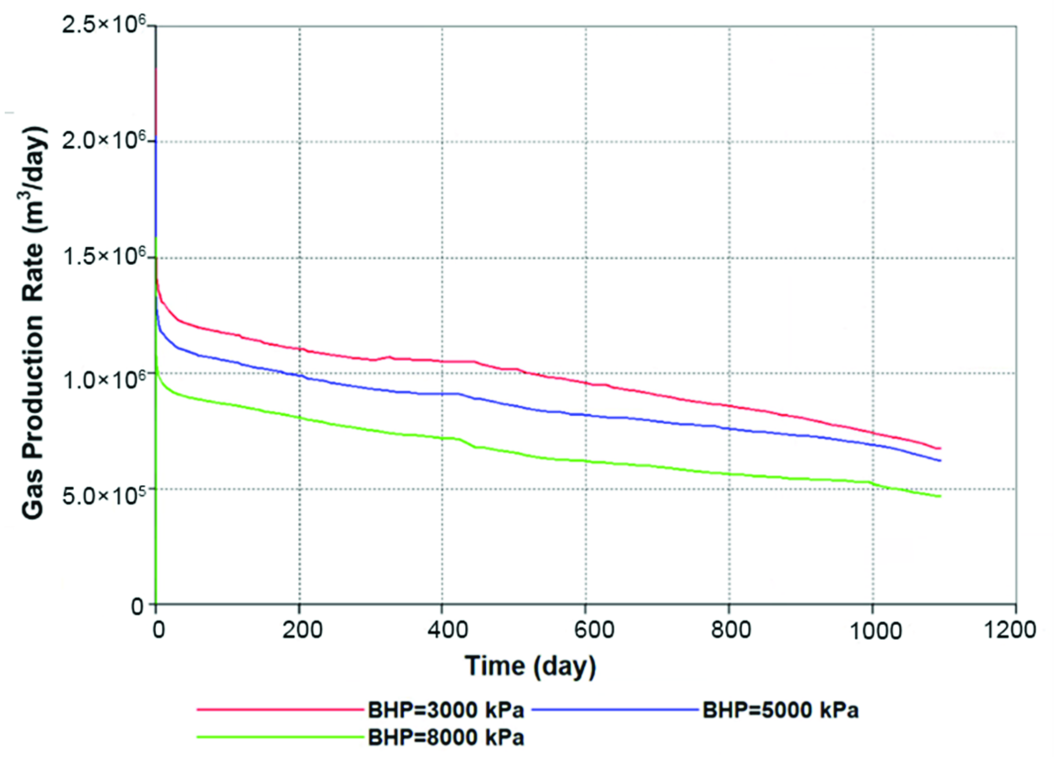
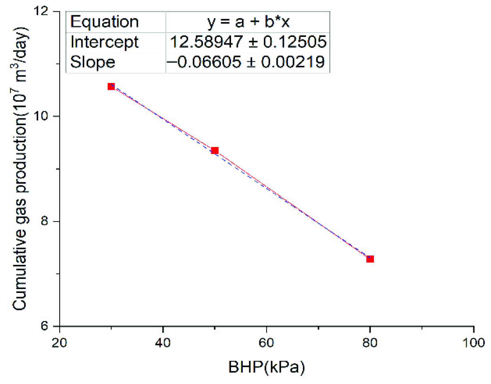
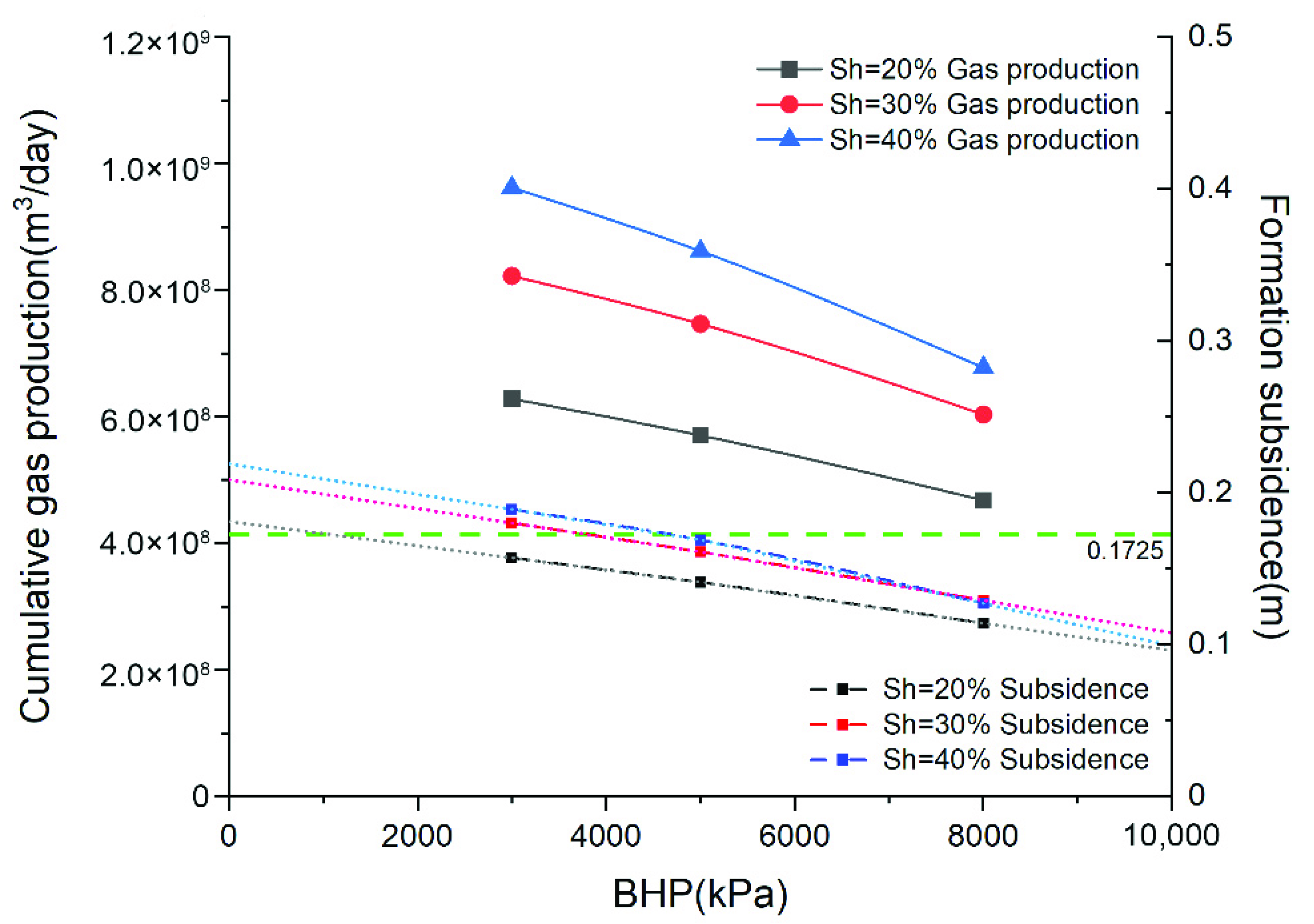
3.3.1. Effect of Bottom Hole Pressure

As shown in Figure 10, the gas rate is inversely proportional to BHP, which implies that if the safety aspect of production is ignored, gas production will increase with the decrease in BHP.
Figure 11 depicts the connection between gas production and BHP. The curve was linearly fitted, and the slope was −0.6605, indicating that BHP had a significant impact on gas production.

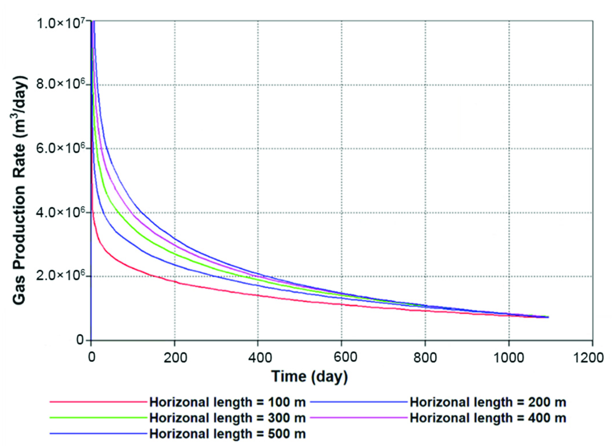
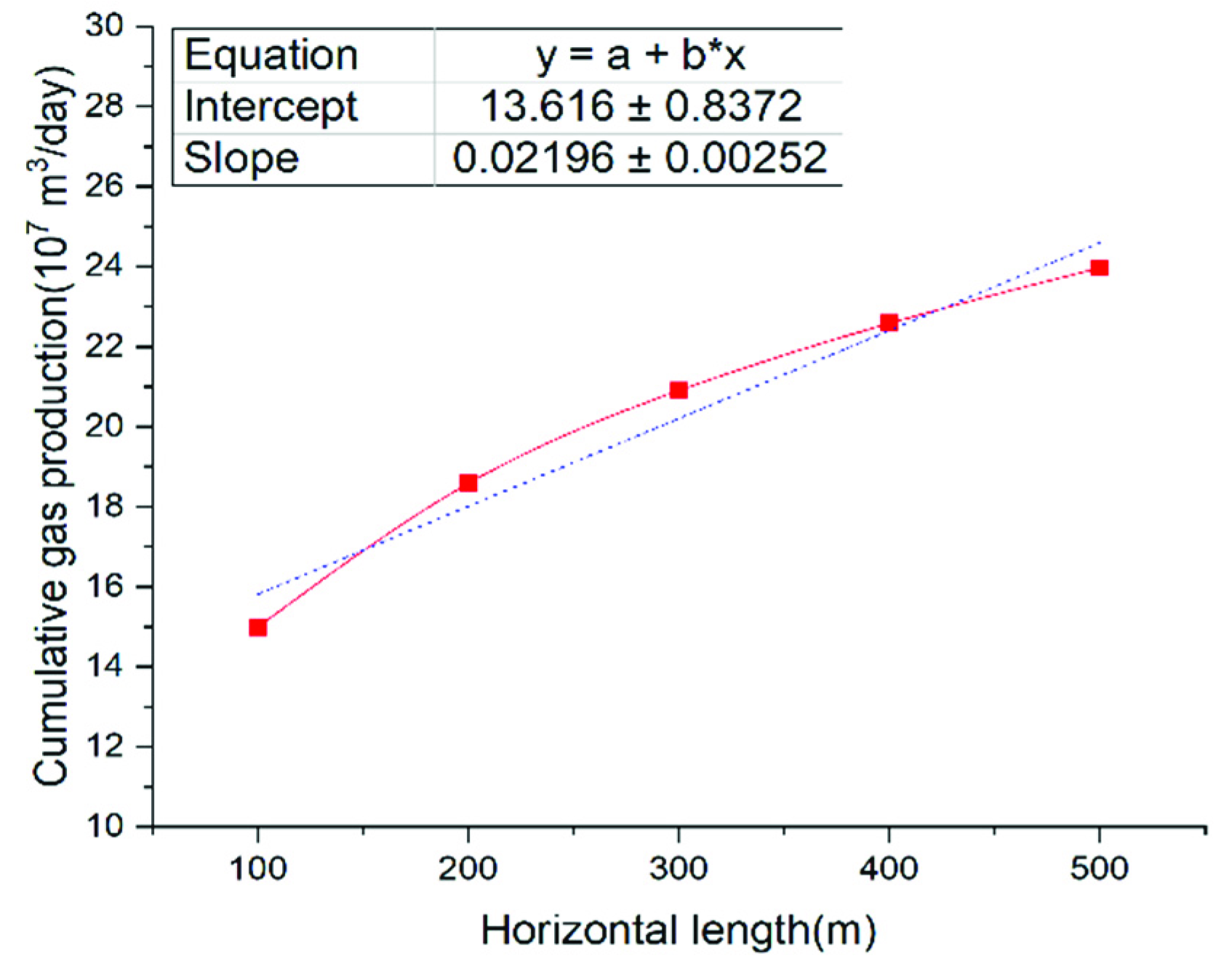
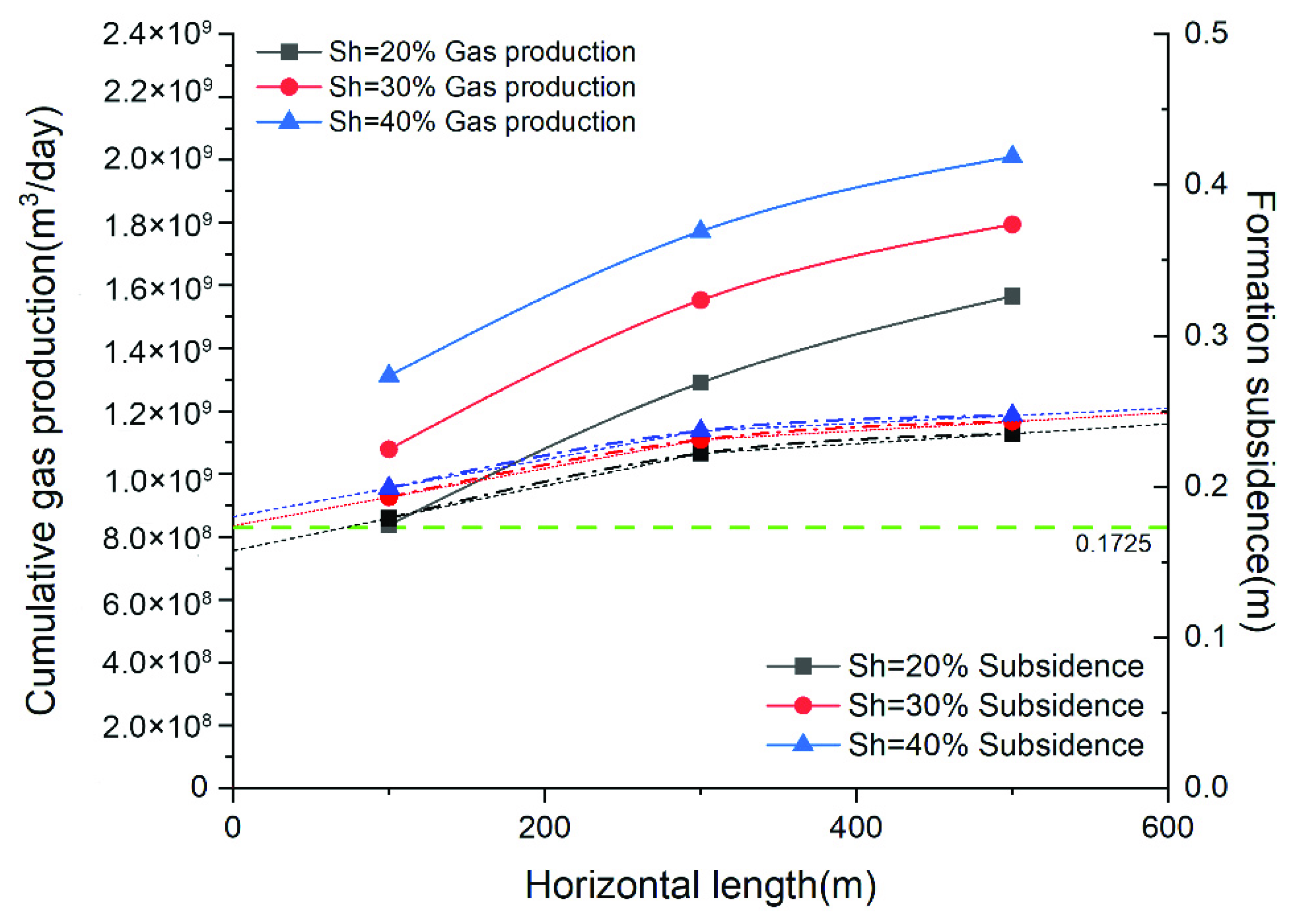
3.3.2. Effect of Horizontal Length

As shown in Figure 12, gas production increases with the horizontal length (denoted by L, below) due to the faster pressure drop propagation induced by the increase in the exposed surface.
Figure 13 displays the correlation between gas production and L. The slope of the curve was 0.02196, demonstrating that L had a great influence on gas production, although not as much as BHP.

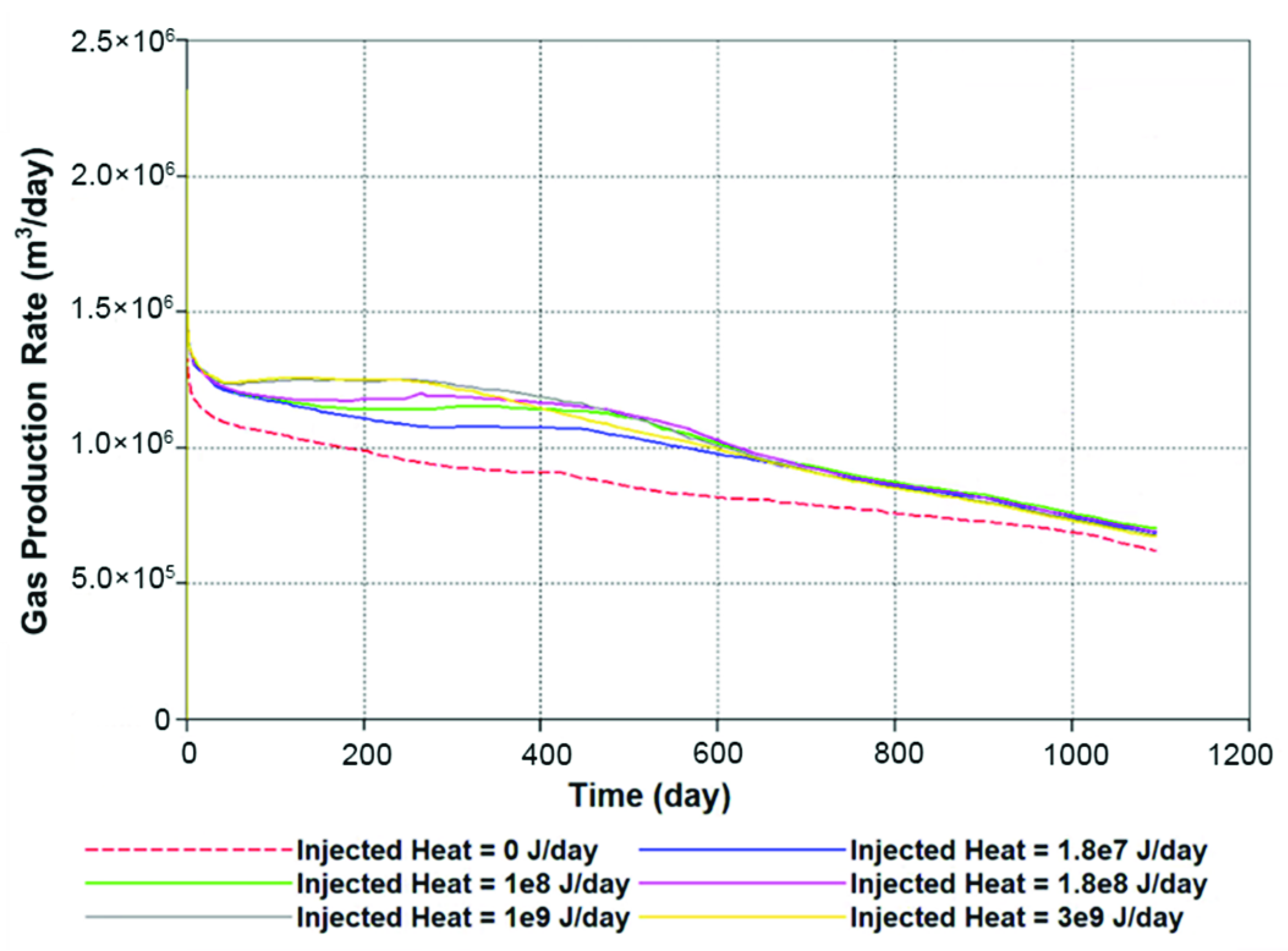
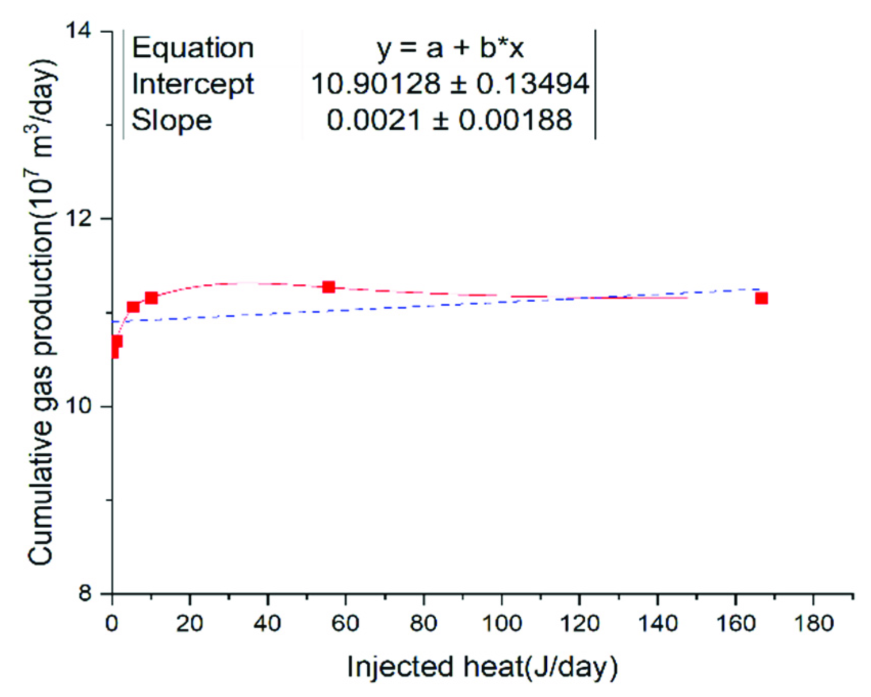
3.3.3. Effect of Injection Heat

As shown in Figure 14, injecting heat into the formation can boost the gas rate, albeit only slightly. When the injected heat surpassed a specific threshold (1 × 10⁹ J/day), the gas rate would decrease compared with the rate when there is no heat injection. In other words, within a specific range, the gas rate was positively correlated with heat injection.
Figure 15 shows the relationship between gas production and Q. The curve was linearly fitted with a slope of 0.0021, indicating that Q had a negligible impact on gas production.
Overall, when all other parameters were assumed to be constant, the sensitivity of gas production to formation parameters was as follows: formation porosity > hydrate saturation > buried depth. The impact of the production parameters was: BHP > horizontal length > injected heat, as shown in Table 2.

3.4. Appropriate Well Types and Parameters

Figure 16 and Figure 17 illustrate the simulation results of hydrate reservoirs of different saturations in the South China Sea. The solid line denotes cumulative gas production, whereas the dotted line represents formation subsidence. The different colors represent different hydrate saturations. Among the simulations in this paper, gas production and formation subsidence using a horizontal well were all higher than that of a vertical well. However, what we expect is maximum gas production with minimum formation subsidence. In order to achieve this goal, it is necessary to choose an appropriate well type. In addition, gas production and formation subsidence both increased with the decrease in bottom hole pressure when a vertical well was adopted, and both increased with the increase in horizontal length when a horizontal well was adopted. Therefore, a balance between gas production and formation subsidence must be determined. That is, the appropriate parameters for the selected well type must be determined to achieve high gas production and low formation subsidence. A safety formation subsidence figure is proposed in this paper to achieve the above objectives. The safety formation subsidence was set at 0.1725 m (the average of the maximum and minimum subsidence figures in all the simulations), as shown by the dotted green line in Figure 16 and Figure 17.
At this point, the appropriate parameters for different reservoirs could be determined. Figure 16 depicts the appropriate BHP for hydrate reservoirs with various saturation values when a vertical well was used. The subsidence of hydrate reservoirs with different saturations was lower than the safety formation subsidence under a range of BHPs. When the hydrate saturation was 20%, the BHP should be at least 1060 kPa; when hydrate saturation was 30%, the BHP should be at least 3800 kPa; and when hydrate saturation is 40%, the BHP should be at least 4800 kPa.
Figure 17 shows the critical horizontal length found when a horizontal well was adopted. When the hydrate saturation was 20%, the horizontal length should not exceed 80 m. The subsidence of hydrate reservoirs with 30% and 40% saturation exceeded the safety value, whatever the horizontal length of the well, which means that a horizontal well was unsuitable for these two reservoir schemes.
Table 3 summarizes the well type and the parameters suitable for hydrate reservoirs with different saturations. For a hydrate reservoir with a saturation of 20%, gas production using a horizontal well was higher than when using a vertical well. For a hydrate reservoir with a saturation of 30% and 40%, a vertical well was suitable because the subsidence when using a horizontal well exceeded the safety value.
The method offered in this paper to determine the suitable production parameters for gas production is worth using as a reference, but the values still need to be adjusted, based on the consideration of drilling and operation costs in trial production projects.

4. Conclusions

A series of simulations were conducted utilizing CMG software to elucidate the depressurization production process of marine gas hydrates in unconsolidated sediments. The sensitivity analysis showed that porosity and hydrate saturation were the formation parameters that had the greatest impact on gas production and could be used to determine the type of reservoir, while bottom hole pressure and horizontal length were the production parameters that should be optimized for safe and efficient production. Based on economic and safety concerns, the appropriate production methods with the highest cumulative gas production and lowest subsidence for different hydrate reservoirs were determined. When hydrate saturation is 20%, a horizontal well is suitable, and the appropriate horizontal length is less than 80 m. When hydrate saturation is 30% or 40%, a vertical well is suitable, and the appropriate bottom hole pressure is no less than 3800 kPa and 4800 kPa for 30% and 40% saturation, respectively. However, the safety formation subsidence rate is determined merely according to the simulation results in this paper, which need to be adjusted considering other factors in the future, such as the tension on production equipment, the properties of seafloor soils, the operation costs, and so on.

Author Contributions

Conceptualization, Y.C. and T.S.; methodology, Y.C.; validation, S.J.; writing—original draft preparation, Y.C.; writing—review and editing, S.W.; supervision, S.W., T.S.; funding acquisition, S.W. All authors have read and agreed to the published version of the manuscript.

Funding

This research was funded by the Specific Research Fund of the Innovation Platform for Academicians of Hainan Province, grant number No. YSPTZX202204, the Sanya Yazhou Bay Science and Technology City Program, grant number NO. SKJC-2020-01-009, Hainan Provincial Major Science and Technology Program of China, grant number No. ZDKJ202019, and National Key Research and Development Program of China, grant number No. 2019YFC0312301.

Institutional Review Board Statement

Not applicable.

Informed Consent Statement

Not applicable.

Data Availability Statement

All data generated or analyzed during this study are included in this published article.

Acknowledgments

This study was funded by the Specific Research Fund of the Innovation Platform for Academicians of Hainan Province, grant number (No. YSPTZX202204), the Sanya Yazhou Bay Science and Technology City Program (NO. SKJC-2020-01-009), the Hainan Provincial Major Science and Technology Program of China (No. ZDKJ202019), and the National Key Research and Development Program of China (No. 2019YFC0312301).

Conflicts of Interest

The authors declare no conflict of interest.

References

  1. Sloan, E.D.; Koh, C.A. lathrate Hydrates of Natural Gases, 3rd ed.; CRC Press: Boca Raton, FL, USA, 2008; pp. 1–5. [Google Scholar]
  2. Moridis, G.J.; Collett, T.S.; Pooladi-Darvish, M.; Hancock, S.H.; Santamarina, C.; Boswell, R.; Kneafsey, T.J.; Rutqvist, J.; Kowalsky, M.B.; Reagan, M.T.; et al. Challenges, Uncertainties, and Issues Facing Gas Production From Gas-Hydrate Deposits. SPE Reserv. Evaluation Eng. 2011, 14, 76–112. [Google Scholar] [CrossRef] [Green Version]
  3. Yuan, Y.L. Numerical Simulation of Exploitation Potential and Mechanical Stability of Marine Natural Gas Hydrate Depressurization. Ph.D. Thesis, Jilin University, Changchun, China, 2019. [Google Scholar]
  4. Hassanpouryouzband, A.; Joonaki, E.; Farahani, M.V.; Takeya, S.; Ruppel, C.; Yang, J.; English, N.J.; Schicks, J.M.; Edlmann, K.; Mehrabian, H.; et al. Gas hydrates in sustainable chemistry. Chem. Soc. Rev. 2020, 49, 5225–5309. [Google Scholar] [CrossRef]
  5. Ruan, X.; Li, X.-S.; Xu, C.-G. A review of numerical research on gas production from natural gas hydrates in China. J. Nat. Gas Sci. Eng. 2020, 85, 103713. [Google Scholar] [CrossRef]
  6. Zander, T.; Choi, J.C.; Vanneste, M.; Berndt, C. Potential Impacts of Gas Hydrate Exploitation on Slope Stability—A Study from the Danube Fan, Black SEA. In Proceedings of the Near Surface Geoscience 2016-Second Applied Shallow Marine Geophysics Conference, Barcelona, Spain, 4–8 September 2016. [Google Scholar] [CrossRef] [Green Version]
  7. Matsuda, H.; Yamakawa, T.; Sugai, Y.; Sasaki, K. Gas Production from Offshore Methane Hydrate Layer and Seabed Subsidence by Depressurization Method. Engineering 2016, 8, 353–364. [Google Scholar] [CrossRef] [Green Version]
  8. Hyodo, M.; Li, Y.; Yoneda, J.; Nakata, Y.; Yoshimoto, N.; Nishimura, A. Effects of dissociation on the shear strength and deformation behavior of methane hydrate-bearing sediments. Mar. Pet. Geol. 2014, 51, 52–62. [Google Scholar] [CrossRef]
  9. Hyodo, M.; Yoneda, J.; Yoshimoto, N.; Nakata, Y. Mechanical and dissociation properties of methane hydrate-bearing sand in deep seabed. Soils Found. 2013, 53, 299–314. [Google Scholar] [CrossRef] [Green Version]
  10. Grover, T.; Holditch, S.A.; Moridis, G. Analysis of Reservoir Performance of Messoyakha Gas Hydrate Field. In Proceedings of the Eighteenth International Offshore and Polar Engineering Conference, Vancouver, BC, Canada, 6 July 2008. [Google Scholar] [CrossRef]
  11. Moridis, G.J.; Collett, T.S.; Dallimore, S.R.; Satoh, T.; Hancock, S.; Weatherill, B. Numerical studies of gas production from several CH4 hydrate zones at the Mallik site, Mackenzie Delta, Canada. J. Pet. Sci. Eng. 2004, 43, 219–238. [Google Scholar] [CrossRef] [Green Version]
  12. Yamamoto, K.; Dallimore, S. Aurora-JOGMEC-NRCan Mallik 2006–2008 gas hydrate research project progress. Nat. Gas Oil 2008, 304, 285–4541. [Google Scholar]
  13. Collett, T.S.; Boswell, R.; Lee, M.W.; Anderson, B.J.; Rose, K.; Lewis, K.A. Evaluation of Long-Term Gas Hydrate Production Testing Locations on the Alaska North Slope. SPE Reserv. Eval. Eng. 2012, 15, 243–264. [Google Scholar] [CrossRef]
  14. Boswell, R. Japan completes first offshore methane hydrate production test—methane successfully produced from deepwater hydrate layers. Cent. Nat. Gas Oil 2013, 412, 386–7614. [Google Scholar]
  15. Konno, Y.; Fujii, T.; Sato, A.; Akamine, K.; Naiki, M.; Masuda, Y.; Yamamoto, K.; Nagao, J. Key Findings of the World’s First Offshore Methane Hydrate Production Test off the Coast of Japan: Toward Future Commercial Production. Energy Fuels 2017, 31, 2607–2616. [Google Scholar] [CrossRef]
  16. Zhou, S.; Zhao, J.; Li, Q.; Chen, W.; Zhou, J.; Wei, N.; Guo, P.; Sun, W. Optimal design of the engineering parameters for the first global trial production of marine natural gas hydrates through solid fluidization. Nat. Gas Ind. B 2018, 5, 118–131. [Google Scholar] [CrossRef]
  17. Li, J.-F.; Ye, J.-L.; Qin, X.-W.; Qiu, H.-J.; Wu, N.-Y.; Lu, H.-L.; Xie, W.-W.; Lu, J.-A.; Peng, F.; Xu, Z.-Q.; et al. The first offshore natural gas hydrate production test in South China Sea. China Geol. 2018, 1, 5–16. [Google Scholar] [CrossRef]
  18. Ye, J.L.; Qin, X.W.; Xie, W.W.; Lu, H.L.; Ma, B.J.; Qiu, H.J.; Bian, H. The second natural gas hydrate production test in the South China Sea. China Geol. 2020, 3, 197–209. [Google Scholar] [CrossRef]
  19. Li, S. Numerical simulation of gas hydrate depressurization and thermal injection in mining process. Master’s Thesis, Harbin Engineering University, Harbin, China, 2017. [Google Scholar]
  20. Merey, S.; Sinayuc, C. Numerical simulations for short-term depressurization production test of two gas hydrate sections in the Black Sea. J. Nat. Gas Sci. Eng. 2017, 44, 77–95. [Google Scholar] [CrossRef]
  21. Chen, C.; Yang, L.; Jia, R.; Sun, Y.; Guo, W.; Chen, Y.; Li, X. Simulation Study on the Effect of Fracturing Technology on the Production Efficiency of Natural Gas Hydrate. Energies 2017, 10, 1241. [Google Scholar] [CrossRef]
  22. Zheng, R.C.; Yin, Z.; Khoo, B.C.; Linga, P. E Enhanced Gas Recovery from Water Saturated Hydrate Bearing Sediments Using Horizontal Wellbore. In Proceedings of the Offshore Technology Conference Asia, Kuala Lumpur, Malaysia, 20 March 2018. [Google Scholar] [CrossRef]
  23. Zhang, P.; Tian, S.; Zhang, Y.; Li, G.; Zhang, W.; Khan, W.A.; Ma, L. Numerical simulation of gas recovery from natural gas hydrate using multi-branch wells: A three-dimensional model. Energy 2020, 220, 119549. [Google Scholar] [CrossRef]
  24. Jin, G.; Xu, T.; Xin, X.; Wei, M.; Liu, C. Numerical evaluation of the methane production from unconfined gas hydrate-bearing sediment by thermal stimulation and depressurization in Shenhu area, South China Sea. J. Nat. Gas Sci. Eng. 2016, 33, 497–508. [Google Scholar] [CrossRef]
  25. Feng, J.-C.; Li, X.; Li, G.; Li, B.; Chen, Z.-Y.; Wang, Y. Numerical Investigation of Hydrate Dissociation Performance in the South China Sea with Different Horizontal Well Configurations. Energies 2014, 7, 4813–4834. [Google Scholar] [CrossRef] [Green Version]
  26. Gong, B.; Jiang, Y.J.; Wang, G.; Huang, N. Prediction of seabed subsidence from gas hydrate exploitation in the South China Sea. J. Shandong Univ. Sci. Technol. Nat. Sci. 2015, 34, 61–68. [Google Scholar] [CrossRef]
  27. Wan, Y.Z.; Wu, N.Y.; Hu, G.W.; Xin, X.; Jin, G.R.; Liu, C.L.; Chen, Q. Reservoir stability during gas hydrate depressurization exploitation in Shenhu area, South China Sea. Nat. Gas Ind. 2018, 38, 117–128. (In Chinese) [Google Scholar] [CrossRef]
  28. Jin, G.; Lei, H.; Xu, T.; Xin, X.; Yuan, Y.; Xia, Y.; Juo, J. Simulated geomechanical responses to marine methane hydrate recovery using horizontal wells in the Shenhu area, South China Sea. Mar. Pet. Geol. 2018, 92, 424–436. [Google Scholar] [CrossRef]
  29. Li, L.L.; Yang, J.; Lu, B.P.; Ke, K.; Wang, L.; Chen, K.J. Research on stratum settlement and wellhead stability in deep water during hydrate production testing. Pet. Drill. Tech. 2020, 48, 61–68. (In Chinese) [Google Scholar] [CrossRef]
  30. Lee, T.; Lee, J.Y.; Ahn, T.; Son, H.A. Numerical Simulation of Gas Hydrate Production Using the Cyclic Depressurization Method in the Ulleung Basin of the Korea East Sea. Appl. Sci. 2021, 11, 9748. [Google Scholar] [CrossRef]
  31. Sun, J.; Wu, S.G.; Zhu, L.Q.; Liu, Y.R.; Sun, Z.Y. Characteristics and influencing factors of seabed subsidence in gas hydrate depressions mining. J. Cent. South Univ. Sci. Technol. 2022, 53, 1033–1046. [Google Scholar]
  32. Chaves, G. Simulation of CO2 sequestration in deep saline aquifers. Master’s Thesis, New Mexico Institute of Mining and Technology, Socorro, NM, USA, 2011. [Google Scholar]
  33. Janicki, G.; Schlüter, S.; Hennig, T.; Lyko, H.; Deerberg, G. Simulation of Methane Recovery from Gas Hydrates Combined with Storing Carbon Dioxide as Hydrates. J. Geol. Res. 2011, 2011, 1–15. [Google Scholar] [CrossRef] [Green Version]
  34. Moridis, G.J.; Sloan, E.D. Gas production potential of disperse low-saturation hydrate accumulations in oceanic sediments. Energy Convers. Manag. 2007, 48, 1834–1849. [Google Scholar] [CrossRef] [Green Version]
  35. Yokoyama, T.; Shimoyama, M.; Matsuda, S.; Tago, K.; Takeshima, J.; Nakatsuka, Y. Monitoring system of seafloor subsidence for methane hydrate production test. In Proceedings of the SPWLA 18th Formation Evaluation Symposium of Japan, Chiba, Japan, 27 September 2012. [Google Scholar]
Figure 1. Flow chart of the iterative calculation of the coupled geomechanics module.
Energies 15 04796 g001
Figure 2. Diagram of the production model of unconsolidated hydrate-bearing strata in the deep-water basin.
Energies 15 04796 g002
Figure 3. The subsidence distribution of unconsolidated hydrate formation during depressurization.
Energies 15 04796 g003
Figure 4. Gas production rates of various buried depths.
Energies 15 04796 g004
Figure 5. Relationship between cumulative gas production and buried depth.
Energies 15 04796 g005
Figure 6. Gas production rates of various hydrate saturations.
Energies 15 04796 g006
Figure 7. Relationship between cumulative gas production and hydrate saturations.
Energies 15 04796 g007
Figure 8. Gas production rates of various formation porosities.
Energies 15 04796 g008
Figure 9. Relationship between cumulative gas production and the formation porosities.
Energies 15 04796 g009
Figure 10. Gas production rates at different bottom-hole pressures.
Energies 15 04796 g010
Figure 11. Relationship between cumulative gas production and bottom hole pressures.
Energies 15 04796 g011
Figure 12. Gas production rates at different horizontal lengths.
Energies 15 04796 g012
Figure 13. The relationship between cumulative gas production and horizontal length.
Energies 15 04796 g013
Figure 14. Gas production rates under different heat injection specifications.
Energies 15 04796 g014
Figure 15. The relationship between cumulative gas production and injected heat.
Energies 15 04796 g015
Figure 16. Cumulative gas production and formation subsidence, using vertical wells.
Energies 15 04796 g016
Figure 17. Cumulative gas production and formation subsidence, using horizontal wells.
Energies 15 04796 g017
Table 1. Simulation parameters.
ParametersValue
Initial temperature, °C20
Initial pressure, kPa19,000
Thickness of hydrate, m50
Thickness of underlying gas, m10
Initial hydrate saturation0.4
Initial water saturationHydrate layer = 0.6
Underlying gas layer = 0.5
Initial gas saturationHydrate layer = 0
Underlying gas layer = 0.1
Porosity0.4
Permeability, Mdki = kj = kk = 0.1
Gas composition100% CH4
Thermal conductivity of the sediments, J/(m·day·C)1.728 × 105 (constant)
Yield criterionMohr-Coulomb
Initial cohesion, kPa850
Elasticity modulus, kPa3.6 × 106
Poisson’s ration0.35
Table 2. Summary of sensitivity analysis.
ParametersThe SlopeGas Production Sensitivity to the Parameters
Formation parametersFormation porosity0.1561Formation porosity > hydrate saturation > buried depth
Hydrate saturation0.0989
Buried depth0.00794
Production parametersBHP−0.6605BHP > horizontal length > injected heat
Horizontal length0.02196
Injected heat0.0021
Table 3. Methods and parameters that are suitable for various hydrate reservoirs.
PorosityHydrate SaturationProduction MethodProduction ParametersCritical Gas Production
40%20%Horizontal wellL ≤ 80 m7.7 × 108 m3/day
30%Vertical well 7.92 × 10⁸ m3/day
BHP ≥ 3800 kPa
40%Vertical well 8.7 × 10⁸ m3/day
BHP ≥ 4800 kPa
Publisher’s Note: MDPI stays neutral with regard to jurisdictional claims in published maps and institutional affiliations.

