Article

Traumatic Impact Assessment of CPR Load on a Human Ribcage

by
Luis Antonio Aguilar-Pérez
1,
Christopher René Torres-SanMiguel
1,*,
Marco Ceccarelli
2 and
Guillermo Manuel Urriolagoitia-Calderón
1
1
Instituto Politécnico Nacional, Escuela Superior de Ingeniería Mecánica y Eléctrica, Sección de Estudios de Posgrado e Investigación, Unidad Zacatenco, Mexico City 07738, Mexico
2
Laboratory of Robot Mechatronics, Department of Industrial Engineering, University of Rome Tor Vergata, 00133 Rome, Italy
*
Author to whom correspondence should be addressed.
Int. J. Environ. Res. Public Health 2022, 19(6), 3414; https://doi.org/10.3390/ijerph19063414
Submission received: 27 December 2021 / Revised: 5 March 2022 / Accepted: 7 March 2022 / Published: 14 March 2022
(This article belongs to the Special Issue The Evolving Role of Diagnostic Imaging Service in Public Health)

Abstract

:
Chest compression is a parameter of injury criteria assessment for human beings. Additionally, it is used to find the external compression response as a result of vehicle crashes, falls, or sporting impacts. This behavioral feature is described by many deterministic models related to specific experimental tests, hindering distinct scenarios. The present study evaluates the energy absorbed as a function of rib compression. The proposed model was obtained from three different computed tomography (CT) studies. The anthropometric values are interpolated to obtain a parametric curve for a human rib’s average size. The computed results are compared against an STL-DICOM® file used to obtain a virtual reconstruction of one rib. A numerical model of the behavior of the thorax displacement expressed injury in the human rib model’s stiffness. The proposed model is used to determine the correlation of the input payload versus the numerical stiffness value. The outcome is confirmed by numerical analyses applied to a virtual human rib reconstruction.

1. Introduction

One of the essential parts of a human being is the thorax. The ribcage’s primary function is to protect the internal soft tissues from local injuries and over-compressions applied to this area. Thorax injury severity has been summarized as a comparative of biomechanical parameters, such as displacements against traumatic events reported by medical professionals [1]. Human chest compression represented by 33.3% of the length causes failure in the patient’s thorax, fractures on both sides, or even pneumothorax or hemothorax. The injury criterion [2] combines statistical data that correlates the probability of this kind of damage in the human body with the physical variables related to the traumatic event. Several criteria, such as those previously addressed in this paper, comparatively classify systems according to an abbreviated injury scale 3+ (AIS), ranging from medium to dangerous, if the frontal compression exceed specific values. For example, the compression criteria indicate that the total compression must always be below 52 mm [3]. The criteria report that, upon collision, the thorax can experience force values below 3.3 kN [3]. The thorax’s injuries can be reproduced in laboratory conditions through artificial surrogates, biological surrogates, or computational simulations. The development of artificial test devices substitutes biological elements in the laboratory for real conditions, even if some random parameters cannot be evaluated. For example, through Dead Human Surrogates (DHSs) it can estimate the physical responses for wide ranges of events, including parameters like cardiopulmonary pressure, the natural degradation of tissues, or even the absence of muscular tension that causes a variation in almost 20% of the results [4,5,6]. In the same way, anthropometric test devices (ATDs) can then reproduce those results to confirm the initial behavior of these devices. Thus, the natural geometry complexity of the ribs can be overestimated in relation to the real injuries sustained by the thorax. The Hybrid III model’s biomechanical response, described by [5], reports a value four times higher than the real one’s stiffness. Perz in [7] noted that, in almost 40% of cases, most of the models overestimate the inertia values of different components that replicate the thorax’s behavior. In this way, the device’s reliability must be tuned to the real mechanical properties of durability and repeatability. Bone stiffness can be described as the strength of the entire bone structure, but, on the other hand, material stiffness is defined as the ability to oppose a mechanical load, such as compression or bending. This can be changed by material properties, the element’s geometry, and the boundary conditions used during the analysis. Moreover, in material engineering, the property used to oppose fracture propagation is known as tenacity, but these parameters can be overestimated in brittle materials, such as the bone. The human thorax in relation to ATDs tries to reproduce the ribs’ mechanical properties, vertebrae, breastbone, and cartilages using common materials, such as steel, plastic, or foam, with simplified geometries and standard cross transversal sections.
This paper evaluates the human rib’s complex geometry by developing a standard model that considers the element’s material properties and inertia values. The comparative results are used as validation criteria for the developed model. Once this numerical model is confirmed, a correlation between the payload is applied for one rib versus the rib stiffness computed from the numerical model. Finally, the computed model develops a dummy training system for educational purposes.

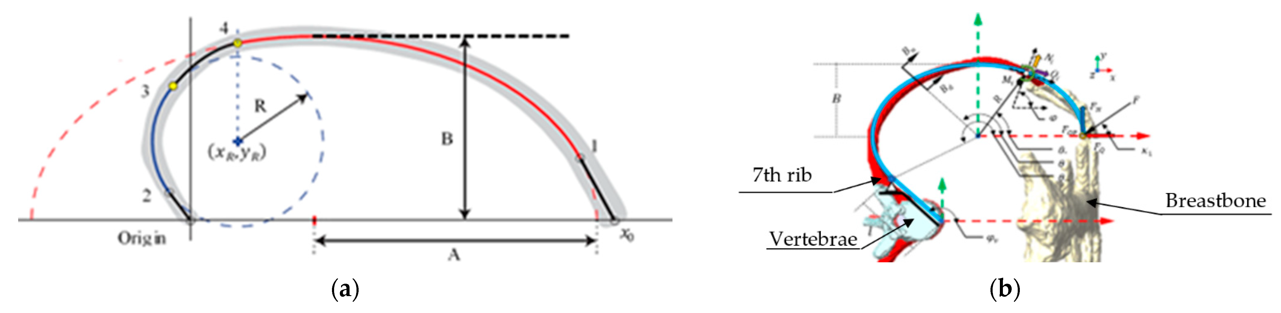
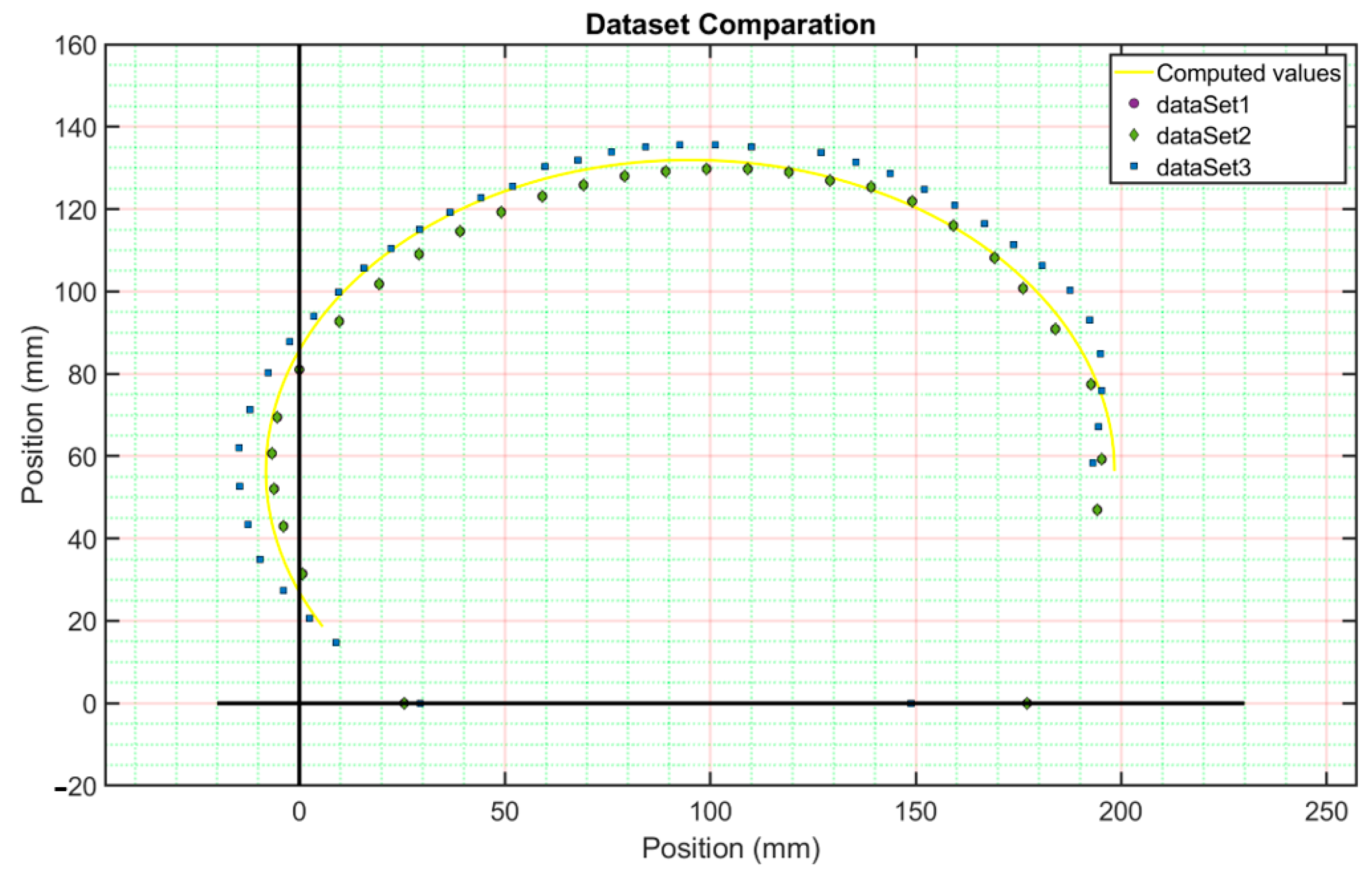
2. Materials and Methods

The human rib’s mechanical stiffness is a design parameter for artificial human ribs used by artificial surrogates. The proposed method uses a second-grade geometric curve computed through a dataset. The second-grade geometric curve was used as a guideline in a CAD sweep operation. Table 1 summarizes the entire dataset used alongside this work. All the data used here were obtained from the corresponding test subjects through letters of informed consent and anonymized through our research institution’s internal procedure.
Reference [8] reported the procedure to obtain the guideline curvature of the rib. Figure 1 compares both models to describe the reconstructed guideline curvature of the rib.
The main improvement of this model is that the entire guideline curvature is interpolated by a parametric curve. In addition, the proposed model includes a rib variation of its cross-section extensively described in [9] and mathematically explained in [10]. The second-grade curve is defined by the curvature of the rib as follows:
A x 2 + 2 B x y + C y 2 + 2 D x + 2 F y + G = 0
where the letters “A, B, C, D, F” and “G” are the constants computed by
E = [ B   C   D   F   G ] = M x 2  
M = [ 2 x y y 2 2 x 2 y 1 ]
These parameters are substituted into the general ellipse form as follows:
( x h 2 B ) 2 + ( y k 2 A ) 2 = 0 ,
where
h = ( C D B F ) B 2 A C ; k = ( A F B D ) B 2 A C
Then, the radius of the curvature is solved by:
r = B 2 ( B 2 A 2 1 ) cos 2 ( θ ) + 1   ,
On the other hand, the cross-section of the rib is described by the following:
T s e c t = [ d m e n sin ( θ ) D m a y cos ( θ ) 0 ] ,
By using the previous equations, the deformation of the rib is computed as follows:
U T = U N + U S + U M + U M N ,
where
U N = 0 7 π 6 B F Q 2 sin 2 ( θ ) 2 A a r e a E b o n e r   d θ
U S = 0 7 π 6 B F Q 2 k cos 2 ( θ ) 2 A a r e a G b o n e r   d θ
U M = 0 7 π 6 B 2 F Q 2 ( cos ( θ ) 1 ) 2 2 I x x E b o n e ( ( B 2 A 2 1 ) cos 2 ( θ ) + 1 ) d θ
U M N = 0 7 π 6 B F Q sin ( θ ) ( cos ( θ ) 1 ) A a r e a E b o n e r d θ
The rib stiffness is found as reference [11], where the linear spring constant relation can approximate the load deflection of a body, kStiffness. Then, the magnitude of the energy that a body can absorb is a function of its elongation, “δ”. Additionally, in reference [12], the main effects of the rib’s material properties are mentioned under injury conditions. For example, when testing a rib with no fractures, it was observed that the yield stress was around 69.64 MPa, but when a rib had a fracture, the yield stress value was 59.33 MPa. Table 2 shows several authors’ mechanical properties as the minimum values required to fracture a rib in static conditions.
Castigliano’s second theorem is computed to obtain the deformation caused by the payload Fq shown in Figure 1, which is given by:
δ U T = δ U N + δ U S + δ U M ,
where
δ U N = 0 7 π 6 B F Q sin 2 ( θ ) A a r e a E b o n e r d θ
δ U s = 0 7 π 6 B F Q k cos 2 ( θ ) A a r e a G b o n e r d θ
δ U M = 0 7 π 6 B 3 F Q ( cos ( θ ) 1 ) 2 I x x E b o n e ( ( B 2 A 2 1 ) cos 2 ( θ ) + 1 ) 3 2 d θ
Finally, the mechanical stiffness of a human rib can be computed by Equation (7):
k s t i f f n e s s = 2 U T δ U T 2 ,
In addition, the circumferential stress is computed by:
σ θ θ = F Q sin θ A a r e a + B F Q ( cos θ 1 ) ( A a r e a 2 π D M y α D m ) A a r e a y ( A a r e a 2 π D M y α 1 D m ) β   α = B β B ( B 2 A 2 1 ) cos 2 θ + 1 D m 2   β = ( B 2 A 2 1 ) cos 2 θ + 1

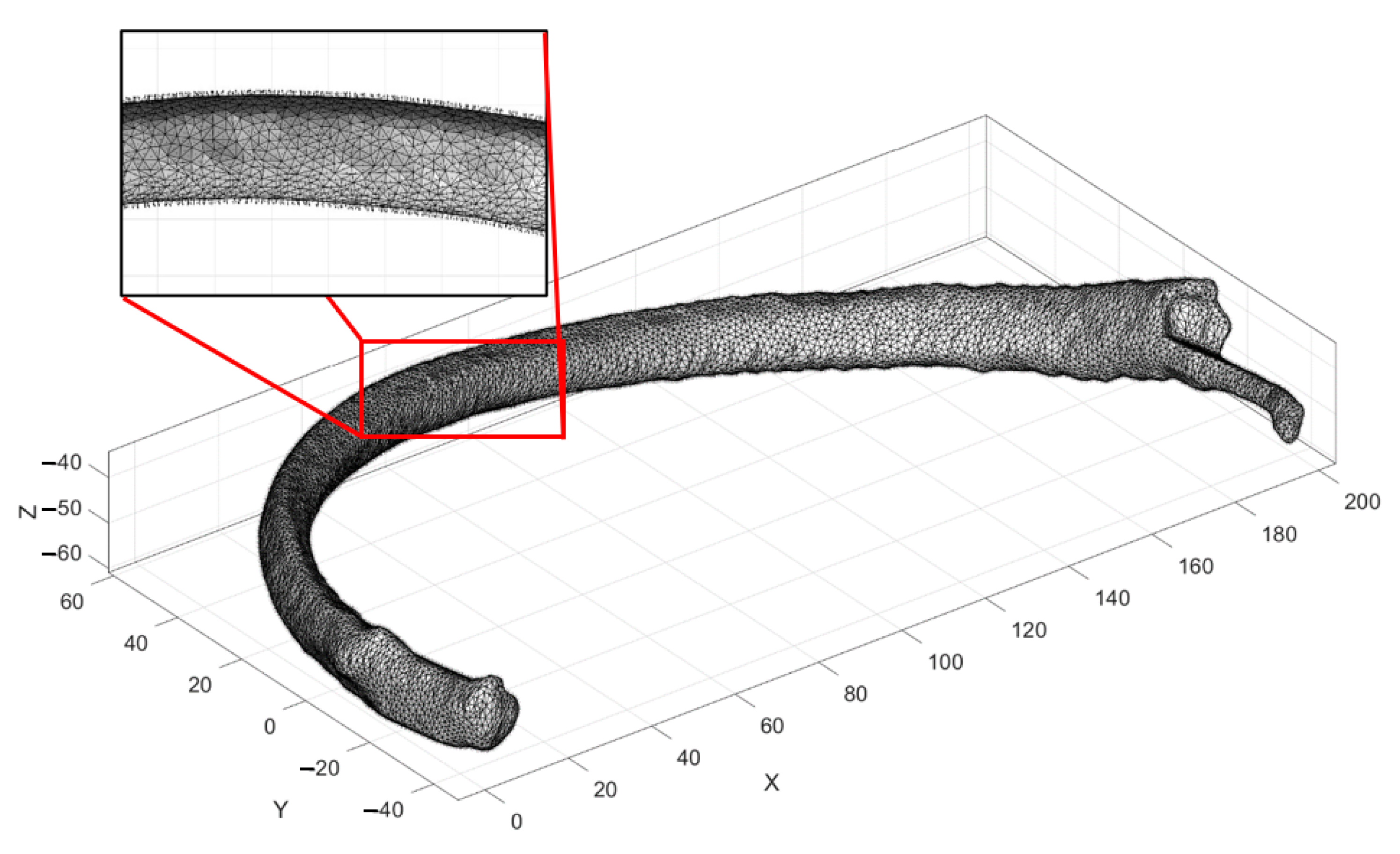
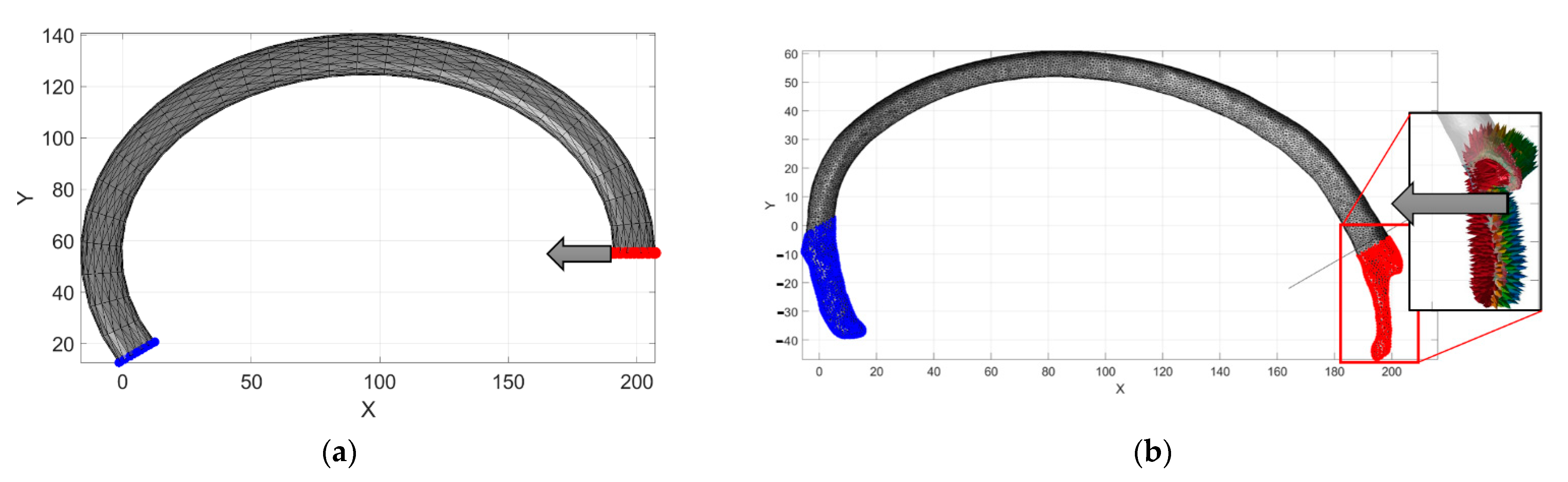
3. Numerical Procedure

The computed geometrical reconstruction’s numerical values are then compared; an FEM model analysis was performed using the data in Table 1 and substituted into Equations (1)–(3). The numerical simulation was run on MATLAB® using an open-source toolbox [23] to compile the analysis. Figure 2 shows the rib’s computed guideline by using Equations (1) and (2).
The computed parametric curve is a guided line on a sweep CAD operation with a controlled tetrahedral mesh. The image used to parametrize the cross-section of the rib reports a voxel size of 0.97 mm. This size could decrease the model’s fidelity by a maximum error of 7%. In this way, an elliptical section was used to approximate the variable shape of the rib. The cross-section of the rib can be described as a ratio of the cortical and cancellous tissues. In [24], this ratio varies from 5% at the tip to 75% in the costovertebral joint. As is mentioned in [12], the rib cross-section was simplified to a solid elliptical shape, and [25] represents a cancellous ratio for the cortical bone of 0.5. In addition, by using Table 2, the model’s material properties can be considered as orthotropic, with a Young’s modulus value of 11.04 GPa, which corresponds to the average value reported. Figure 3 shows a magnified view of the obtained results. First, the ends of the reconstructed sweep CAD operation were computed by using Equation (4). Next, the elements meshed in size and orientations were calculated using the open-source software [26]. The mesh result was obtained under 0.25 s on a laptop with Core i5 8th generation and 16 Gb of ram. The total elements were 1652 tetrahedra and 3802 faces. In this way, we can develop a master curve for the numerical model that can be validated against the tomography model in terms of the solving times and size of the model.
In addition, by using the MATLAB® code, a DICOM® file from the initial dataset was used to build the seventh rib. The right seventh rib has a surface meshed with no control of each element’s orientation, position, or size. Therefore, the STL file has to be reduced from 12.5 MB to 1.51 MB. This reduction was applied because the MATLAB® files for this version v7 were only allowed to work with files with a maximum size of 2 MB. Finally, the tetrahedral mesh was carried out, obtaining a total time of 2.846 s. The total elements obtained were 173,929 tetrahedra and 359,634 faces. The model obtained is shown in Figure 4.
Thus, the simplified reconstructed model was named Model A. This model is shown in Figure 5a. Similarly, Model B represents a virtual model of the reconstructed STL file from the DICOM® tomographic files. This model is shown in Figure 5b. Finally, the results obtained using Equations (5)–(7) are named Model C. The boundary conditions were similar for both geometrical models; the left end of the rib is fixed in all directions, and only a compression force is applied in the “X” direction. On Model A, the left end of the sweep CAD model is fixed in all directions. Therefore, the payload Fq value is applied to the nodes at the right end on Model A. The costovertebral joint is fixed in all directions on Model B. For Model B, the payload Fq value is applied on the nodes near the cartilage section only in the “X” direction. The payload Fq was 180 N; the reported values’ average results are shown in Table 3.
Model A’s computed elapsed time was 0.3 s against Model B, which was 29 min and 28 s. The maximum displacement obtained is shown in Figure 6. First, the nodal distance for Model A ( D d A = 49.20 mm @ 37.57° node ( P A i ( 206 , 55 ) and node P A f ( 167 , 25 ) )) was measured, and the value was compared against the computed results obtained for Model B ( D d B = 53.82 mm @ 54.83° node ( P B i ( 200 , 13 ) and node P B f ( 169 , 57 ) )). The error was around 8.6%. Then, by comparing the same results by using Equation (6) of Model C, the computed results were ( D d C = 48.24 mm P C i (192.8, 56.38),   P C f (166.4, 16.0)). This point has an error of 12.01%. The numerical values shown in Figure 6a represent the reaction points computed through Equation (6). Figure 6b represents the computed values for Model A. Figure 6c represents Model B’s computed values.
Equation (7) of the proposed model estimates the stress–strain that remains upon yielding the bone’s stress value. However, this consideration only applies upon the assumption that the material is orthotropic and lineal, as is shown in Figure 7. It is then verifiable if the existing areas in the STL file model, or the reconstructed rib model, reach the yield stress value reported in Table 2.
The model constructed by the geometrical rib sweep does not present stress values near the yield stress reported in Table 2. In this way, the proposed model is used with certainty to evaluate parameters, such as material conditions (i.e., what if the rib geometry was reconstructed by steel or 3D printed PLA plastic for dummy purposes), the force applied (i.e., how the payload applied affects the displacement of the rib), and, finally, how the modification of the rib inertia values can improve the stiffness of artificial ribs. Thus, 32 simulations were performed in order to evaluate such conditions. The computed results are summarized in Table 3. In addition, we grouped the computed results into six sets of conditions. The first and second sets represent the model’s condition constructed by a geometrical sweep with the main axis of the ellipse in the horizontal and vertical positions, both considering 3D printed PLA plastic. The third and fourth sets of values represent the condition of the model constructed by a geometrical sweep, with the main axis of the ellipse in the horizontal and vertical positions, but this time considering the steel material properties. Finally, the fifth and sixth sets of values represent the computed results of the model constructed by the proposed geometrical sweep, but this time by considering a scaling of two times the original dimensions of the initially measured cross-section of the rib. These considerations were made to evaluate the best way to manufacture the element and also reproduce the biomechanical response.
Figure 8a shows the displacement graphic versus the applied payload. Figure 8b shows the strain–stress curve of the six sets of values. From Figure 8b, we can observe that the model is constructed by a geometrical sweep considering the main axis of the ellipse parallel to the main vertical axis, and the response is closely similar to the biomechanical behavior of the bone. However, in Figure 8a, we can observe that such a response is not similar to the one obtained from the bone material. In contrast, the computed results for the same model use the material properties of 3D printed plastic and consider an increase in the dimensions of the cross-section and the horizontal axis, which is parallel to the main vertical axis and has a similar behavior to the biomechanical response of the payload displacement behavior.

4. Discussion

The model is used to correlate the energy that a rib’s geometry can absorb as a function of its compression, so that it correlates with the material properties of the element and the inertia values related to their cross-section. Even if the proposed model is restricted to the used dataset, the numerical results obtained in this work were consistent in different scenarios and software methods. The model only evaluates the rib’s cross-section as a solid elliptical shape, changing this geometry to modify the porosity’s internal value or the cross-section shape, such as commercial dummies used to compare the results. The model modifies these parameters by changing Equations (2) and (4). The chosen values for the compression limits are described in [3] as the reference parameters to medical conditions, such as fractured ribs, the hemithorax, or pneumothorax. Using the reported values for such criteria was to permanently remain under yielding stress bone material properties to develop a linear stiffness behavior, such as a compressional spring. The rate of compression can be classified as medium-to-light damage. Such a conclusion is as a result of the maximum displacement criteria pointing out a displacement of 52 mm, prior to internal damage or bone fracture [3], and these values can be attributed to the non-breastbone interconnection to other ribs or dynamical conditions. Equations (5) and (6) will be modified to include this interconnection for the entire ribcage in future works. The system’s parameters are modified by changing some anthropometric values to significantly influence the ribcage stiffness. One parameter not analyzed in this paper is vibration, a dangerous factor for the human body. Using the results, it is possible to define the essential anthropometric values that were considered to determine these vibration modes on different systems.

5. Conclusions

This mathematical model uses a dataset to average the geometrical conditions to reconstruct a sweep CAD model and then evaluate the rib’s response under compression caused by a payload of 180 N. The response is characterized as a function of rib stiffness, which is determined by the characteristics of the bone material, rib shape, and the payload value. The numerical results obtained with the proposed formulation establish a straightforward way to understand how the anthropometric values modify ribcage stiffness. These findings suggest an essential role of this parameter on the material used to manufacture artificial dummies. This research has some limitations. The main limitation is the tomographic study. The model’s voxel size does not allow for the evaluation of the cancellous–spongy tissue behavior. In future works, this interaction will be studied. However, given the concern for the small sample, this work highlighted that some dummies’ material properties could represent a serious modifier of real thorax behavior. One way to control this parameter is by manipulating the cross-section, which can increase the ribcage stiffness by almost double, by modifying its shape. Future work will use the mathematical development presented in this paper to evaluate the ribcage stiffness by assuming different material properties and element conditions as a modifier of their response and obtaining a closer biomechanical response to be reproduced in artificial dummies.

Author Contributions

Conceptualization, L.A.A.-P. and C.R.T.-S.; methodology, M.C.; software, L.A.A.-P.; validation, C.R.T.-S., M.C. and G.M.U.-C.; formal analysis, M.C.; investigation, G.M.U.-C.; resources, C.R.T.-S.; data curation, M.C.; writing—original draft preparation, L.A.A.-P.; writing—review and editing, C.R.T.-S.; visualization, G.M.U.-C.; supervision, C.R.T.-S.; project administration, M.C.; funding acquisition, C.R.T.-S. All authors have read and agreed to the published version of the manuscript.

Funding

The authors acknowledge the financial support for realizing this work from the Government of Mexico by the National Council of Science and Technology (CONACYT) and the Instituto Politécnico Nacional. In addition, the authors acknowledge partial support from project 20220646 and the EDI grant, all provided by SIP/IPN.

Institutional Review Board Statement

The Instituto Politécnico Nacional of Mexico does not have an ethics committee to evaluate this research protocol involving human studies. In this case, this research does not fall within the scope of Human Rights. Therefore, there is no legal obligation to evaluate any ethics committee. Additionally, the individual funder and publisher of this project is the Instituto Politécnico Nacional.

Informed Consent Statement

We do not carry out any clinical studies in this research, and we used questionnaires to explain the final uses of tomographic studies in this scientific report.

Data Availability Statement

Not applicable.

Acknowledgments

The authors acknowledge the support for realizing this work from the University of Cassino and the Instituto Politécnico Nacional by the Double Ph.D. program.

Conflicts of Interest

The authors declare no conflict of interest.

References

  1. Agnew, A.; Kang, Y.; Moorhouse, K.; Herriott, R. Age-Related changes in stiffness in human ribs. In Proceedings of the International Research Council on Biomechanics of Injury Conference, Gothenburg, Sweden, 11–13 September 2013. [Google Scholar]
  2. Augenstein, J.; Perdeck, E.; Martin, P.; Bowen, J.; Stratton, J.; Horton, T.; Singer, M.; Digges, K.; Steps, J. Injuries to restrained occupants in far-side crashes. In Proceedings of the Annual Meetings/Association for the Advancement of Automotive Medicine, Chicago, IL, USA, 2–4 October 2000. [Google Scholar]
  3. Schmitt, K.; Niederer, P.; Muser, M.; Walz, F. Trauma Biomechanics: Accidental Injury in Traffic and Sports, Zurich, Switzerland; Springer: Berlin/Heidelberg, Germany, 2007. [Google Scholar]
  4. Baudrit, P.; Leport, T. Rib strain fields corridors inside and oblique impact based on PMHS tests. In Proceedings of the Thirty-Eight International Workshop, Scottsdale, AZ, USA, 24–29 October 2010. [Google Scholar]
  5. Cavanaugh, J.; Jepsen, K.; King, A. Quasi-static frontal loading of the thorax of human cadavers and the Hybrid III dummy. In Proceedings of the 16th Annual International Workshop on Human Subjects for Biomechanical Research, Atlanta, GA, USA, 16 October 1988. [Google Scholar]
  6. Duma, S.; Kemper, A.; Stitzel, J.; McNally, C.; Kennedy, E.; Matsuoka, F. Rib fracture timing in dynamic belt tests with human cadavers. Clin. Anat. 2011, 24, 327–338. [Google Scholar] [CrossRef]
  7. Perz, R.; Toczyski, J.; Kindig, M.; Ito, D.; Ejima, S.; Yasuki, T.; Crandall, J. Evaluation of the geometrical properties distribution along the human ribs using different x-ray imaging methods. In Proceedings of the International Research Council on Biomechanics of Injury Conference, Gothenburg, Sweden, 11–13 September 2013. [Google Scholar]
  8. Holcombe, S.; Ejima, S.; Huhdanpaa, H.; Jones, A.; Wang, S. Ribcage characterization for FE using automatic CT processing. In Proceedings of the 5th IEEE International Symposium on Biomedical Imaging: From Nano to Macro, Paris, France, 14–17 May 2008. [Google Scholar]
  9. Mohr, M.; Engel, C.; Bottlang, M.; Abrams, E. Cross-sectional geometry of human ribs. Cortex 2003, 80, 2–10. [Google Scholar]
  10. Aguilar-Perez, L.; Torres-San-Miguel, C.; Ceccarelli, M. Design of a methodology for the determination of the mechanical rib stiffness as injury index. In New Trends in Medical and Service Robotics; Rauter, G., Cattin, P.C., Zam, A., Riener, R., Carbone, G., Pisla, D., Eds.; Springer: Berlin/Heidelberg, Germany, 2019; pp. 62–69. [Google Scholar]
  11. Boresi, A.; Schmidt, R. Advanced Mechanics of Materials, 6th ed.; John Wiley & Sons: Hoboken, NJ, USA, 2004. [Google Scholar]
  12. Devon, A.; Kang, Y.; Agnew, A.; Kemper, A. The effect of injurious whole rib loading on ribcortical bone material properties. In Proceedings of the International Research Council on the Biomechanics of Injury Conference, Athens, Greece, 12–14 September 2018. [Google Scholar]
  13. Yoganandan, N.; Pintar, F. Biomechanics of human thoracic ribs. J. Biomech. Eng. 1998, 120, 100–104. [Google Scholar] [CrossRef] [PubMed]
  14. Roth, S.; Torres, F.; Feuerstein, P.; Thoral-Pierre, K. Anthropometric dependence of the response of a thorax FE model under high speed loading: Validation and real world accident replication. Comput. Methods Programs Biomed. 2013, 110, 160–170. [Google Scholar] [CrossRef]
  15. Currey, J. The structure and mechanics of bone. J. Mater. Sci. 2012, 47, 41–54. [Google Scholar] [CrossRef]
  16. Kieser, J.; Weller, S.; Swain, M.; Neil, W.; Das, R. Compressive rib fracture: Peri-mortem and post-mortem trauma patterns in a pig model. Leg. Med. 2013, 15, 193–201. [Google Scholar] [CrossRef] [PubMed]
  17. Pezowics, C.; Glowacki, M. The mechanical properties of human ribs in young adult. Acta Bioeng. Biomech. 2012, 14, 53–60. [Google Scholar]
  18. Gilchrist, M. IUTAM Symposium on Impact Biomechanics: From Fundamental Insights to Applications; Springer: Dublin, Ireland, 2005. [Google Scholar]
  19. Forbes, A. Development of a Human Body Model for the Analysis of Side Impact. Master’s Thesis, Department of Mechanical Engineering, Waterloo, ON, Canada, 2005. [Google Scholar]
  20. Stein, I.; Granik, G. Rib structure and bending strength: An autopsy study. Calcif. Tissue Res. 1976, 20, 61–73. [Google Scholar] [CrossRef] [PubMed]
  21. Abellán, D.; Sánchez, M.; Martínez, L. Frontal crashworthiness characterization of a vehicle segment using curve comparison metrics. Accid. Anal. Prev. 2018, 117, 136–144. [Google Scholar] [CrossRef] [PubMed]
  22. Awoukeng, G.; Thoral, K.; Roth, S. Biomechanical model of the thorax under blast loading: A three-dimensional numerical study. Int. J. Numer. Methods Biomed. Eng. 2014, 12, 1667–1678. [Google Scholar]
  23. Moerman, K. GIBBON: The geometry and image-based bioengineering add-on. J. Open-Source Softw. 2018, 3, 506. [Google Scholar] [CrossRef]
  24. Mohr, M.; Abrams, E.; Engel, C.; Long, W.; Bottlang, M. Geometry of humans ribs pertinent to orthopedic chest wall reconstruction. J. Biomech. 2007, 40, 1310–1317. [Google Scholar] [CrossRef] [PubMed]
  25. Roberts, S.; Chen, P. Global geometric characteristics of typical human ribs. J. Biomech. 1972, 5, 191–201. [Google Scholar] [CrossRef]
  26. Si, H. TetGen, a delaunay-Based quality tetrahedral mesh generator. ACM Trans. Math. Softw. 2015, 41, 1–36. [Google Scholar] [CrossRef]
Figure 1. Parametric curve of the rib: (a) horizontal plane view; (b) sagittal plane view.
Ijerph 19 03414 g001
Figure 2. Comparative computed guided line values of the rib’s reconstruction against the dataset used.
Ijerph 19 03414 g002
Figure 3. Local controlled mesh computed with a guided line of the rib reconstruction.
Ijerph 19 03414 g003
Figure 4. The model of the biomechanical tomographic images.
Ijerph 19 03414 g004
Figure 5. Biomechanical boundary conditions: (a) proposed reconstructed model; (b) STL rib model.
Ijerph 19 03414 g005
Figure 6. The biomechanical model’s boundary conditions: (a) own developed model; (b) geometrical rib reconstruction; (c) STL model of the rib.
Ijerph 19 03414 g006
Figure 7. The biomechanical model’s stress distribution: (a) geometrical rib reconstruction; (b) STL model of the rib.
Ijerph 19 03414 g007
Figure 8. Comparative analysis of the computed results. (a) displacement versus payload; (b) strain versus stress.
Ijerph 19 03414 g008
Table 1. Morphological parameters from 4 tomographic studies.
Dataset 1Dataset 2Dataset 3Dataset 4
Age75214322
GenreMMFM
Voxel size
Z (mm)1.5241
X (mm)0.680.970.680.97
Y (mm)0.680.970.680.97
Wide side (W, mm)96.0410693.599
Short side (H, mm)63.0073.574.573
The Radius of the Cross-Section
Z1 (mm)16.2220.701917.7
Z2 (mm)11.0212.807.348.56
Y1 (mm)10.4811.5010.511.6
Y2 (mm)4.884.402.513.79
Table 2. Values reported for orthotropic material bone properties.
AuthorMaximum Payload Application Reported before BreakingYoung’s Module
(E, GPa)
Velocity
(mm/min)
σu
(MPa)
Yoganandan [13] 1532.372.502.102
Roth [14]---14.00---70.00
Currey [15]---13.00---110.00
Kieser [16]1504.7010.0053.33
Pezowics [17]---5.97------
Gilchrist [18]---11.50------
Forbes [19]---26.00------
Stein y Granik [20]226.8011.502.54106.00
Martínez-Sáez [21]---7.501.70---
Goumtcha [22] ---14.00---70.00
Table 3. Computed values for the model constructed by a geometrical rib sweep.
Payload
(N)
δx
(mm)
Ut
(J)
k
The main vertical axis of the rib cross-sectionBONE151.52660.21490.1844
303.05320.8597
454.57971.9343
909.15957.7372
18018.31930.949
20020.354438.2086
22022.389946.2324
24024.425355.0204
PLASTIC157.38660.83210.0305
3014.77323.3284
4522.15987.4889
9044.319529.9554
18088.6391119.8217
20098.4879147.928
220108.3366178.9929
240118.1854213.0164
STEEL150.12940.01571.8734
300.25880.0628
450.38820.1412
900.77650.5648
1801.5532.2591
2001.72552.789
2201.89813.3747
2402.07064.0162
PLASTIC
2 × the cross-section
150.46410.08460.786
300.92820.3386
451.39230.7618
902.78473.0473
1805.569312.1892
2006.188215.0484
2206.80718.2086
2407.425821.6697
Horizontal main axis of the cross rib sectionPLASTIC151.591715.98550.0125
306.366731.9709
4514.32547.9564
9057.395.9128
180229.1999191.8256
200282.9628213.1396
220342.385234.4535
240407.4664255.7675
STEEL150.0290.27990.7399
300.11590.5598
450.26080.8397
901.04331.6794
1804.17323.3588
2005.15213.7319
2206.23414.1051
2407.4194.4783
PLASTIC
2 × the cross-section
150.13211.00150.2634
300.52852.0031
451.18913.0046
904.75636.0093
18019.025412.0185
20023.488113.3539
22028.420614.6893
24033.822916.0247
Publisher’s Note: MDPI stays neutral with regard to jurisdictional claims in published maps and institutional affiliations.

