In Silico Analysis of the Subtype Selective Blockage of KCNA Ion Channels through the µ-Conotoxins PIIIA, SIIIA, and GIIIA


Abstract
1. Introduction
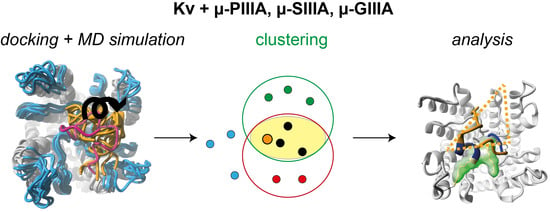
2. Methods
2.1. Homology Modelling
2.2. Docking
2.3. Molecular Dynamics Simulations and Energy Minimizations
3. Results and Discussion
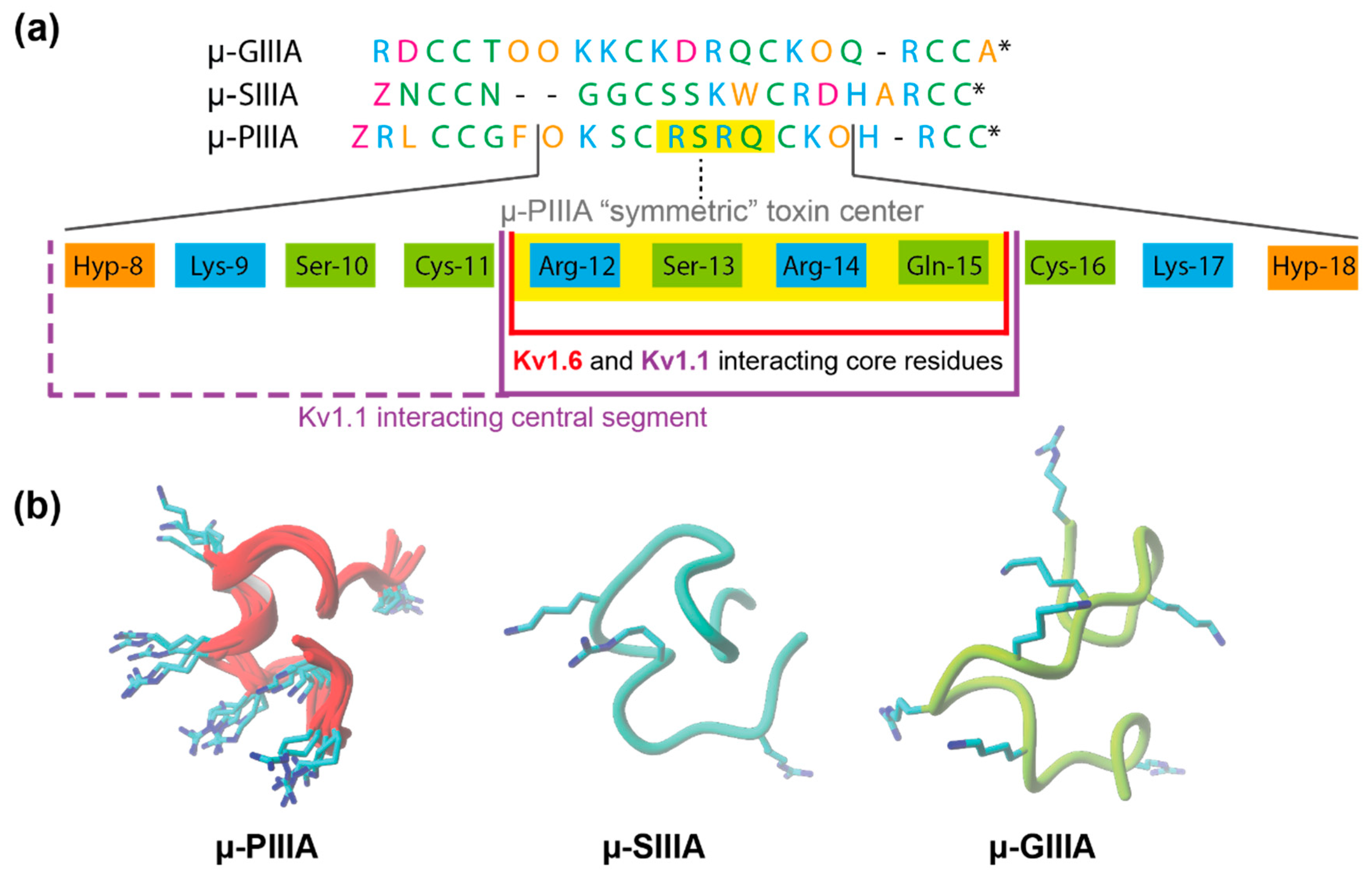
3.1. Toxin Dynamics and Cluster Analysis
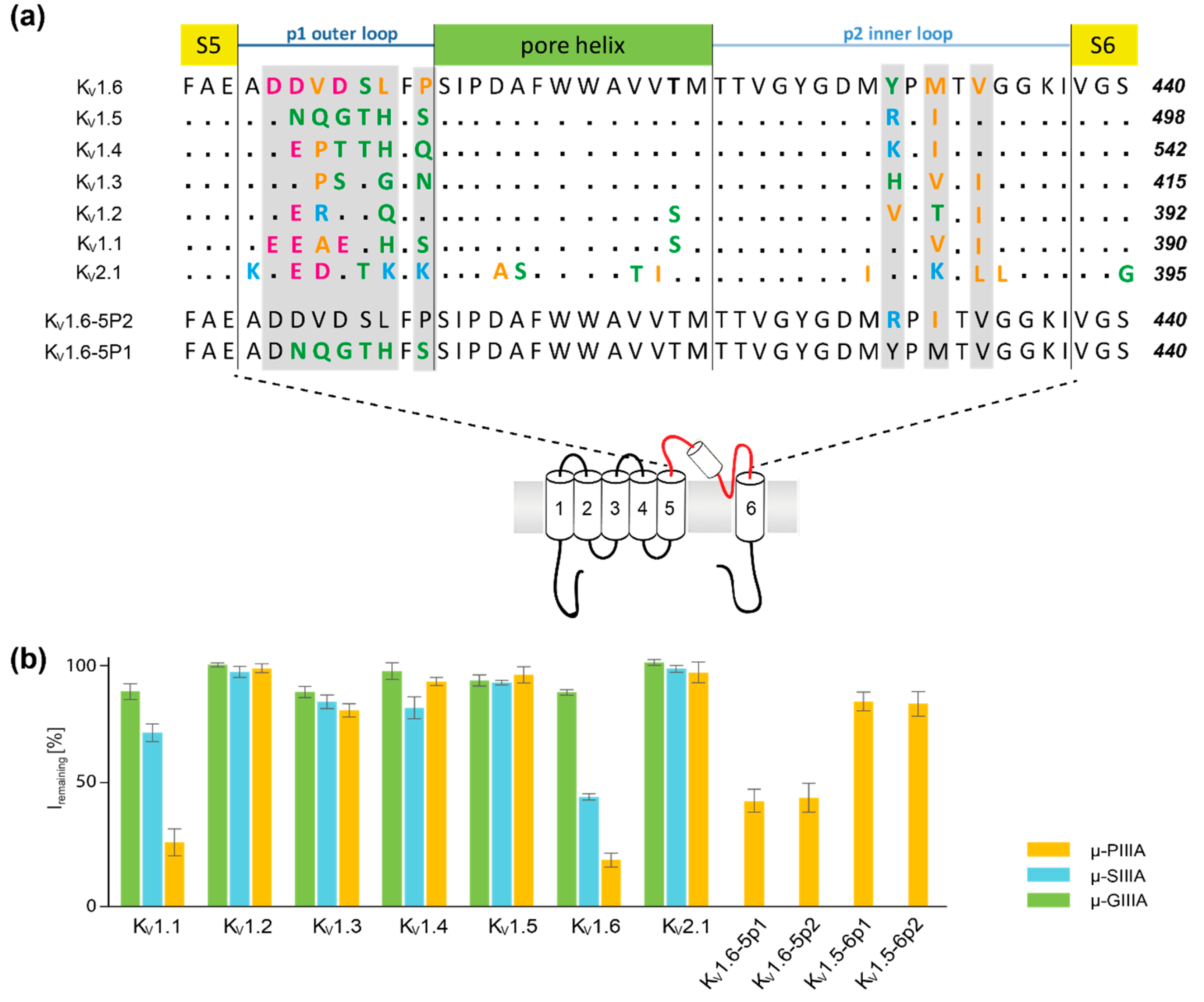
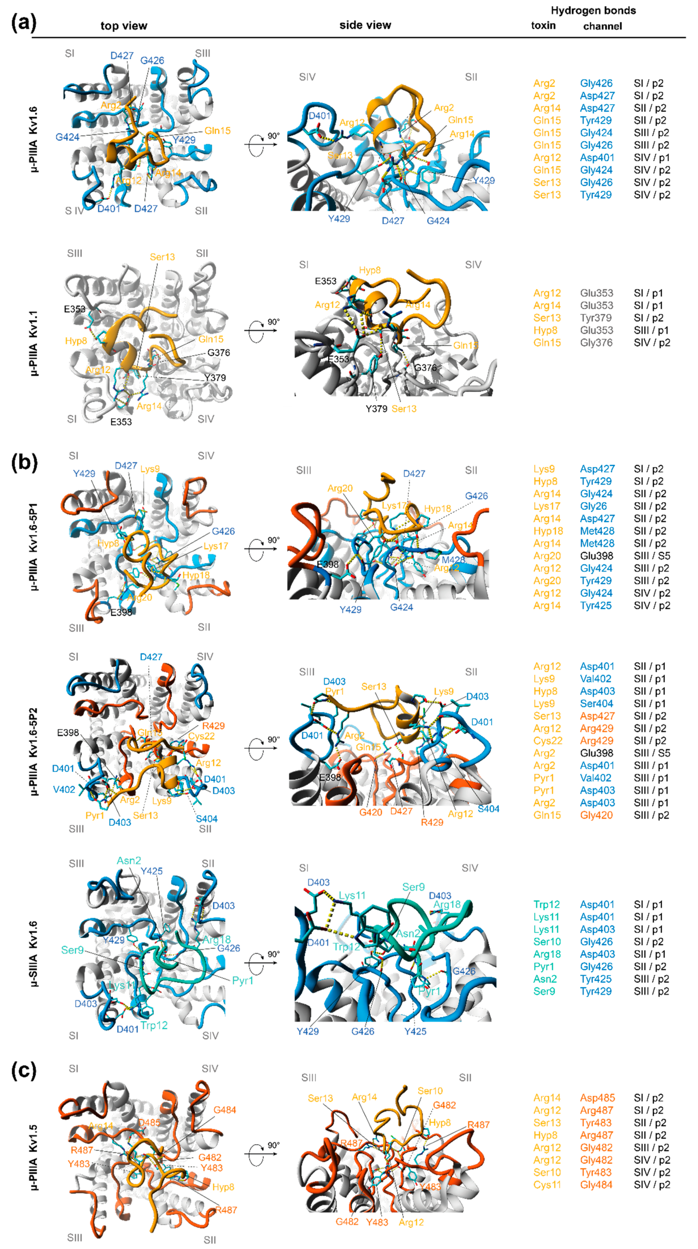
3.2. Analysis of Channel-Toxin Interactions
4. Conclusions
Supplementary Materials
Author Contributions
Funding
Conflicts of Interest
References
- Leipold, E.; Ullrich, F.; Thiele, M.; Tietze, A.A.; Terlau, H.; Imhof, D.; Heinemann, S.H. Subtype-specific block of voltage-gated K+ channels by mu-conopeptides. Biochem. Biophys. Res. Commun. 2017, 482, 1135–1140. [Google Scholar] [CrossRef] [PubMed]
- Doyle, D.A.; Morais Cabral, J.; Pfuetzner, R.A.; Kuo, A.; Gulbis, J.M.; Cohen, S.L.; Chait, B.T.; MacKinnon, R. The structure of the potassium channel: Molecular basis of K+ conduction and selectivity. Science 1998, 280, 69–77. [Google Scholar] [CrossRef] [PubMed]
- Marban, E.; Yamagishi, T.; Tomaselli, G.F. Structure and function of voltage-gated sodium channels. J. Physiol. 1998, 508 Pt 3, 647–657. [Google Scholar] [CrossRef]
- Jensen, M.O.; Jogini, V.; Borhani, D.W.; Leffler, A.E.; Dror, R.O.; Shaw, D.E. Mechanism of Voltage Gating in Potassium Channels. Science 2012, 336, 229–233. [Google Scholar] [CrossRef] [PubMed]
- Groome, J.R.; Winston, V. S1-S3 counter charges in the voltage sensor module of a mammalian sodium channel regulate fast inactivation. J. Gen. Physiol. 2013, 141, 601–618. [Google Scholar] [CrossRef] [PubMed]
- Groome, J.R.; Winston, V. Correction: S1-S3 counter charges in the voltage sensor module of a mammalian sodium channel regulate fast inactivation. J. Gen. Physiol. 2015, 146, 541–546. [Google Scholar] [CrossRef]
- Long, S.B.; Tao, X.; Campbell, E.B.; MacKinnon, R. Atomic structure of a voltage-dependent K+ channel in a lipid membrane-like environment. Nature 2007, 450, 376–382. [Google Scholar] [CrossRef] [PubMed]
- Pan, X.; Li, Z.; Zhou, Q.; Shen, H.; Wu, K.; Huang, X.; Chen, J.; Zhang, J.; Zhu, X.; Lei, J.; et al. Structure of the human voltage-gated sodium channel Nav1.4 in complex with β1. Science 2018, 362, eaau2486. [Google Scholar] [CrossRef]
- Shen, H.; Zhou, Q.; Pan, X.; Li, Z.; Wu, J.; Yan, N. Structure of a eukaryotic voltage-gated sodium channel at near-atomic resolution. Science 2017, 355. [Google Scholar] [CrossRef]
- Shen, H.; Liu, D.; Wu, K.; Lei, J.; Yan, N. Structures of human Nav1.7 channel in complex with auxiliary subunits and animal toxins. Science 2019. [Google Scholar] [CrossRef]
- Pan, X.; Li, Z.; Huang, X.; Huang, G.; Gao, S.; Shen, H.; Liu, L.; Lei, J.; Yan, N. Molecular basis for pore blockade of human Na+ channel Nav1.2 by the μ-conotoxin KIIIA. Science 2019. [Google Scholar] [CrossRef] [PubMed]
- Clairfeuille, T.; Cloake, A.; Infield, D.T.; Llongueras, J.P.; Arthur, C.P.; Li, Z.R.; Jian, Y.; Martin-Eauclaire, M.-F.; Bougis, P.E.; Ciferri, C.; et al. Structural basis of α-scorpion toxin action on Nav channels. Science 2019. [Google Scholar] [CrossRef] [PubMed]
- Shen, H.; Li, Z.; Jiang, Y.; Pan, X.; Wu, J.; Cristofori-Armstrong, B.; Smith, J.J.; Chin, Y.K.Y.; Lei, J.; Zhou, Q.; et al. Structural basis for the modulation of voltage-gated sodium channels by animal toxins. Science 2018, 362. [Google Scholar] [CrossRef]
- Salgado, V.L.; Yeh, J.Z.; Narahashi, T. Use- and voltage-dependent block of the sodium channel by saxitoxin. Ann. N. Y. Acad. Sci. 1986, 479, 84–95. [Google Scholar] [CrossRef] [PubMed]
- Rundfeldt, C. The new anticonvulsant retigabine (D-23129) acts as an opener of K+ channels in neuronal cells. Eur. J. Pharmacol. 1997, 336, 243–249. [Google Scholar] [CrossRef]
- Main, M.J.; Cryan, J.E.; Dupere, J.R.; Cox, B.; Clare, J.J.; Burbidge, S.A. Modulation of KCNQ2/3 potassium channels by the novel anticonvulsant retigabine. Mol. Pharmacol. 2000, 58, 253–262. [Google Scholar] [CrossRef]
- Cox, J.J.; Reimann, F.; Nicholas, A.K.; Thornton, G.; Roberts, E.; Springell, K.; Karbani, G.; Jafri, H.; Mannan, J.; Raashid, Y.; et al. An SCN9A channelopathy causes congenital inability to experience pain. Nature 2006, 444, 894–898. [Google Scholar] [CrossRef] [PubMed]
- McArthur, J.R.; Singh, G.; O’Mara, M.L.; McMaster, D.; Ostroumov, V.; Tieleman, D.P.; French, R.J. Orientation of mu-conotoxin PIIIA in a sodium channel vestibule, based on voltage dependence of its binding. Mol. Pharmacol. 2011, 80, 219–227. [Google Scholar] [CrossRef] [PubMed]
- McArthur, J.R.; Ostroumov, V.; Al-Sabi, A.; McMaster, D.; French, R.J. Multiple, distributed interactions of mu-conotoxin PIIIA associated with broad targeting among voltage-gated sodium channels. Biochemistry 2011, 50, 116–124. [Google Scholar] [CrossRef]
- Al-Sabi, A.; McArthur, J.; Ostroumov, V.; French, R.J. Marine toxins that target voltage-gated sodium channels. Mar. Drugs 2006, 4, 157–192. [Google Scholar] [CrossRef]
- Terlau, H.; Olivera, B.M. Conus venoms: A rich source of novel ion channel-targeted peptides. Physiol. Rev. 2004, 84, 41–68. [Google Scholar] [CrossRef]
- Jacob, R.B.; McDougal, O.M. The M-superfamily of conotoxins: A review. Cell. Mol. Life Sci. 2010, 67, 17–27. [Google Scholar] [CrossRef]
- Norton, R.S. Mu-conotoxins as leads in the development of new analgesics. Molecules 2010, 15, 2825–2844. [Google Scholar] [CrossRef]
- Khoo, K.K.; Feng, Z.P.; Smith, B.J.; Zhang, M.M.; Yoshikami, D.; Olivera, B.M.; Bulaj, G.; Norton, R.S. Structure of the analgesic mu-conotoxin KIIIA and effects on the structure and function of disulfide deletion. Biochemistry 2009, 48, 1210–1219. [Google Scholar] [CrossRef]
- Leipold, E.; Markgraf, R.; Miloslavina, A.; Kijas, M.; Schirmeyer, J.; Imhof, D.; Heinemann, S.H. Molecular determinants for the subtype specificity of mu-conotoxin SIIIA targeting neuronal voltage-gated sodium channels. Neuropharmacology 2011, 61, 105–111. [Google Scholar] [CrossRef]
- Yao, S.; Zhang, M.M.; Yoshikami, D.; Azam, L.; Olivera, B.M.; Bulaj, G.; Norton, R.S. Structure, dynamics, and selectivity of the sodium channel blocker mu-conotoxin SIIIA. Biochemistry 2008, 47, 10940–10949. [Google Scholar] [CrossRef]
- Bulaj, G.; West, P.J.; Garrett, J.E.; Marsh, M.; Zhang, M.M.; Norton, R.S.; Smith, B.J.; Yoshikami, D.; Olivera, B.M. Novel conotoxins from Conus striatus and Conus kinoshitai selectively block TTX-resistant sodium channels. Biochemistry 2005, 44, 7259–7265. [Google Scholar] [CrossRef]
- Chen, F.; Huang, W.; Jiang, T.; Yu, R. Determination of the mu-Conotoxin PIIIA Specificity Against Voltage-Gated Sodium Channels from Binding Energy Calculations. Mar. Drugs 2018, 16, 153. [Google Scholar] [CrossRef]
- Chen, R.; Robinson, A.; Chung, S.-H. Mechanism of μ-Conotoxin PIIIA Binding to the Voltage-Gated Na+ Channel NaV1.4. PLoS ONE 2014, 9, e93267. [Google Scholar] [CrossRef]
- Krieger, E.; Vriend, G. YASARA View—Molecular graphics for all devices—From smartphones to workstations. Bioinformatics 2014, 30, 2981–2982. [Google Scholar] [CrossRef]
- Krieger, E.; Joo, K.; Lee, J.; Lee, J.; Raman, S.; Thompson, J.; Tyka, M.; Baker, D.; Karplus, K. Improving physical realism, stereochemistry, and side-chain accuracy in homology modeling: Four approaches that performed well in CASP8. Proteins Struct. Funct. Bioinf. 2009, 77, 114–122. [Google Scholar] [CrossRef]
- Altschul, S.F.; Madden, T.L.; Schaffer, A.A.; Zhang, J.; Zhang, Z.; Miller, W.; Lipman, D.J. Gapped BLAST and PSI-BLAST: A new generation of protein database search programs. Nucleic Acids Res. 1997, 25, 3389–3402. [Google Scholar] [CrossRef]
- Suzek, B.E.; Wang, Y.; Huang, H.; McGarvey, P.B.; Wu, C.H.; UniProt, C. UniRef clusters: A comprehensive and scalable alternative for improving sequence similarity searches. Bioinformatics 2015, 31, 926–932. [Google Scholar] [CrossRef]
- Jones, D.T. Protein secondary structure prediction based on position-specific scoring matrices. J. Mol. Biol. 1999, 292, 195–202. [Google Scholar] [CrossRef]
- Canutescu, A.A.; Shelenkov, A.A.; Dunbrack Jr, R.L. A graph theory algorithm for rapid protein side chain prediction. Protein Sci. 2003, 12, 2001–2014. [Google Scholar] [CrossRef]
- Krieger, E.; Dunbrack, R.L., Jr.; Hooft, R.W.; Krieger, B. Assignment of protonation states in proteins and ligands: Combining pKa prediction with hydrogen bonding network optimization. Methods Mol. Biol. 2012, 819, 405–421. [Google Scholar] [CrossRef]
- Tietze, A.A.; Tietze, D.; Ohlenschlager, O.; Leipold, E.; Ullrich, F.; Kuhl, T.; Mischo, A.; Buntkowsky, G.; Gorlach, M.; Heinemann, S.H.; et al. Structurally diverse mu-conotoxin PIIIA isomers block sodium channel NaV 1.4. Angew. Chem. Int. Ed. Engl. 2012, 51, 4058–4061. [Google Scholar] [CrossRef]
- Dominguez, C.; Boelens, R.; Bonvin, A.M. HADDOCK: A protein-protein docking approach based on biochemical or biophysical information. J. Am. Chem. Soc. 2003, 125, 1731–1737. [Google Scholar] [CrossRef]
- Van Zundert, G.C.P.; Rodrigues, J.; Trellet, M.; Schmitz, C.; Kastritis, P.L.; Karaca, E.; Melquiond, A.S.J.; van Dijk, M.; de Vries, S.J.; Bonvin, A. The HADDOCK2.2 Web Server: User-Friendly Integrative Modeling of Biomolecular Complexes. J. Mol. Biol. 2016, 428, 720–725. [Google Scholar] [CrossRef]
- De Vries, S.J.; van Dijk, M.; Bonvin, A.M. The HADDOCK web server for data-driven biomolecular docking. Nat. Protoc. 2010, 5, 883–897. [Google Scholar] [CrossRef]
- Trott, O.; Olson, A.J. Software News and Update AutoDock Vina: Improving the Speed and Accuracy of Docking with a New Scoring Function, Efficient Optimization, and Multithreading. J. Comput. Chem. 2010, 31, 455–461. [Google Scholar] [CrossRef] [PubMed]
- Krieger, E.; Vriend, G. New ways to boost molecular dynamics simulations. J. Comput. Chem. 2015, 36, 996–1007. [Google Scholar] [CrossRef] [PubMed]
- Essmann, U.; Perera, L.; Berkowitz, M.L.; Darden, T.; Lee, H.; Pedersen, L.G. A smooth particle mesh Ewald method. J. Chem. Phys. 1995, 103, 8577–8593. [Google Scholar] [CrossRef]
- Krieger, E.; Nielsen, J.E.; Spronk, C.A.; Vriend, G. Fast empirical pKa prediction by Ewald summation. J. Mol. Graph. Model. 2006, 25, 481–486. [Google Scholar] [CrossRef] [PubMed]
- Maier, J.A.; Martinez, C.; Kasavajhala, K.; Wickstrom, L.; Hauser, K.E.; Simmerling, C. ff14SB: Improving the Accuracy of Protein Side Chain and Backbone Parameters from ff99SB. J. Chem. Theory Comput. 2015, 11, 3696–3713. [Google Scholar] [CrossRef] [PubMed]
- Hornak, V.; Abel, R.; Okur, A.; Strockbine, B.; Roitberg, A.; Simmerling, C. Comparison of multiple Amber force fields and development of improved protein backbone parameters. Proteins 2006, 65, 712–725. [Google Scholar] [CrossRef] [PubMed]
- Hess, B.; Bekker, H.; Berendsen, H.J.C.; Fraaije, J.G.E.M. LINCS: A linear constraint solver for molecular simulations. J. Comput. Chem. 1997, 18, 1463–1472. [Google Scholar] [CrossRef]
- Miyamoto, S.; Kollman, P.A. Settle: An analytical version of the SHAKE and RATTLE algorithm for rigid water models. J. Comput. Chem. 1992, 13, 952–962. [Google Scholar] [CrossRef]


| HADDOCK Z-Score | HADDOCK Score | Vina Score (kcal/mol) | ||
|---|---|---|---|---|
| μ-PIIIA Kv1.6 | active | −1.0 | 174.3 ± 8.7 | 10.5 |
| μ-PIIIA Kv1.1 | active | −1.4 | 202.1 ± 5.9 | 9.5 |
| μ-PIIIA Kv1.6-5P1 | semi-active | −1.4 | 178.2 ± 14.0 | 9.7 |
| μ-PIIIA Kv1.6-5P2 | semi-active | −0.9 | 196.0 ± 12.7 | 10.0 |
| μ-SIIIA Kv1.6 | semi-active | −1.3 | 231.1 ± 14.7 | 10.2 |
| μ-PIIIA Kv1.5 | inactive | −1.6 | 202.6 ± 10.5 | 8.5 |
| μ-GIIIA Kv1.6 | inactive | −1.7 | 187.1 ± 14.0 | 8.0 |
© 2019 by the authors. Licensee MDPI, Basel, Switzerland. This article is an open access article distributed under the terms and conditions of the Creative Commons Attribution (CC BY) license (http://creativecommons.org/licenses/by/4.0/).
Share and Cite
Kaufmann, D.; Tietze, A.A.; Tietze, D. In Silico Analysis of the Subtype Selective Blockage of KCNA Ion Channels through the µ-Conotoxins PIIIA, SIIIA, and GIIIA. Mar. Drugs 2019, 17, 180. https://doi.org/10.3390/md17030180
Kaufmann D, Tietze AA, Tietze D. In Silico Analysis of the Subtype Selective Blockage of KCNA Ion Channels through the µ-Conotoxins PIIIA, SIIIA, and GIIIA. Marine Drugs. 2019; 17(3):180. https://doi.org/10.3390/md17030180
Chicago/Turabian StyleKaufmann, Desirée, Alesia A. Tietze, and Daniel Tietze. 2019. "In Silico Analysis of the Subtype Selective Blockage of KCNA Ion Channels through the µ-Conotoxins PIIIA, SIIIA, and GIIIA" Marine Drugs 17, no. 3: 180. https://doi.org/10.3390/md17030180
APA StyleKaufmann, D., Tietze, A. A., & Tietze, D. (2019). In Silico Analysis of the Subtype Selective Blockage of KCNA Ion Channels through the µ-Conotoxins PIIIA, SIIIA, and GIIIA. Marine Drugs, 17(3), 180. https://doi.org/10.3390/md17030180