
Enhanced Strength and Electrical Conductivity in Graphite-Cement Mortars with Carbonized Titanium-Bearing Blast Furnace Slag as an Aggregate

1
Key Laboratory of Metallurgical Emission Reduction & Resources Recycling, Anhui University of Technology, Ministry of Education, Ma’anshan 243002, China
2
Anhui Province Key Laboratory of Metallurgical Engineering & Resources Recycling, Anhui University of Technology, Ma’anshan 243002, China
3
School of Materials Science and Engineering, Anhui University of Technology, Ma’anshan 243002, China
*
Author to whom correspondence should be addressed.
Metals 2022, 12(5), 754; https://doi.org/10.3390/met12050754
Submission received: 22 March 2022
/
Revised: 21 April 2022
/
Accepted: 26 April 2022
/
Published: 28 April 2022
(This article belongs to the Special Issue Comprehensive Utilization of Metallurgical Slag Resources)
Abstract
:Titanium-containing carbide slag (TCS) is the product obtained by high-temperature carbothermal reduction in Titanium-bearing blast furnace slag (TBFS), which contains a large amount of TiC phase with excellent electrical conductivity. In this paper, conductive cement mortar was prepared with TCS as an aggregate and graphite as a conductive phase. The content of graphite on the compressive strength and electrical resistivity of the prepared cement mortar was investigated. The results showed that the replacement of standard sand with TCS as an aggregate not only significantly reduced the electrical resistivity of the cement mortar, but also improved its compressive strength. When the graphite content was 10 wt%, the cement mortar with TCS as the aggregate exhibited excellent comprehensive performance with the 28d compressive strength of 34.0 MPa and the electrical resistivity of 2.9 Ω m in dry condition, respectively. The results of this paper provided a new way both for the utilization of TBFS and the preparation of conductive cement mortars.
1. Introduction
Ti-bearing blast furnace slag (TBFS) is produced in an ironmaking process from vanadium-titanium magnetite ore and its production is up to 3 million tons per year. Due to its high content of TiO2 (20–25%), TBFS has been extensively studied as an important titanium resource [1]. At present, extracting TiO2 and preparing titanium-containing compounds are the main routes to exploit TBFS [2,3,4,5,6,7,8,9]. For example, extracting titanium from TBFS by the high-temperature carbonization and low-temperature chlorination process is being pilot tested in Panzhihua, China. In this process, TBFS is first carbonized above 1600 °C to form carbonized slag in which TiO2 is converted into TiC, and then chlorinated by Cl2 at around 500 °C to produce TiCl4 [3]. Recently, TBFS and diamond wire saw silicon kerf (DWSSK) were treated together and produced TiO2 and high-purity Si simultaneously [2]. Firstly, DWSSK (86.9% Si) was employed as a reductant to extract Ti from TBFS to prepare bulk Si-Ti alloys. Secondly, Si and Ti in the bulk Si-Ti alloy were separated using a HF-containing acid solution. Ti in the Si-Ti alloy dissolved into the HF-containing acid solution, and high-purity Si (99.94%) was obtained after acid leaching. Although the existing methods to utilize TBFS are able to extract or exploit Ti, they are either process-complex or costly. Additionally, more importantly, only titanium element is considered for use and the production of solid waste is inevitable, causing secondary environmental pollution. Therefore, it is urgent to develop new technologies to utilize TBFS with large scale, full component, and high added value.
Cement-based composites, including pastes, mortars and concrete, have been widely used in civil engineering due to their excellent physical properties and low cost. Normally, cement-based composites act as structural parts to defend various damages such as deformation and fracture, and their service time generally lasts for dozens or even hundreds of years. As a result, repair and maintenance are necessary for cement-based composites. However, traditionally, the inspection of cement-based composites is carried out by visual observation, which is laborious and sometimes dangerous. Although the use of monitoring systems can solve the above issues, visual inspection is highly subjective, and the real problem is not necessarily able to be discovered. Considering that both deformation and fracture change the electrical resistivity of conductive materials, self-inspection is possible for cement-based composites if they are electrically conductive [10]. Moreover, electrically conductive cement-based composites can serve as structural-functional integrated materials and be used in a deicing or snow melting system [11], antistatic flooring, building heating units and electromagnetic shielding [12,13].
As is known to all, the electrical resistivity of traditional cement is generally in the range of 103–106 Ω m, which is insufficient for use as a conductive material. The addition of electrically conductive fillers into traditional cement to form a conductive network has been proven to greatly improve the electrical conductivity of the composites. The most commonly used conductive fillers include steel fiber, graphite powder and carbon fiber [14]. Due to its excellent machinability, high strength and good conductivity, steel fiber is preferred as a conductive filler to prepare conductive cement-based composites. Experiments have demonstrated that the incorporation of steel fiber greatly enhanced the tensile, bending and shear strength, as well as the electrical conductivity of the cement-based composite. However, the electrical resistivity of the cement-based composite increases drastically when the surface of the steel fiber is covered by a passivating film due to the oxidation. Graphite has strong oxidation and alkali corrosion resistance, which is very suitable as a conductive filler to prepare cement-based composites with stable electrical resistivity. Unfortunately, when the graphite content reaches the threshold value that makes the cement-based composite a conductive material, the strength is reduced too much to satisfy the demands of engineering. In other words, it is difficult to reach a balance between structural and functional performance. As an alternative, carbon fiber improves not only the electrical conductivity but also the mechanical properties of cement-based composites, but it is costly. The aggregate is an important component of a cement-based composites and is usually nonconductive. Insulated aggregates block the conductive fillers to touch each other and affect the formation of conductive networks in the conductive cement-based composites. The application of conductive aggregates can reduce the threshold value of a conductive cement-based composite [15], which is beneficial for mechanical improvement in graphite–cement composites and cost reduction in carbon fiber–cement composites, respectively. Artificial synthesized conductive aggregates are process-complex, costly, and thus unsuitable for practical application.
As a potential material served in civil engineering, the consumption of conductive cement-based composites is very huge, and the cost determines its application prospects. Therefore, the use of solid wastes as conductive fillers or aggregates has attracted significant attention [16,17,18,19]. For example, as a conductive aggregate, electric arc furnace slag has been reported to improve not only the flexural tensile and compressive strength but also the shielding effectiveness of the ordinary cement mortar [19]. Titanium-containing carbide slag (TCS) is the product obtained by high-temperature carbothermal reduction in TBFS. It should be noticed that TCS contains a substantial amount of TiC, which is a conductive ceramic phase with strong oxidation and acid-alkali corrosion resistance. Considering the above factors, in this paper, TCS is reported as a conductive aggregate to replace standard sand to prepare conductive graphite–cement mortar. The effects of TCS on the compressive strength and electrical resistivity of the graphite–cement mortar is investigated.
2. Experimental Procedures
An electrically conductive graphite–cement mortar was prepared with ordinary Portland cement (PII 42.5, Maanshan Conch Cement Co., Ltd., Maanshan, China) as a binder material, graphite powder (5000 mesh, Beijing Jinglong Tetan Technology Co., Ltd., Beijing, China) as a conductive filler and TCS powder (Pangang Group Research Institute Co., Ltd., Panzhihua, China) as an aggregate, respectively. In order to investigate the effect of TCS, graphite–cement mortar was also prepared with standard sand (Xiamen ISO Standard Sand Co., Ltd., Xiamen, China) as an aggregate. Table 1 shows the mix proportion of cement mortar. The weight of aggregate and graphite powder keeps constant, and the incorporation of graphite powder replaces the aggregate. In order to maintain good mobility during the process, the water to cement (w/c) ratio was increased with the graphite content.
To prepare the graphite–cement mortar, the cement was mixed first with water at a slow speed for 30 s in a cement mortar mixer (JJ-5, Najing Yuda Xingke Instrument Technology Co., Ltd., Nanjing, China). Subsequently, graphite powder was added and mixed at a slow speed for another 30 s. Then, the aggregate was added and mixed at a high speed for 30 s. After that, the mixer was stopped for 90 s, and during this time, the paste in the walls and bottom of the bowl was removed to the center. Mixed at a high speed for 60 s, the fresh paste was cast in an oiled stainless-steel mold with a size of 40 mm × 40 mm × 160 mm. When the paste was uniformly spread out in the mold through vibrating, four electrodes were inserted into the paste. The electrode consists of a 30 mm × 50 mm stainless-steel mesh with a wire diameter of 0.23 mm and a hole edge length of 1.1 mm, respectively, as shown in Figure 1. The specimens were unmolded after placing in the standard curing box for 24 h. Finally, the specimens were soaked in water and kept in the standard curing box at a temperature of 20–21 ℃ and a relative humility of ~95% to the specified age. In order to obtain the dried specimen, after 28 d curing they were put into an oven and dried at 90 °C for 24 h.
The electrical resistivity of the specimen was measured using a 4-probe method and the value was calculated according to Equation (1)
where ρ represents the electrical resistivity of the specimen, U is the applied direct current (DC) voltage (10 V), I is the electrical current, L is the distance between the middle two electrodes, and S is the cross-sectional area of the plane parallels to electrodes. There was a polarization effect on the electrodes, but it decreased with the increasing electrical conductivity and decreasing testing voltage. In this study, graphite powder was added to improve the electrical conductivity of the cement mortar, and therefore the direct current measurement was acceptable.
The 28d compressive strength was tested by a compression testing machine (YAW-300C, Tianjin Xin Gao Weiye Science and Technology Co., Ltd., Tianjin, China). The morphology and microstructure of the TCS powder and cement mortar were examined by using a field-emission scanning electron microscope (FESEM, MIRA3, TESCAN, Czech Republic). For cement mortar, the SEM analysis was performed on the fracture surface of dried sample. Before testing, the surface of both the powder and the cement mortar was sputter coated with Au.
3. Results and Discussion
Table 2 shows the XRF analysis of TCS. There was 11.41 wt% Ti in TCS, indicating rich titanium resources. It should be noted that TCS was produced from the carbothermal reduction in TBFS using coke as a reducing agent. In order to reduce the titanium element to TiC as much as possible, the coke introduced was appropriately excessive. As a result, the obtained TCS contained TiC and residual carbon, which means the XRF analysis for TCS in Table 2 was actually a chemical composition analysis of TBFS since TCS was fully pre-oxidized prior to the analysis. Assuming that titanium element was completely converted into TiC, based on the XRF analysis, the TiC content in TCS can be roughly estimated to around 14 wt%. XRD pattern of TCS, as presented in Figure 2a, reveals that TiC is the main crystal phase. The broad peak around 30° is attributed to amorphous silicate. Because TCS is water quenching slag, most of the molten silicates formed a glass phase after cooling. According to the report on carbothermic reduction in TBFS [20], the other crystallization peaks may be MgAl2O4 and residual carbon. Figure 2b compares the grain sizes of TCS and standard sand. TCS has much smaller grain size than standard sand. For TCS, the size of 93 wt% and 100 wt% grains are below 0.15 mm and 0.45 mm, respectively. For standard sand, only 13 wt% grains have a size less than 0.16 mm, and 67 wt% grains have a size larger than 0.5 mm. SEM images in Figure 3 shows that the TCS grains vary in size and have irregular appearances. The angular morphology is beneficial in forming an interlock structure with cement and, thus, improves their interface binding strength. According to EDX analysis in Figure 3c–e, elements O, Ti and C have uniform distribution in the selected grain, which means that TiC particles are embedded in the glass phase during the cooling process. As a result, the TCS grains are conductive composite grains with TiC phase as the conductive filler and the glass phase as the substrate, suggesting potential application as conductive aggregates in cement-based composites.
In our previous report [21], cement mortar was prepared with TCS instead of standard sand as an aggregate. Although there was 20 wt% electrically conductive TiC in TCS, the as-prepared cement mortar (28d age) exhibited higher electrical resistivity (5.3 × 10³ Ω m) than standard cement mortar (3.4 × 10³ Ω m), which was attributed to the higher pores originating from more water used in the TCS-containing cement mortar. After drying at 90 °C for 24 h, however, the TCS-containing cement mortar had a lower electrical resistivity (1.7 × 10⁴ Ω m) than standard cement mortar (1.4 × 10⁵ Ω m), indicating that the replacement of standard sand with TCS had potential for improving the electrical conductivity of cement mortar. Without additional electrically conductive fillers, the electrical resistivity of cement mortar is insufficient for use as a heating element.
In order to decrease the electrical resistivity of cement mortar, in this paper, graphite powder was added as an electrically conductive filler. The effect of graphite content on the electrical resistivity of cement mortars cured for 3, 7 and 28 days with TCS and standard sand as an aggregate, respectively, was investigated, as illustrated in Figure 4. Despite different graphite content and aggregate type, the electrical resistivity of cement mortar increases with increasing curing age, which can be explained by the pore structure and water content of the material. During the preparation process of cement mortar, the amount of water added is far from that required for cement hydration reaction, and the excessive water will form pores in the cement mortar after evaporation. In addition, there are many metal ions, such as Ca2+, K+ and Na+, in the cement mortar; therefore, the free water in cement mortar is an ionic solution with good electrical conductivity. At low curing ages, the pores are filled with many ionic solutions, forming a three-dimensional conductive network, resulting in low electrical resistivity. With the increase in age, free water is gradually absorbed due to its participation in hydration reaction, and the three-dimensional conductive network composed of ionic solution is destroyed. The pores left behind also hinder the conductive path, and the resistivity of cement mortar increases. When the curing age of cement mortar exceeds 28 d, the hydration reaction of cement is basically completed, and the electrical resistivity of cement mortar tends to be stable. Similar results have been reported in the literature [22].
According to Figure 4a,b, the addition of graphite powder dramatically decreases the electrical resistivity of cement mortars for all curing age specimens. For example, for both aggregates, the electrical resistivity of cement mortar with 1 wt% content of graphite is only around 1% as the original. The above results indicate that the addition of graphite developed the formation of a three-dimensional conductive network. In addition to ionic conduction, the presence of graphite introduced electronic conduction, including contacting conduction and tunneling conduction [23,24]. Contacting conduction is caused by the direct contact of adjacent conductive particles and tunneling conduction is generated by the disconnected but very close conductive particles through the electron tunneling effect. Recently, only 0.01% graphite nanoplatelets (by weight of cement) was reported to reduce the electrical resistivity of cement mortar by 36% [25]. As shown in Figure 4a,b, the electrical resistivity of cement mortar decreased with increasing graphite content, but slightly increased when graphite content increased from 1 wt% to 2 wt%. It should be noticed that the water content also increased with increasing graphite content. As described above, when the graphite is present, the electrical resistivity of the graphite–cement mortar is determined by both the graphite particles and the pore structure. More graphite meant more conductive phases, which was beneficial for the decrease in electrical resistivity. However, at the same time, more pores were induced by the addition of more water, which increased the electrical resistivity. The electrical resistance change in cement mortar was the result of the game between two factors. As the graphite content increased by 1%, the water content increased by 67%, as shown in Table 1, which introduced more pores in the cement mortar. In this situation, the pore structure dominated the electrical resistivity of the cement mortar. As the graphite content was above 2 wt%, the graphite content was dominant. A similar phenomenon was reported in carbon nanofiber/cement composites [26].
Compared with Figure 4a,b, it can be found that the electrical resistivity of cement mortars with TCS was higher than those with standard sand when the graphite content was 1–5 wt%. However, when the graphite content increased to 10 wt%, the electrical resistivity of cement mortars with TCS was only a third of that with standard sand. When the graphite content was 15 wt% or higher, their electrical resistivity remained in similar values. The above phenomena indicated that the aggregate was the third factor for the electrical resistivity of the cement mortars. Due to the different particle size and electrical resistivity between TCS and standard sand, the aggregate affected the resistivity of the cement mortar by both induced porosity and its own resistance. When the graphite content was low (0–5 wt%), the replacement of standard sand by TCS produced more pores which induced higher electrical resistivity. When the graphite was 10 wt%, conductive TiC particles in TCS strengthened the conductive network and facilitated the decrease in electrical resistivity. As is known to all, the percolation phenomenon indicates the formation of a conductive network by the conductive fillers in the composites. When the content of conductive fillers reaches the threshold value, there is dramatic decrease in electrical resistivity. According to the changing trend of resistivity in Figure 4a,b, the threshold of graphite content for the graphite–cement mortar was around 10 wt% for TCS as an aggregate and 15 wt% for standard sand, respectively. At high graphite content (15 wt% or above), the graphite amounts reached their threshold values for both composites, the electrical resistivity of the composites kept stable and were nearly unaffected by both the aggregate type and the graphite content. Based on the above analysis, we can conclude that the use of TCS as an aggregate can effectively reduce the conductive threshold value of the graphite–cement mortar.
Actually, involatile water still existed in the cement mortar even after 28 days curing, which means that ionic conductance has a great influence on the resistivity of the composite, especially at low graphite content. In other words, with the presence of free water, the effect of TCS on the electrical resistivity of the graphite–cement mortar cannot be truly evaluated. In addition, for the cement mortar used as a building heating material, ionic conductance generated by aqueous solution should be excluded in the material design process, since water will be evaporated in the service process of the material. As a result, ionic conductance of the graphite–cement mortar was removed by drying, and the effect of graphite content on the electronic conductance of dried cement mortars with two aggregates was compared in Figure 5. Without the addition of graphite, due to the evaporation of water and the failure of ionic conductance after drying, the electrical resistivity increased by two orders of magnitude from 3.4 × 10³ Ω m to 1.4 × 10⁵ Ω m for the cement mortar with standard sand as an aggregate, and by one order of magnitude from 5.3 × 10³ Ω m to 1.7 × 10⁴ Ω m for that with TCS, respectively. After 1–5 wt% graphite was added, the electrical resistivity of dried cement mortars was higher than that of 28d age humid specimens. Unlike Figure 4, Figure 5 shows that the electrical resistivity of dried cement mortars with TCS is lower than that with standard sand. The smaller the graphite content, the greater the resistivity difference. According to Figure 5, the threshold of graphite content for the dried graphite–cement mortar is around 10 wt% for TCS as an aggregate and 15 wt% for standard sand, respectively. The changing trend of resistivity for the dried specimens with graphite content (Figure 5) is similar to that of humid specimens (Figure 4). Based on the above data, three conclusions could be drawn: (1) ionic conductance contributed greatly to the conductivity of materials; (2) TCS effectively improved the electron conductance of the materials; (3) the threshold of graphite content for the conductive graphite–cement mortar was determined by electronic conductance rather than ionic conductance.
It is interesting to find that the electrical resistivity of dried cement mortars is equal to or less than that of 28d-old humid specimens when the graphite amount reaches 10 wt% or higher, which can be explained as follows. On the one hand, there was shrinking during the drying process for the cement mortar, and the spacing between conductive graphite particles decreased, which increased the probability of tunnel conductance. On the other hand, for the humid specimens, there were water films present on the surfaces of graphite particles, which resulted in contact resistance due the lower conductivity of water than graphite.
In order to explain the decreased electrical resistivity induced by the replacement of standard sand with TCS, Figure 6 and Figure 7 show the microstructures of graphite–cement mortars with element distribution images. The SEM images in Figure 3 reveal that TCS is a composite where TiC particles are embedded in the silicate glass. Therefore, in Figure 6, the regions with C-rich and O-poor represent graphite particles, while those regions with abundant three elements (C, O and Ti) are TCS. The carbon element in Figure 6 includes graphite, TiC and residual coke, all of which are electrically conductive. In Figure 7, the regions with C-rich represent graphite particles, while other regions are cement and sands. Obviously, Figure 6 shows more C than those in Figure 7, suggesting a more perfect conductive network in the composite. With TCS, the graphite–cement mortar contains more conductive particles, which narrows the distances among these conductive particles, and, thus, improves electronic conductance through both direct contact and tunnel breakdown. In addition, as shown in Figure 2b, the grain size of TCS is much finer than that of standard sand, which will greatly improve the dispersion of graphite particles and enhance the electrical conductivity of the graphite–cement mortar.
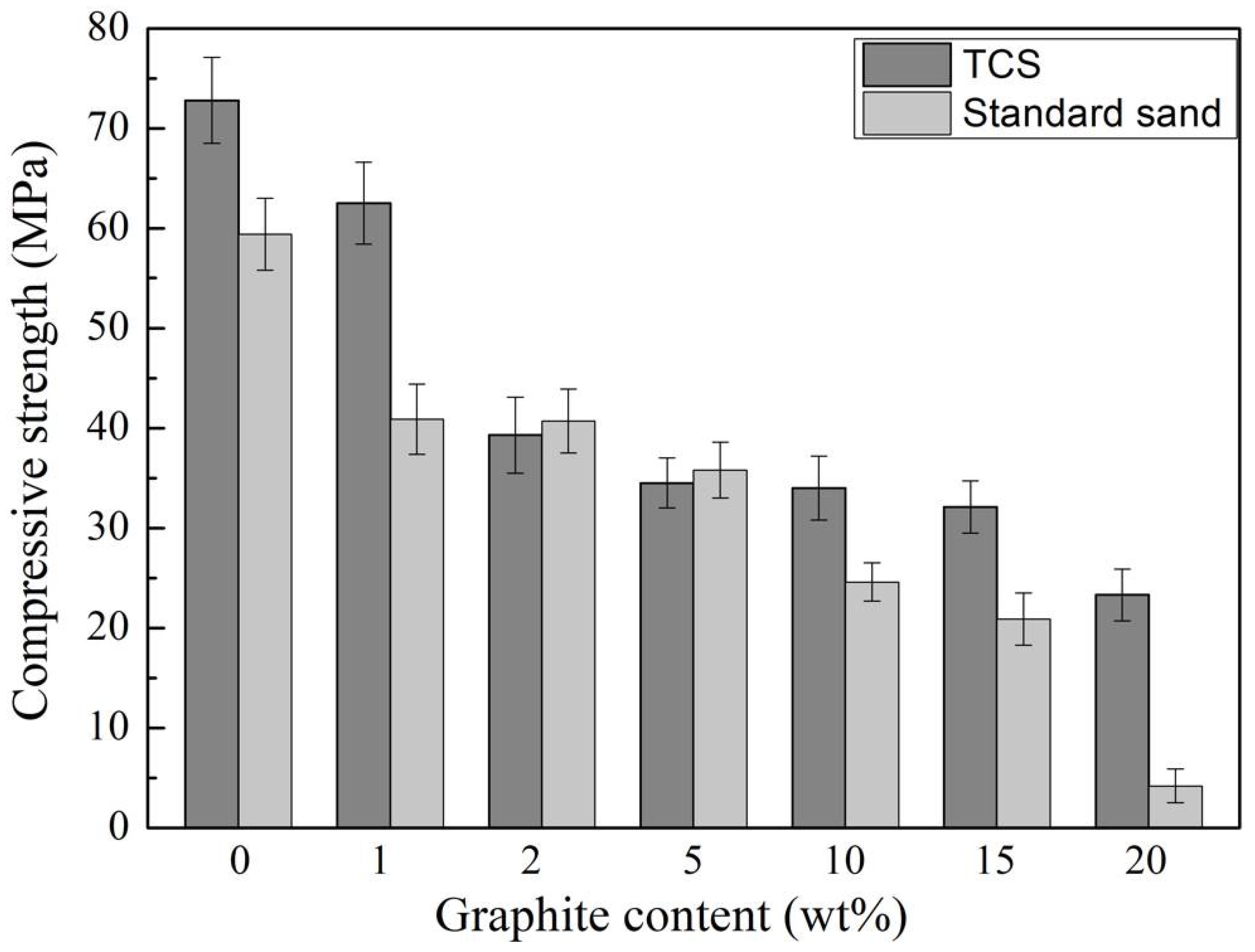
Figure 8 presents the effect of graphite content on the compressive strength of cement mortars cured for 28 days with different aggregates. Without graphite, the compressive strength of cement mortar with TCS as an aggregate is 72.8 MPa, 23% higher than that with standard sand, indicating that the replacement of standard sand with TCS can fully meet the requirements of building cement mortar. The reason why TCS can improve the compressive strength of cement mortar remains to be further explored, but it may be related to the following factors. Firstly, TCS is a ceramic–glass composite prepared at high temperature, which has a higher compressive strength than standard sand. Secondly, TCS contains a small number of active substances that can participate in hydration reaction. TCS is formed by the carbothermic reduction in titanium oxides after adding coke into molten titanium-bearing blast furnace slag. After water quenching, most of the calcium, silicon and aluminum in blast furnace slag form a glassy state in the form of oxides, but a small amount of those exists in the form of crystalline dicalcium silicate, tricalcium silicate, tricalcium aluminate and tetracalcium ferric aluminate, which are active ingredients. Thirdly, as mentioned above, finer aggregates induce a better dispersion of graphite particles, which is also beneficial for the compressive strength.
In the graphite–cement mortar, aggregates are bonded by the hydration products of the cement. Graphite is hydrophobic, and therefore the binding strength at the interfaces with hydrophilic hydration products is low. In addition, graphite is lubricated and has a low compressive strength. Moreover, the addition of graphite induced more water and resulted in more pores in the cement mortar. For the above reasons, the compressive strength of cement mortar decreases with increasing graphite content. According to Figure 8, except at a graphite content of 2–5 wt%, the cement mortar with TCS as an aggregate exhibits much higher compressive strength than that with standard sand. When the graphite content is 20 wt%, the compressive strength of the cement mortar with standard sand as an aggregate has decreased by 93% to 4.2 MPa, which is basically useless for structural application. However, under the same conditions, although the compressive strength of the cement mortar with TCS as an aggregate has dropped by 68%, its value is still as high as 23.3 MPa, suggesting more potential applications.
4. Conclusions
In summary, the present study reports the preparation and properties of conductive graphite–cement mortars with TCS as an aggregate. Compared with those using standard sand as an aggregate, the obtained cement mortars exhibited enhanced compressive strength and electrical conductivity. Based on the above results and discussions, the following conclusions can be drawn:
- (1)
- TCS is a TiC–silicate glass composite with TiC as the conductive filler and the silicate glass phase as the substrate; its low electrical resistivity enables it to serve as a conductive aggregate in cement mortar.
- (2)
- Due to its lower electrical resistivity, the replacement of standard sand with TCS decreased the percolation threshold of conductive graphite–cement mortars from 15 wt% to 10 wt%.
- (3)
- When the graphite content was 10 wt% or higher, the dried graphite–cement mortars exhibited better conductivity than the humid specimens, especially for those with TCS as an aggregate, which could be attributed to the increase in tunnel conductance and the decrease in constant resistance between the conductive particles.
- (4)
- The replacement of standard sand with TCS greatly improved the compressive strength of graphite–cement mortars with 10 wt% or more graphite.
- (5)
- When the graphite content was 10 wt%, the graphite–cement mortar with TCS as an aggregate exhibited excellent properties with a 28 d compressive strength of 34.0 MPa, an electrical resistivity of 4.9 Ω m in humid conditions and 2.9 Ω m in dry conditions, respectively, suggesting its potential application as a structural-functional integrated material.
Author Contributions
Conceptualization, S.R.; methodology, C.T.; investigation, C.T., M.X. and K.D.; resources, S.R.; writing—original draft preparation, C.T.; writing—review and editing, S.R. and M.X.; supervision, S.R.; project administration, S.R. All authors have read and agreed to the published version of the manuscript.
Funding
This research was supported by the National Natural Science Foundation of China (No. U1860102), the University Synergy Innovation Program of Anhui Province (No. GXXT-2020-072 and GXXT-2019-015) and the National Training Program of Innovation and Entrepreneurship for Undergraduates (No. 202110360018S).
Institutional Review Board Statement
Not applicable.
Informed Consent Statement
Not applicable.
Data Availability Statement
The data, presented in this study, are available on request from the corresponding author.
Conflicts of Interest
The authors declare no conflict of interest. The funders had no role in the design of the study; in the collection, analyses, or interpretation of data; in the writing of the manuscript, or in the decision to publish the results.
References
- Zhang, S.; Liu, S.; Ma, W.; Zhu, K.; Dai, Y. Present status and development of comprehensive utilization of vanadium-titanium magnetite. In Rare Metal Technology; Springer: Cham, Switzerland, 2017; Volume 2017, pp. 203–210. [Google Scholar]
- Wang, C.; Lei, Y.; Ma, W.; Qiu, P. An approach for simultaneous treatments of diamond wire saw silicon kerf and ti-bearing blast furnace slag. J. Hazard. Mater. 2021, 401, 123446. [Google Scholar] [CrossRef]
- Fan, G.; Wang, M.; Dang, J.; Zhang, R.; Lv, Z.; He, W.; Lv, X. A novel recycling approach for efficient extraction of titanium from high-titanium-bearing blast furnace slag. Waste Manag. 2021, 120, 626–634. [Google Scholar] [CrossRef]
- Zhang, Z.; Lü, H.; Li, X.; Li, X.; Ran, S.; Chen, Z.; Yang, Y.; Wu, X.; Li, L. Conversion of cati1–xmnxo3–δ-based photocatalyst for photocatalytic reduction of no via structure-reforming of ti-bearing blast furnace slag. ACS Sustain. Chem. Eng. 2019, 7, 10299–10309. [Google Scholar] [CrossRef]
- Zheng, F.; Guo, Y.; Qiu, G.; Chen, F.; Wang, S.; Sui, Y.; Jiang, T.; Yang, L. A novel process for preparation of titanium dioxide from ti-bearing electric furnace slag: Nh4hf2-hf leaching and hydrolyzing process. J. Hazard. Mater. 2018, 344, 490–498. [Google Scholar] [CrossRef]
- Du, Y.; Gao, J.; Lan, X.; Guo, Z. Sustainable recovery of ultrafine tic powders from molten ti-bearing slag under super-gravity field. J. Clean. Prod. 2021, 289, 125785. [Google Scholar] [CrossRef]
- Li, Z.; Lei, Y.; Ma, W.; Zhang, Y.; Wang, C. Preparation of high-purity tisi2 and eutectic si–ti alloy by separation of si–ti alloy for clean utilization of ti-bearing blast furnace slag. Sep. Purif. Technol. 2021, 265, 118473. [Google Scholar] [CrossRef]
- Li, Z.; Xu, C.; Li, Z.; Zhou, Y. The study on smelting ti-si ferroalloy by dc electrothermal process using pisc blast furnace titaniferous slag. J. Chongqing Univ. 1996, 19, 82–86. [Google Scholar]
- Huang, Q.Y.; Lv, X.W.; Huang, R.; Song, J.J. Preparation of Ti–Si–Al alloy by aluminothermic reduction of Tio2 bearing blast furnace slag. Can. Metall. Q. 2013, 52, 413–421. [Google Scholar] [CrossRef]
- Monteiro, A.O.; Costa, P.M.F.J.; Oeser, M.; Cachim, P.B. Dynamic sensing properties of a multifunctional cement composite with carbon black for traffic monitoring. Smart Mater. Struct. 2020, 29, 025023. [Google Scholar] [CrossRef]
- Shishegaran, A.; Daneshpajoh, F.; Taghavizade, H.; Mirvalad, S. Developing conductive concrete containing wire rope and steel powder wastes for route deicing. Constr. Build. Mater. 2020, 232, 117184. [Google Scholar] [CrossRef]
- Frąc, M.; Pichór, W.; Szołdra, P.; Szudek, W. Cement composites with expanded graphite/paraffin as storage heater. Constr. Build. Mater. 2021, 275, 122126. [Google Scholar] [CrossRef]
- Yuan, T.-F.; Choi, J.-S.; Hong, S.-H.; Yoon, Y.-S. Enhancing the electromagnetic shielding and impact resistance of a reinforced concrete wall for protective structures. Cem. Concr. Compos. 2021, 122, 104148. [Google Scholar] [CrossRef]
- Wang, H.; Shi, F.; Shen, J.; Zhang, A.; Zhang, L.; Huang, H.; Liu, J.; Jin, K.; Feng, L.; Tang, Z. Research on the self-sensing and mechanical properties of aligned stainless steel fiber-reinforced reactive powder concrete. Cem. Concr. Compos. 2021, 119, 104001. [Google Scholar] [CrossRef]
- He, Y.; Lu, L.; Jin, S.; Hu, S. Conductive aggregate prepared using graphite and clay and its use in conductive mortar. Constr. Build. Mater. 2014, 53, 131–137. [Google Scholar] [CrossRef]
- Mobili, A.; Giosuè, C.; Bellezze, T.; Revel, G.M.; Tittarelli, F. Gasification char and used foundry sand as alternative fillers to graphene nanoplatelets for electrically conductive mortars with and without virgin/recycled carbon fibres. Appl. Sci. 2020, 11, 50. [Google Scholar] [CrossRef]
- Dong, W.; Guo, Y.; Sun, Z.; Tao, Z.; Li, W. Development of piezoresistive cement-based sensor using recycled waste glass cullets coated with carbon nanotubes. J. Clean. Prod. 2021, 314, 127968. [Google Scholar] [CrossRef]
- Dong, Q.; Wang, G.; Chen, X.; Tan, J.; Gu, X. Recycling of steel slag aggregate in portland cement concrete: An overview. J. Clean. Prod. 2021, 282, 124447. [Google Scholar] [CrossRef]
- Ozturk, M.; Akgol, O.; Sevim, U.K.; Karaaslan, M.; Demirci, M.; Unal, E. Experimental work on mechanical, electromagnetic and microwave shielding effectiveness properties of mortar containing electric arc furnace slag. Constr. Build. Mater. 2018, 165, 58–63. [Google Scholar] [CrossRef]
- Zhen, Y.-L.; Zhang, G.-H.; Chou, K.-C. Carbothermic reduction of titanium-bearing blast furnace slag. High. Temp. Mater. Proc. 2016, 35, 309–319. [Google Scholar] [CrossRef]
- Tang, C.; Xuan, M.; Ding, X.; Ji, Y.; Lv, H.; Zhu, J.; Wang, D.; Deng, X.; Ran, S. Effects of carbonized titanium-bearing blast furnace slag on the compressive strength and electrical resistivity of cement mortar. Chin. J. Process. Eng. 2021, 22, 499–505. (In Chinese) [Google Scholar]
- Doo-Yeol, Y.; You, I.; Seung-Jung, L. Electrical properties of cement-based composites with carbon nanotubes, graphene, and graphite nanofibers. Sensors 2017, 17, 1064–1076. [Google Scholar]
- Zheng, Q.; Han, B.; Cui, X.; Yu, X.; Ou, J. Graphene-engineered cementitious composites. Nanomater. Nanotechno. 2017, 7, 184798041774230. [Google Scholar] [CrossRef]
- D’Alessandro, A.; Materazzi, A.L.; Ubertini, F. Nanotechnology in Cement-Based Construction; CRC Press: Boca Raton, FL, USA, 2020. [Google Scholar]
- Lamastra, F.R.; Chougan, M.; Marotta, E.; Ciattini, S.; Ghaffar, S.H.; Caporali, S.; Vivio, F.; Montesperelli, G.; Ianniruberto, U.; Al-Kheetan, M.J.; et al. Toward a better understanding of multifunctional cement-based materials: The impact of graphite nanoplatelets (gnps). Ceram. Int. 2021, 47, 20019–20031. [Google Scholar] [CrossRef]
- Zhou, Z.; Xie, N.; Cheng, X.; Feng, L.; Hou, P.; Huang, S.; Zhou, Z. Electrical properties of low dosage carbon nanofiber/cement composite: Percolation behavior and polarization effect. Cem. Concr. Compos. 2020, 109, 103539. [Google Scholar] [CrossRef]
Figure 1.
Specimen and electrode configuration.
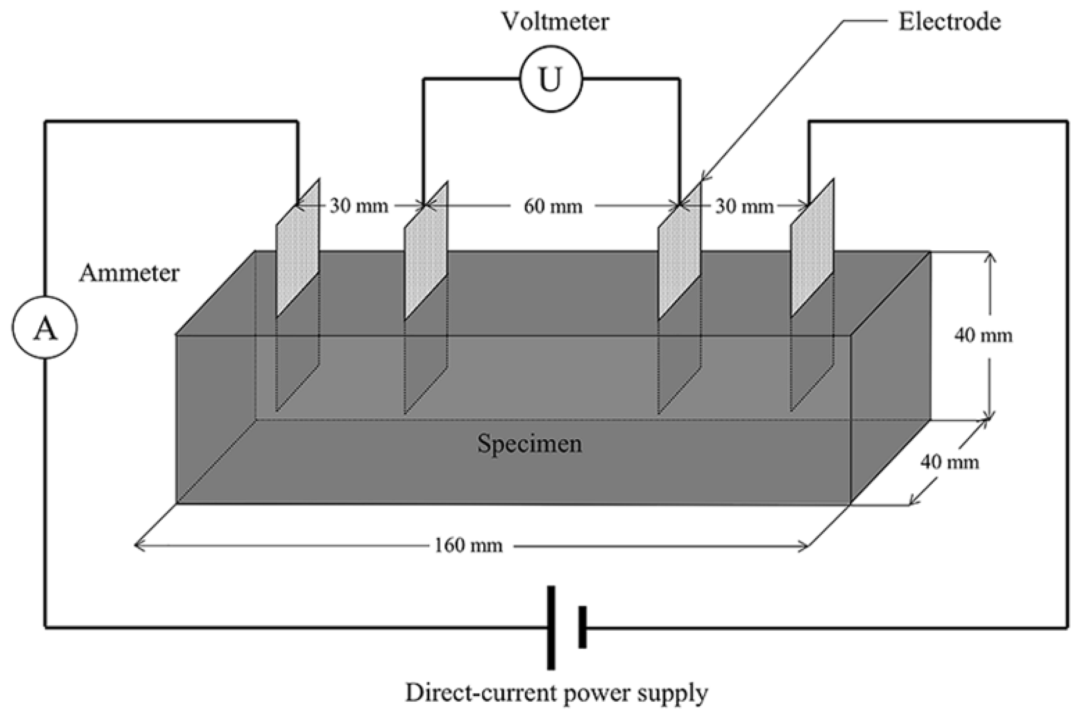
Figure 2.
(a) XRD pattern of TCS, (b) comparison of grain size cumulative curves for TCS and standard sand.
Figure 2.
(a) XRD pattern of TCS, (b) comparison of grain size cumulative curves for TCS and standard sand.
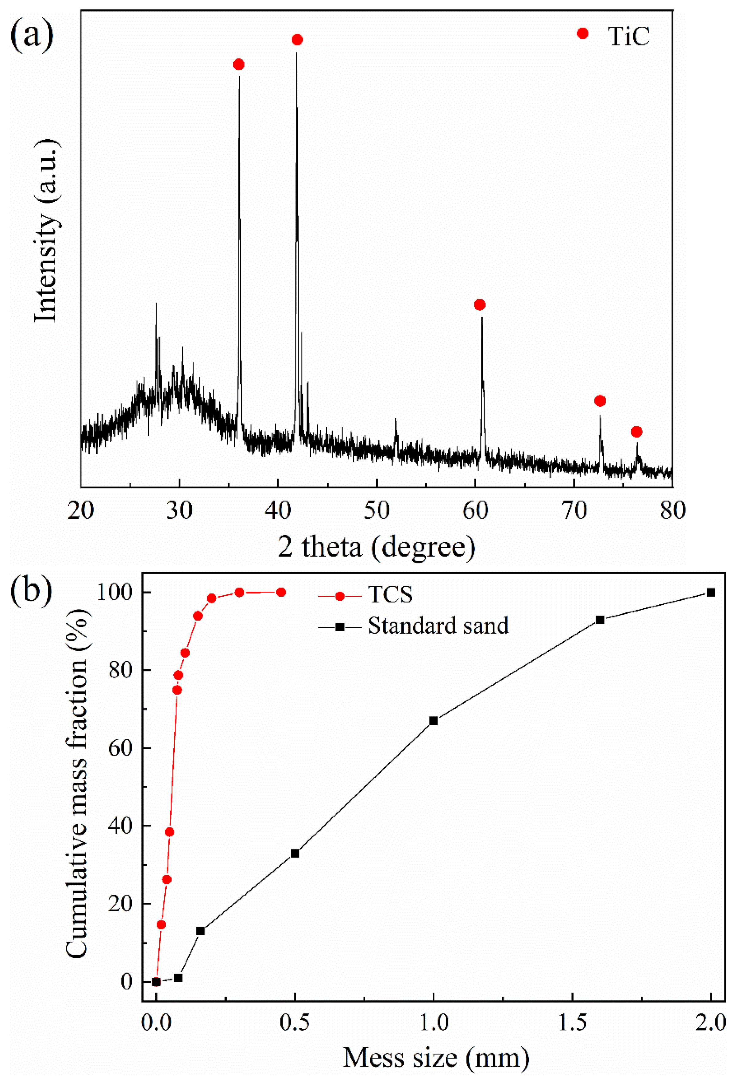
Figure 3.
(a) low magnitude, (b) high magnitude SEM images of TCS powder; (c) C, (d) O and (e) Ti elemental mapping of (b).
Figure 3.
(a) low magnitude, (b) high magnitude SEM images of TCS powder; (c) C, (d) O and (e) Ti elemental mapping of (b).
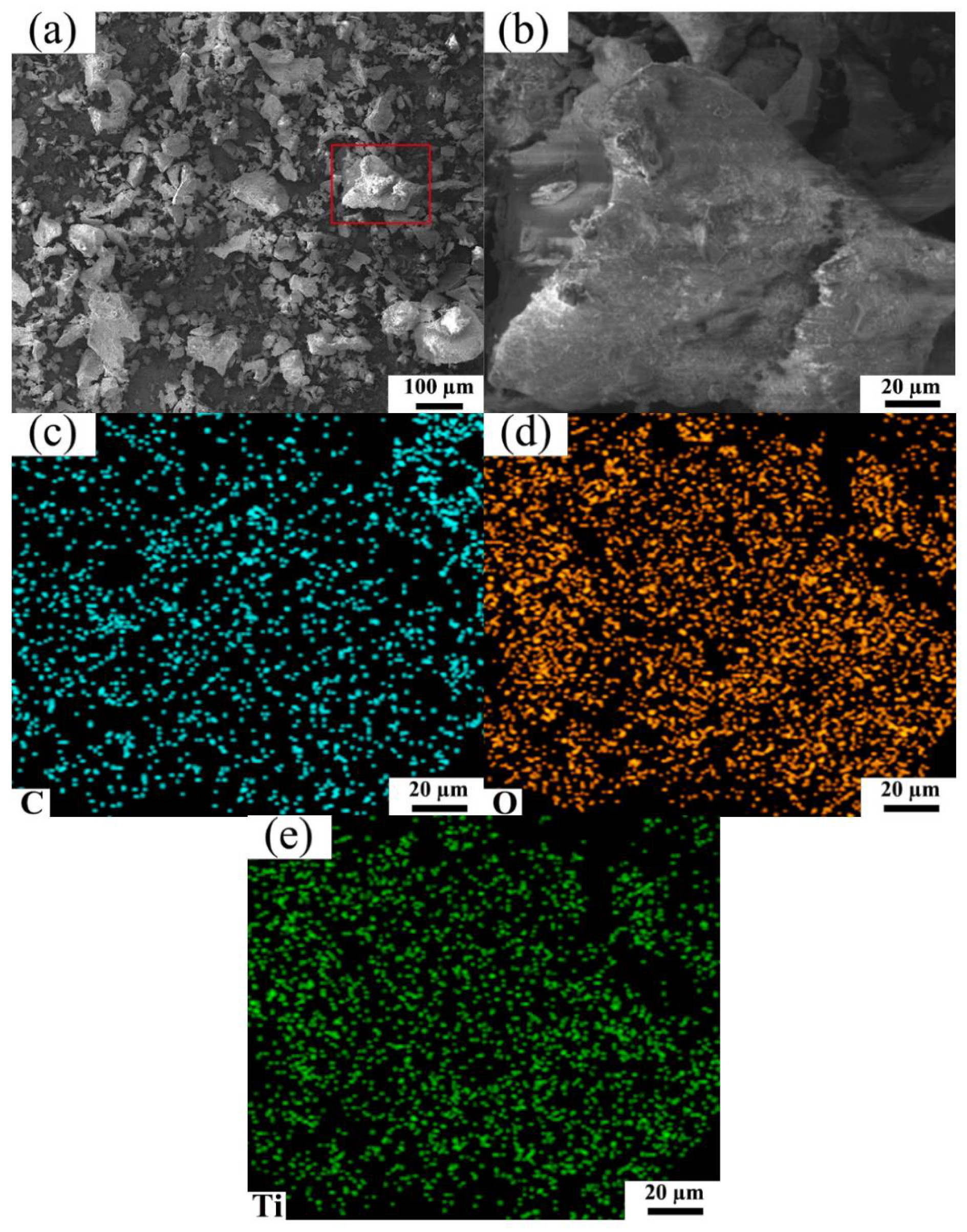
Figure 4.
Effect of graphite content on the electrical resistivity of cement mortars cured for 3, 7 and 28 days with (a) TCS, and (b) standard sand as an aggregate.
Figure 4.
Effect of graphite content on the electrical resistivity of cement mortars cured for 3, 7 and 28 days with (a) TCS, and (b) standard sand as an aggregate.
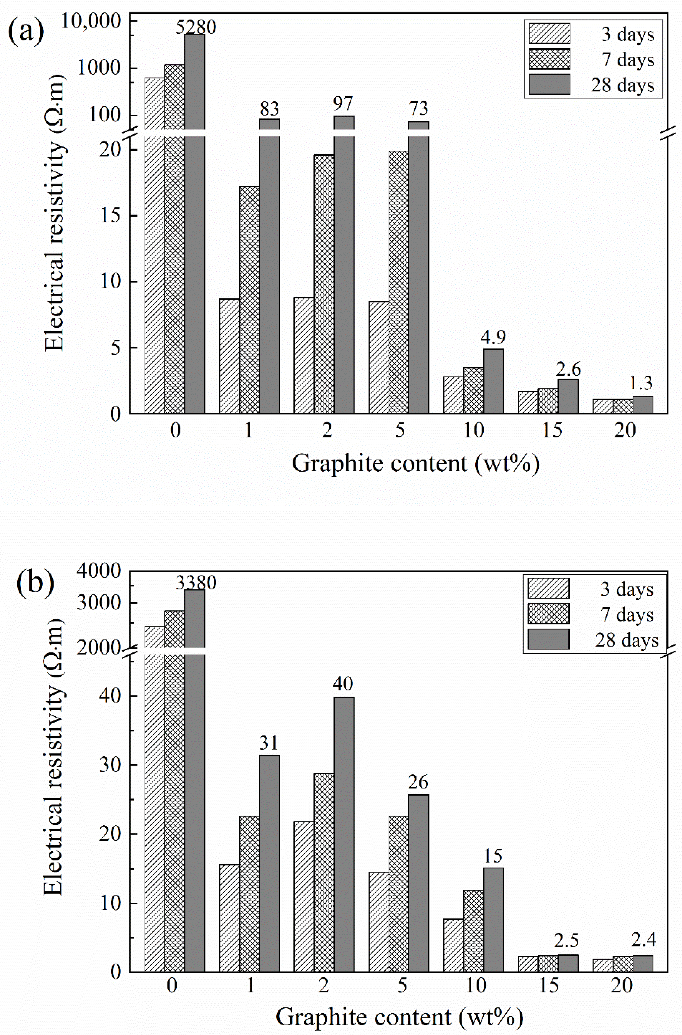
Figure 5.
Effect of graphite content on the electrical resistivity of dried cement mortars with different aggregates.
Figure 5.
Effect of graphite content on the electrical resistivity of dried cement mortars with different aggregates.
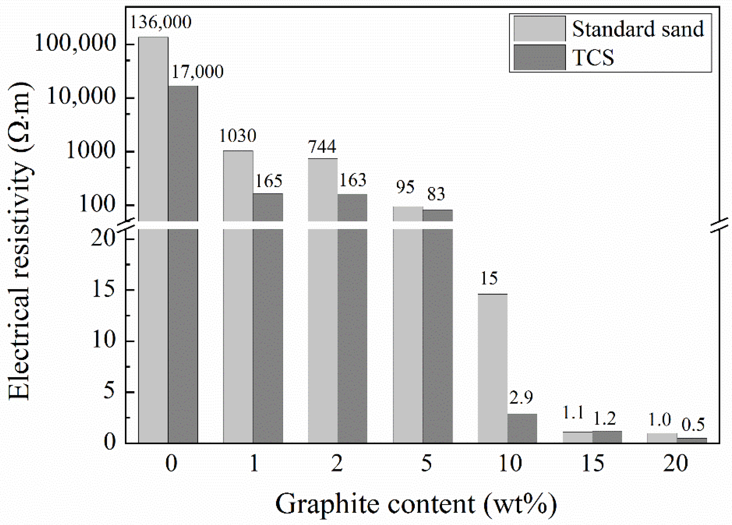
Figure 6.
(a) SEM image and (b) C, (c) O, (d) Ti elemental mapping of graphite–cement mortar with TCS as an aggregate.
Figure 6.
(a) SEM image and (b) C, (c) O, (d) Ti elemental mapping of graphite–cement mortar with TCS as an aggregate.
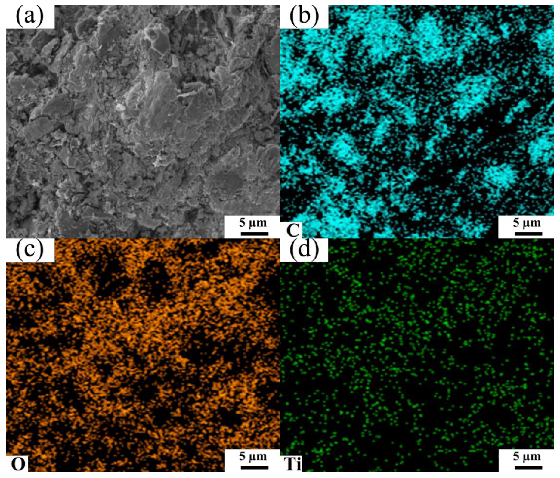
Figure 7.
(a) SEM image and (b) C elemental mapping of graphite–cement mortar with standard sand as an aggregate.
Figure 7.
(a) SEM image and (b) C elemental mapping of graphite–cement mortar with standard sand as an aggregate.
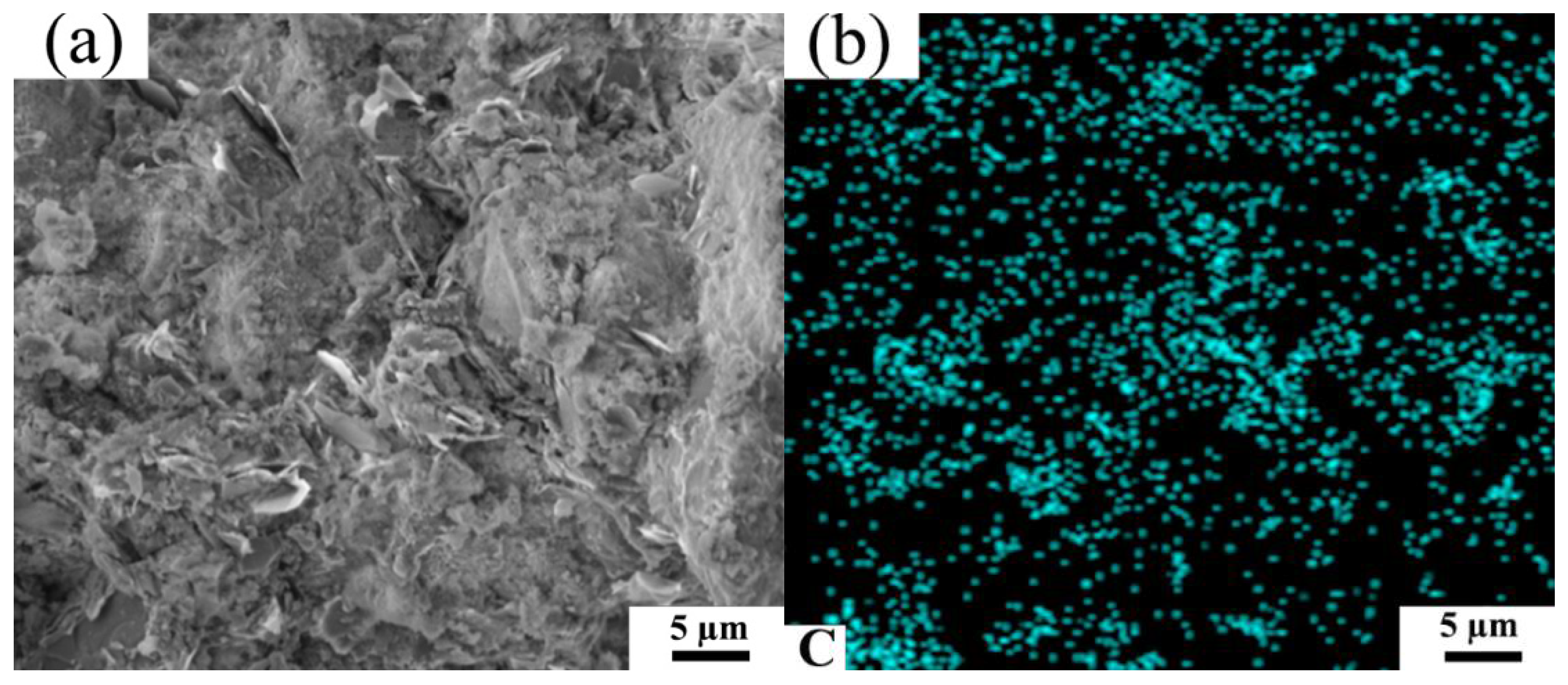
Figure 8.
Effect of graphite content on the compressive strength of cement mortars cured for 28 days with different aggregates.
Figure 8.
Effect of graphite content on the compressive strength of cement mortars cured for 28 days with different aggregates.

Table 1.
Mix proportion of graphite–cement mortar.
| Specimen | Graphite Content (wt%) | Cement (g) | TCS (g) | Standard Sand (g) | Graphite (g) | Water (g) |
|---|---|---|---|---|---|---|
| C0 | 0 | 450 | 1350 | 0 | 0 | 225 |
| C1 | 1 | 450 | 1332 | 0 | 18 | 225 |
| C2 | 2 | 450 | 1314 | 0 | 36 | 375 |
| C3 | 5 | 450 | 1260 | 0 | 90 | 385 |
| C4 | 10 | 450 | 1170 | 0 | 180 | 397 |
| C5 | 15 | 450 | 1080 | 0 | 270 | 425 |
| C6 | 20 | 450 | 990 | 0 | 360 | 485 |
| S0 | 0 | 450 | 0 | 1350 | 0 | 225 |
| S1 | 1 | 450 | 0 | 1332 | 18 | 225 |
| S2 | 2 | 450 | 0 | 1314 | 36 | 375 |
| S3 | 5 | 450 | 0 | 1260 | 90 | 385 |
| S4 | 10 | 450 | 0 | 1170 | 180 | 397 |
| S5 | 15 | 450 | 0 | 1080 | 270 | 425 |
| S6 | 20 | 450 | 0 | 990 | 360 | 485 |
Table 2.
XRF analysis of TCS.
| Component | Si | Ca | Ti | Al | Mg | Fe | Mn | K | Na | V | Loss on Ignition |
|---|---|---|---|---|---|---|---|---|---|---|---|
| Content (wt%) | 12.26 | 18.42 | 11.41 | 8.72 | 4.67 | 1.45 | 0.41 | 0.22 | 0.36 | 0.14 | 1.17 |
Publisher’s Note: MDPI stays neutral with regard to jurisdictional claims in published maps and institutional affiliations. |
© 2022 by the authors. Licensee MDPI, Basel, Switzerland. This article is an open access article distributed under the terms and conditions of the Creative Commons Attribution (CC BY) license (https://creativecommons.org/licenses/by/4.0/).
Share and Cite
MDPI and ACS Style
Tang, C.; Xuan, M.; Deng, K.; Ran, S. Enhanced Strength and Electrical Conductivity in Graphite-Cement Mortars with Carbonized Titanium-Bearing Blast Furnace Slag as an Aggregate. Metals 2022, 12, 754. https://doi.org/10.3390/met12050754
AMA Style
Tang C, Xuan M, Deng K, Ran S. Enhanced Strength and Electrical Conductivity in Graphite-Cement Mortars with Carbonized Titanium-Bearing Blast Furnace Slag as an Aggregate. Metals. 2022; 12(5):754. https://doi.org/10.3390/met12050754
Chicago/Turabian StyleTang, Chenjun, Ming Xuan, Kexing Deng, and Songlin Ran. 2022. "Enhanced Strength and Electrical Conductivity in Graphite-Cement Mortars with Carbonized Titanium-Bearing Blast Furnace Slag as an Aggregate" Metals 12, no. 5: 754. https://doi.org/10.3390/met12050754
Note that from the first issue of 2016, this journal uses article numbers instead of page numbers. See further details here.