1. Introduction
Refractory linings used on ladles, tundish, entry nozzles and many other parts, which may come into contact with molten steel, are usually additionally protected from thermal shocks with oxide-based coatings. These multicomponent clay mixtures are mainly based on ZrO
2 with smaller amounts of Al
2O
3, MgO and SiO
2 oxides as well as sodium and fluoride compounds [
1,
2,
3]. Apart from the oxide ceramics mentioned above, recycled ashes, i.e., the typical waste by-product of coal-run power plants, are also admixed with such clays. In this way, they benefit from a large volume of fly ash and cenospheres, which have been reported to considerably improve cementitious performance [
4,
5]. Usually, all such powders are mixed with water and then applied on the working surfaces by immersion or by spraying. Following deposition, due to its low green strength, a coating material is vulnerable to cracking and delamination. The risk of development of such defects increases further throughout the drying process and is subsequently aggravated even more during the transport to the steel mill. Despite much caution being taken for appropriate handling, damage to the protective coating is easily incurred and, therefore, an improvement in the green strength of such coating material would be greatly appreciated. Therefore, an improvement in the mechanical properties of the coatings deposited over the refractory linings is critical for ensuring a safe and uninterrupted production flow with minimum material waste.
The high susceptibility to cracking of such coatings could be significantly diminished by the addition of ceramic or polymer fibers. It has been demonstrated that such additives into cementious or refractory ceramic materials improve both their compressive strength from ~30% up to ~200% [
6,
7] as well as the thermal shock resistance under thermal cycling [
8,
9]. What is more, it has been reported that concrete with polypropylene fiber addition shows a more porous microstructure relative to fiber-less ones. This can have an effect on gas permeability, facilitating water evaporation. Although in general advantageous, larger fiber additions can result in mixing and spraying difficulties due to their entanglement. Thus, a precise control of the amount as well as knowledge of the effect of fibers on mass rheology is necessary [
8,
9]. The main requirement is thus that the fibers should easily mix with the slurry being prepared for application, but without compromising its required fluidity [
10,
11]. The ceramic fibers, such as alumina (Al
2O
3) Saffil™, may at first seem an evident choice [
12,
13]. However, as they are relatively expensive to purchase as well as posing a respiratory health hazard, their introduction into a full scale production route needs a detail assessment of all the problems connected with it. On the other hand, the polymer fibers already proved to be a beneficial addition to the materials used for the production of investment casting molds, as they turned out to be very effective in resisting corner cracking [
12].
Therefore, the main aim of the present work is to characterize the microstructure and chemical composition of the main components of the clay-based coating routinely applied on refractory ceramics. Secondly, the effect of the addition of the polypropylene fibers into the mixture of MgO, SiO2 and cenosphere basic slurry on their water release during the drying stage and the eventual improvement concerning the resistance to mechanically inflicted crumbling is investigated.
2. Materials and Methods
The powder containing clay, alumina, cenospheres, aluminium powder, fused silica, chamotte, elastomeric styrene, dextrin and acrylic emulsifying agents (rest) used to prepare a protective coating over refractory ceramic under the name Thermacoat™ was supplied by Vesuvius Poland Company. The standard procedure used to apply such coating on ceramic parts is performed by immersion, which requires the mixing of the powders with water until they reach the semi-liquid state. The cenosphere powders were acquired from EKO Export SA. Their density (dried at 105 °C) is close to 0.7 g/cm3, while melting temperature extends from 1260 °C up to 1560 °C. The polypropylene fibers used in this experiment were purchased commercially under the Belmix™ brand name (EN 148889-2:2006). They are characterized by a melting point of 164 °C, a density of 0.91 g/cm3, ~34 μm diameter and length of 12 mm.
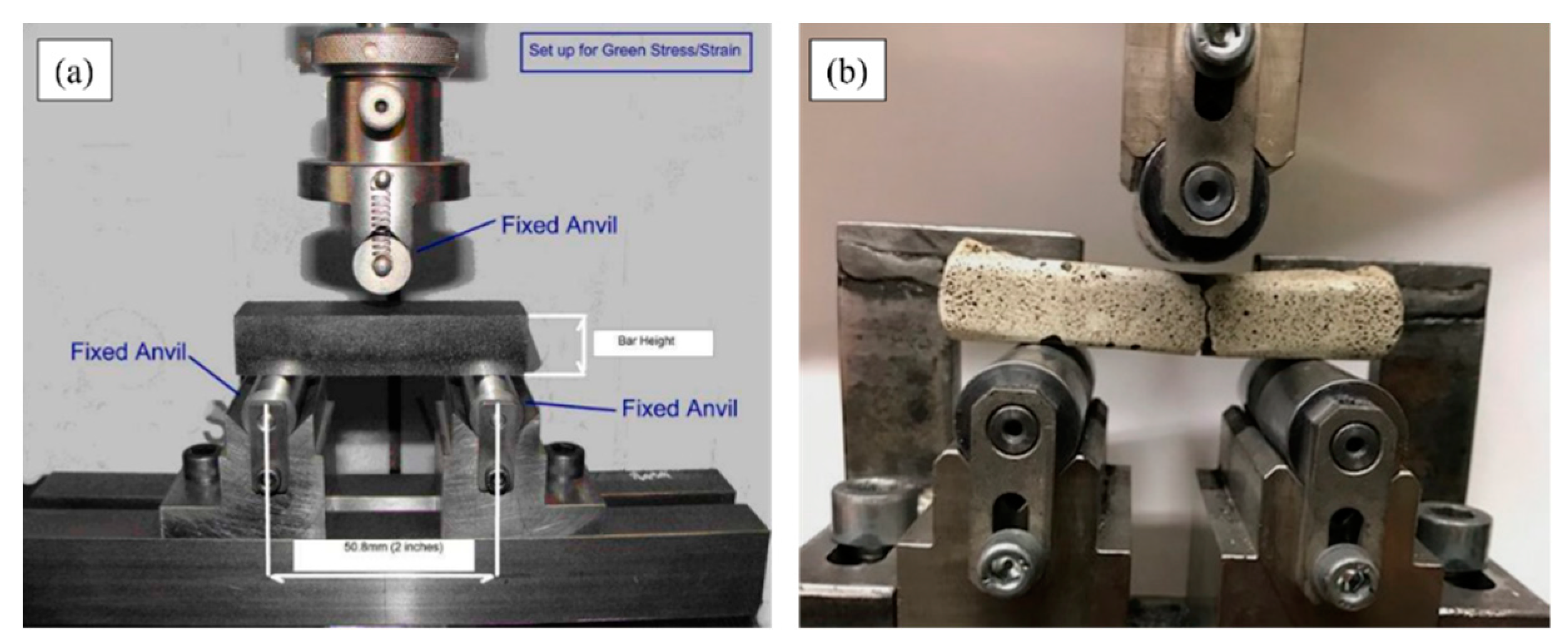
The microstructure investigation of the dried samples of Thermacoat™ with varying amounts either of cenospheres or polypropylene fibers was performed with light microscopy (LM) using an Olympus KL as well as a scanning electron microscope (SEM), using Scios II Dual Beam equipped with EDAX X-ray energy dispersive spectroscopy (EDS) analyzer. The weight losses during the sample drying stage and the subsequent heating up to 800 °C stage were measured using thermogravimetric analysis (TGA) by Mettler Toledo, while the heat flow during that process was followed with the differential scanning calorimetry (DSC) method using Q1000 by TA Instruments. Both measurements were performed at a rate of 20 K/min. XRD examination was performed on the Philips diffractometer (PW1710; PW1830) X’Pert system using monochromated Co Kα radiation. The mechanical properties of the samples were tested using the three-point flex test with a TIRA 2820 stand produced by TIRA GmBH. The samples for this test were prepared in the form of rods of 15 cm length and a 15 × 15 mm cross-section. Both for the plain Thermacoat™ and for the mixtures with fiber additions, four of such specimens were tested in each case. The travers run during this experiment was set up to 5 mm and the maximum force range was limited to 50 N.
3. Results and Discussion
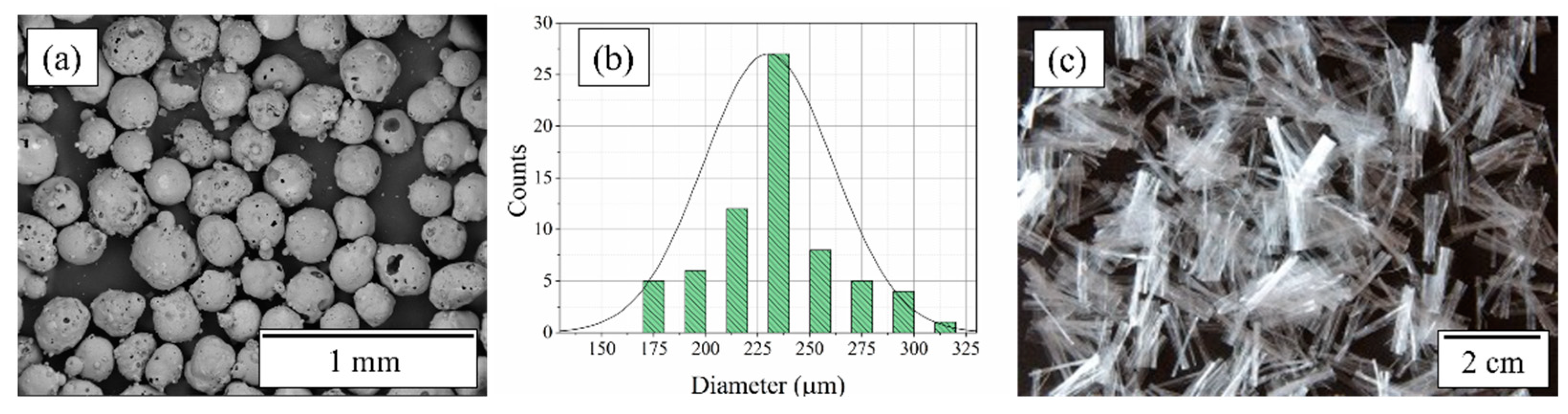
The microstructure and morphology of the cenospheres as well as polypropylene fibers used as additions into the standard Thermacoat™ mix are shown in
Figure 1. The cenospheres are largely hollow with an uneven surface (
Figure 1a). They range in diameter from ~70 µm to ~450 µm, with an average diameter of 230 µm (
Figure 1b), which is in agreement with the literature [
14,
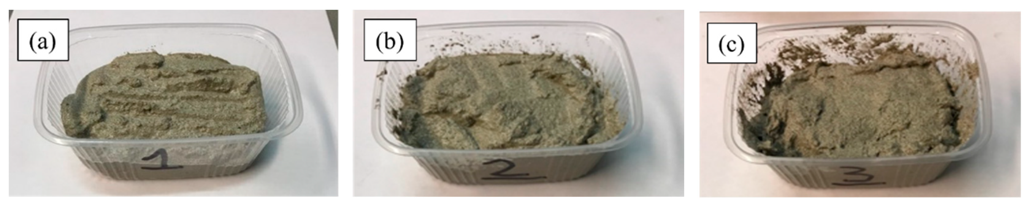
15]. The polypropylene fibers showed a more uniform size distribution consistent with their technical specifications, as given in the Materials and Methods Section. The stirring of the Thermacoat™ powder with water added at a ratio of 98:6 allows to obtain a slurry with fluidity optimized up to a level, which allows covering ceramic parts by immersion. It could be kept in that form also with up to 2.5 wt.% of cenospheres or 1.5 wt.% of polypropylene fibers, i.e., to keep such mixtures still in a semi-liquid /slurry type consistency (
Figure 2). Above these limits, the respective mixtures turn prevailingly solid, i.e., preserve the given shape (making coatings by submersion ineffective). The elaborated limits could be easily extended by adding more water, but such a change would increase the material shrinkage and cracking during the drying stage. Additionally, it would negatively affect the overall production costs, in terms of time and energy expenditure.
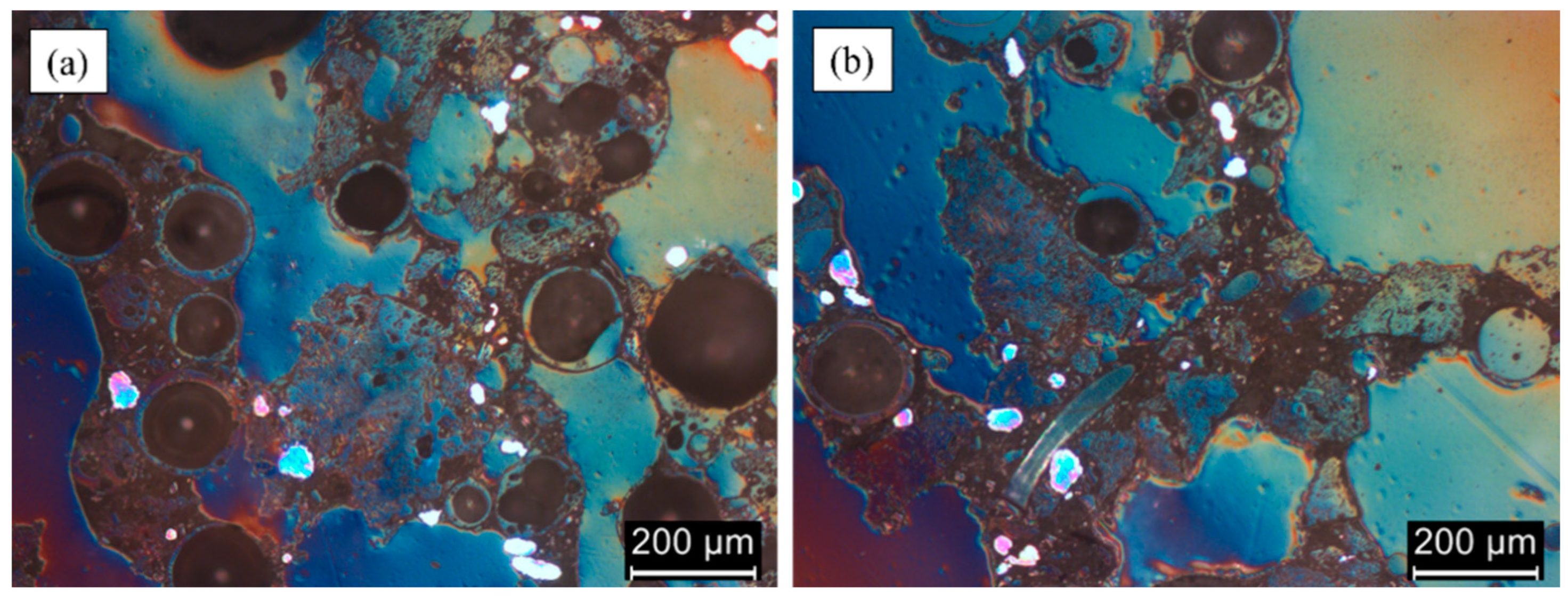
The microstructure characterization using light microscopy (LM) of the investigated mixtures, due to their high brittleness in a dry state, was performed by crushing them into small pieces and then stabilizing with a polymeric resin. Only then it was possible to produce their sections suitable for polishing and subsequent LM observations. The polymeric resin can be easily distinguished from the solidified chunks of the investigated materials at LM images (
Figure 3a,b) due to their bluish color. The performed observations confirmed that both the cenospheres and polypropylene fibers were well dispersed within the plain cement-type powders of the Thermacoat™ (
Figure 3a,b).
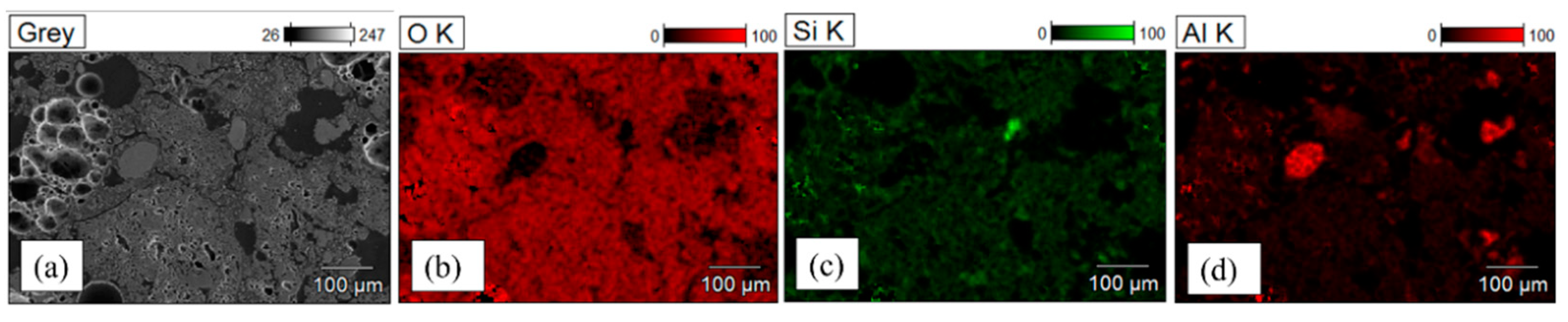
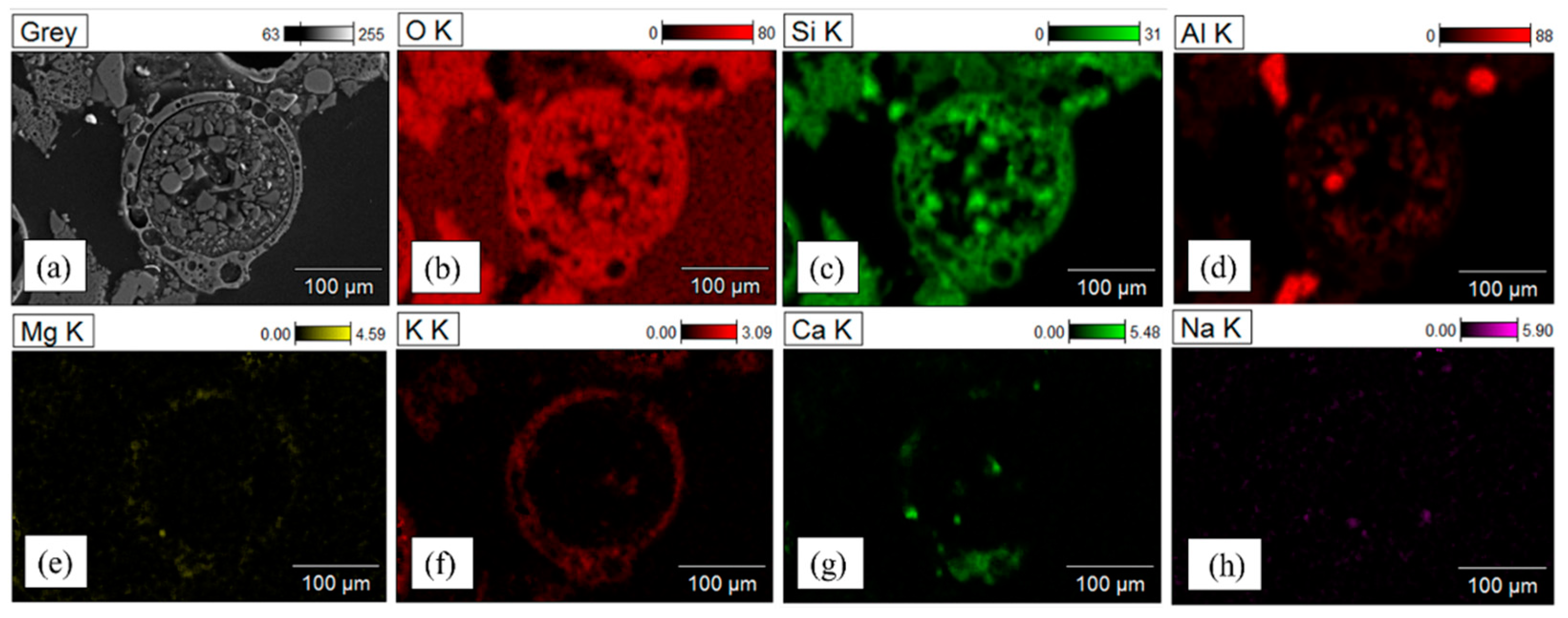
The SEM secondary electron (SE) observations coupled with the EDS analysis of the local chemical composition confirm that the major components of the Thermacoat™ are silicon and oxygen (
Figure 4).
Figure 4 presents an area chosen for analysis together with the corresponding elemental distribution maps. The evident separation of these elements confirms that the respective areas correspond to SiO
2- and Al
2O
3-rich components. Additionally, the presence of aluminum particles of the size of ca. 100 μm was confirmed (in the LM images, they were visible as white/magenta particles). Simultaneously, these observations showed that some cenospheres are punctured and in consequence filled with particles of the Thermacoat™ powders (
Figure 5). The cenosphere walls are built mainly of silicon oxide, but minor amounts of Mg, K, Ca and Na were also detected.
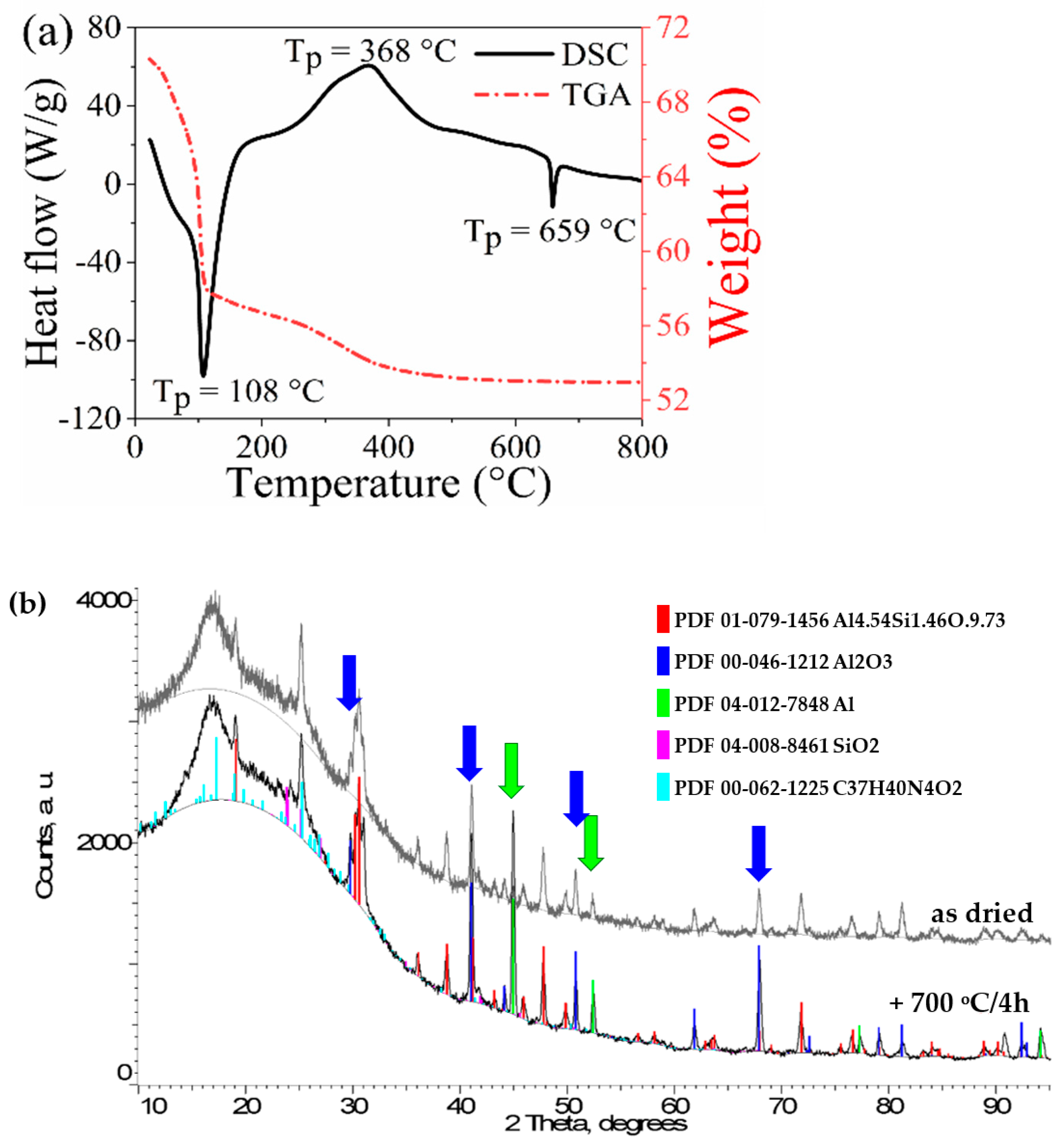
The thermal response of the investigated materials was evaluated by TGA/DSC methods. First the dried Thermacoat™ without any admixtures, i.e., in a form in which it is normally applied on various parts in the steel plant, was subjected to heating up to 800 °C. During that process, the weight loss (TGA) and heat flow (DSC) were recorded simultaneously (
Figure 6). The curve representing the former shows that the heating of the Thermacoat™ at the beginning results in a strong mass loss due to water evaporation (
Figure 6a). Continued heating above 100 °C leads to further diminishing of the measured weight, but at a much slower rate. The small increase in mass loss recorded at ~300 °C is connected with an accelerated loss of volatile oxidized components. The latter process slows down above 400 °C and practically terminates at 500 °C. The DSC curve shows an endothermic narrow peak matching weight loss, corresponding to water evaporation, which is followed by a wide exothermic peak (T
p = 368 °C) resulting, most likely, from the burning out of organic materials. At an even higher temperature range, the presence of a relatively small and narrow endothermic effect (T
p = 659 °C) was also detected. In that range, in addition to the melting of aluminum particles, the amorphous-to-crystalline phase transformation of some multicomponent additions might take place [
16,
17].
In order to clarify the nature of this effect, a small portion of the as-prepared Thermacoat™ was heated up to 700 °C, kept at that temperature for 4 h, and slowly cooled to ambient temperature. The XRD spectra of the as-prepared Thermacoat™ sample and the one subjected to the above specified heat treatment are shown in
Figure 6b (grey line). The high background at the low 2Theta angular range results from the presence of nano-crystalline and amorphous material, which are also part of cenospheres [
15]. The peaks on these spectra correspond to lines characteristic of mullite (Pbam), α-Al
2O
3 corundum (R-3c), aluminum (Fm-3m), tridymite (Cc) and quartz (P3221), which are in acordance with SEM/EDS results. Comparing the XRD profiles of the as-dried with the heat-treated powders (
Figure 6b: grey against, respectively, black lines), it seems that there was no major mineral change in the mixture, except a slightly raised signal in the soft radiation range, resulting, most likely, from hydride decomposition. The other difference between both spectra is that connected with the disappearance of a strong peak at ~45 deg and a medium–strong one at ~52.5 deg, corresponding to the (111) and (200) α-Al lines (marked with green arrows). This could be related to the melting of the aluminum particles, which was separately supported by the presence of an endothermic peak at around 659 °C on the DSC curve in
Figure 6a. The transformation of aluminum from the solid state to liquid should involve its reaction with cenospheres, resulting in damping mullite and quartz peaks on account of the raised representation of the α-Al
2O
3 phase [
15,
17]. Due to the dissipation of the diffracted signal to a multiplicity of lines from the two former phases, the changes in strength are difficult to assess, though the increase in the signal from the corundum (marked with blue arrows) is evident, confirming that such reactions indeed take place, i.e.,
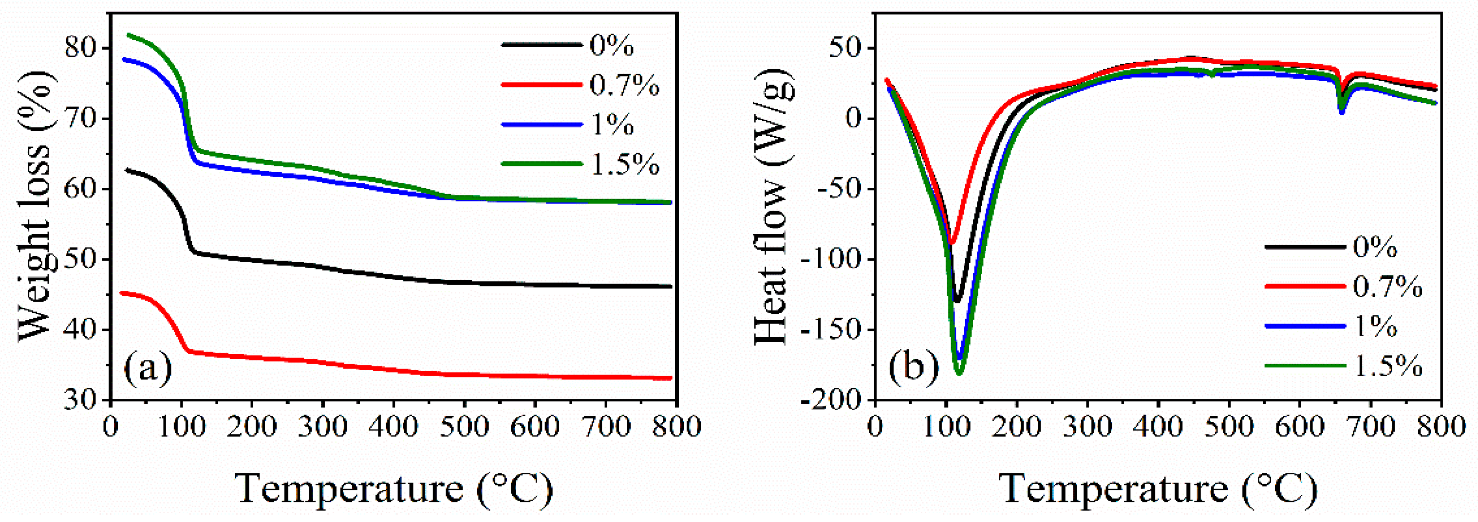
The TGA measurements of the weight loss during the heating of the Thermacoat™ with up to 1.5% of polypropylene fiber additions showed a similar thermal behavior, except for the level of weight loss (
Figure 7a). The latter was probably caused by a faster water evaporation facilitated by the presence of polypropylene fibers, i.e., a situation similar to that observed by da Luz et al. [
18].
The DSC measurements of the samples bearing polypropylene fibers again showed two narrow endothermic peaks exactly at the same temperatures as that recorded for the plain Thermacoat™, i.e., without fiber addition (
Figure 7b). However, the exothermic peaks, this time, were much lower and extended over the wider temperature range, practically merging with the background line. Such differences may arise from the small fluctuations in the composition of the basic Thermacoat™. In addition to the above discrepancy, the presented part of the experiment indicates that the introduction of polymer fibers into the Thermacoat™ is indeed facilitating easier water evaporation. Simultaneously, such addition has no effect on the phase composition of this multi-component material within the investigated temperature range.
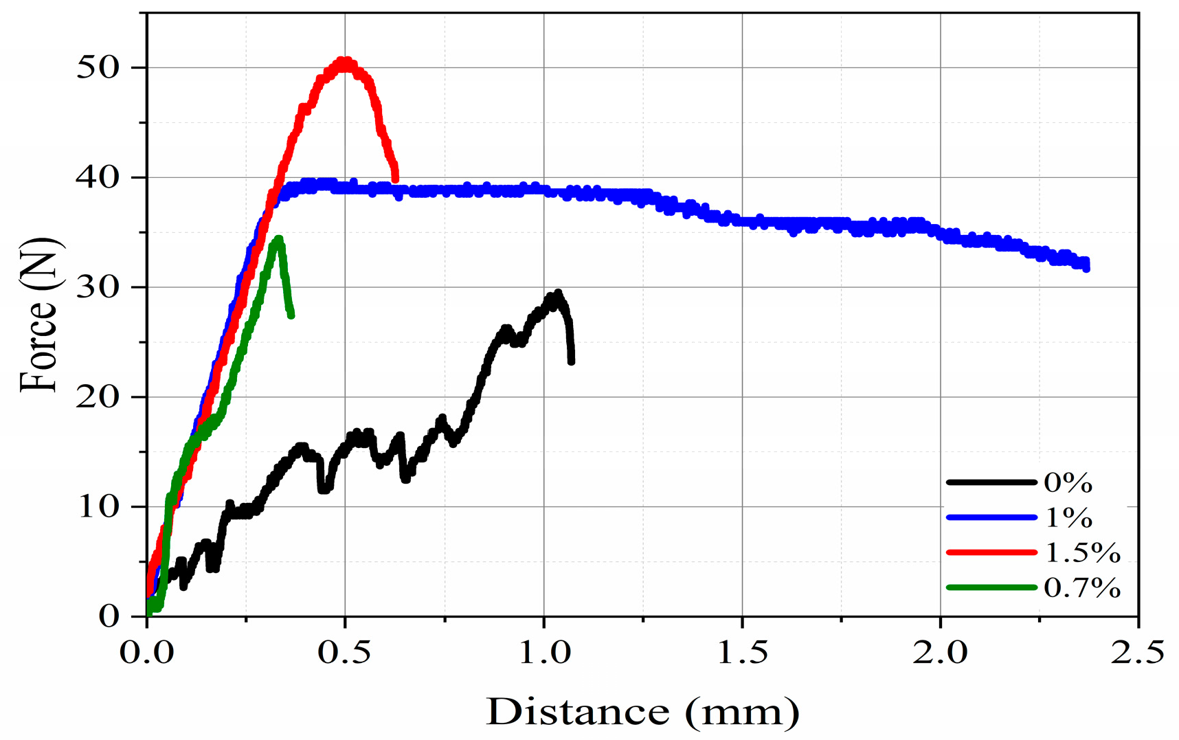
The measurements of flexural strength of the as-dried plain Thermacoat™ samples showed a significant scatter of the force values registered during the advancement of the travers of the testing rig (
Figure 8 and
Figure 9).
It was connected with the recurrent nucleation and propagation of cracks developing under the progressive down-movement of the anvil pressing against the tested sample. Usually, a resistance-less penetration takes place at the start of such test of the plain Thermacoat™ material, but, occasionally, it also takes place in the case of the sample with the 0.7% addition of the polymer fibers. It might be connected with an inhomogeneous distribution of cenospheres (aggregating into easily collapsing colonies) as well as mushy organic matter. It should be pointed out that the strain–stress curves of mineral samples are usually of a jagged character and the addition of cenospheres only aggravates this situation [
19]. On the other hand, samples with ~1% of these fibers were not only more resistant to anvil penetration at the start of the test, but also they were more reproducible in their behavior. The measurements of the force increments with the traversed length helped to determine the ultimate flexural strength at ~0.2 MPa. The large addition (1.5 wt.%) of this type of fibers into the Thermacoat™ again resulted in recurrent scatter of results and with frequent zero resistance at the start of the test. This problem was noted for both the plain Thermacoat™ and, on a smaller scale, for that carrying a low fiber content. Therefore, the renewed susceptibility to cracking of the sample with a high fiber content in the present case was probably a direct result of the increasing problems with fiber mixing, resulting in the homogeneities of their distribution, which are also known from other works [
20,
21,
22]. On the other hand, in the paper published by Lv et al. [
6], an optimum reinforcement for similar matrix material (cemented sand) was determined at 1.5 wt.% addition of polypropylene fibers. The difference between their and the presently determined optimum fiber addition is relatively small and may result partly from differences in the wetting of these fibers by the matrix components and partly by differences in fiber dimensions. In addition to the above, the improvement in the flexural strength of the Thermacoat™ carrying fibers could be much higher than that determined in the present experiment of ~0.2 MPa, as long as the fibers are aligned perpendicularly to the direction of the acting force, as in the work by Kumara et al. [
23].


