Review

Variable Speed Diesel Generators: Performance and Characteristic Comparison

by
Mohammadjavad Mobarra
1,*,
Miloud Rezkallah
2 and
Adrian Ilinca
1
1
Wind Energy Research Laboratory (WERL), Université du Québec à Rimouski, Rimouski, QC G5L 3A1, Canada
2
Electrical Engineering Department, Ecole de Technologie Superieure, Montreal, QC H3C 1K3, Canada
*
Author to whom correspondence should be addressed.
Energies 2022, 15(2), 592; https://doi.org/10.3390/en15020592
Submission received: 5 December 2021 / Revised: 28 December 2021 / Accepted: 1 January 2022 / Published: 14 January 2022
(This article belongs to the Special Issue Failure Diagnosis and Prognosis of Induction Machines)

Abstract

:
Diesel generators (DGs) are set to work as a backup during power outages or support the load in remote areas not connected to the national grid. These DGs are working at a constant speed to produce reliable AC power, while electrical energy demand fluctuates according to instantaneous needs. High electric loads occur only for a few hours a day in remote areas, resulting in oversizing DGs. During a low load operation, DGs face poor fuel efficiency and condensation of fuel residues on the walls of engine cylinders that increase friction and premature wear. One solution to increase combustion efficiency at low electric loads is to reduce diesel engine (DE) speed to its ideal regime according to the mechanical torque required by the electrical generator. Therefore, Variable Speed Diesel Generators (VSDGs) allow the operation of the diesel engine at an optimal speed according to the electrical load but require additional electrical equipment and control to maintain the power output to electrical standards. Variable speed technology has shown a significant reduction of up to 40% fuel consumption, resulting in low GHG emissions and operating costs compared to a conventional diesel generator. This technology also eliminates engine idle time during a low load regime to have a longer engine lifetime. The main objective of this survey paper is to present the state of the art of the VSDG technologies and compare their performance in terms of fuel savings, increased engine lifetime, and reduced greenhouse gases (GHG) emissions. Various concepts and the latest VSDG technologies have been evaluated in this paper based on their performance appraisal and degree of innovation.

Graphical Abstract

1. Introduction

Despite all improvements in renewable energy technologies, numerous remote sites and applications are still dependent on DGs and fossil fuels to produce electricity. DGs are still commonly used to provide electricity in isolated communities as renewable energies are unpredictable, intermittent, and the storage capacity is limited [1].
DGs are also widely used as a backup in countries with a high frequency of electric shortage both for residential and commercial sectors, and as a primary source of energy production in some power plants. Stability, reliability, and ease of production are some of the advantages of DGs for electricity generation [1]. On the other hand, diesel engines have some major drawbacks, such as greenhouse gas (GHG) emissions and high fuel consumption. Nitrogen oxides (NOx) and carbon monoxide (CO) are two hazardous and destructive gases produced during incomplete diesel combustion, among other particulate emissions [2,3]. Extensive research and several studies have been carried out, such as post-combustion and pre-combustion, to reduce soot emission. For instance, it is possible to reduce the NOx species from the diesel chamber during the combustion process using a pre-combustion method in a very early stage of ignition [4]. However, these technologies are insufficient to control fuel consumption and environmental emission during different load regimes. Additionally, fuel quality and economy play an important role in diesel performance and the cost of electricity, respectively. The fluctuation of fuel prices in global markets and its transportation to remote areas are reasons for researchers to improve Genset efficiency. Genset system efficiency is a ratio between electricity production and fuel consumption [5]. Thus, the increase in the energy efficiency of the Genset system reduces fuel consumption. In study [5], engine temperature and electric load oscillations are two significant parameters affecting fuel consumption. However, in study [6], DG sizing is a critical parameter for fuel economy in a power system with a typical load. Based on the explanation above, these operational parameters affect every diesel engine (DE) fuel consumption profile. More precisely, the mechanical load from the electrical generator applied to the engine crankshaft undoubtedly affects fuel consumption [7]. As stated earlier, one of the most challenging issues for DG performance is that the DE efficiency is optimal during nominal power operations, and it decreases sharply at lower regimes.
In other words, DE should run at a constant speed to provide reliable synchronous speed for the electrical generator while the production varies based on load oscillations. This phenomenon decreases DG efficiency, especially during low electric loads. The fixed speed partial load operation results in poor system efficiency and engine damage like cylinder glazing. In addition, small and medium-size DG are more sensitive to low load regime. VSDG allows partial load application by adapting the engine speed to the load. This technology provides fixed frequency for the power system while adapting to the engine’s optimized speed operation. This paper proposes a comprehensive study of VSDGs based on the latest existing techniques. It highlights the critical parameters to be considered when the system is connected to variable loads.

2. Diesel Generator Characteristics Associated with Low Load Operation

Conventional DGs need to run at a constant speed of 1500 rpm or 1800 rpm to provide constant 50 Hz or 60 Hz frequency, respectively. The grid-connected power plants or isolated communities powered by fixed speed Genset applications always faced low efficiency due to fluctuations of electrical loads from the demand side. There is a huge difference between peak loads, low loads, or even base loads [8]. A sample of the annual variation of the hourly electric load profile appears in Figure 1.
In a typical power system, DG sizing is based on peak loads to avoid any load curtailment. As a result, the reliability of the system increases, and DG can support electric demand at any time. On the other hand, DE speed remains almost constant during low electrical loads, which is the main reason for low diesel efficiency [10,11]. The speed and the mechanical torque of the DE are two parameters affecting overall DG efficiency. They are controlled and adjusted by the amount of fuel injected into the diesel cylinder. Diesel torque is relatively flat over a wide range of speeds, whereas DE speed is more sensitive to load variation [11]. Rotational speed affects engine consumption when the mechanical load decreases to follow the electric load variation. Therefore, to increase the fuel efficiency of the system, DE speed should synchronize with load variation. DE speed should be reduced during low electric load demand to avoid unnecessary mechanical torque [10]. For conventional DGs, this ruins the power quality of the produced output power since the DE crankshaft rotates solidary with the rotor of the electric generator. Various studies and solutions have been proposed to pair the demand side with the adjustable DE speed and simultaneously regulate the produced electric power. The primary aim of this study is to assess existing variable speed technologies and evaluate them according to a series of performance criteria. Figure 2 illustrates the efficiency improvement of using a VSDG rather than a fixed speed one, especially at low loads.

3. Overview of Variable Speed Diesel Generator

Fixed speed diesel generators are designed for a limited speed range variation of the DE, and their efficiency drops sharply during low electric load operations [10,12]. High fuel consumption per kWh is the consequence of running the DE at a constant speed for a partial or low load regime. Additionally, high maintenance fee affects the system during low loading operations due to the cylinder glazing or, in worse cases, piston seizure [12]. VSDG is a solution to optimize engine consumption and increase system efficiency during different regimes. It improves system behavior by adapting DE speed with demanded mechanical load from the generator. VSDG improves efficiency, increases engine lifetime, reduces fuel consumption, and GHG emissions [13]. Conventional fixed speed DG can rarely operate at less than 50% of the maximal load, while VSDGs can operate for a long period at low rotational speed to support lower loads [14]. Several solutions are proposed in the literature to link the diesel engine speed with the mechanical torque required by the generator [15,16,17,18]. Some methods focus on electric output treatment, while others focus on mechanical conversion to synchronize DE speed with the variable electric load profile.

3.1. Electrical Approach to VSDG

Rotational speed and the output voltage of the DG are directly related. Moreover, the sinusoidal waveform produced by the generator itself may be distorted and affected due to the reduction of DE speed or even by nonlinear load or load oscillations [19]. One technique to adjust and control the output voltage frequency and amplitude is to use power electronics. Two different configurations exist to couple a power converter with a DG [14].
For the first, the power treatment uses a full-power converter connected to the power generator output. In this method, DE speed is adjusted to load variation. However, this configuration has shown fragile control system capability since there is no connection between the power converter output and the generator magnetic field [20]. Instead, a robust DC-link is placed in parallel with two series of power switches to create constant, reliable DC voltage with power drives. The power is then converted to the desired three-phase AC voltage and frequency using a high-power PWM inverter. However, this technique has no control over the performance of the power switches [20].
The power generator and the converter are arranged to produce power based on the stator field or rotor position calculation in the second configuration. A robust but sophisticated control strategy made this technique popular. For example, in study [21], a variable speed diesel generator uses a back-to-back PWM voltage-fed inverter.
This inverter is integrated with the generator and connects the stator windings with the rotor shaft to regulate rotor magnetic flux based on load fluctuations. The magnitude of the produced voltage is controlled using a stator flux orientation strategy (Figure 3). In this topology, DE speed variation depends on the capacity of the back-to-back converter, and it could cover a similar range of operation regimes as the first technique.
VSDG using a power converter reduces fuel consumption by 20 to 50% [10]. Accordingly, this increases system efficiency, reduces GHG emissions, and improves fuel combustion. Maintenance fees decrease as fewer cylinder glazing, typical for engine operation in a low load regime, occurs [22].

3.2. Mechanical Approach to VSDG

A DG consists of two main components, a DE, and an electric generator. Ambient temperature, fuel quality, air injection, and load variation are the main parameters that affect DG performance. The operation of the DG outside prescribed values of these parameters may result in high unintentional fuel consumption, higher engine overall maintenance fee, and poor-quality electric production [23]. Mechanical techniques are available to maximize DG efficiency according to the variation of these parameters. Multi-cylinder ignition or cylinder deactivation management have extended engine life and optimized engine fuel profile compared to the conventional configurations. The load variation is a critical parameter that significantly affects the DE operation and performance. A mechanical converter or a flywheel storage system are used to improve DG efficiency during variable load conditions [24,25,26,27]. The mechanical techniques analyzed in this paper are already available in the industry sector. These methods concentrate on the diesel engine, such as maintaining a fixed speed at the electrical generator shaft, and do not require power electronics to stabilize the voltage frequency and amplitude.

4. Technical and Economic Aspects of VSDG

The DE runs at a constant speed in a conventional DG to provide specific mechanical torque for an electric power generator without monitoring the electric load variation or engine efficiency [28]. The VSDG deals with the constraints mentioned above and adapts the operation, such as to improve efficiency while supply and demand are still balanced. Figure 4 illustrates a performance comparison between VSDG and conventional DG under different climate conditions.
Economic Improvement. As seen in Figure 4, the fuel consumption of a fixed speed diesel generator (FSDG) is higher than a VSDG when the load decreases [30]. In study [31], the brake-specific fuel consumption (BSFC) profile of FSDG increases dramatically when the electric load is 30–40% of the full load while it remains almost constant for the VSDG when DE speed is reduced and synchronized with the load. As a VSDG allows DE operation at its most efficient speed according to the load [32], the following advantages are expected:
  • Better fuel efficiency (based on load characteristic);
  • Engine lifetime augmentation;
  • Increase the time between every engine overhaul.
Technical Aspects. The amount of current absorbed from the generator varies according to load value, while the voltage and frequency should remain constant. In the generator, the stator poles absorb more magnetic flux from the rotor windings during peak loads. Consequently, the mechanical torque applied on the rotor shaft will inevitably increase to maintain the fixed speed required by a fixed voltage frequency and amplitude [33]. The DE crankshaft, solidary fixed with the rotor of the power generator, should provide enough mechanical torque to maintain power quality production. However, as the load decreases, in an FSDG, the DE crankshaft will maintain a fixed speed at lower torque, resulting in lower efficiency.
The VSDG equilibrates the operation of the power system to avoid excessive mechanical torque production during low load demand and to increase system efficiency. In VSDG, the DE, which provides mechanical torque for the power generator, slows down during low electric demand. This strategy saves fuel by adjusting the DE speed closer to its ideal regime to produce the required torque. Figure 5 illustrates how to adapt the engine torque and speed to optimize fuel efficiency.

5. Overview of Diesel Engine Operation Characteristics and Performances

Diesel generators (DG) are extensively used in different sectors due to their reliability, availability, and durability. This section addresses the main characteristics of DG operation and their influence on the DE performance requirements. Then, the study explores how the variable speed operation can reduce or eliminate some of the operational drawbacks associated with these requirements. For instance, by controlling the internal combustion quality of the DE, the amount of hazardous gas emissions from the exhaust could be significantly reduced [35,36].
An extensive survey of DE operational characteristics is expensive and complicated. One solution to avoid unnecessary expenses and a torturous experiment process is to use models of the DE using sophisticated computer software and appropriate mathematical models. In study [37], a DE model is presented that allows a better understanding of its performance and GHG emissions. The three most significant parameters to be considered in the DE analysis are the load characteristics, fuel consumption, and GHG emissions.

5.1. Load Characteristics

Recently, intelligent DG systems have been programmed to track demand-side behavior and adapt to the most efficient operation level. Thus, electric production is maintained at a level close to existing or predicted load profiles. The electric production adapts itself with load variation. This strategy decreases system losses and increases production efficiency [38,39].
These DGs are equipped with a DE designed and sized to meet the maximal load in every single application. As a result, these engines work near their optimum level while supplying 70–80% of full load [40,41]. However, the DE efficiency declines sharply during low load operation due to unnecessary or idle speed operation. One solution to avoid low efficiency is to adjust DE speed and mechanical torque with the load demand [42].
In the worst-case scenario, caused by load oscillations, the speed of a DG system fluctuates sharply in the event of a shortage due to an unpredictable line fault or when connecting to a large load. The risk of generator tripping is high due to a mismatch between the mechanical torque demanded on the crankshaft of the power generation system and its speed, especially in remote areas where there is no connection to the national grid [43]. Accordingly, sudden or/and large load variation could have some significant drawbacks on generation systems such as:
  • Increase the generator’s winding temperature;
  • Increase generator’s tripping risk;
  • Increased DG maintenance fee;
  • Incomplete fuel burn and more air pollution.
To avoid generator failure at idle or during large load variations, VSDG decreases the unnecessary speed of the DE, and maintains appropriate mechanical torque in a steady-state condition.

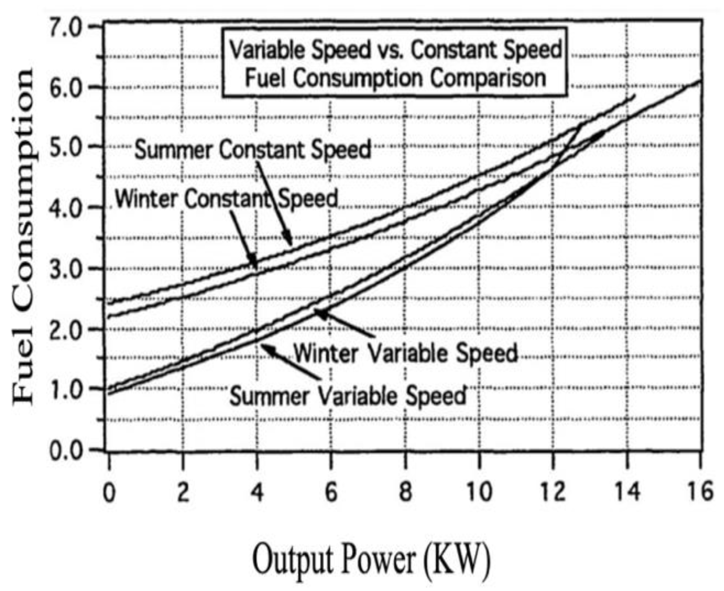
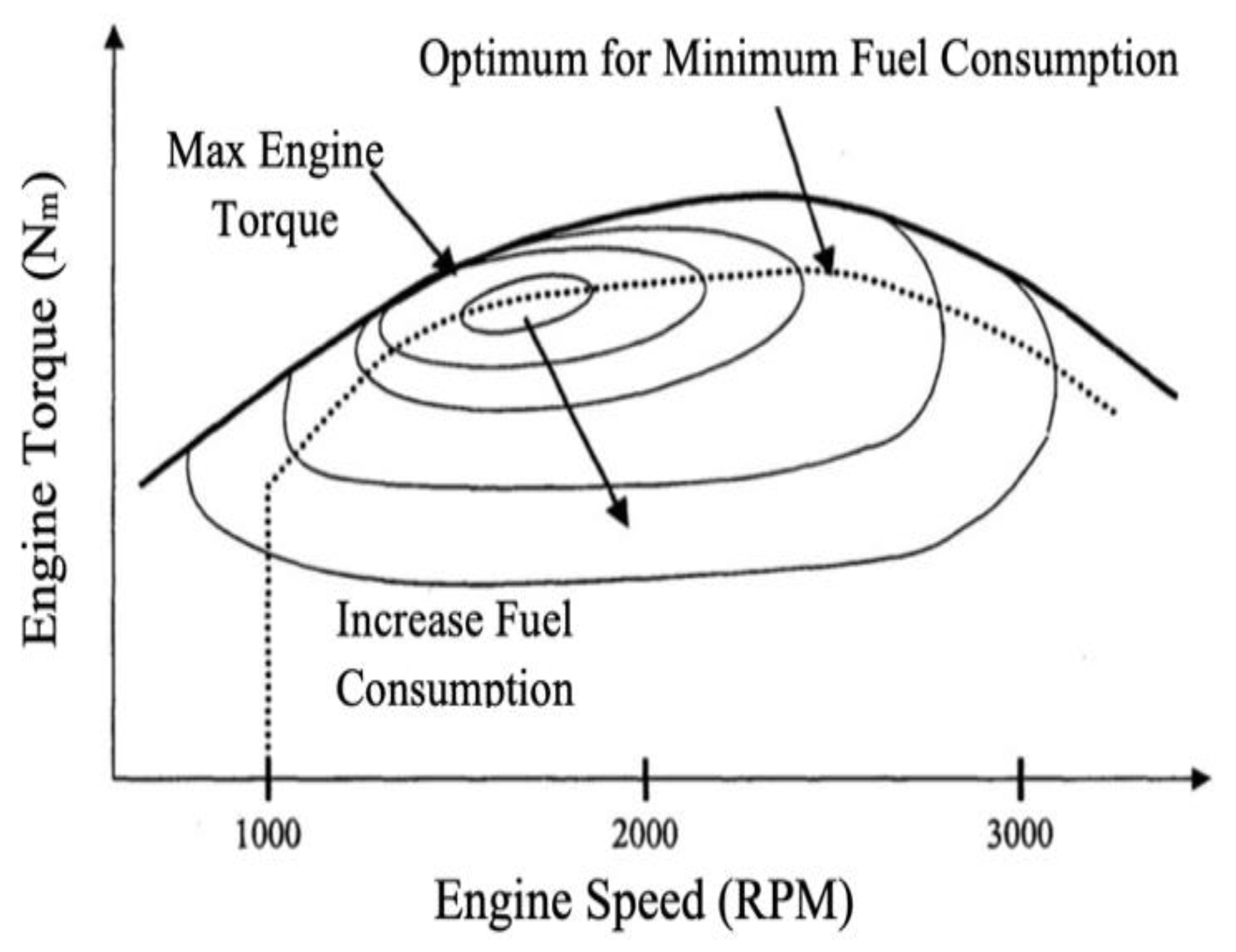
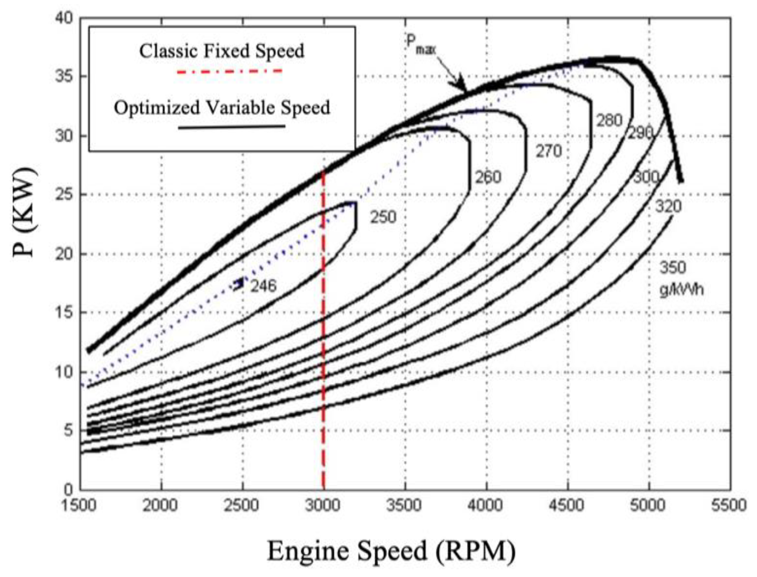
5.2. Fuel Consumption
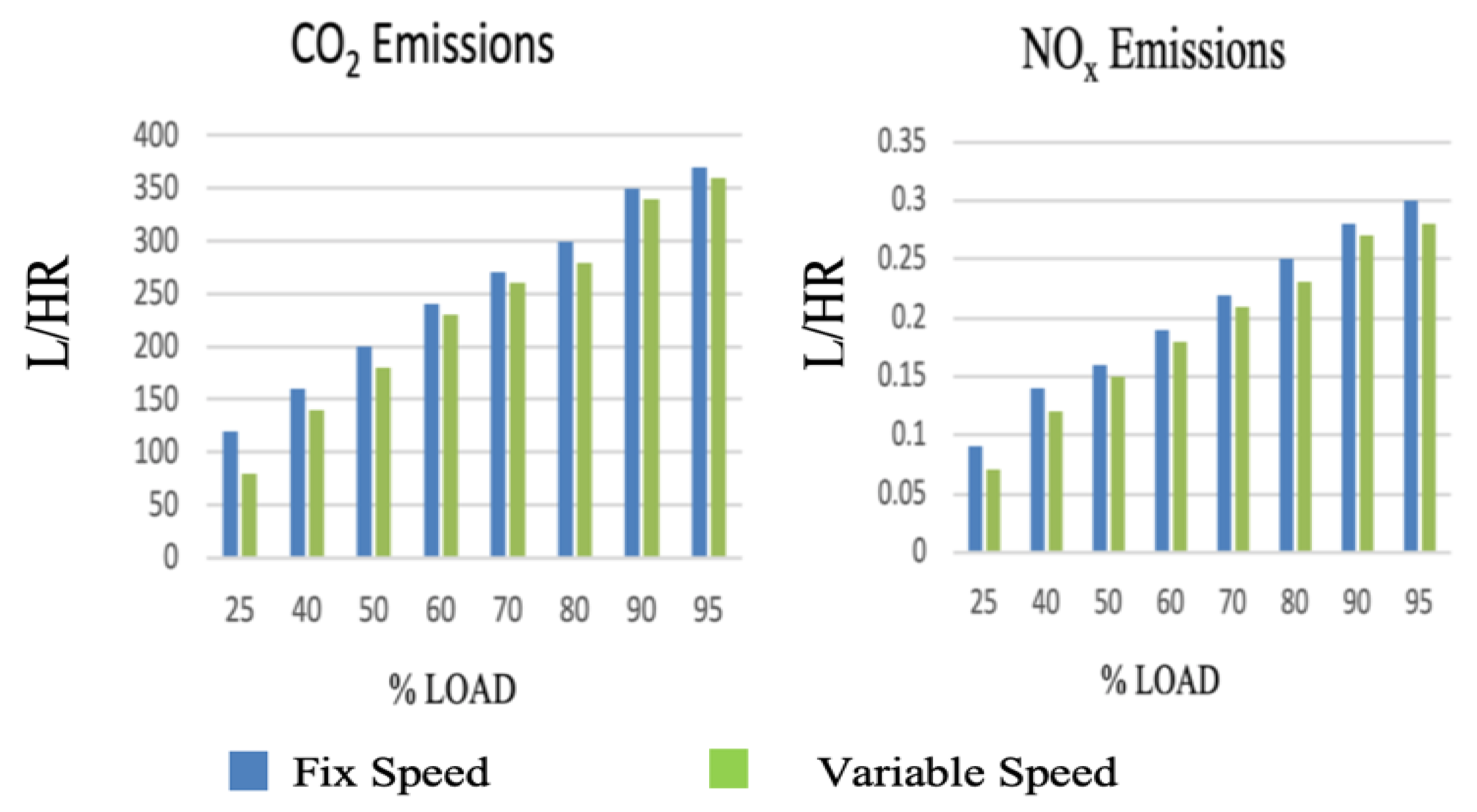
Based on the above explanations, FSDG systems have reduced energy efficiency when operating at low loads. VSDG offers better partial load efficiency by reducing engine speed to an optimized value. These systems can yield a better efficiency by adjusting and programming DE speed with demanded load from the control unit [44]. Figure 6 shows the comparison between FSDG and VSDG of the specific fuel consumption (SFC) as a function of the load and engine speed.
Instead of using VSDG, it is possible to use batteries or other forms of energy storage and stop the FSDG during low load conditions. When this method is used, the engine restarts when the load increases or the battery level is critical [45].
Another method proposed controlling the strength of the stator field and is based on the load variation [32]. The system provides a suitable torque to meet the electrical demand. In fact, by weakening the stator field of the synchronous generators during low electric load, the overall fuel efficiency improves.
An incremental algorithm has been proposed in [46] to track the minimum specific fuel consumption (SFC) operational points of energy conversion for a specific load. This algorithm has been developed to avoid torque peaks during sudden changes if the system speed deviates from the reference speed. The research presents the modeling and speed control of diesel engines and power converters. An optimum operation point is reached during load fluctuations using an efficient increment algorithm of SFC tracking. Moreover, this control method reduces the transient time of the output voltage when considering load torque limitation and speed range.

5.3. GHG Emissions

The effect of GHG emissions is not limited only to climate change and global warming. The World Health Organization named various diseases such as cardiovascular mortality and lung cancer due to air pollution [47]. Based on the research proposed in [48], around 3.2 million people died in 2010 due to hazardous gas emissions from diesel soot and exhaust gases. The most damaging species of diesel exhaust gas are carbon dioxide (CO2) and nitrogen oxides (NOx). Global warming and human health risks are the two main reasons to reduce these emissions [49].
Fuel standards have been tightened in recent years. For example, the sulfur concentration is limited in both gasoline and diesel [35,50,51,52]. Apart from fuel quality, the operation of DE at its ideal speed and cylinder ignition control associated with different load regimes reduce air pollution [53,54]. Figure 7 illustrates the impact of using VSDG instead of FSDG on GHG emissions [43]. Variable speed application permits the engine to provide power following the demanded mechanical load. Therefore, this operation mode has a higher effect on GHG emission reduction during a low load regime.

6. Variable Speed Diesel Generator Technologies

This section presents the characteristics of the most important technologies used for VSDGs, particularly the electrical and mechanical approaches that allow variable speed operation of the DE according to load variation. This study shows that the use of VSDGs increases fuel efficiency and reduces GHG emissions when operating with variable loads, typical of the use of DGs in standby or off-grid applications. A VSDG is particularly suitable in hybrid systems that include highly variable renewable energy sources like wind and solar. These hybrid systems are optimized by introducing storage, especially for isolated communities with no national grid connection. This operational flexibility of VSDGs improves the efficiency of such systems by optimizing both Supply Side Management (SSM) and Demand Side Management (DSM) strategies, which is impossible to be achieved by using the conventional FSDGs [55,56].

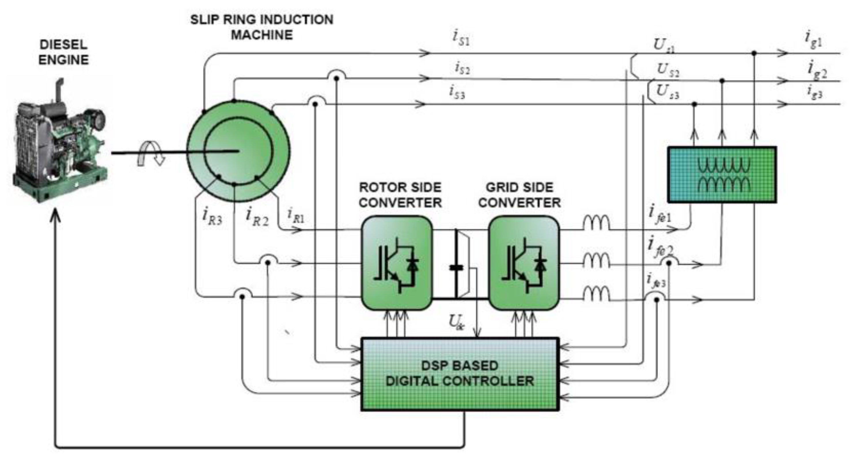
6.1. Diesel-Driven Double-Fed Induction Generator

Generally, power electronics are used for variable speed applications to treat and regulate the output frequency and voltage, respectively. For a DFIG, the frequency and the output voltage are determined only by the power converters. In this topology, the engine speed can change within the power converters’ capacity. The DE speed reduces or increases with electric load variation and within the capacity of power electronics [57]. Figure 8 indicates the schematic diagram of a back-to-back power converter connected to the DFIG.
The power converter size is determined by the power production required, has to maintain power quality, and avoid high system losses. These design constraints increase system security and power quality, respectively. One traditional method to determine power converter capacity is to size it at 30% of the total capacity of the machine-rated power. Consequently, if DFIG operates beyond the recognized speed, the unwanted harmonics may affect output results [58]. In the double-fed arrangement, stator outputs deliver fixed frequency and voltage to the AC load. One popular method to control the stator converter is vector-controlled front-end converters. Normally, the aim of the stator side converter and its vector control method is to regulate the common DC-link. The common DC link is connected between the grid and the supply side converter. On the other side, a three-phase voltage source PWM rotor inverter provides a reliable voltage for rotor windings. The principle of this converter is to control produced voltage by sending feedback signals to the rotor as a reference parameter with the appropriate magnitude and position. Recently, researchers have chosen a sophisticated field orientation control (Sensor or Sensorless) method to control the rotor side converter. This method provides a fast response by evaluating the rotor position. Thus, converters empower the variable applications to operate below or above the required speed [59]. In DFIG applications, it is essential to assess the performance reliability of the system while the operation is under different loads [58].

6.2. Diesel-Driven Wound-Rotor Induction Generator

The VSDGs are widely used in different applications such as backup-supply, grid-connected, and isolated communities. It is necessary to monitor the voltage amplitude and frequency deviation in variable speed applications. However, the output voltage and frequency regulation in grid-connected applications are less critical since they are dictated by the utility grid itself [60]. For stand-alone applications, these parameters are more difficult to maintain within operational constraints with rotor speed variation and electrical load fluctuations [61,62,63]. Among the various methods to control the VSDG output affected by rotor speed variation, only some focused on the effect of load fluctuations in the generation system. The most commonly used generators in DG sets are wound-rotor generators. This type of generator is assembled with a separate exciter system for voltage control and a speed governor for frequency control. The principle of this strategy is to keep frequency and voltage constant by adjusting the current controller parameters equal to the practical machine constants [32,64]. The wound-rotor generator with external excitation control configuration is shown in Figure 9.
This configuration is close to DFIG as the capacitor and load are connected to the stator side, while the rotor side is connected to the inverter. The aim of the stator side capacitor is to repel the output voltage ripples coming from the inverters. Another advantage of using the stator side capacitor is to neutralize the inverter current, and it also provides the magnetizing current for the induction machine. Moreover, system voltage amplitude varies by controlling the stator side capacitor.
A controlled inverter stabilizes the voltage while rotor speed varies with load. Moreover, frequency regulation is achieved by controlling the electric rotor angle (θr) [66]. The inverter and battery also serve for engine start-ups, and the battery charges and discharges depending on the power flow. As long as the engine uses the battery to start, it is essential to control battery SOC conditions during system operation to avoid the subsequent start-up failure [65].

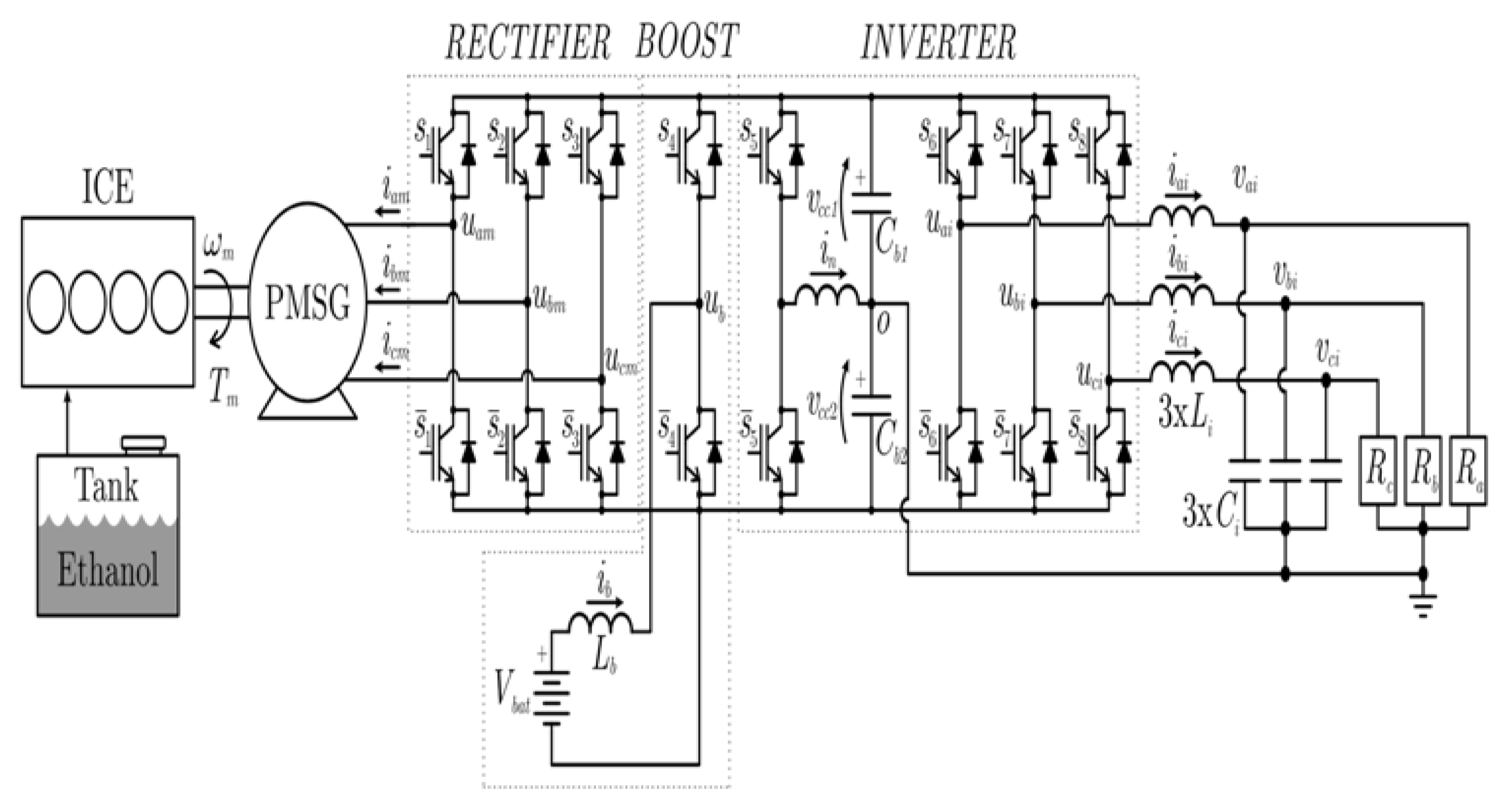
6.3. Diesel-Driven Permanent Magnet Synchronous Generator

A combination of PMSG with power conversion systems improves Genset performance, reduces power system harmonics, and develops a self-excitation control system in variable speed applications. Consequently, different studies focused on integrating variable speed PMSG driven by a DE [67,68]. These projects aim to control system outputs considering variable rotor speed according to the required engine torque to meet maximum efficiency [69]. The solution proposed in [70] uses a fixed Capacitor-Thyristor controlled method to evaluate system stability during load variation. The goal is to maintain the frequency and voltage constant while PMSG is running in a stand-alone microgrid. In study [71], two parallel resonant amplifiers are used to regulate the PMSG output voltage. These amplifiers are designed to repel maximum frequency disturbance using an LC filter. Voltage ripple treatment and third harmonic elimination have been accomplished in this research using a fully digital panel control. In study [72], an adaptive direct-tuning method controls the system DC-link voltage. In parallel with the energy storage systems, power converters improve system flexibility in the case of dynamic performance and voltage control. The authors developed a transfer function control method named closed-form to control the DC-link voltage without being affected by nonlinear loads.
Figure 10 proposes variable speed technology using a controlled battery system. This study used a controlled three-phase PWM converter containing a bidirectional boost converter to charge or discharge the battery based on different load levels. In this DG set, PMSG speed varies based on a stop-start strategy. During low power demand, when the Internal Combustion Engine (ICE) would have operated at low efficiency, the control system stops ICE, and the battery banks energize the grid. Otherwise, the engine starts to support peak load or when the battery SOC decreases under its lower limit [70].

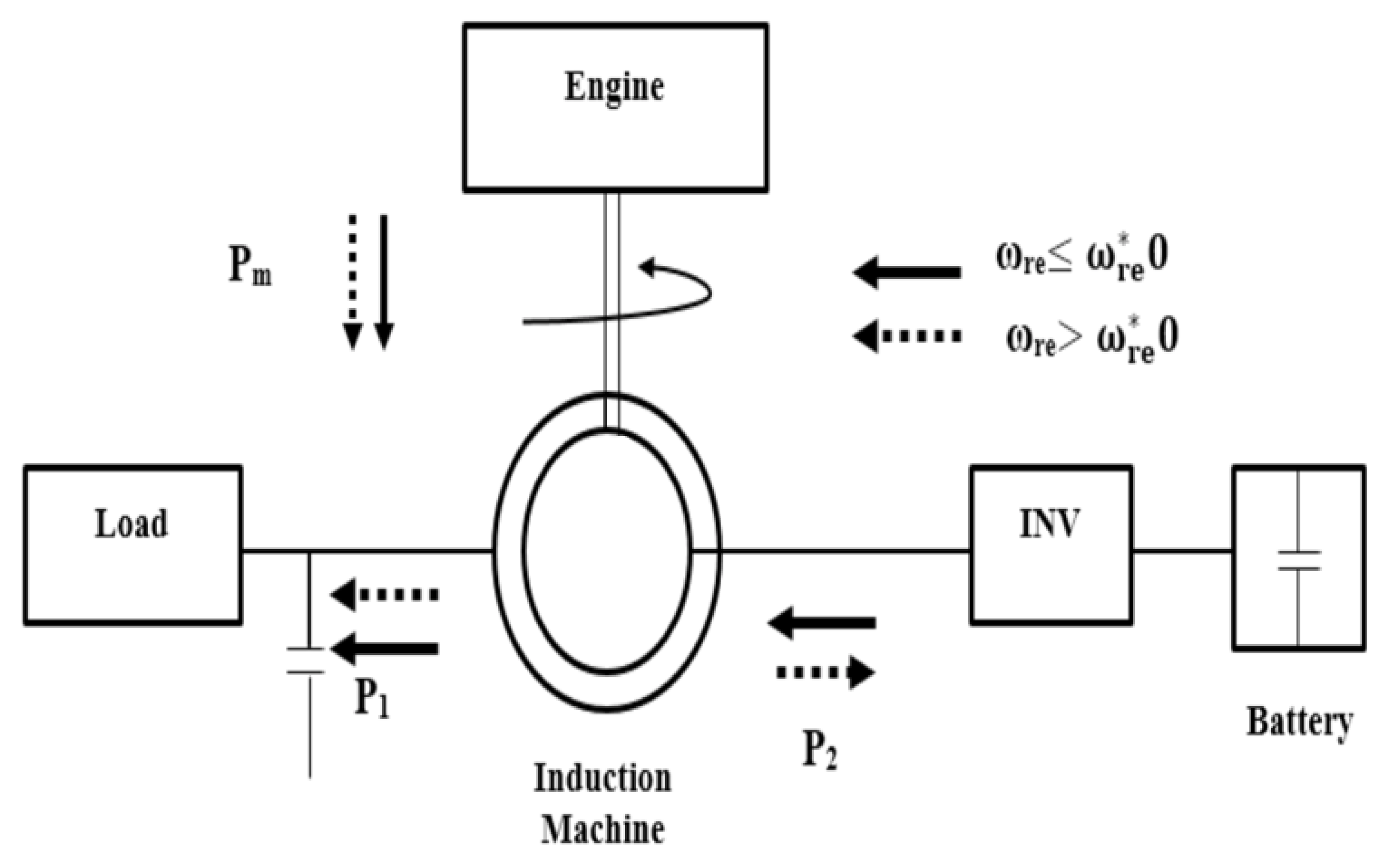
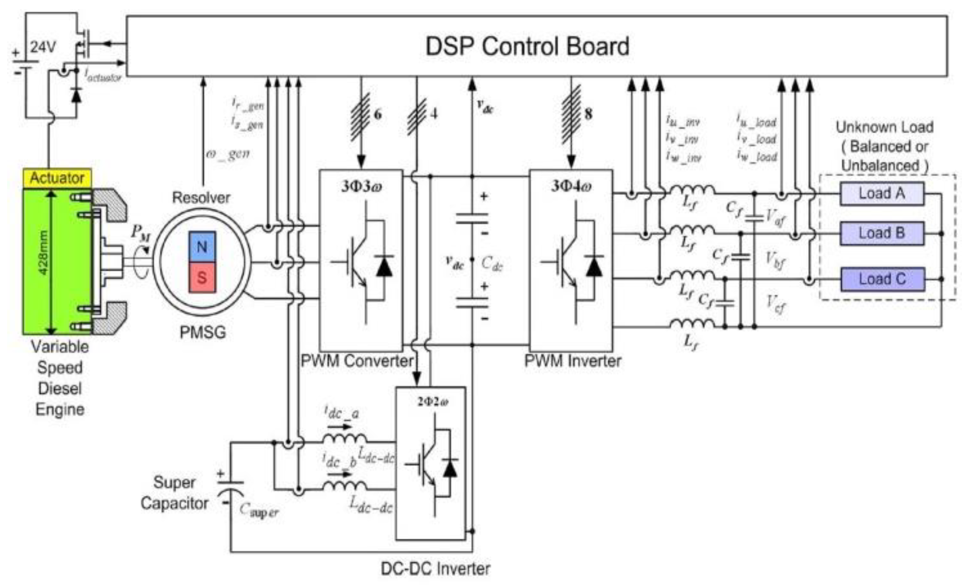
6.4. Engine Generator Application with Super Capacitor

The purpose of using a super-capacitor diesel generator (SCDG) in the power system is to compensate for substantial or sudden load change or to protect the grid as a backup choice in case of a power shortage. One significant advantage of using this solution is to minimize the impact of the load fluctuation on the diesel engine. However, preparing such an arrangement with controlled rectifiers is complicated, and not sufficient enough to produce constant DC voltage during an unexpected load change [73]. The traditional method to meet different electric power demands is to adjust DE fuel hatch using a mechanical governor. However, the sluggish dynamic reaction of the DE produces high harmonic pollution [20,74,75]. In study [76], a sophisticated storage system is integrated with an electric boat DG application to control voltage instability during transient loads. This configuration uses two separate bidirectional DC-DC converters for the super capacitor and the battery storage. The advantage of such a design is to independently control the SC and the battery based on the dynamic response limits. The reason behind using SC with battery storage simultaneously is the limitation of the battery SOC and the time of depletion. Figure 11 illustrates a typical VSDG controlled by SC and power converters. Another method to repel the effect of instant load variation on DG performance is presented in [77], where buck-boost bidirectional DC-DC converters serve as an energy buffer with the SCs. The converters use AC/DC/AC conversion to provide constant frequency and voltage in this design. The authors have suggested two different circuit topologies and compared the results. In both configurations, energy buffers are connected to the DC-DC converter. As for the first connection, the buffer system is connected to the rectifier directly to simplify the system with a simple buck-boost converter. For the second connection, both buffer and inverter are connected using transformers. The role of transformers is to separately meet demand instabilities by isolating the input from output parameters.

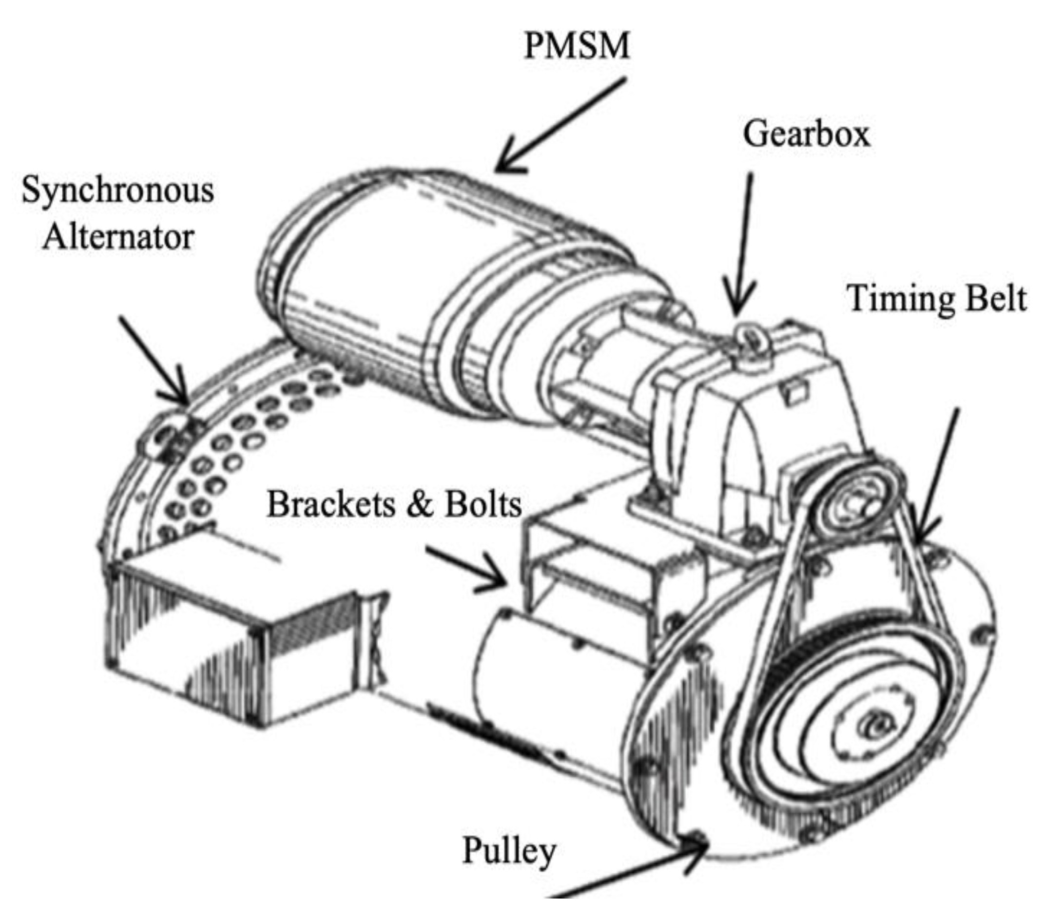
6.5. Rotating-Stator Mode for Diesel Generator

This Rotating-stator technology allows the DE to operate within its optimum speed range while there is a considerable change in the electric load. Unlike other variable speed methods, this technique eliminates the sophisticated power electronics as the speed regulation is obtained through a new generator structure [78]. Figure 12 shows the PMSG generator using a rotating stator. In this technology, the rotor, fixed to the DE crankshaft, can slow down to increase efficiency. The power generator achieves synchronous speed by rotating the stator in the opposite direction to the rotor. Accordingly, the resulting operation of the generator is not limited by the rotor shaft speed anymore. The stator is equipped with several bearings installed on its outer layer. These bearings, located between the stator and the generator casing, allow the stator rotation driven by an external compensator motor. A pulley is fixed at the generator end and connected to the stator [79]. Therefore, by connecting the pulley to the external compensator motor, we can rotate the stator, such as the relative velocity between the stator and the rotor remains constant and synchronized. It is essential to mention that rotor and stator windings and all other components stay the same as conventional [80]. The compensator motor (CM) is mounted on the generator casing and connected to the stator pulley using a timing belt.
The CM rotates the generator’s stator part at different speeds in both directions. This motor works at both 50 and 60 Hz frequency, and the generator itself supplies its energy. The generator’s rotor is coupled with the DE crankshaft and rotates solidary at the same speed. During a low load operation, the DE speed slows to maintain the efficiency, and the compensator motor turns the stator in the opposite direction to maintain a synchronized relative speed [81]. For example, if we consider that according to the load value, the engine speed should be 1545 rpm to have maximum efficiency, then the rotor will also turn at 1545 rpm. The compensator motor drives the stator rotation in the opposite direction to the rotor, at 255 rpm. Therefore, the rotor will rotate at a total relative speed of 1800 rpm to the stator as in a fixed speed generator, without using advanced power control or a complicated excitation system [82].
As a result, we reduce the DE speed at the value corresponding to optimal efficiency and maintain the relative speed between the generator’s rotor and stator.

6.6. Continuously Variable Transmission (CVT)

Continuously Variable Transmission (CVT) is a mechanical solution to adjust the DE speed with the demanded load. It enables the engine to run at different speeds without interfering with the powertrain. The CVT is installed between the DE and the generator to ensure synchronous speed when the DE slows down [83]. The engine crankshaft and the generator’s rotor are coupled using a sophisticated variable gearbox in the CVT technique. This mechanical device increases system resilience by adapting DE speed with a demanded load while providing an ideal speed for the generator itself [84]. Figure 13 indicates the developed Genset schema with a proposed CVT system. The variation of DE speed in this DG depends on CVT flexibility and electric demand.
More precisely, the voltages and frequency are maintained constant if load variations never exceed or fall beyond the CVT limits. This CVT operation saves up to 25% of fuel consumption in grid-connected applications. In addition, the integration of CVT technology with wind-solar applications reduces system complexity and improves DG reaction to load changes.

7. Performance Criteria for DGs

Fixed or variable speed applications are highly preferred as a major source of power production at different grid or off-grid configuration due to several proven advantages such as system robustness, immediate start-up, ease of commissioning, and high-power quality. These applications are fairly suitable in harsh climatic conditions compared to other electrical energy sources. However, there are circumstances when DG performance is significantly affected by ambient conditions, load variation, and other operational characteristics. One purpose of this study is to highlight the critical points and parameters which could have tremendous consequences on the DG performance either in transient or steady-state situations. This following part focuses on a few challenging factors of VSDG use.

7.1. Rate of Adaptation in the Power System

The characteristics and performances of VSDG applications are affected by their role and the integration with the power system.
Grid-connected. Grid-connected DGs are generally used to maintain grid conditions inside operational limits during unpredictable faults. The central grid stability improves with the availability of multiple, distributed, reliable, and predictable DG, especially with the increased percentage of variable renewable energy sources connected to the grid. Therefore, a power shut down has fewer negative consequences on the consumers when local sub-grids are powered with DG energy. As electric grid connections are configured like a web, smaller areas are affected by a lack of electricity during power shortage [85,86]. Starting, stopping, and synchronization of a typical VSDG system in a grid-connected application is simple and fast because the grid parameters never rely on a specific source of energy. One important advantage of VSDG when connected to the central grid is the capacity to synchronize DG speed to prevent alternator damage [87]. In conclusion, the most important role played by grid-connected GDs is to maintain grid parameters within acceptable limits during unpredictable faults [88,89].
Stand-alone DG. Isolated electrical grids are more sensitive to electric loads’ fluctuation and engine speed variation. Therefore, for these applications, the objective is to minimize the cost of energy and control the system, such as to maintain output parameters within acceptable limits [90,91]. Managing such a system is complicated and requires a comprehensive study on the load characteristics, and the power switches limits. In study [92], the VSDG is connected to the DC bus using power converters. The rotor speed follows the power demand from the DC bus side of the grid. The load power variation and the state of charge (SOC) of the batteries determine the control of different system parameters.

7.2. Diesel Capacity and Available Power

Design choices (air-cooled or water-cooled) and sizing of every DG application depend on the required power, the operating, and ambient conditions. The electric load and the instantaneous production from renewable sources are two momentous parameters that have major impacts on the DG performance [93]. In study [94], the power flow for a hybrid, stand-alone electrical grid was monitored for two years. As a result, a model based on field measurements was developed to increase efficiency and minimize fuel consumption. The main parameters influencing the design and sizing of the diesel generator for the hybrid system are:
  • Annual Load Fluctuation (daily and seasonal graph);
  • Annual Load Growth;
  • Incorporation of Diesel Constraint.
Typical stand-alone electrical grids in remote communities are characterized by high load fluctuations with a peak load of 4 to 5 times higher than the average load. The traditional method defines the DG characteristics based on the peak load, safety margins, and future load growth prediction. However, this approach is associated with low system efficiency and high maintenance fees due to an oversized diesel plant [95,96]. One way to avoid running a single, large diesel generator is to install multiple DGs with lower capacity and support the load using diesel cycling and dispatch strategy [94].

7.3. Efficiency

Load characteristics, fuel quality, ambient condition, engine design and capacity, humidity, and operation hours are the main parameters that affect DG’s efficiency. For instance, low electric load or high load fluctuation result in diesel engine idling time. Subsequently, the operation of the diesel engine during idling time impairs DE fuel consumption efficiency and power quality. Several standards and guidelines define how the manufacturers measure DG efficiency at the production line [97]. As a result, they define the operational limits that DGs should meet to supply an electric grid [98,99]. Based on different conditions and criteria, several studies estimated how to improve DG performances. For example, the German association, VDEW-profile, has introduced different DE duty cycles based on measured value and the real demand [100]. One practical method to increase efficiency is to calculate the engine fuel consumption based on a typical load profile using computer simulations. This method quickly identifies the errors in the simulation by comparing the results with the ones available from experimental tests. Accordingly, the analysis of the final results based on the different load characteristics helps the engine control system to determine and adjust the optimal required rotational speed based on the load [101].
The energy efficiency of a DG is a combination of efficiencies of its two main components: the DE and the electric alternator. The overall Genset efficiency over a given period, i.e., in terms of energy, is defined by [102]:
Genset   Efficiency   ( % ) = Alternator   Output   Energy k W h   Caloric   Energy   of   Burned   Fuel k W h × 100
In every single Genset application, several common and specific factors affect system efficiency. For instance, the penetration of an engine generator set in a hybrid stand-alone application may affect efficiency based on operation hours or the number of start-stops during a day. Moreover, a precise evaluation of DG sizing for a given application also may augment system efficiency [103,104]. Genset system consists of an engine, and an electric generator could have a separate efficiency of 30% to 60% and 85% to 95%, respectively. The combination of both, while operating as a main source of energy, vary from 30% to 55% [105,106]. It is essential to mention that DG set efficiency may change during its operation according to several ambient conditions such as engine temperature or load condition.

7.4. Durability

Durability or endurance is an important factor that can significantly affect the feasibility, equipment availability, and maintenance fees under different operation conditions. This parameter is particularly critical for the engine part of the DG set. The durability of the engine is the probability that its structural material will withstand several charges that may or may not be time-dependent, such as fatigue, wear, corrosion, thermal equilibrium, mechanical stresses, chemical mechanisms, etc. [107].
Figure 14 indicates the stress and strength interference diagram that will characterize the durability and reliability of the Genset. In this graph, the stress represents the load, and the strength means the structural hardware capability. A durability test for engine components is conducted to check the threshold tolerance point of the different parts of the engine. This test applies sufficient mechanical or thermal stress based on engine-specific operation conditions [108]. Durability is also vital for the electric generator, but mechanical failures are less frequent due to developed power switches and advanced monitoring techniques. However, the long operation of the generator under a peak load regime or unpredictable overload condition may increase the temperature of the windings and impair system isolation.

7.5. GENSET Criteria

One method to provide secure power quality for the end-user and match the same parameters of different components is to define proper specifications for the power system. For example, in ISO 8528-1 standard for rating and performance of diesel generator, different rules and specifications are defined for generator’s alternating current, Reciprocating Internal Combustion (RIC) engine, GHG emission, fuel type, and auxiliary equipment.
The ISO manual specified four different classifications to help the manufacturers and consumers have a common basis and to better understand system limitations [109,110]:
  • Emergency Standby Power;
  • Prime Rated Power;
  • Limited-Time Power;
  • Continuous Operating Power.
Moreover, in each generator set installation, several factors are dictated by the ISO standards to be followed during production, such as maximum and minimum load demand, harmonics, power factors, and fuel quality [111]. These instructions make it possible to provide high-quality and efficient power on the demand side, and simultaneously improve customer loyalty and retention.

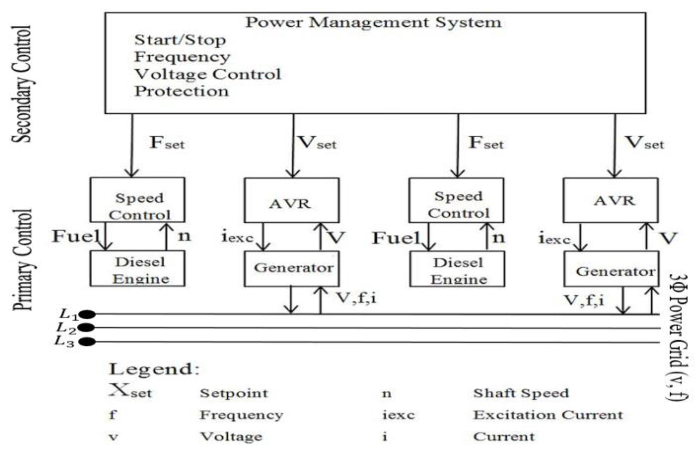
7.6. Monitoring and Control System

Each autonomous DG system must monitor its production and analyze the system’s state by receiving high-precision feedback during the various conditions mentioned above. Stand-alone grids in isolated communities require a sophisticated control method to regulate the system’s frequency and voltage. At the same time, grid-connected applications monitor the power system to be more flexible and secure in a power outage. Speed estimation and adjustment are essential factors in variable speed control projects. One way to evaluate rotor position and speed is to use mechanical devices such as camshaft sensors or mathematical prediction of rotor position without sensors [112]. Most of these methods used the same principle (d-q projection) to control the output power. For example, in study [113], an indirect vectorial approach controls a hybrid wind-diesel system. The author used d-q reference frames to model the generator.
This project aims to couple the speed of the diesel engine with load variation and adjusts the electrical torque of the wind-powered generators to increase production efficiency. Figure 15 shows a typical strategy for monitoring and controlling the generator’s power to produce a fixed frequency. In this method, both speed and voltage are maintained at a specific set point to keep the system output within the standard acceptable range.
The proposed energy management system provides an automatic start and stop function to protect the online system from overloads during load fluctuations. Another method is proposed in [115] to compensate for the slow and nonlinear characteristics of the diesel engine. The Sliding Mode Control (SMC) method for variable speed operation controls the system output using mathematical models. An 11% fuel consumption reduction is achieved by designing a single sliding surface with a command law to track the oscillations appearing in the system based on the reference speed. In this technique, the command law is applied to the SMC controller to obtain a fast reference tracking and update the reference speed reference with the load variation. The author mentions that the SMC method monitors the system performance with zero steady-state error.

7.7. Fuel Cost

Several parameters and phenomena affecting DG performances have been discussed above. Besides, ambient temperature, the power rating of the Genset, and fuel quality are essential factors that will affect fuel consumption. There is a relationship between fuel consumption and electricity production [116], and the fuel cost is calculated as [117]:
F C i = a i P g e n 2 ( i , t ) + b i P g e n ( i , t ) + C i ( $ / h )
where a i , b i and c i are the cost coefficients of the diesel generator, F C i is fuel cost, and P g e n is the power produced by the DG.

7.8. Output Power

DG production is within the maximum and minimum capacity limits released by the manufacturers. The rotational speed of the rotor, load impedance, and rotor excitation system affect the generator output. The power generated by the DG is defined as [117,118]:
P g e n = P n × N g e n × η g e n
where N g e n is the number of generators, P g e n and P n are the alternator generated power and nominal power in kW, respectively, and η g e n is the overall efficiency of the DG system.

7.9. Other Aspects

Diesel generators are quick to start, durable in long operation hours, and operate in various climate conditions. These characteristics made DGs suitable to power multiple applications such as grid-connected, stand-alone, and emergency backup [119]. Moreover, the integration of DGs with renewable energies in distributed generation applications can highly increase system efficiency. Below are several aspects that need to be considered in every diesel generator set:
  • Timely repair or upgrade components;
  • Scheduled water and oil check;
  • Periodical service (oil-changing fuel, oil and air filter changing);
  • Battery inspection;
  • Generator inspection and connections cleaning;
  • Genset control panel and indicators;
  • Biweekly engine start (backup applications) [120];
  • Verify exhaust and input air.

8. Comparison of Different Variable Speed Generators’ Techniques

To compare different technologies discussed in Section 6, four different groups are selected based on the literature’s applications where DGs typically face critical challenges (Table 1). The term “Performance Index” is also created based on a list of criteria proposed in Section 7, such as durability, efficiency, power control, etc.
Figure 16 indicates the comprehensive comparison of VSDGs for the four groups of applications. It is important to mention that the accurate performance estimation of a specific diesel generator application depends on the typical load map and manufacturer’s product.
Therefore, the data represented in Section 8 belong to the typical systems and may not cover all available products [121]. The performance index demonstrates the applicability of VSDGs based on selected criteria. From the bar chart (Figure 16), SCDG has shown a rapid reaction in case of a sudden huge load change. Supercapacitor connected with the battery storage system compensates required power for the demand side.
For grid-connected applications, PMSG and WRIG have shown high fuel-saving and low operation cost compared to applications where there is no substantial sudden load change. These solutions can solve technical issues such as frequency regulation or power system stability.
The following subsections compare the VSDG techniques in different aspects for grid-connected or/and stand-alone applications.

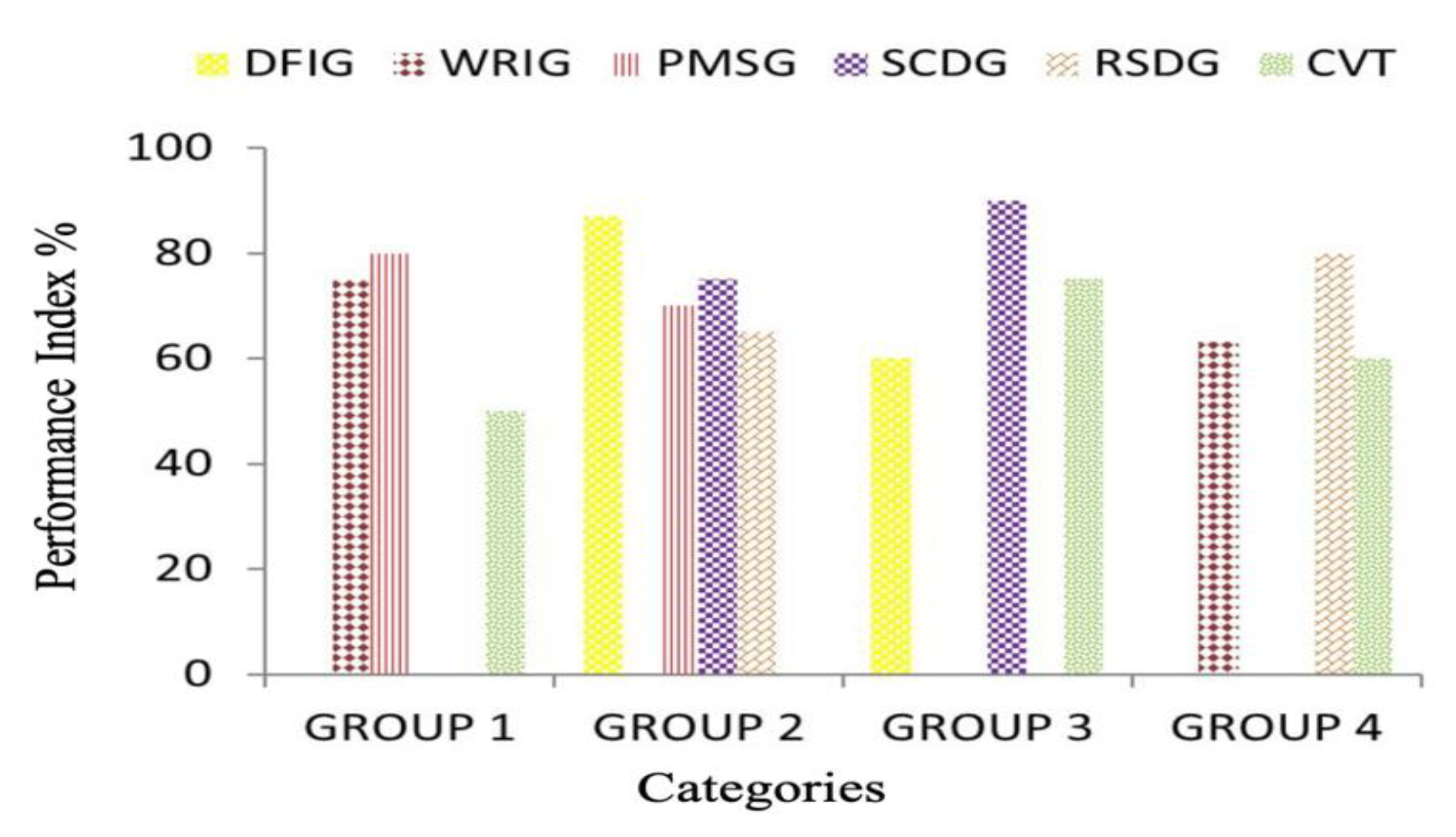
8.1. Performance Comparison of VSDG into Power System

Table 2 proposes three important factors that may be affected when using a typical VSDG in a power system. Results are achieved using different references mentioned in this study. Since fuel optimization and frequency regulation technologies are well discussed in Section 5 and Section 6, this part focuses more on the power quality factor. It is important to classify power quality disturbances to understand the electromagnetic phenomena and to regulate the measured results [122].
Most common power quality problems occur in the form of voltage swell, voltage spike, harmonic distortion, voltage unbalance, voltage fluctuations, etc. [123,124,125,126]. Uncertain rotor speed, imbalanced loads’ connection, sophisticated power converters, and longtime grid fault appear in low power quality or high harmonic distortion. More precisely, poor power quality happens when the speed of the generation system fluctuates due to the discussed reasons (renewable sources are not constant and conventional sources need to optimize the consumption during low electric load) or when there is an electric oscillation from the demand side [127,128].

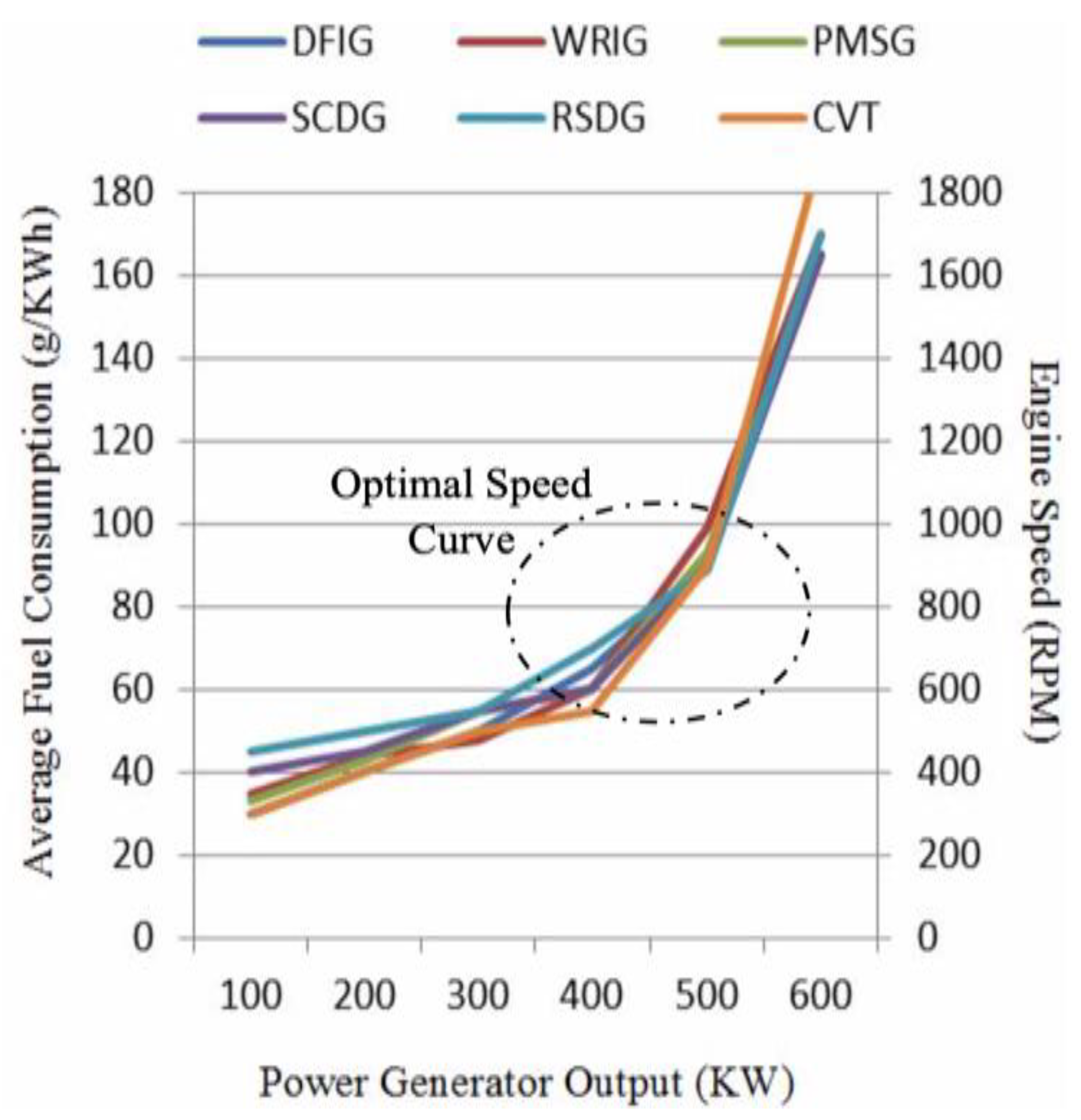
8.2. Comparison of Fuel-Saving

The main reason to run DE at variable speed conditions is to optimize engine fuel consumption. Accordingly, severe competition between manufacturers dedicates highly efficient Genset to the industrial and residential sectors. These Gensets are developed with different techniques mentioned above, while most of them have the same principle (electric converter) but with different control strategies. To obtain the minimum fuel consumption rate in every variable speed method, the reference speed should be adjusted based on the load fluctuation. The reason behind this strategy is that engine reaction adapts more rapidly with a recognized load map [115]. Nonlinear speed control methods proposed in different literature improve an engine’s fuel profile by considering the engine productivity and load capacity. Figure 17 shows the average engine fuel consumption of different variable speed techniques in both grid-connected and isolated communities. The optimal speed curve demonstrated in Figure 17 is a preferable area where the engine operates efficiently. Graphs below are produced based on the average of different literature results and may not demonstrate the exact behavior of a specific application.

9. Overall Comparisons of VSDG

In the previous sections, we discussed several VSDG technologies and operational parameters for different applications. Each VSDG technique has advantages and inconveniences that make it better for a specific application and not necessarily for all of them. This section evaluates how each VSDG solution is suitable for four different operation conditions: grid-connected application, island-mode operation with low load, fast load oscillation, and integration in a hybrid system.

9.1. Grid-Connected Applications (Regulate Frequency Variation or to Meet Peak Leveling Period)

In grid-connected communities with slight load fluctuation or long periods of low load, CVT and RSDG are more efficient solutions due to low initial cost and simple control systems [81,83]. However, eliminating a power converter in RSDG made the system more efficient but in long-term projects. This technology can reduce fuel consumption by 20 to 50%, depending on the load level. In addition, RSDG proved more efficient during low loads. In contrast, CVT can save fuel during load variation, but its speed variation cannot cover a wide range. In addition, these technologies may serve in grid-connected applications for frequency regulation and stability augmentation.
As for power quality, both technologies are vulnerable to unpredictable and fast load variations. The RSDG follows load variation and tries to adapt to it using a small control drive. This strategy may impair power quality for a few seconds. By design, the CVT technology adapts rapidly to load variation, but attenuation of different speeds may produce harmonic pollution.

9.2. Islanded Mode Operation with Long Low Load Operation

In the case of islanding with limited access to the national grid, an important parameter to be controlled is the apparent power.
Variable speed PMSG and DFIG may not be the best option for every application, but they are able to adapt fairly to both grid-connected and isolated operations. Low maintenance fees and high fuel-saving made these systems popular, among other methods. These techniques are better adapted for ramp-up operations. However, power converters are expensive and have limited capacity. The overall speed of the generation systems cannot move beyond or under converter capacity. Several studies are showing significant achievements by integrating variable engine-driven PMSG or DFIG with renewable technologies in distributed generation applications. The majority have chosen different vector control strategies such as FOC or DTC using sensors or sensor-less methods [131,132].
These methods are well developed to treat rotor or stator parameters and can be used efficiently in hybrid stand-alone or isolated applications (mines, telecommunication towers, etc.). The DFIG is easier to integrate with renewable energies as the power converter scheme uses a DC-link for SSC and RSC. This feature enables DFIG to operate in both sub and super synchronous speed. However, this arrangement increases control complexity and, in some cases, produces harmonic pollution in the power grid [133,134].
Turning to PMSG driven by DE, brushless construction is an ideal AC machine for a DG set. However, this application needs energy storage to avoid low power quality in different unbalanced load conditions. For instance, the integration of PMSG with BESS provides active power conditioning and has shown its effectiveness in delivering standard power along with power factor correction and voltage regulation [10,135]. A critical role of BESS is to save surplus active energy, which is produced during low electric load and released during unbalanced load conditions.

9.3. Fast Load Oscillation

In a typical power system, a large load fluctuation requires a sophisticated compensator storage system to avoid harmonic pollution. Therefore, a combination of power storage systems with variable speed power production, like in the SCDG, will cope with these challenges. Supercapacitors can provide more power density, farads, and life cycles. However, system control and operation are more complicated as the storage system needs to adapt to the system uncertainties [136]. It is essential to control the supercapacitor discharge process and improve its charging procedure. Additionally, the accurate sizing and control of the supercapacitor in a typical power system are necessary to avoid capacitor failure and other serious challenges. Due to the mentioned parameters and based on a typical load, the system cost is more expensive compared to other VSDG techniques, including high maintenance or renovation fees. Overall, SCDG has shown reliable performance when the storage system compensates for voltage fluctuations and the power converter regulates output frequency. One advantage of using supercapacitors is supplying excessive power for a few seconds, even out of engine capacity.

9.4. Integration in a Hybrid System (Penetration of VSDG in Renewable Energy Applications)

WRIG is more efficient in grid-connected applications or combined with other renewable energy sources as its dynamic response is slow and cannot support sudden large load changes [137]. However, WRIG can reduce fuel consumption and pollution in standby or autonomous operation of large DG, up to 20–40 MW. Moreover, below 1.5–2 MW/unit, the use of WRIG is not justified in terms of cost versus performance when compared with full-power rating converter synchronous or cage-rotor induction generator systems [138].
On the other hand, this method needs an extra mechanical device (flywheel) to avoid harmful effects on the rotor shaft in the case of a grid power shortage. Since the excitation system is controlled directly by the limited capacity inverter, a sudden and huge change may ruin rotor winding [60]. However, WRIG is less expensive than other techniques since its structure is simple and needs less maintenance. In addition, a power converter installed on the stator side of the machine improves the power quality. Therefore, the converter capacitors can provide magnetizing current for the machine itself. This configuration reduces the ripple coming from the power grid.

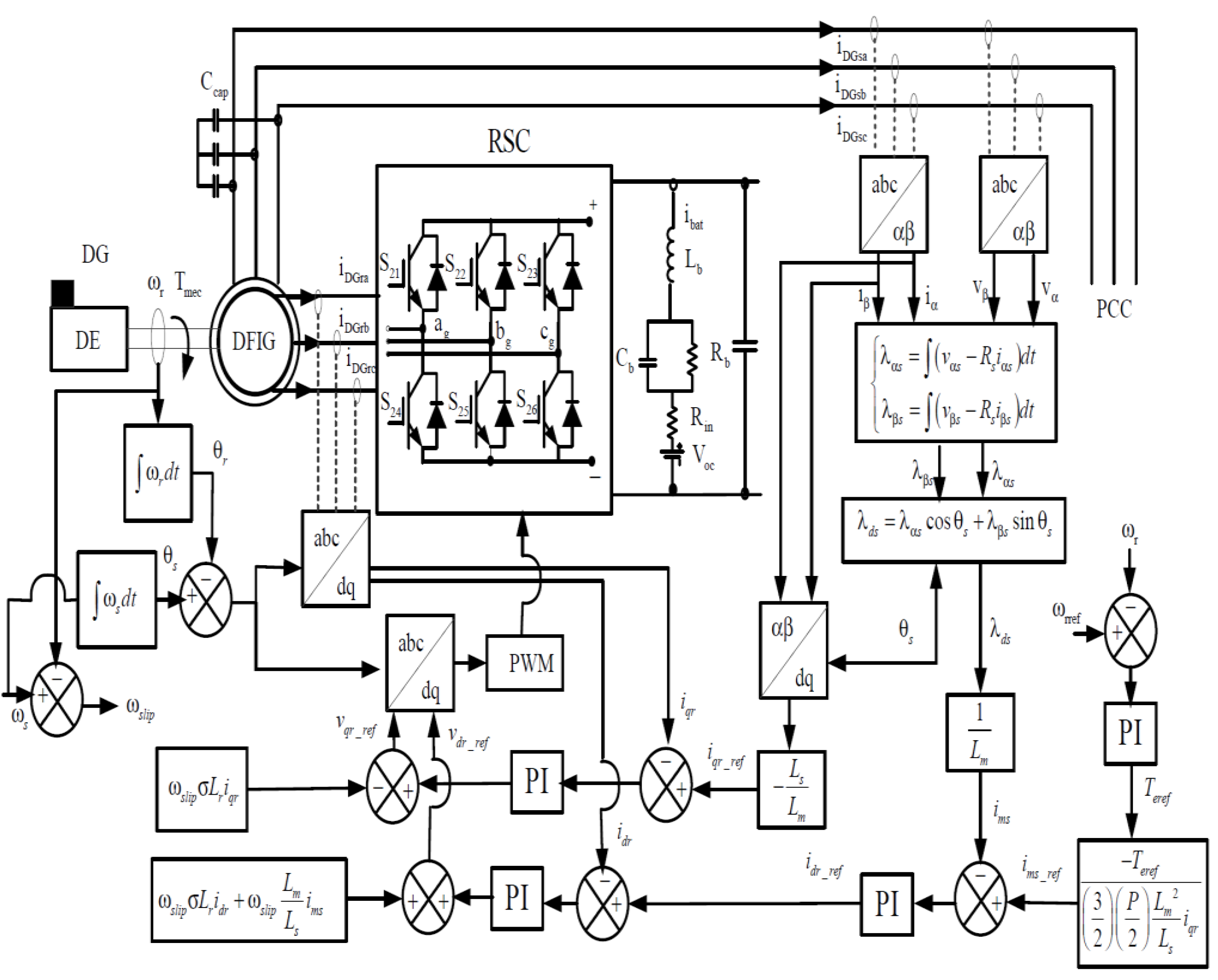
10. Case Study of DE-Driven Variable Speed Doubly-Fed Induction Generator

Different power converter interfaces have been suggested to increase the efficiency of diesel engine-driven DFIG and control electric generator output while the power system experiences abnormal conditions. Back-to-back power converters are divided into the rotor side converter (RSC) and stator side converter (SSC). These converters update generator parameters instantly by using the vector control method. Rectifiers, inverters, and choppers are the recognized controlled power switches to achieve ideal voltage and frequency at the point of common coupling (PCC). Moreover, in isolated communities with backup storage systems, these components can accurately integrate the storage system with PCC [137]. However, different power switches may create losses, impair power quality, and increase capacitor breakdown risk. Diesel generators use an AVR system to control the rotor magnetic field. This electric device maintains the output voltage at a reference value during steady-state operation. However, the AVR system is not adequate to maintain the output voltage constant during the transient behavior of the power grid. Consequently, an additional controller package is installed in a Genset application to control the system during unpredictable circumstances. Two types of back-to-back power converter topologies for doubly-fed variable speed induction generators are proposed as follows:

10.1. Control of the Rotor Side Converter (RSC)

The rotor side converter adapts phase voltage into the rotor circuit and regulates produced power within the standard grid codes while DE speed slows down in a low load regime [139]. In addition, different applicable control methods are projected with RSC arrangement to tackle several challenges of VSDG in the power system.
One purpose of RSC is to treat generated active power while the generator is operating at super or sub synchronous mode. The principal structure of RSC is simply matched with the generator model presented in dq-projection. Accordingly, the active and reactive power of the generator can be presented by the rotor’s d and q axis, respectively. Consequently, the generator excitation current is an important parameter RSC can provide and adjust [140]. The indirect stator flux-oriented control algorithm is a typical control method to adapt with RSC and regulate the produced electric energy through stator flux [141,142,143]. Figure 18 indicates a popular control technique for a DFIG using a vector control strategy. In this method, dq-transformation has been used to separate the active and reactive current. The q-axis current represents DFIG torque and controls the active power, while d-axis characterizes machine flux to control reactive power [144].

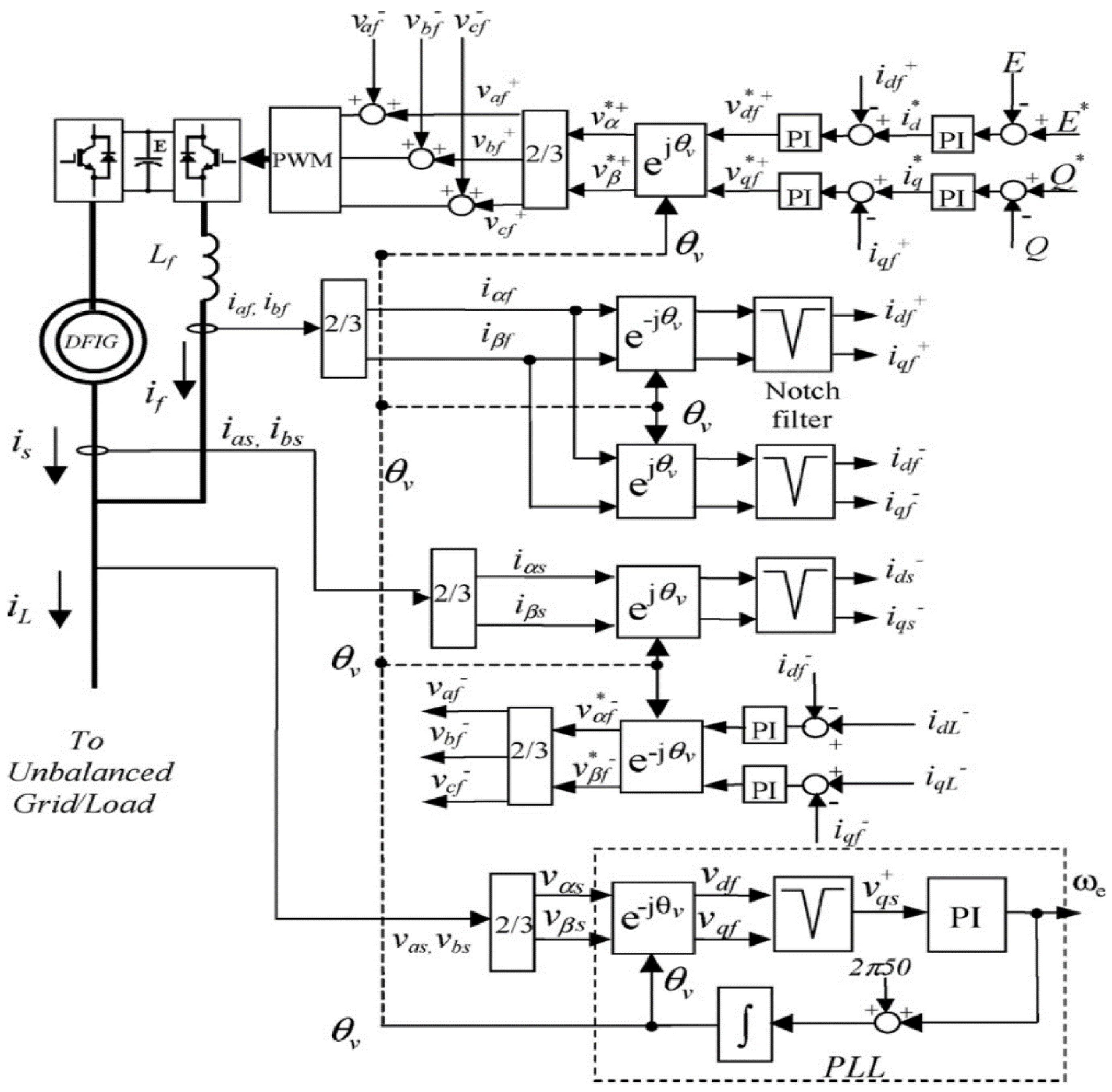
10.2. Control of the Stator Side Converter

Stator (grid) side converter (SSC) is largely employed to control the available power of DC-link considering demand side slip magnitude or to supply electric load by controlling reactive power [145,146]. Figure 19 indicates a negative sequence stator voltage control algorithm using SSC arrangement. Several studies have targeted SSC structure in their piece of works to develop a control method for a specific application.
In study [146], symmetrical components and a vector control scheme are applied to the SCC. This article has successfully used SSC as an active shunt filter to control unbalanced load conditions and compensate reactive power for the demand side. Two RSC and SSC power inverters have been used in [147] as control drives. The role of SSC is to compensate for the voltage and current uncertainties by applying regulated current into the grid. This vector controller has used negative sequence currents to compensate the stator voltage connecting to the unbalanced load. The control algorithm has used notch filters and a PI controller to adjust the orientation of the reference frame. The author highly granted the proposed technique as a reliable application in different grid-connected or stand-alone communities using fixed or variable speed production.

11. Results and Discussion

Several DE-driven variable speed power generators are studied in detail. Critical criteria and practical parameters of these applications are discussed. The design of every control algorithm is achieved based on different tasks such as voltage and frequency regulation, harmonic minimization, engine optimum speed, GHG emission reduction, etc. The result of the proposed designs is up to 40 percent fuel-saving during different application conditions. However, the majority of the scenarios have an inefficient performance during huge electric load oscillation. In terms of hybridization, integration of VSDG with renewable energy technologies in stand-alone application severely increases engine efficiency, improves system stability, and optimizes energy cost dramatically.

12. Conclusions

Grid power quality, system stability, and production efficiency are three major challenges of every modern power system. Turning to a future energy production perspective, modern DEs operating to meet emergency conditions or, in worse cases, regulating system parameters (voltage, frequency). High penetration of renewable energy sources into hybrid power systems keeps modern DG on-hold for particular operations such as backup or SSM. In such a system, synchronizing variable speed techniques into an electric power grid would be a new challenge. This strategy especially helps the conventional power sources reduce their fuel consumption and minimize additional expenses. Among proposed production systems, some techniques are able to save more fuel and produce more reliable outputs. However, these methods are not suitable for all applications, specifically with sudden and large load oscillations. On the other hand, some techniques demonstrate reliable performance during load variation even in remote areas but not too efficiently for small communities as they need a high initial investment.

Author Contributions

Conceptualization, M.M.; methodology, M.M.; validation, M.M.; writing paper, M.M.; refining the manuscript, M.R. and A.I. All authors have read and agreed to the published version of the manuscript.

Funding

This research received no external funding.

Institutional Review Board Statement

Not applicable.

Informed Consent Statement

Not applicable.

Data Availability Statement

Not applicable.

Conflicts of Interest

The authors declare that they have no conflict of interest to this work. We declare that we do not have any commercial or associative interests that represent a conflict of interest in connection with the work submitted.

Nomenclature

Acronyms
ACAlternating Current
AVRAutomatic Voltage Regulator
BSFCBrake-Specific Fuel Consumption
BTUBritish Thermal Unit
CMCompensator Motor
COCarbon Monoxide
CVTContinuously Variable Transmission
DCDirect Current
DEDiesel Engine
DFIGDoubly-Fed Induction Generator
DGDiesel Generator, the combination of a Diesel Engine with a Power Generator
DQDirect Quadrature
DSMDemand Side Management
DTCDirect Torque Control
FOCField Oriented Control
FSDGFixed Speed Diesel Generator
GCGrid-Connected
GENSETDiesel Generator, the combination of a Diesel Engine with a Power Generator
GHGGreenhouse Gases
ICEInternal Combustion Engine
ISOInternational Organization for Standardization
NOXNitrogen Oxides
O&M Operation and Maintenance
OGOff-Grid
PCCPoint of Common Coupling
PMSGPermanent Magnet Synchronous Generator
PWMPulse Width Modulation
RICReciprocating Internal Combustion
RPMRevolutions Per Minute
RSCRotor Side Converter
RSDGRotating-Stator Diesel Generator
SCSuper Capacitor
SCDGSuper-Capacitor Diesel Generator
SFCSpecific Fuel Consumption
SMCSliding Mode Control
SOCState of Charge
SSCStator Side Converter
SSMSupply Side Management
THDTotal Harmonic Distortion
VSDGVariable Speed Diesel Generator
WRIGWound-Rotor Induction Generator

References

  1. Chen, Z.; Hu, Y. A hybrid generation system using variable speed wind turbines and diesel units. In Proceedings of the IECON’03, 29th Annual Conference of the IEEE Industrial Electronics Society (IEEE Cat. No.03CH37468), Roanoke, VA, USA, 2–6 November 2003; Volume 3, pp. 2729–2734. [Google Scholar]
  2. Fayad, M.A.; Al-Salihi, H.A.; Dhahad, H.A.; Mohammed, F.M.; Al-Ogidi, B.R. Effect of post-injection and alternative fuels on combustion, emissions and soot nanoparticles characteristics in a common-rail direct injection diesel engine. Energy Sources Part A: Recover. Util. Environ. Eff. 2021, 3, 1–15. [Google Scholar] [CrossRef]
  3. Fayad, M.A.; Dhahad, H.A. Effects of adding aluminum oxide nanoparticles to butanol-diesel blends on performance, particulate matter, and emission characteristics of diesel engine. Fuel 2021, 286, 119363. [Google Scholar] [CrossRef]
  4. Mohankumar, S.; Senthilkumar, P. Particulate matter formation and its control methodologies for diesel engine: A comprehensive review. Renew. Sustain. Energy Rev. 2017, 80, 1227–1238. [Google Scholar] [CrossRef]
  5. Al-suod, M.; Alexander, U.; Olga, D. Optimization of the structure of diesel-generator units of ship power system. Int. J. Adv. Comput. Res. 2015, 5, 2249–7277. [Google Scholar]
  6. Khatib, T.; Mohamed, A.; Sopian, K.; Mahmoud, M. Optimal Sizing of the Energy Sources in Hybrid PV/Diesel Systems: A Case Study for Malaysia. Int. J. Green Energy 2013, 10, 41–52. [Google Scholar] [CrossRef]
  7. Rahman, S.A.; Masjuki, H.; Kalam, M.; Abedin, M.; Sanjid, A.; Imtenan, S. Effect of idling on fuel consumption and emissions of a diesel engine fueled by Jatropha biodiesel blends. J. Clean. Prod. 2014, 69, 208–215. [Google Scholar] [CrossRef]
  8. Waris, T.; Nayar, C. Variable speed constant frequency diesel power conversion system using doubly fed induction generator (DFIG). In Proceedings of the 2008 IEEE Power Electronics Specialists Conference, Rhodes, Greece, 15–19 June 2008; pp. 2728–2734. [Google Scholar]
  9. Devine, M. Gas vs. Diesel Generator Sets–Performance Cost & Application Differences; Electric Power Gas Product/Marketing Manager; Caterpillar Inc.: Peoria, IL, USA, 2019; p. 77. [Google Scholar]
  10. Hamilton, J.; Negnevitsky, M.; Wang, X. The potential of variable speed diesel application in increasing renewable energy source penetration. Energy Procedia 2019, 160, 558–565. [Google Scholar] [CrossRef]
  11. Zhang, Y.; Li, S.; Lu, G.; Zhou, Y. A fuzzy self-tuning PID control system of adjustable speed diesel generator. In Proceedings of the 2012 International Conference on Systems and Informatics (ICSAI2012), Yantai, China, 19–20 May 2012; pp. 619–622. [Google Scholar]
  12. Hamilton, J.; Negnevitsky, M.; Wang, X. Low load diesel perceptions and practices within remote area power systems. In Proceedings of the 2015 International Symposium on Smart Electric Distribution Systems and Technologies (EDST), Vienna, Austria, 8–11 September 2015; pp. 121–126. [Google Scholar]
  13. Benton, K. A Life Cycle Assessment of a Diesel Generator Set. Ph.D. Thesis, Montana Technological University, Butte, MT, USA, 2016. [Google Scholar]
  14. Wang, D.H.; Nayar, C.V.; Wang, C. Modeling of stand-alone variable speed diesel generator using doubly-fed induction generator. In Proceedings of the the 2nd International Symposium on Power Electronics for Distributed Generation Systems, Hefei, China, 16–18 June 2010; pp. 1–6. [Google Scholar]
  15. Lawan, M.; Camara, M.; Raharijaona, J.; Dakyo, B. Wind turbine and Batteries with Variable Speed Diesel Generator for Micro-grid Applications. In Proceedings of the 2018 7th International Conference on Renewable Energy Research and Applications (ICRERA), Paris, France, 14–17 October 2018; pp. 897–901. [Google Scholar]
  16. Zhou, Y.; Liu, Q.; Wang, M.; Zhang, C. Design of the control circuit used in variable speed diesel generator set. In Proceedings of the 2015 IEEE Advanced Information Technology, Electronic and Automation Control Conference (IAEAC), Chongqing, China, 19–20 December 2015; pp. 676–680. [Google Scholar]
  17. Zhou, Y.; Wu, H.; Gao, J. Design of Inverter Used in Adjustable Speed Diesel Generating Set. In Proceedings of the 2019 International Conference on Sensing, Diagnostics, Prognostics, and Control (SDPC), Beijing, China, 15–17 August 2019; pp. 360–365. [Google Scholar]
  18. Zhou, Z.; Camara, M.B.; Dakyo, B. Coordinated Power Control of Variable-Speed Diesel Generators and Lithium-Battery on a Hybrid Electric Boat. IEEE Trans. Veh. Technol. 2016, 66, 5775–5784. [Google Scholar] [CrossRef]
  19. Kimura, M.; Koharagi, H.; Imaie, K.; Dodo, S.; Arita, H.; Tsubouchi, K. A permanent magnet synchronous generator with variable speed input for co-generation system. In Proceedings of the 2001 IEEE Power Engineering Society Winter Meeting, Conference Proceedings (Cat. No.01CH37194), Columbus, OH, USA, 28 January–1 February 2001; Volume 3, pp. 1419–1424. [Google Scholar]
  20. Lee, J.-H.; Lee, S.-H.; Sul, S.-K. Variable-Speed Engine Generator With Supercapacitor: Isolated Power Generation System and Fuel Efficiency. IEEE Trans. Ind. Appl. 2009, 45, 2130–2135. [Google Scholar] [CrossRef]
  21. Pena, R.; Clare, J.; Asher, G. A doubly fed induction generator using back-to-back PWM converters supplying an isolated load from a variable speed wind turbine. IEE Proc.-Electr. Power Appl. 1996, 143, 380–387. [Google Scholar] [CrossRef]
  22. Issa, M.; Ibrahim, H.; Hosni, H.; Ilinca, A.; Rezkallah, M. Effects of Low Charge and Environmental Conditions on Diesel Generators Operation. Eng 2020, 1, 137–152. [Google Scholar] [CrossRef]
  23. Issa, M.; Fiset, J.; Ibrahim, H.; Ilinca, A. Eco-Friendly Selection of Diesel Generator Based on Genset-Synchro Technology for Off-Grid Remote Area Application in the North of Quebec. Energy Power Eng. 2019, 11, 232–247. [Google Scholar] [CrossRef] [Green Version]
  24. Gosala, D.B.; Allen, C.M.; Ramesh, A.K.; Shaver, G.M.; McCarthy, J.; Stretch, D.; Koeberlein, E.; Farrell, L. Cylinder deactivation during dynamic diesel engine operation. Int. J. Engine Res. 2017, 18, 991–1004. [Google Scholar] [CrossRef]
  25. Iglesias, I.; Garcia-Tabares, L.; Agudo, A.; Cruz, I.; Arribas, L. Design and simulation of a standalone wind-diesel generator with a flywheel energy storage system to supply the required active and reactive power. In Proceedings of the 2000 IEEE 31st Annual Power Electronics Specialists Conference. Conference Proceedings (Cat. No.00CH37018), Galway, Ireland, 23–23 June 2000; Volume 3, pp. 1381–1386. [Google Scholar]
  26. Sebastian, R.; Pena-Alzola, R.; Quesada, J. Simulation of a wind diesel power system with flywheel energy storage. In Proceedings of the 2017 IEEE 26th International Symposium on Industrial Electronics (ISIE), Edinburgh, UK, 19–21 June 2017; pp. 2115–2120. [Google Scholar]
  27. Singh, M.; Gandhi, S.K.; Mahla, S.K.; Sandhu, S.S. Experimental investigations on performance and emission characteristics of variable speed multi-cylinder compression ignition engine using Diesel/Argemone biodiesel blends. Energy Explor. Exploit. 2017, 36, 535–555. [Google Scholar] [CrossRef]
  28. Asif MR, Iqbal MT. Diesel consumption in a high penetration remote hybrid power system with a pumped hydro and battery storage. In Proceedings of the 2013 IEEE Electrical Power & Energy Conference, Halifax, NS, Canada, 21 August 2013; pp. 1–6.
  29. Rogers, A.L. Variable Speed Diesel Power Generation Design Issues; University of Massachusetts Amherst: Amherst, MA, USA, 2019. [Google Scholar]
  30. Kurka, O.; Leuchter, J. New Generation of Mobile Electrical Power Sources. In Proceedings of the International Conference on Electrical Machines (ICEM), Helsinki, Finland, 28–30 August 2000; pp. 1366–1369. [Google Scholar]
  31. Shirneshan, A.; Almassi, M.; Ghobadian, B.; Borghei, A.M.; Najafi, G. Brake Specific Fuel Consumption of Diesel Engine by Using Biodiesel from Waste Cooking Oil. World Sci. J. 2013, 1, 45–52. [Google Scholar]
  32. Greig, M.; Wang, J. Fuel consumption minimization of variable-speed wound rotor diesel generators. In Proceedings of the IECON 2017-43rd Annual Conference of the IEEE Industrial Electronics Society, Beijing, China, 29 October–1 November 2017; pp. 8572–8577. [Google Scholar]
  33. Barakat, A.; Tnani, S.; Champenois, G.; Mouni, E. Analysis of synchronous machine modeling for simulation and industrial applications. Simul. Model. Pr. Theory 2010, 18, 1382–1396. [Google Scholar] [CrossRef]
  34. Brown, N.; Haydock, L. Full integration of an axial flux machine for reciprocating engine variable speed generating sets. In Proceedings of the IEE Seminar on Axial Airgap Machines (Ref. No. 2001/157), Birmingham, UK, 2 May 2001. [Google Scholar]
  35. Blumberg, K.O.; Walsh, M.P.; Pera, C. Low-Sulfur Gasoline & Diesel: The Key to Lower Vehicle Emissions. Available online: https://theicct.org/sites/default/files/Low-Sulfur_Exec_Summ_ICCT_2003.pdf (accessed on 24 April 2003).
  36. Lox, E.S.; Engler, B.H.; Koberstein, E. Diesel Emission Control. In Studies in Surface Science and Catalysis; Crucq, A., Ed.; Elsevier: Amsterdam, The Netherlands, 1991; pp. 291–321. [Google Scholar]
  37. Sakamoto, O. An example of a diesel generator model with fluctuating engine torque for transient analysis using XTAP. ICEE 2016, 6, 31–35. [Google Scholar] [CrossRef] [Green Version]
  38. Hussain, H.M.; Javaid, N.; Iqbal, S.; Hasan, Q.U.; Aurangzeb, K.; Alhussein, M. An Efficient Demand Side Management System with a New Optimized Home Energy Management Controller in Smart Grid. Energies 2018, 11, 190. [Google Scholar] [CrossRef] [Green Version]
  39. Li, D.; Chiu, W.Y.; Sun, H. Demand Side Management in Microgrid Control Systems. Microgrid; Butterworth-Heinemann: Boston, MA, USA, 2017; pp. 203–230. [Google Scholar]
  40. Kumar, B.A.; Chandrasekar, M.; Chelliah, T.R.; Ramesh, U. Fuel Minimization in Diesel-Electric Tugboat Considering Flywheel Energy Storage System. In Proceedings of the 2018 IEEE Transportation Electrification Conference and Expo, Asia-Pacific (ITEC Asia-Pacific), Bangkok, Thailand, 6–9 June 2018; pp. 1–5. [Google Scholar]
  41. Rao, K.S.; Chauhan, P.J.; Panda, S.K.; Wilson, G.; Liu, X.; Gupta, A.K. Optimal scheduling of diesel generators in offshore support vessels to minimize fuel consumption. In Proceedings of the IECON 2015-41st Annual Conference of the IEEE Industrial Electronics Society, Yokohama, Japan, 9–12 November 2015; pp. 004726–004731. [Google Scholar]
  42. Wong, P.K.; Tam, L.M.; Li, K.; Vong, C.M. Engine idle-speed system modelling and control optimization using artificial intelligence. Proc. Inst. Mech. Eng. Part D J. Automob. Eng. 2009, 224, 55–72. [Google Scholar] [CrossRef]
  43. Espadafor, F.J.; Villanueva, J.A.B.; García, M.T. Analysis of a diesel generator crankshaft failure. Eng. Fail. Anal. 2009, 16, 2333–2341. [Google Scholar] [CrossRef]
  44. Dengler, P.; Geimer, M.; Zahoransky, R. Potential of Reduced Fuel Consumption of Diesel-Electric APUs at Variable Speed in Mobile Applications; SAE Technical Paper: Warrendale, PA, USA, 2011. [Google Scholar]
  45. Bram, R.; Johan, D.; Jan, C. Variable speed genset with full rated power converter using readily available industrial products. In Proceedings of the 2014 16th European Conference on Power Electronics and Applications, Lappeenranta, Finland, 26–28 August 2014; pp. 1–7. [Google Scholar]
  46. Iwanski, G.; Bigorajski, Ł.; Koczara, W. Speed control with incremental algorithm of minimum fuel consumption tracking for variable speed diesel generator. Energy Convers. Manag. 2018, 161, 182–192. [Google Scholar] [CrossRef]
  47. Patz, J.A.; Campbell-Lendrum, D.; Holloway, T.; Foley, J.A. Impact of regional climate change on human health. Nature 2005, 438, 310–317. [Google Scholar] [CrossRef] [PubMed]
  48. Wong, K.I.; Wong, P.K.; Cheung, C.S. Modelling and Prediction of Diesel Engine Performance using Relevance Vector Machine. Int. J. Green Energy 2014, 12, 265–271. [Google Scholar] [CrossRef]
  49. Canakci, M.; Erdil, A.; Arcaklioğlu, E. Performance and exhaust emissions of a biodiesel engine. Appl. Energy 2006, 83, 594–605. [Google Scholar] [CrossRef]
  50. De Morais, A.M.; De Morais Hanriot, S.; De Oliveira, A.; Justino, M.A.M.; Valente, O.S.; Sodre, J.R. An assessment of fuel consumption and emissions from a diesel power generator converted to operate with ethanol. Sustainable Energy Technol. Assess. 2019, 35, 291–297. [Google Scholar] [CrossRef]
  51. Bergqvist, R.; Turesson, M.; Weddmark, A. Sulphur emission control areas and transport strategies -the case of Sweden and the forest industry. Eur. Transp. Res. Rev. 2015, 7, 1–15. [Google Scholar] [CrossRef] [Green Version]
  52. Reducing Greenhouse Gas Emissions from US Transportation. Available online: https://rosap.ntl.bts.gov/view/dot/23588#tabs-2 (accessed on 1 January 2010).
  53. Issa, M.; Ibrahim, H.; Ilinca, A.; Hayyani, M.Y. A Review and Economic Analysis of Different Emission Reduction Techniques for Marine Diesel Engines. Open J. Mar. Sci. 2019, 09, 148–171. [Google Scholar] [CrossRef] [Green Version]
  54. Ruman, M.A.; Potratz, D.R. Cylinder-Specific Spark Ignition Control System for Direct Fuel Injected Two-Stroke Engine. U.S. Patent 5,924,404, 20 July 1999. [Google Scholar]
  55. Benhamed, S.; Ibrahim, H.; Belmokhtar, K.; Hosni, H.; Ilinca, A.; Rousse, D.; Chandra, A.; Ramdenee, D. Dynamic modeling of diesel generator based on electrical and mechanical aspects. In Proceedings of the 2016 IEEE Electrical Power and Energy Conference (EPEC), Ottawa, ON, Canada, 12–14 October 2016; pp. 1–6. [Google Scholar] [CrossRef]
  56. Maritz, J. Optimized Energy Management Strategies for Campus Hybrid PV–Diesel Systems during Utility Load Shedding Events. Process 2019, 7, 430. [Google Scholar] [CrossRef] [Green Version]
  57. Nayar, C. Remote area micro-grid system using diesel driven doubly fed induction generators, photovoltaics and wind generators. In Proceedings of the 2008 IEEE International Conference on Sustainable Energy Technologies, Singapore, 24–27 November 2008; pp. 1081–1086. [Google Scholar]
  58. Daido, T.; Ise, T.; Miura, Y.; Sato, Y. Transient characteristics for load changes of a doubly-fed induction generator applied to gas engine cogeneration system in stand-alone operation. In Proceedings of the 2012 IEEE Energy Conversion Congress and Exposition (ECCE), Raleigh, USA, 15–20 September 2012; pp. 2358–2365. [Google Scholar]
  59. Forchetti, D.; Garcia, G.; Valla, M. Vector control strategy for a doubly-fed stand-alone induction generator. In Proceedings of the IEEE 2002 28th Annual Conference of the Industrial Electronics Society, IECON 02, Seville, Spain, 5–8 November 2003; pp. 991–995. [Google Scholar]
  60. Pena, R.; Cardenas, R.; Proboste, J.; Clare, J.; Asher, G.M. A hybrid topology for a variable speed wind-diesel generation system using wound rotor induction machines. In Proceedings of the 31st Annual Conference of IEEE Industrial Electronics Society, IECON 2005, Raleigh, NC, USA, 6–10 November 2005; p. 6. [Google Scholar]
  61. Chaudhury, A.B.R. A novel sensor-less position and speed estimation scheme for wound rotor induction machine. In Proceedings of the 2011 International Conference on Emerging Trends in Electrical and Computer Technology, Nagercoil, India, 23–24 March 2011; pp. 380–385. [Google Scholar]
  62. Forchetti, D.; Solsona, J.; Garcia, G.; Valla, M. A control strategy for stand-alone wound rotor induction machine. Electr. Power Syst. Res. 2007, 77, 163–169. [Google Scholar] [CrossRef]
  63. Masoum, M.A.S.; Fuchs, E.F. Chapter 8-Impact of Poor Power Quality on Reliability, Relaying and Security. In Power Quality in Power Systems and Electrical Machines, 2nd ed.; Masoum, M.A.S., Fuchs, E.F., Eds.; Academic Press: Boston, CA, USA, 2015; pp. 681–778. [Google Scholar]
  64. Kawabata, Y.; Morine, Y.; Oka, T.; Ejiogu, E.C.; Kawabata, T. New standalone power generating system using wound-rotor induction machine. In Proceedings of the 4th IEEE International Conference on Power Electronics and Drive Systems, IEEE PEDS 2001-Indonesia. Proceedings (Cat. No.01TH8594), Denpasar, Indonesia, 25–25 October 2001; pp. 335–341. [Google Scholar]
  65. Kawabata, Y.; Oka, T.; Ejiogu, E.; Kawabata, T. Variable speed constant frequency standalone power generator using wound-rotor induction machine. In Proceedings of the 4th International Power Electronics and Motion Control Conference, Xi’an, China, 14–16 August 2004; Volume 3, pp. 1778–1784. [Google Scholar]
  66. Joshi, D.; Sandhu, K.; Soni, M. Constant Voltage Constant Frequency Operation for a Self-Excited Induction Generator. IEEE Trans. Energy Convers. 2006, 21, 228–234. [Google Scholar] [CrossRef]
  67. Diaz, S.A.; Silva, C.; Juliet, J.; Miranda, H.A. Indirect sensorless speed control of a PMSG for wind application. In Proceedings of the 2009 IEEE International Electric Machines and Drives Conference, Miami, FL, USA, 3–6 May 2009; pp. 1844–1850. [Google Scholar]
  68. Gajewski, P.; Pieńkowski, K. Performance of sensorless control of permanent magnet synchronous generator in wind turbine system. Power Electron. Drives 2016, 1, 165–174. [Google Scholar]
  69. Chan, T.-F.; Wang, W.; Lai, L.-L. Permanent-Magnet Synchronous Generator Supplying an Isolated Load. IEEE Trans. Magn. 2010, 46, 3353–3356. [Google Scholar] [CrossRef] [Green Version]
  70. Tibola, J.R.; Hausen, R.B.; Martins, M.E.S.; Pinheiro, H. Variable speed and stop-start techniques for engine-generators. In Proceedings of the 2015 IEEE 13th Brazilian Power Electronics Conference and 1st Southern Power Electronics Conference (COBEP/SPEC), Fortaleza, Brazil, 29 November–2 December 2015; pp. 1–5. [Google Scholar]
  71. Belognani, S.; Venturato, A.; Zigliotto, M. Novel control technique for high-performance diesel-driven AC generator-sets. In Proceedings of the 2000 Eighth International Conference on Power Electronics and Variable Speed Drives (IEE Conf. Publ. No. 475), London, UK, 18–19 September 2000; pp. 518–523. [Google Scholar]
  72. Lidozzi, A.; Solero, L.; Crescimbini, F. Adaptive Direct-Tuning Control for Variable-Speed Diesel-Electric Generating Units. IEEE Trans. Ind. Electron. 2011, 59, 2126–2134. [Google Scholar] [CrossRef]
  73. Yin, C.; Sechilariu, M.; Locment, F. Diesel generator slow start-up compensation by supercapacitor for DC microgrid power balancing. In Proceedings of the 2016 IEEE International Energy Conference (ENERGYCON), Leuven, Belgium, 4–8 April 2016; pp. 1–6. [Google Scholar]
  74. Crispo, R.; Brekken, T.K.A. A motor-generator and supercapacitor based system for microgrid frequency stabilization. In Proceedings of the 2013 1st IEEE Conference on Technologies for Sustainability (SusTech), Portland, OR, USA, 1–2 August 2013; pp. 162–166. [Google Scholar]
  75. Leuchter, J.; Bauer, P.; Zobaa, A.F.; Bojda, P. An interface converter of hybrid power sources with supercapacitors. In Proceedings of the IECON Proceedings (Industrial Electronics Conference), Glendale, CA, USA, 7–10 November 2010; pp. 3250–3257. [Google Scholar]
  76. Bellache, K.; Camara, M.B.; Dakyo, B. Transient Power Control for Diesel-Generator Assistance in Electric Boat Applications Using Supercapacitors and Batteries. IEEE J. Emerg. Sel. Top. Power Electron. 2017, 6, 416–428. [Google Scholar] [CrossRef]
  77. Leuchter, J.; Bauer, P.; Bojda, P.; Rerucha, V. Bi-directional DC-DC converters for supercapacitor based energy buffer for electrical gen-sets. In Proceedings of the 2007 European Conference on Power Electronics and Applications, Aalborg, Denmark, 2–5 September 2007; pp. 1–10. [Google Scholar]
  78. Issa, M.; Fiset, J.; Ilinca, A. Modeling and optimization of the energy production based on Eo-Synchro. Power Eng. 2017, 21, 3–9. [Google Scholar]
  79. Fiset, J. Mechanical Regulation of Electrical Frequency in an Electrical Generation System, Canadian Intellectual Property Office. Patent No.2697420, 2 February 2010. [Google Scholar]
  80. Issa, M.; Fiset, J.; Mobarra, M.; Ibrahim, H.; Ilinca, A. Optimizing the Performance of a 500kW Diesel Generator: Impact of the Eo-Synchro Concept on Fuel Consumption and Greenhouse Gases. Power Eng. 2018, 23, 22–31. [Google Scholar]
  81. Mobarra, M.; Tremblay, B.; Rezkallah, M.; Ilinca, A. Advanced Control of a Compensator Motor Driving a Variable Speed Diesel Generator with Rotating Stator. Energies 2020, 13, 2224. [Google Scholar] [CrossRef]
  82. Mobarra, M.; Issa, M.; Rezkallah, M.; Ilinca, A. Performance Optimization of Diesel Generators Using Permanent Magnet Synchronous Generator with Rotating Stator. Energy Power Eng. 2019, 11, 259–282. [Google Scholar] [CrossRef] [Green Version]
  83. Varigen™ Variable Speed Generator Set. Available online: https:/www.cvtcorp.com/technology/power-generation/?lang=en (accessed on 5 September 2013).
  84. Corporation, C.; Engineering, S.; Company, P.P. Application of Variable Speed Diesel Generator Set for Village Power and Wind-Diesel Applications; Engineering & Power/Electrical Engineering; Intelligent Energy System, LLC.: Anchorage, AK, USA, 2013; pp. 1–4. [Google Scholar]
  85. Fogli, G.A.; de Almeida, P.; Barbosa, P.G. Modelling and control of an interface power converter for the operation of small diesel gen-sets in grid-connected and stand-alone modes. Electr. Power Syst. Res. 2017, 150, 177–187. [Google Scholar] [CrossRef]
  86. Gharibi, M.; Askarzadeh, A. Technical and economical bi-objective design of a grid-connected photovoltaic/diesel generator/fuel cell energy system. Sustain. Cities Soc. 2019, 50, 101575. [Google Scholar] [CrossRef]
  87. Sarwar, M.; Abubakar, M.; Mahmood, M.; Azam, M.; Fatima, K.-U.-N.; Hussain, B. Design and Implementation of an Automatic Synchronizing and Protection Relay through Power-Hardware-in-the-Loop (PHIL) Simulation. In Proceedings of the 2019 15th International Conference on Emerging Technologies (ICET), Peshawar, Pakistan, 2–3 December 2019; pp. 1–6. [Google Scholar]
  88. Lakshitha, M.; Jayawardhana, K.; Boralessa, M.; Rohitha, W.; Hemapala, K.; Lucas, J.R.; De Silva, N.; Porawagamage, G. Operation of a grid connected microgrid with a variable load bus and a diesel generator set. In Proceedings of the 2017 Innovations in Power and Advanced Computing Technologies (i-PACT), Vellore, India, 21–22 April 2017; pp. 1–6. [Google Scholar]
  89. Li, S.; Yang, P.; Liu, L.; Chen, L.; Bi, L.; Cui, G.; Zhang, C. Research on grid-connected operation of novel Variable Speed Constant Frequency (VSCF) shaft generator system on modern ship. In Proceedings of the 2012 15th International Conference on Electrical Machines and Systems (ICEMS), Sapporo, Japan, 21–24 October 2012; pp. 1–5. [Google Scholar]
  90. Hu, Y.; McCormick, M.; Haydock, L.; Cirstea, M.; Putrus, G. Advanced hybrid variable speed controller for stand-alone diesel engine driven generator systems. In Proceedings of the International Conference on Power System Technology, Kunming, China, 13–17 October 2003; Volume 2, pp. 711–715. [Google Scholar]
  91. Sharma, S.; Singh, B. Variable speed stand-alone wind energy conversion system using synchronous generator. In Proceedings of the 2011 International Conference on Power and Energy Systems, Chennai, India, 22–24 December 2011; pp. 1–6. [Google Scholar]
  92. Chandra, A.; Rousse, D.R.; Ibrahim, H.; Ilinca, A. Control design of new eco-friendly microgrid based on Wind/Diesel/Battery driven variable speed generators. In Proceedings of the 2016 IEEE International Conference on Power Electronics, Drives and Energy Systems (PEDES), Trivandrum, India, 14–17 December 2016; pp. 1–6. [Google Scholar]
  93. Lim, P.Y.; Nayar, C.V.; Rajakaruna, S. Simulation and components sizing of a stand-alone hybrid power system with variable speed generator. In Proceedings of the 2010 9th International Conference on Environment and Electrical Engineering, Prague, Czech Republic, 16–19 May 2010; pp. 465–468. [Google Scholar]
  94. Katiraei, F.; Abbey, C. Diesel Plant Sizing and Performance Analysis of a Remote Wind-Diesel Microgrid. In Proceedings of the 2007 IEEE Power Engineering Society General Meeting, Tampa, FL, USA, 24–28 June 2007; pp. 1–8. [Google Scholar]
  95. Haesens, E.; Espinoza, M.; Pluymers, B.; Goethals, I.; Thong, V.V.; Driesen, J.; Belmanss, R.; Moor, B.D. Optimal placement and sizing of distributed generator units using genetic optimization algorithms. Electr. Power Qual. Utilisation. J. 2005, 11, 97–104. [Google Scholar]
  96. Hong, Y.-Y.; Lian, R.-C. Optimal Sizing of Hybrid Wind/PV/Diesel Generation in a Stand-Alone Power System Using Markov-Based Genetic Algorithm. IEEE Trans. Power Deliv. 2012, 27, 640–647. [Google Scholar] [CrossRef]
  97. ISO; 8178-1: Reciprocating Internal Combustion Engines. Exhaust Emission Measurement, Part 1. ISO: Geneva, Switzerland, 2007.
  98. Langella, R.; Testa, A.; Alii, E. IEEE Recommended Practice and Requirements for Harmonic Control in Electric Power Systems; IEEE Std 519-2014 (Revision of IEEE Std 519-1992); IEEE: New York, NY, USA, 2014; pp. 1–29. [Google Scholar]
  99. ISO 8528; Reciprocating Internal Combustion Engine Driven Alternating Current Generating Sets. Institute of Technology Tallaght: Dublin, Ireland, 2006.
  100. Anwendung der Repräsentativen VDEW-Lastprofile: Step-by-Step. Available online: https://www.bdew.de/media/documents/2000131_Anwendung-repraesentativen_Lastprofile-Step-by-step.pdf (accessed on 1 May 2000).
  101. Variable Speed Generators with High Fuel Savings. Available online: https://opus.hs-offenburg.de/frontdoor/deliver/index/docId/155/file/2012_3.6_Zahoransky_Variable_Speed.pdf (accessed on 15 July 2012).
  102. Leenhouts, D. How to Calculate the Efficiency of an Electrical Generator. Available online: https://sciencing.com/calculate-efficiency-electrical-generator-7770974.html (accessed on 5 May 2018).
  103. Adefarati, T.; Papy, N.B.; Thopil, M.; Tazvinga, H. Non-renewable Distributed Generation Technologies: A Review. In Handbook of Distributed Generation; Springer: Singapore, 2017; pp. 69–105. [Google Scholar]
  104. Zobaa, A.F.; Bansal, R.; Manana, M. Power Quality: Monitoring, Analysis and Enhancement; BoD–Books on Demand: Hamburg, Germany, 2011. [Google Scholar]
  105. Adefarati, T.; Bansal, R. Reliability assessment of distribution system with the integration of renewable distributed generation. Appl. Energy 2017, 185, 158–171. [Google Scholar] [CrossRef]
  106. ICF, I. Diesel Generators: Improving Efficiency and Emission Performance in India; Shakti Sustainable Energy Foundation: New Delhi, India, 2014. [Google Scholar]
  107. Xin, Q. Durability and reliability in diesel engine system design. Diesel Engine Syst. Des. 2013, 23, 113–202. [Google Scholar]
  108. Xin, Q. The Analytical Design Process and Diesel Engine System Design; Woodhead Publishing: Sawston, UK, 2013; pp. 3–112. [Google Scholar]
  109. ISO 8528-1:2018 Reciprocating Internal Combustion Engine Driven Alternating Current Generating Sets—Part 1: Application, Ratings and Performance. Available online: https://www.iso.org/standard/30567.html (accessed on 15 June 2005).
  110. ISO 15550:2002(en) Internal Combustion Engines—Determination and Method for the Measurement of Engine Power-General Requirement. 2016-12. ICS: 27.020 Internal Combustion Engines. Available online: https://www.iso.org/standard/70030.html (accessed on 15 May 2021).
  111. Kraemer, B.; Energy, M.O. Understanding Generator Set Ratings for Maximum Performance and Reliability; POWERGEN International: Dallas, TX, USA, 2013. [Google Scholar]
  112. Dao, N.D.; Lee, D.-C.; Lim, D.-S. Sensorless Speed Control of Diesel-Generator Systems Based on Multiple SOGI-FLLs. In Proceedings of the 2018 International Power Electronics Conference (IPEC-Niigata 2018 -ECCE Asia), Niigata, Japan, 20–24 May 2018; pp. 1212–1216. [Google Scholar]
  113. Pena, R.; Cardenas, R.; Clare, J.; Asher, G. Control strategy of doubly fed induction generators for a wind diesel energy system. In Proceedings of the IEEE 2002 28th Annual Conference of the Industrial Electronics Society. IECON 02, Seville, Spain, 5–8 November 2003; Volume 4, pp. 3297–3302. [Google Scholar]
  114. Geertsma, R.D.; Negenborn, R.R.; Visser, K.; Hopman, J.J. Design and control of hybrid power and propulsion systems for smart ships: A review of developments. Appl. Energy 2017, 194, 30–54, ISSN 0306-2619. [Google Scholar] [CrossRef]
  115. Choi, I.-C.; Jeung, Y.-C.; Lee, D.-C. Variable speed control of diesel engine-generator using sliding mode control. In Proceedings of the 2017 IEEE Transportation Electrification Conference and Expo, Asia-Pacific (ITEC Asia-Pacific), Harbin, China, 7–10 August 2017; pp. 1–5. [Google Scholar]
  116. Kong, S.; Bansal, R.; Dong, Z.Y. Comparative small-signal stability analyses of PMSG-, DFIG- and SCIG-based wind farms. Int. J. Ambient. Energy 2012, 33, 87–97. [Google Scholar] [CrossRef]
  117. Kusakana, K. Operation cost minimization of photovoltaic–diesel–battery hybrid systems. Energy 2015, 85, 645–653. [Google Scholar] [CrossRef]
  118. Singh, B.; Niwas, R. Power quality improvements in diesel engine driven induction generator system using SRF theory. In Proceedings of the 2012 IEEE Fifth Power India Conference, Murthal, India, 19–22 December 2012; pp. 1–5. [Google Scholar]
  119. Adefarati, T.; Bansal, R. Energizing Renewable Energy Systems and Distribution Generation. In Pathways to a Smarter Power System; Elsevier BV: Amsterdam, The Netherlands, 2019; pp. 29–65. [Google Scholar]
  120. Marqusee, J.; Don, D.J., II. Reliability of emergency and standby diesel generators: Impact on energy resiliency solutions. Appl. Energy 2020, 268, 114918. [Google Scholar] [CrossRef]
  121. Ibrahim, H.; Ilinca, A.; Perron, J. Energy storage systems—Characteristics and comparisons. Renew. Sustain. Energy Rev. 2008, 12, 1221–1250. [Google Scholar] [CrossRef]
  122. More, T.G.; Asabe, P.R.; Chawda, S. Power quality issues and it’s mitigation techniques. J. Eng. Res. Appl. 2014, 4, 170–177. [Google Scholar]
  123. El Sebaay, A.; Ramadan, M.; Abu Adma, M.A. Studying the Effect of Non-Linear Loads Harmonics on Electric Generator Power Rating Selection. Eur. Sci. J. ESJ 2017, 13, 1857–7881. [Google Scholar] [CrossRef] [Green Version]
  124. Munir, H.M.; Ghannam, R.; Li, H.; Younas, T.; Golilarz, N.A.; Hassan, M.; Siddique, A. Control of Distributed Generators and Direct Harmonic Voltage Controlled Active Power Filters for Accurate Current Sharing and Power Quality Improvement in Islanded Microgrids. Inventions 2019, 4, 27. [Google Scholar] [CrossRef] [Green Version]
  125. Skjong, E.; Suul, J.A.; Rygg, A.; Johansen, T.A.; Molinas, M. System-Wide Harmonic Mitigation in a Diesel-Electric Ship by Model Predictive Control. IEEE Trans. Ind. Electron. 2016, 63, 4008–4019. [Google Scholar] [CrossRef] [Green Version]
  126. Managing Emergency Generators with nonlinear loads. Available online: https://www.kohler-sdmo.com/FR/Documents/download/124 (accessed on 21 January 2019).
  127. Grzesiak, L.; Koczara, W.; Pospiech, P.; Da Ponte, M. Power quality of the Hygen autonomous load-adaptive adjustable-speed generating system. In Proceedings of the APEC ’99. Fourteenth Annual Applied Power Electronics Conference and Exposition. 1999 Conference Proceedings (Cat. No.99CH36285), Dallas, TX, USA, 14–18 March 1999; Volume 2, pp. 945–950. [Google Scholar] [CrossRef]
  128. Panchbhai, A.; Parmar, S.; Vaghasiya, C. THD comparison for power quality (MATLAB simulation & hardware). In Proceedings of the 2016 IEEE 1st International Conference on Power Electronics, Intelligent Control and Energy Systems (ICPEICES), Delhi, India, 4–6 July 2017; pp. 1–4. [Google Scholar]
  129. Mobarra, M. Modélisation, Contrôle de Vitesse et Optimisation d’un Générateur Diesel Avec Stator Rotatif; Université du Québec à Rimouski: Rimouski, QC, Canada, 2020. [Google Scholar]
  130. Approximate Diesel Fuel Consumption Chart. Available online: https://www.generatorsource.com/Diesel_Fuel_Consumption.aspx (accessed on 19 October 2017).
  131. Pathak, G.; Singh, B.; Panigrahi, B.K. Permanent magnet synchronous generator based wind energy and DG hybrid system. In Proceedings of the 2014 Eighteenth National Power Systems Conference (NPSC), Guwahati, India, 18–20 December 2014; pp. 1–6. [Google Scholar]
  132. Simonov, B.F.; Kharitonov, S.A.; Sapsalev, A.V. Permanent-magnet synchronous generator voltage stabilization by rotation frequency variation in self-contained power supply systems. J. Min. Sci. 2015, 51, 973–979. [Google Scholar] [CrossRef]
  133. Murthy, S.; Mishra, S.; Mallesham, G.; Sekhar, P.C. Voltage and Frequency control of wind diesel hybrid system with variable speed wind turbine. In Proceedings of the 2010 Joint International Conference on Power Electronics, Drives and Energy Systems & 2010 Power India, New Delhi, India, 20–23 December 2010; pp. 1–6. [Google Scholar]
  134. Ramuz, D.; Camara, M.; Sebeloue, M.; Tamarin, O.; Roubaud, F.; Clergeot, H.; Kauffmann, J.-M. Modelling and simulation of a doubly fed induction generator in stand alone variable speed hydro turbine. In Proceedings of the 2005 European Conference on Power Electronics and Applications, Dresden, Germany, 11–14 September 2005; p. 10. [Google Scholar]
  135. Singh, J.; Mittal, R.; Jain, D. Improved performance of diesel driven permanent magnet synchronous generator using Battery Energy Storage System. In Proceedings of the 2009 IEEE Electrical Power & Energy Conference (EPEC), Montreal, Canada, 22–23 October 2009; pp. 1–6. [Google Scholar]
  136. Van Mierlo, J.; Van den Bossche, P.; Maggetto, G. Models of energy sources for EV and HEV: Fuel cells, batteries, ultracapacitors, flywheels and engine-generators. J. Power Sources 2004, 128, 76–89. [Google Scholar] [CrossRef]
  137. Manwell, J.; Stein, W.; Rogers, A.; McGowan, J. An investigation of variable speed operation of diesel generators in hybrid energy systems. Renew. Energy 1992, 2, 563–571. [Google Scholar] [CrossRef]
  138. Jain, A.K.; Ranganathan, V.T. Wound Rotor Induction Generator with Sensorless Control and Integrated Active Filter for Feeding Nonlinear Loads in a Stand-Alone Grid. IEEE Trans. Ind. Electron. 2008, 55, 218–228. [Google Scholar] [CrossRef] [Green Version]
  139. Tleis, N.D. 5-Modelling of ac Rotating Machines, in Power Systems Modelling and Fault Analysis; Tleis, N.D., Ed.; Newnes: Oxford, UK, 2008; pp. 301–396. [Google Scholar]
  140. Rezkallah, M. Design and Control of Standalone and Hybrid Standalone Power Generation Systems; École de Technologie Supérieure: Montreal, QC, Canada, 2016. [Google Scholar]
  141. Abdelhakim, A.; Qin, Z.; Lee, K.; Acuna, P.; Blaabjerg, F.J.; Bak, Y.; Ding, T.; Forouzesh, M.; Pham, N.H.; Baguley, C.A.; et al. Control of Power Electronic Converters and Systems; Blaabjerg, F., Ed.; Academic Press: Cambridge, MA, USA, 2018; pp. xi–xii. [Google Scholar]
  142. Petersson, A.; Harnefors, L.; Thiringer, T. Comparison between stator-flux and grid-flux-oriented rotor current control of doubly-fed induction generators. In Proceedings of the 2004 IEEE 35th Annual Power Electronics Specialists Conference (IEEE Cat. No.04CH37551), Aachen, Germany, 20–25 June 2004; Volume 1, pp. 482–486. [Google Scholar] [CrossRef]
  143. Shao, S.; Abdi, E.; Barati, F.; McMahon, R. Stator-Flux-Oriented Vector Control for Brushless Doubly Fed Induction Generator. IEEE Trans. Ind. Electron. 2009, 56, 4220–4228. [Google Scholar] [CrossRef]
  144. Ni, K.; Hu, Y.; Lagos, D.T.; Chen, G.; Wang, Z.; Li, X. Highly Reliable Back-to-Back Power Converter Without Redundant Bridge Arm for Doubly Fed Induction Generator-Based Wind Turbine. IEEE Trans. Ind. Appl. 2019, 55, 3024–3036. [Google Scholar] [CrossRef]
  145. Salman, S.; Badrzadeh, B. New Approach for modelling Doubly-Fed Induction Generator (DFIG) for grid-connection studies. In Proceedings of the European Wind Energy Conference an Exhibition, London, UK, 22–25 November 2004. [Google Scholar]
  146. Tremblay, E.; Chandra, A.; Lagace, P.J.; Gagnon, R. Study of Grid-Side Converter Control for Grid-Connected DFIG Wind Turbines under Unbalanced Load Condition. In Proceedings of the 2006 IEEE International Symposium on Industrial Electronics, Montreal, Canada, 9–13 July 2006; Volume 2, pp. 1619–1624. [Google Scholar]
  147. Pena, R.; Cardenas, R.; Escobar, E.; Clare, J.; Wheeler, P. Control strategy for a Doubly-Fed Induction Generator feeding an unbalanced grid or stand-alone load. Electr. Power Syst. Res. 2009, 79, 355–364. [Google Scholar] [CrossRef]
Figure 1. Typical load graph for a remote area (Loads: minimum, average, and maximum values) [9].
Energies 15 00592 g001
Figure 2. Fix speed vs. variable speed performance [10].
Energies 15 00592 g002
Figure 3. Variable speed diesel engine with DFIG [14].
Energies 15 00592 g003
Figure 4. Comparison of different Genset applications [29].
Energies 15 00592 g004
Figure 5. Example of DE characteristics connected with a two-pole generator [34].
Energies 15 00592 g005
Figure 6. Fuel map of 25 KW (3000 rpm) diesel engine [45].
Energies 15 00592 g006
Figure 7. Improved GHG emission at different load levels [50].
Energies 15 00592 g007
Figure 8. The basic configuration of DFIG coupled by diesel engine [57].
Energies 15 00592 g008
Figure 9. Wound-rotor induction generator [65]. (∗) Reference speed.
Energies 15 00592 g009
Figure 10. Variable speed stop-start technique for engine generator [70].
Energies 15 00592 g010
Figure 11. Configuration of VSDG using super capacitor [20].
Energies 15 00592 g011
Figure 12. PMSG configuration using non-static stator [82].
Energies 15 00592 g012
Figure 13. 125 KW powertrain using CVT technology [83].
Energies 15 00592 g013
Figure 14. Random probability distribution of stress strength [108].
Energies 15 00592 g014
Figure 15. Schematic diagram of a control plan for frequency treatment [114].
Energies 15 00592 g015
Figure 16. Performance comparison of six VSDG techniques.
Energies 15 00592 g016
Figure 17. Comparison of combined fuel consumption comparison of VSDG (Grid-connected and Isolated communities) [7,40,129,130].
Energies 15 00592 g017
Figure 18. Indirect stator flux-oriented control for rotor side converter [140].
Energies 15 00592 g018
Figure 19. Stator side converter using vector control technique [147]. (∗) Demanded value.
Energies 15 00592 g019
Table 1. Electric power applications.
Categories
Group 1Grid-connected applications (regulate frequency variation or to meet peak leveling period)
Group 2Islanded mode operation with low load connection
Group 3Fast load oscillation
Group 4Integration in a hybrid system (penetration of VSDG in renewable energy applications)
Table 2. Impact of integration of VSDG technology into different applications.
TechnologiesFrequency DeviationFuel SavingTHD Reduction
PMSG35302357
DFIG35302557
CVT47241979
RSDG47201279
SCDG243530315
WRIG36302557
ApplicationsGCOGGCOGGCOG
GC: Grid-Connected. OG: Off-Grid. Important note: All numbers mentioned in Table 2 are in percentage %.
Publisher’s Note: MDPI stays neutral with regard to jurisdictional claims in published maps and institutional affiliations.

