Characterization of N-Linked Glycosylation in a Monoclonal Antibody Produced in NS0 Cells Using Capillary Electrophoresis with Laser-Induced Fluorescence Detection

Abstract
:1. Introduction
2. Experimental Section
2.1. Reagents
2.2. Preparation of mAb Samples
2.3. PNGase Digestion to Remove Glycans from mAb
2.4. APTS Labeling and Excess Dye Removal
2.5. Exoglycosidase-Treatments
2.6. CE-LIF Separation
2.7. HPLC Separation
3. Results and Discussion
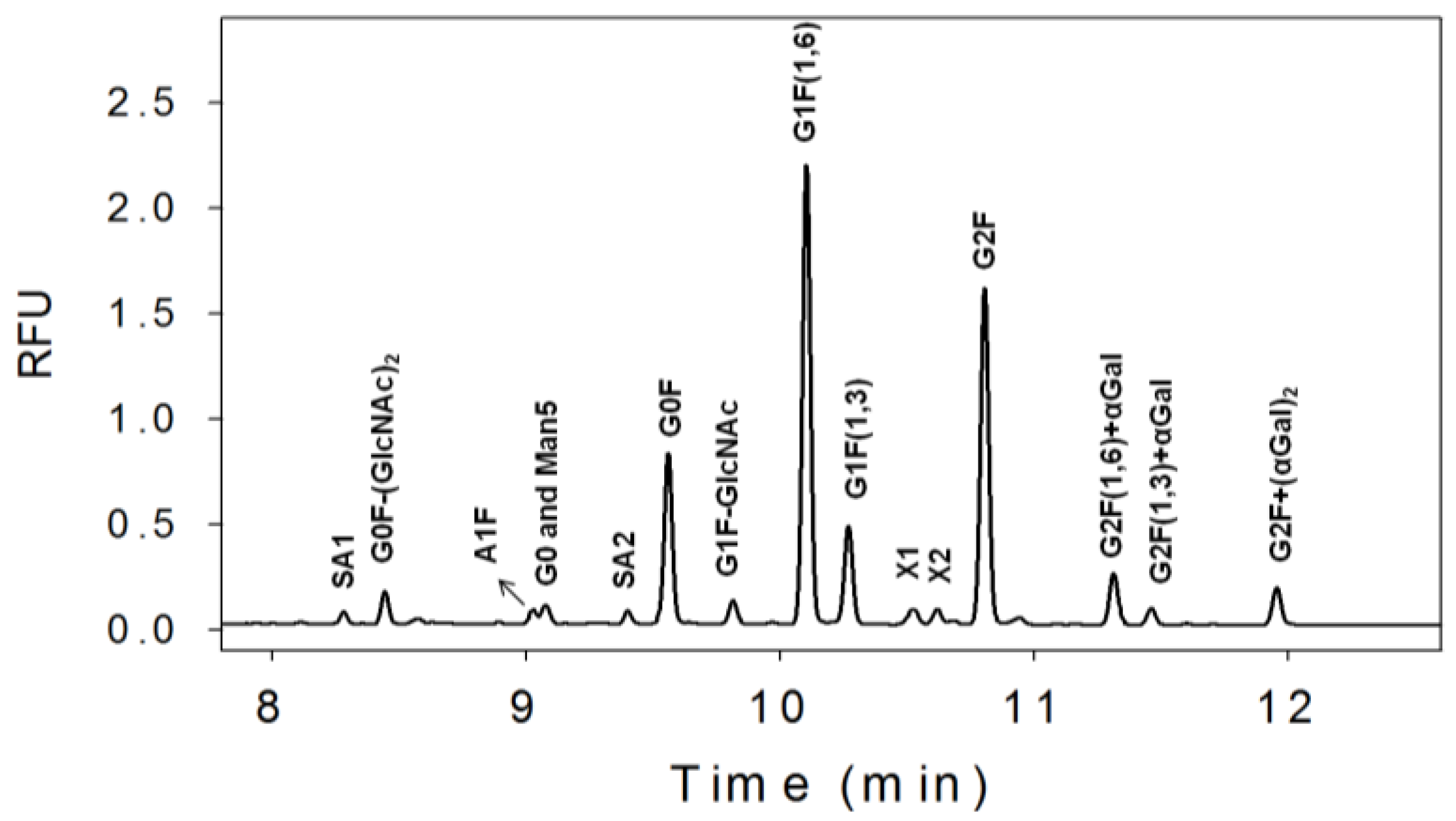
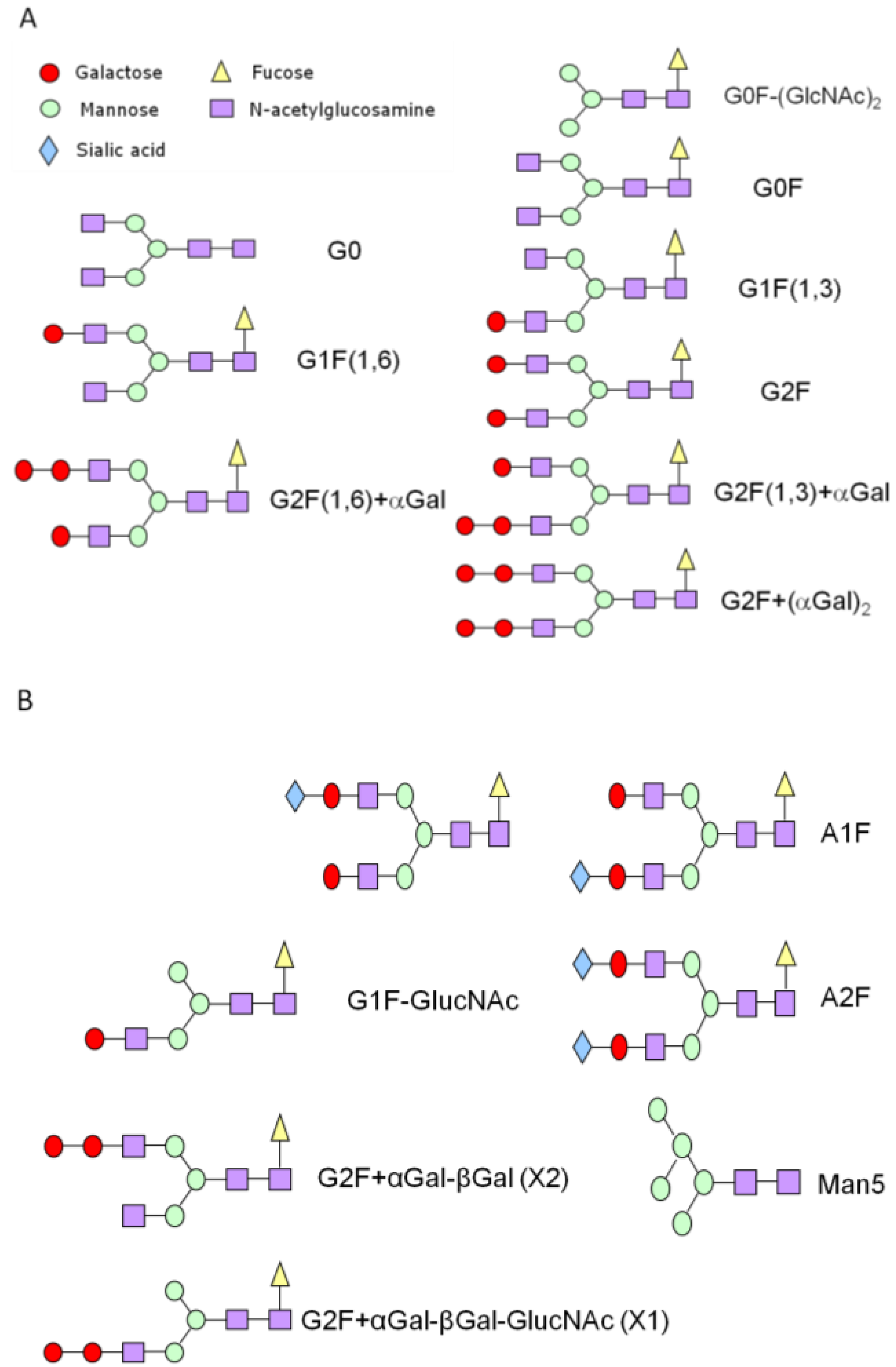
3.1. N-Linked Glycosylation Profile for mAb Produced in NS0


| % Glycan | Clone 1 | Clone 2 | Clone 3 |
|---|---|---|---|
| Sialic Acids | 3 | 1 | 1 |
| G0F-(GlcNAc)2 | 4 | 3 | 2 |
| G0 and man5 | 3 | 2 | 8 |
| G0F | 16 | 33 | 37 |
| G1F-GlcNAc | 2 | 1 | 9 |
| G1F | 43 | 44 | 35 |
| G2F | 24 | 14 | 6 |
| G2F+αGal | 4 | 2 | 1 |
| G2F+(αGal)2 | 2 | 1 | 1 |
3.2. Exoglycosidase
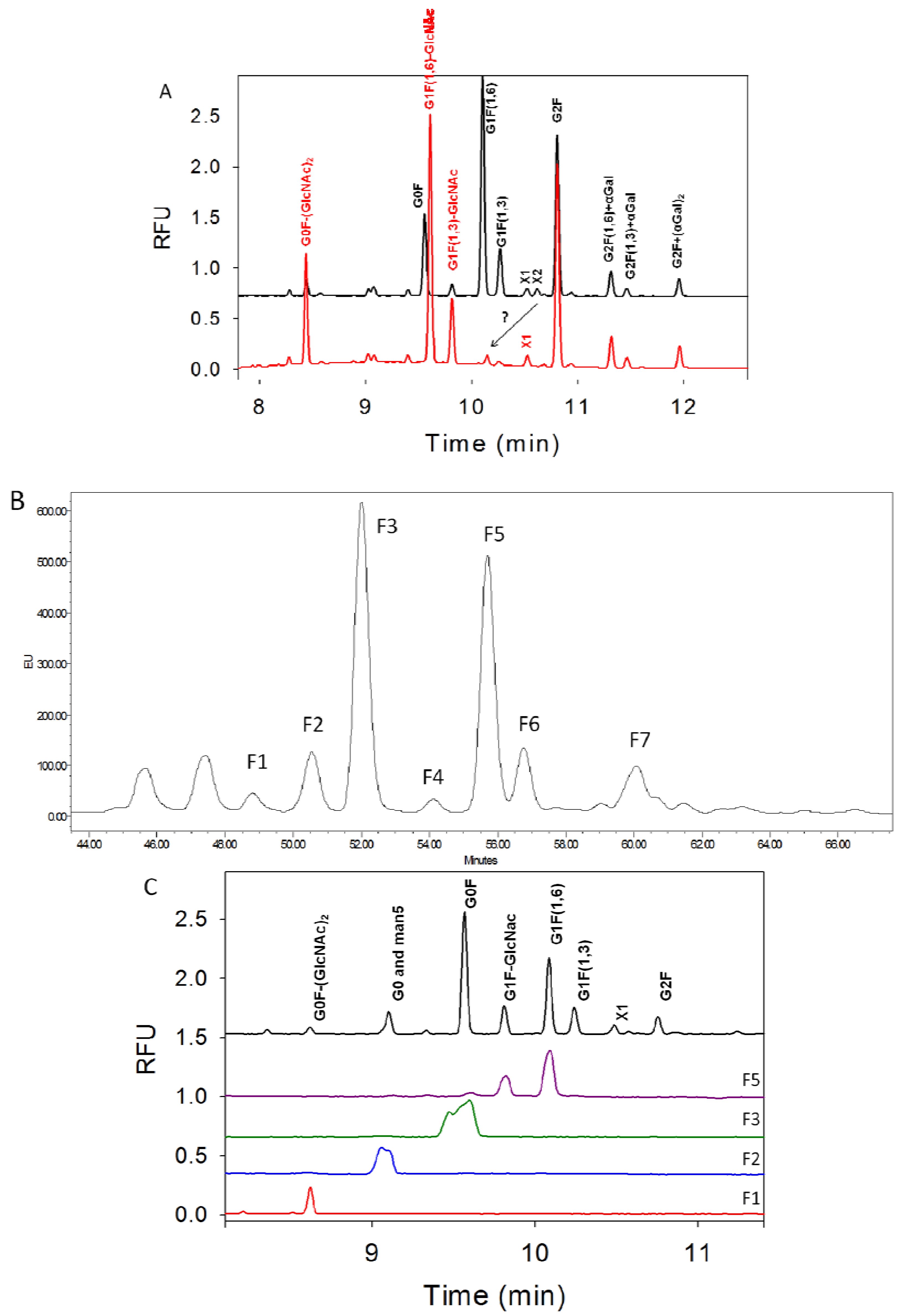
3.3. Characterization of G1F-GlcNAc Using HPLC
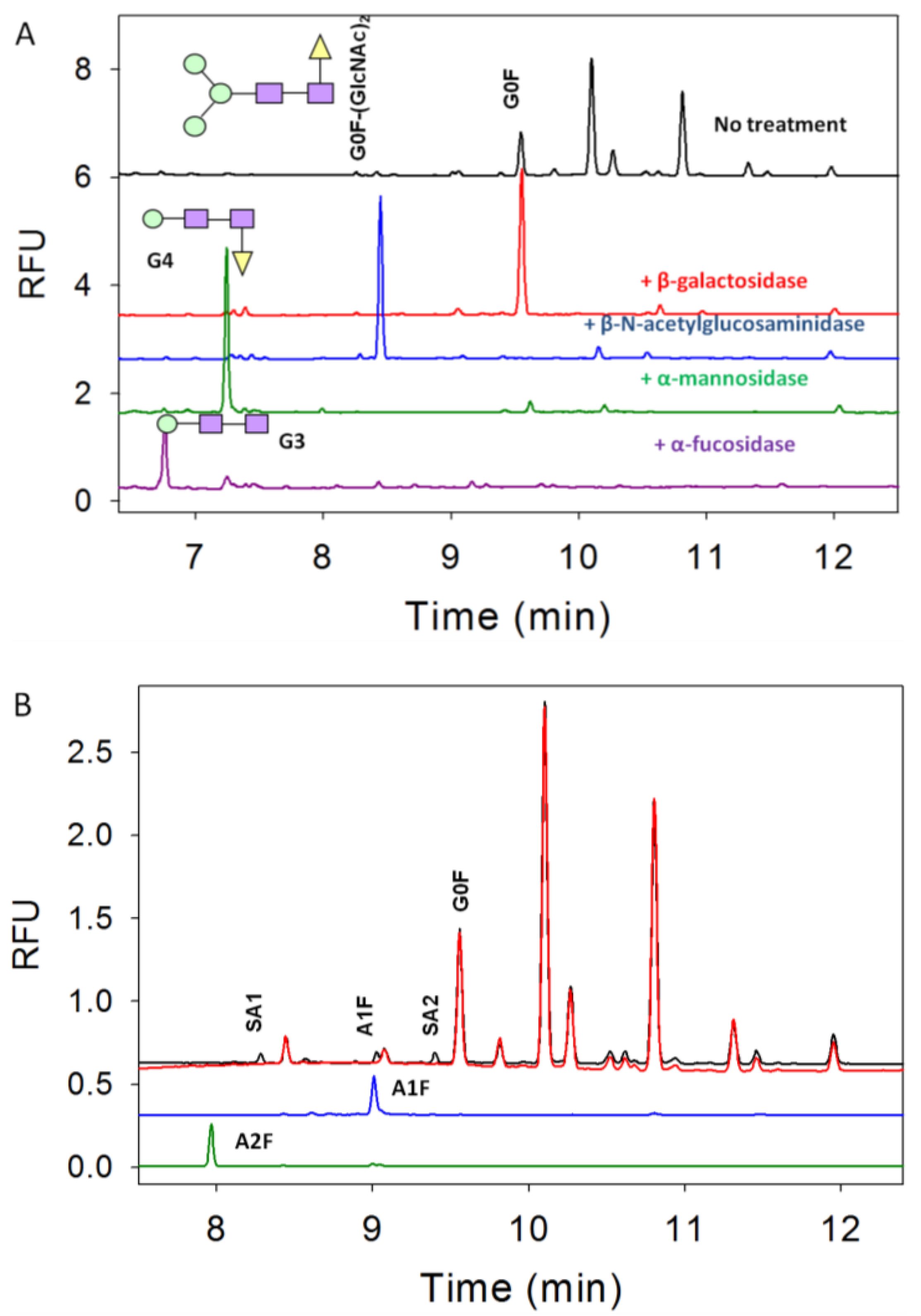

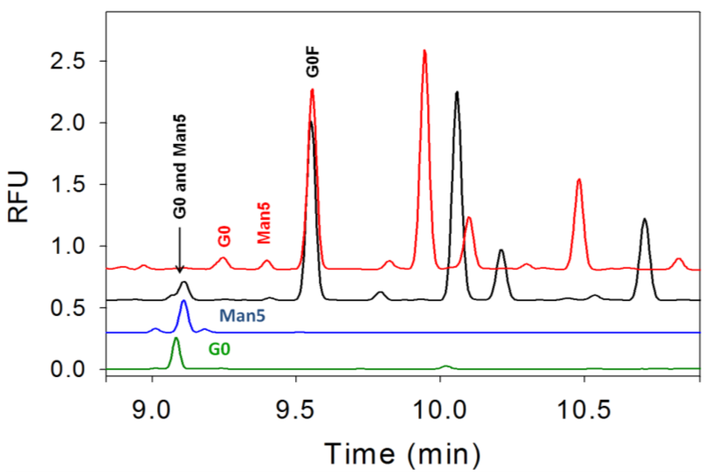
3.4. Separation of Co-Migrating Peaks of A1F, G0, and Man5
4. Conclusions
Acknowledgements
Conflict of Interest
References
- Berkowitz, S.A.; Engen, J.R.; Mazzeo, J.R.; Jones, G.B. Analytical tools for characterizing biopharmaceuticals and the implications for biosimilars. Nat. Rev. Drug Discov. 2012, 11, 527–540. [Google Scholar] [CrossRef]
- Beck, A.; Sanglier-Cianferani, S.; Van Dorsselaer, A. Biosimilar, Biobetter, and Next Generation Antibody Characterization by Mass Spectrometry. Anal. Chem. 2012, 84, 4637–4646. [Google Scholar] [CrossRef]
- Beck, A.; Wagner-Rousset, E.; Ayoub, D.; van Dorsselaer, A.; Sanglier-Cianferani, S. Characterization of Therapeutic Antibodies and Related Products. Anal. Chem. 2013, 85, 715–736. [Google Scholar] [CrossRef]
- Sutton, B.J.; Phillips, D.C. The three-dimensional structure of the carbohydrate within the Fc fragment of immunoglobulin G. Biochem. Soc. Trans. 1983, 11, 130–132. [Google Scholar]
- Ghirlando, R.; Lund, J.; Goodall, M.; Jefferis, R. Glycosylation of human IgG-Fc:influences on structure revealed by differential scanning micro-calorimetry. Immunol. Lett. 1999, 68, 47–52. [Google Scholar] [CrossRef]
- Liu, H.; Bulseco, G.G.; Sun, J. Effect of posttranslational modifications on the thermal stability of a recombinant monoclonal antibody. Immunol. Lett. 2006, 106, 144–153. [Google Scholar] [CrossRef]
- Wu, S.; Luo, J.; O’Neil, K.; Kang, J.; Lacy, E.R.; Canziani, G.; Baker, A.; Huang, M.; Tang, Q.; Raju, T.S.; et al. Structure-based engineering of a monoclonal antibody for improved solubility. Protein Eng. Des. Sel. 2010, 23, 643–651. [Google Scholar] [CrossRef]
- Raju, T.S.; Scallon, B. Fc glycan terminated with N-acetylglucosamine residues increase antibody resistance to papain. Biotechnol. Prog. 2007, 23, 964–971. [Google Scholar]
- Okazaki, A.; Shoji-Hosaka, E.; Nakamura, K.; Wakitani, M.; Uchida, K.; Kakita, S.; Tsumoto, K.; Kumagai, I.; Shitara, K. Fucose depletion from human IgG1 oligsaccharide enhances binding enthalpy and association rate between IgG1 and FcγRIIIa. J. Mol. Biol. 2004, 336, 1239–1249. [Google Scholar] [CrossRef]
- Gala, F.A.; Morrison, S.L. The role of constant region carbohydrate in the assembly and secretion of human IgD and IgA1. J. Biol. Chem. 2002, 277, 29005–29011. [Google Scholar] [CrossRef]
- Wright, A.; Sato, Y.; Okada, T.; Chang, K.; Endo, T.; Morrison, S. In vivo trafficking and catabolism of IgG1 antibodies with Fc associated carbohydrates of differing structure. Glycobiology 2000, 10, 1347–1355. [Google Scholar] [CrossRef]
- Kanda, Y.; Yamane-Ohnuki, N.; Sakai, N.; Yamano, K.; Nakano, R.; Inoue, M.; Misaka, H.; Iida, S.; Wakitani, M.; Konno, Y.; et al. Comparison of cell lines for stable production of fucose-negative antibodies with enhanced ADCC. Biotechnol. Bioeng. 2006, 94, 680–688. [Google Scholar] [CrossRef]
- Ferrara, C.; Brunker, P.; Suter, T.; Moser, S.; Puntener, U.; Umana, P. Modulation of therapeutic antibody effector functions by glycosylation engineering: Influence of Golgi enzyme localization domain and co-expression of heterologous β 1,4-N-acetylglucosaminyltransferase III and Golgi α-mannosidase II. Biotechnol. Bioeng. 2006, 93, 851–861. [Google Scholar] [CrossRef]
- Scallon, B.J.; Tam, S.H.; McCarthy, S.G.; Cai, A.N.; Raju, T.S. Higher levels of sialylated Fc glycans in immunoglobulin G molecules can adversely impact functionality. Mol. Immunol. 2007, 44, 1524–1534. [Google Scholar] [CrossRef]
- Hodoniczky, J.; Zheng, Y.Z.; James, D.C. Control of recombinant monoclonal antibody effector functions by Fc N-glycan remodeling in vitro. Biotechnol. Prog. 2005, 21, 1644–1652. [Google Scholar] [CrossRef]
- Hardy, M.R.; Townsend, R.R.; Lee, Y.C. Separation of Oligosaccharides using High Performance Anion-Exchange Chromatography with Pulsed Amperometric Detection. Methods Enzymol. 1989, 179, 65–76. [Google Scholar]
- Spellman, M. Carbohydrate Characterization of Recombinant Glycoproteins of Pharmaceutical Interest. Anal. Chem. 1990, 62, 1714–1722. [Google Scholar] [CrossRef]
- Guile, G.R.; Rudd, P.M.; Wing, D.R.; Prime, S.B.; Dwek, R.A. A rapid high-resolution HPLC method for separating glycan mixtures and analyzing oligosaccharide profiles. Anal. Biochem. 1996, 240, 210–226. [Google Scholar] [CrossRef]
- Anumula, K.R.; Dhume, S.T. High resolution and high sensitivity methods for oligosaccharide mapping and characterization by normal phase HPLC following derivatization with highly fluorescent anthranilic acid. Glycobiology 1998, 8, 685–694. [Google Scholar]
- Kamoda, S.; Nomura, C.; Kinoshita, M.; Nishiura, S.; Ishikawa, R.; Kakehi, K.; Kawasaki, N.; Hayakawa, T. Profiling analysis of Oligosaccharides in antibody pharmaceuticals by capillary electrophoresis. J. Chromatogr. A 2004, 1050, 211–216. [Google Scholar]
- Klockow, A.; Amado, R.; Widmer, H.M.; Paulus, A. Separation of 8-aminonaphthalene-1,3,6-trisulfonic acid-labelled neutral and sialylated N-linked complex oligsaccharides by capillary electrophoresis. J. Chromatogr. A 1995, 716, 241–257. [Google Scholar] [CrossRef]
- Evangelista, R.A.; Liu, M.-S.; Chen, F.-T.A. Characterization of 9-Aminopyrene-1,4,6-trisulfonate-Derivatized Sugars by Capillary Electrophoresis with Laser-Induced Fluorescence Detection. Anal. Chem. 1995, 67, 2239–2245. [Google Scholar] [CrossRef]
- Kamoda, S.; Ishikawa, R.; Kakehi, K. Capillary electrophoresis with laser-induced fluorescence detection for detailed studies on N-linked oligosaccharide profile of therapeutic recombinant monoclonal antibodies. J. Chromatogr. A 2006, 1133, 332–339. [Google Scholar] [CrossRef]
- Ma, S.; Nashabeh, W. Carbohydrate analysis of a chimeric recombinant monoclonal antibody by capillary electrophoresis with laser-induced fluorescence detection. Anal. Chem. 1999, 71, 5185–5192. [Google Scholar] [CrossRef]
- Chen, F.-T.A.; Evangelista, R.A. Profiling glycoprotien N-linked oligosaccharide by capillary electrophoresis. Electrophoresis 1998, 19, 2639–2644. [Google Scholar] [CrossRef]
- Guttman, A. High-resolution carbohydrate profiling by capillary gel electrophoresis. Nature 1996, 380, 461–462. [Google Scholar] [CrossRef]
- Gennaro, L.A.; Salas-Solano, O.; Ma, S. Capillary electrophoresis-mass spectrometry as a characterization tool for therapeutic proteins. Anal. Biochem. 2006, 355, 249–258. [Google Scholar] [CrossRef]
- Campa, C.; Coslovi, A.; Flamigni, A.; Rossi, M. Overview on advances in capillary electrophoresis-mass spectrometry of carbohydrates:A tabulated review. Electrophoresis 2006, 27, 2027–2050. [Google Scholar] [CrossRef]
- Liu, Y.; Salas-Solano, O.; Gennaro, L.A. Investigation of sample preparation artifacts formed during the enzymatic release of N-linked glycans prior to analysis by capillary electrophoresis. Anal. Chem. 2009, 81, 6823–6829. [Google Scholar] [CrossRef]
- Gahoual, R.; Burr, A.; Busnel, J.M.; Kuhn, P.; Hammann, P.; Beck, A.; Francois, Y.N.; Leize-Wagner, E. Rapid and multi-level characterization of trastuzumab using sheathless capillary electrophoresis-tandem mass spectrometry. mAb 2013, 5. in press. [Google Scholar]
- Rustandi, R.R.; Anderson, C.; Hamm, M. Application of Capillary Electrophoresis in Glycoprotein Analysis. In Glycosylation Engineering of Biopharmaceuticals Methods in Molecular Biology; Beck, A., Ed.; Springer: New York, NY, USA, 2013; Volume 988, pp. 181–197. [Google Scholar]
- Rustandi, R.R.; Washabaugh, M.W.; Wang, Y. Applications of CE SDS gel in development of biopharmaceutical antibody-based products. Electrophoresis 2008, 29, 3612–3620. [Google Scholar] [CrossRef]
- Sheeley, D.M.; Merrill, B.M.; Taylor, C.E. Characterization of Monoclonal Antibody Glycosylation: Comparison of Expression Systems and Identification of Terminal α-Linked Galactose. Anal. Biochem. 1997, 247, 102–110. [Google Scholar] [CrossRef]
- Beck, A.; Bussat, M.-C.; Zorn, N.; Robillard, V.; Klinguer-Hamour, C.; Chenu, S.; Goetsch, L.; Corvaia, N.; Van Dorsselaer, A.; Haeuw, J.-F. Characterization by liquid chromatography combined with mass spectrometry of monoclonal anti-IFG-1 receptor antibodies produced in CHO and NS0 cells. J. Chromatogr. B 2005, 819, 203–218. [Google Scholar] [CrossRef]
- Ghaderi, D.; Taylor, R.E.; Padler-Karavani, V.; Diaz, S.; Varki, A. Implications of the presence of N-glycolylneuraminic acid in recombinant therapeutic glycoproteins. Nat. Biotechnol. 2010, 28, 863–867. [Google Scholar] [CrossRef]
- Galili, U. Immune Response, Accomodation, and Tolerance to Transplantation Carbohydrate Antigens. Transplantation 2004, 78, 1093–1098. [Google Scholar] [CrossRef]
- Chung, C.H.; Mirakhur, B.; Chan, E.; Le, Q.-T.; Berln, J.; Morse, M.; Murphy, B.A.; Satinover, S.M.; Hosen, J.; Mauro, D.; et al. Cetuximab-Induced Anaphylaxis and IgE Specific for Galactose-α-1,3-Galactose. New Engl. J. Med. 2008, 358, 1109–1117. [Google Scholar] [CrossRef]
- Commins, S.P.; Platts-Mills, T.A.E. Allergenicity of Carbohydrates and Their Role in Anaphylactic Events. Curr. Allergy Asthma Res. 2010, 10, 29–33. [Google Scholar] [CrossRef]
- Goetze, A.M.; Liu, Y.D.; Zhang, Z.; Shah, B.; Lee, E.; Bondarenko, P.V.; Flynn, G.C. High-mannose glycans on the Fc region of therapeutic IgG antibodies increase serum clearance in humans. Glycobiology 2011, 21, 949–959. [Google Scholar] [CrossRef]
- Jiang, X.-R.; Song, A.; Bergelson, S.; Arroll, T.; Parekh, B.; May, K.; Chung, S.; Strouse, R.; Mire-Sluis, A.; Schenerman, M. Advances in the assessment and control of the effector functions of therapeutic antibodies. Nat. Rev. Drug. Discov. 2011, 10, 101–110. [Google Scholar]
© 2013 by the authors; licensee MDPI, Basel, Switzerland. This article is an open access article distributed under the terms and conditions of the Creative Commons Attribution license (http://creativecommons.org/licenses/by/3.0/).
Share and Cite
Hamm, M.; Wang, Y.; Rustandi, R.R. Characterization of N-Linked Glycosylation in a Monoclonal Antibody Produced in NS0 Cells Using Capillary Electrophoresis with Laser-Induced Fluorescence Detection. Pharmaceuticals 2013, 6, 393-406. https://doi.org/10.3390/ph6030393
Hamm M, Wang Y, Rustandi RR. Characterization of N-Linked Glycosylation in a Monoclonal Antibody Produced in NS0 Cells Using Capillary Electrophoresis with Laser-Induced Fluorescence Detection. Pharmaceuticals. 2013; 6(3):393-406. https://doi.org/10.3390/ph6030393
Chicago/Turabian StyleHamm, Melissa, Yang Wang, and Richard R. Rustandi. 2013. "Characterization of N-Linked Glycosylation in a Monoclonal Antibody Produced in NS0 Cells Using Capillary Electrophoresis with Laser-Induced Fluorescence Detection" Pharmaceuticals 6, no. 3: 393-406. https://doi.org/10.3390/ph6030393
APA StyleHamm, M., Wang, Y., & Rustandi, R. R. (2013). Characterization of N-Linked Glycosylation in a Monoclonal Antibody Produced in NS0 Cells Using Capillary Electrophoresis with Laser-Induced Fluorescence Detection. Pharmaceuticals, 6(3), 393-406. https://doi.org/10.3390/ph6030393