Magnetic Effect on the Performance of a Four-Frequency Differential Laser Gyroscope

Abstract
1. Introduction
2. Theoretical Principle
2.1. Principle of FFDLG
2.2. Theoretical Principles of FFDLG and the Sources of Magnetic Effect in FFDLG
2.3. Optimal Operating Point Control and Dispersion Balance Control
3. Experiment Scheme
3.1. Generation of the High-Frequency Alternating Magnetic Field
3.2. Calculation for Error Induced by Magnetic Field
3.3. Feedback Control Logic for the Operating Point
3.4. Iterative Calibration and Long-Term Maintenance
4. Experiment Verification
- The gyroscope was preheated for over 2 h. The error calculation and adjustment cycle for frequency stabilization operating point was set to 25 s;
- Two magnetic fields with different amplitudes were applied. For each amplitude, the frequency was varied across seven levels to identify the corresponding error induced by magnetic field and optimal operating point;
- For each condition, seven experimental runs were performed. In the first six runs, the frequency stabilization circuit was set the position that light intensity voltage difference between RCP and LCP beams was zero. The errors induced by magnetic field from these runs were recorded and averaged to obtain the average error. In the seventh run, the operating point was adjusted to identify the optimal operating point, the position where the magnetic field did not affect the FFDLG output. The position of the optimal operating point defined as proportion between the light intensity voltage difference of RCP and LCP and the light intensity voltage sum of RCP and LCP, and was recorded in percentage;
- The gyroscope remained powered throughout the entire process to eliminate error induced by repeated restarts;
- An additional test was conducted under a low-amplitude magnetic field to evaluate the optimal operating point at frequencies of 0.04 Hz and 4 KHz.
5. Data Analysis and Conclusions
5.1. Data Analysis
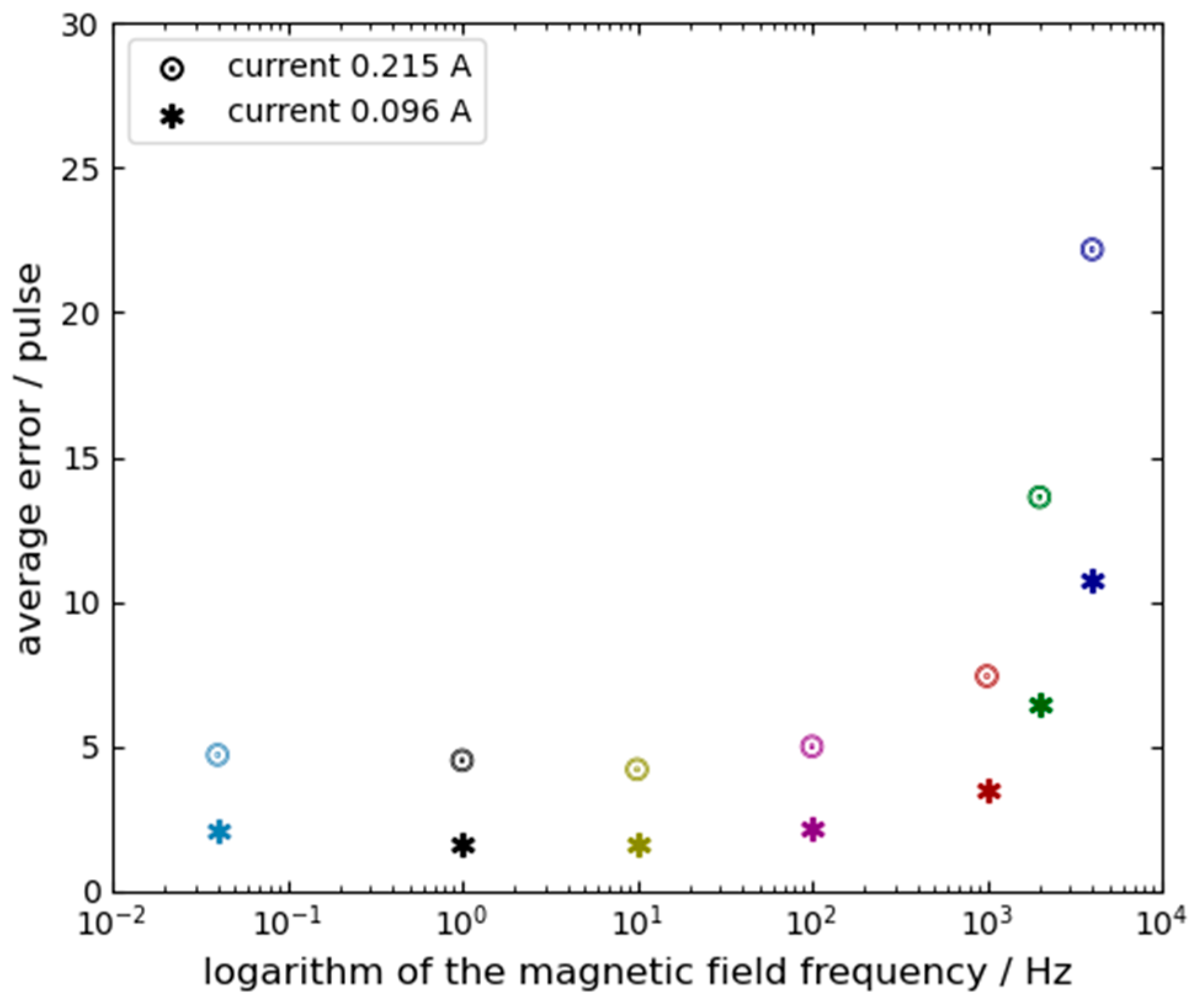
- Based on the data in Table 1 and the trends shown in Figure 5 and Figure 6, several observations can be made: First, when the magnetic field frequency exceeds 100 Hz, the position of the optimal operating point and the average error are significantly affected by the frequency and amplitude of the magnetic field. The impact intensifies as either the frequency or the amplitude increases. Therefore, the position of the optimal operating point is decided by both the frequency and the amplitude of the magnetic field. Second, when the magnetic field frequency is lower than 100 Hz, the position of the optimal operating point becomes relatively insensitive to variations in the frequency and amplitude of magnetic field;
- From Table 1, it can also be concluded that the frequency of the magnetic field remains a critical factor influencing the position of the operating point even under low-amplitude magnetic field.
5.2. Conclusions
- A FFDLG does not have the universal “optimal operating point” that can ensure insensitivity to all external magnetic fields. In fact, the position of the optimal operating point is dynamic, shifting according to the frequency and amplitude of the magnetic field;
- Consequently, it is challenging to take the optimal operating point to eliminate the FFDLG magnetic-induced error sin practical applications, which limits the practical utility of this approach. This is because environmental magnetic fields are unknown, so which optimal operating point should be chosen cannot be determined.
6. Primary Recognition of Physical Origin
7. Further Experimental Validation
8. Analysis Data Again
- External magnetic fields directly perturb the plasma motion within the gain region. Unlike the Zeeman effect, whose induced error reverses direction when the gyroscope’s operating state is switched, the error caused by Lorentz-force-driven plasma motion maintains the same direction regardless of the operating state;
- At high frequencies, the error induced by magnetic fields via the Lorentz force dominates, while the relative contribution of the Zeeman effect is significantly smaller. Consequently, the main magnetic field effect error is the error induced by the plasma motion by Lorentz force, the optimal operating point’s direction remains the same across different operating states because it is primarily governed by the Lorentz force. At low frequencies, the Lorentz-force-induced error is reduced, allowing the Zeeman effect to become the primary source of error. Therefore, the main magnetic field effect error is the Zeeman effect error, the optimal operating point shifts in opposite directions when the gyroscope state is switched, consistent with Zeeman theory;
- Under a static magnetic field, the Lorentz-force-induced error manifests as a constant or quasi-static bias. This bias is often inadvertently merged with the Zeeman error, making it difficult to distinguish. This also confirm that the magnetic effects in the FFDLG are not limited to the Zeeman effect alone.
9. Conclusions
9.1. Conclusions of This Paper
- The FFDLG does not possess a universal “optimal operating point” that renders it insensitive to external magnetic fields across all frequencies and amplitudes. Instead, the position of this optimal point is dynamic, varying significantly as a function of the magnetic field’s frequency and amplitude;
- Similar conclusions apply to Mechanically Dithered Ring Laser Gyros (MDRLG). In these devices, magnetic fields also alter plasma motion via the Lorentz force, leading to Doppler shifts and additional drift. This effect has likely been overlooked in previous laboratory tests because typical sampling intervals (e.g., 1 s or 10 s) tend to average out alternating magnetic field errors into a quasi-static bias. Furthermore, since high-frequency magnetic field testing is uncommon, the Lorentz-force-induced error under static fields is often inadvertently conflated with the Zeeman effect error, remaining largely undetected;
- The sensitivity of plasma motion to external magnetic fields restricts the practical utility of optimal operating point control schemes. This limitation is particularly pronounced in environments with high-frequency magnetic interference, where alternating magnetic field errors intensify. In such cases, a selected optimal operating point may only be effective for a specific high-frequency component rather than providing broad-spectrum protection against varying magnetic interference.
9.2. Some Discussions About “The Optimal Frequency Stabilization Operating Point” in Practical Application
- If the characteristics of external magnetic fields are well-characterized in a specific application, the operating point can be dynamically adjusted to suppress magnetic-induced errors. In such cases, the “optimal frequency stabilization operating point” remains a viable approach;
- For applications with low output frequency requirements, a low-frequency magnetic field can be applied to modulate the operating point. This effectively mitigates errors induced by low-frequency external fields, making the optimal operating point control applicable;
- In high-frequency applications, such as inertial navigation systems and attitude control, the optimal operating point can be determined using a low-frequency magnetic field prior to system installation or during the pre-deployment startup phase. Once identified, the gyroscope can be maintained at this stabilized point throughout its operation to reduce low-frequency magnetic interference;
- Robust magnetic shielding remains the fundamental solution for minimizing magnetic-induced errors. The utility of the “optimal operating point” method is inherently limited on its own. However, when integrated with high-performance shielding, the benefits are compounded: the operating point control handles residual low-frequency deviations, while the shielding effectively attenuates high-frequency interference. This combined approach can reduce magnetic-induced drift to negligible levels.
Author Contributions
Funding
Institutional Review Board Statement
Informed Consent Statement
Data Availability Statement
Conflicts of Interest
References
- Volk, C.H.; Gillespie, S.C.; Mark, J.G.; Tazartes, D.A. Multioscillator ring laser gyroscopes and their applications. RTO AGARD Opt. Gyros Their Appl. 1999, 352. [Google Scholar]
- Martin, G.J.; Gillespie, S.C.; Volk, C.H. The Litton 11cm triaxial zero-lock gyro. In Proceedings of the IEEE Position, Location and Navigation Symposium (PLANS ‘96), Atlanta, GA, USA, 22–25 April 1996; pp. 49–55. [Google Scholar]
- Martin, G.J.; Gillespie, S.C.; Volk, C.H. Small ZLG triax technology. In Proceedings of the International Symposium on Gyro Technology, Stuttgart, Germany, 17–18 September 1996. [Google Scholar]
- Wang, Z. Design and realization of the rate stability apparatus based on the laser gyroscopes. Chin. J. Sens. Actuators 2008, 21, 1524–1527. [Google Scholar]
- Vimal, A.; Nicholas, J.S.; Navin, R.; Raj, K.P.; Kiruba, P. Ring laser gyroscope technology: A review of precision navigation and sensing applications. J. Phys. Conf. Ser. 2025, 3045, 012016. [Google Scholar] [CrossRef] [Scilit]
- Azarova, V.V.; Golyaev, Y.D.; Savelyev, I.I. Zeeman laser gyroscopes. Quantum Electron. 2015, 45, 171–179. [Google Scholar] [CrossRef] [Scilit]
- Kolbas, Y.Y.; Savel’ev, I.I.; Khokhlov, N.I. Effect of external and internal magnetic fields on the bias stability in a Zeeman laser gyroscope. Quantum Electron. 2015, 45, 573–581. [Google Scholar] [CrossRef] [Scilit]
- Broslavets, Y.Y.; Milikov, E.A.; Tarasenko, A.B.; Larionov, P.V.; Semenov, V.G.; Filatov, P.A.; Polukeev, E.A.; Kolchev, A.B.; Fomichev, A.A.; Varenik, A.I.; et al. New Four-Frequency Zeeman Laser Gyroscope with a Nonplanar Symmetric Cavity, its Parameters and Operation. In Proceedings of the 2021 28th Saint Petersburg International Conference on Integrated Navigation Systems (ICINS), Saint Petersburg, Russia, 31 May–2 June 2021; pp. 1–4. [Google Scholar]
- Sinelnikov, A. Analysis of Ring Laser Gyroscope Cavity Thermal Deformations. Adv. Syst. Sci. Appl. 2025, 25, 120–130. [Google Scholar]
- Sinelnikov, A.; Zubarev, Y.A.; Fetisova, N.E. Analysis of Ring Laser Gyro Errors during Path Length Active Stabilization. ResearchGate 2025. Preprint. [Google Scholar]
- Aronowitz, F. The Laser Gyro. In Laser Applications; Academic Press: Cambridge, MA, USA, 1971; Volume 1, pp. 133–200. [Google Scholar]
- Giovinetti, F.; Altucci, C.; Bajardi, F.; Basti, A.; Beverini, N.; Capozziello, S.; Carelli, G.; Castellano, S.; Ciampini, D.; Di Somma, G.; et al. GINGERINO: A high sensitivity ring laser gyroscope for fundamental and quantum physics investigation. Front. Quantum Sci. Technol. 2024, 3, 1363409. [Google Scholar] [CrossRef] [Scilit]
- Chow, W.W.; Gea-Banacloche, J.; Pedrotti, L.M.; Sanders, V.E.; Schleich, W.; Scully, M.O. The ring laser gyro. Rev. Mod. Phys. 1985, 57, 61–104. [Google Scholar] [CrossRef] [Scilit]
- Smith, I.W.; Dorschner, T.A. Biasing the Ray Laser Gyro. Proc. SPIELaser Inert. Rotat. Sens. 1978, 157, 21–29. [Google Scholar]
- Wang, Z.; Long, X.; Wang, F.; Yuan, J. Magnetic sensitivity and optimal operating point of four-frequency differential laser gyroscope. Acta Opt. Sin. 2009, 29, 3202–3206. [Google Scholar] [CrossRef] [Scilit]
- Statz, H.; Dorschner, T.A.; Hollinger, M.; Schulz, I.A. The Multioscillator Ring Laser Gyroscope. In Laser Handbook; Stitch, M.L., Bass, M., Eds.; North-Holland: Amsterdam, The Netherlands, 1985; Volume 4, pp. 229–332. [Google Scholar]
- Dorschner, T.A.; Haus, H.A.; Holz, M.; Smith, I.W.; Statz, H. Laser gyro at quantum limit. IEEE J. Quantum Electron. 1980, 16, 1376–1389. [Google Scholar] [CrossRef]
- Lamb, W.E., Jr. Theory of an Optical Maser. Phys. Rev. 1964, 134, A1429–A1450. [Google Scholar] [CrossRef] [Scilit]
- Menegozzi, L.N.; Lamb, W.E. Theory of a Ring Laser. Phys. Rev. A 1973, 8, 2103–2125. [Google Scholar] [CrossRef] [Scilit]


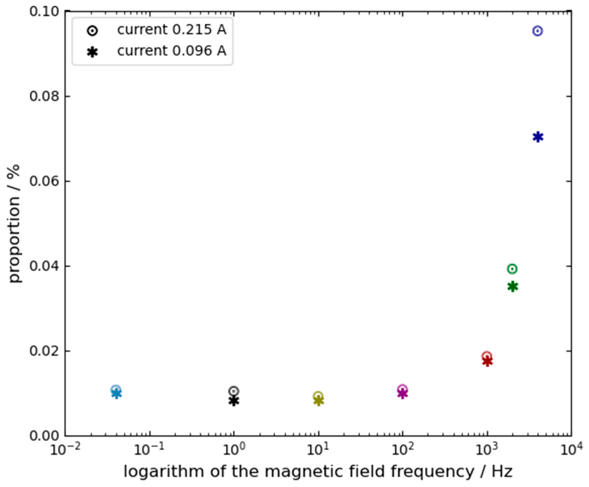

| Current amplitude is 0.215 A | |||||||
| Current frequency | 4 KHz | 2 KHz | 1 KHz | 100 Hz | 10 Hz | 1 Hz | 0.04 Hz |
| Average error | 22.17 | 13.62 | 7.44 | 5.01 | 4.22 | 4.53 | 4.72 |
| Percent | 9.52% | 3.92% | 1.86% | 1.08% | 0.92% | 1.04% | 1.07% |
| Current amplitude is 0.096 A | |||||||
| Current frequency | 4 KHz | 2 KHz | 1 KHz | 100 Hz | 10 Hz | 1 Hz | 0.04 Hz |
| Average error | 10.72 | 6.43 | 3.53 | 2.17 | 1.65 | 1.66 | 2.07 |
| Percent | 7.03% | 3.51% | 1.77% | 1.01% | 0.84% | 0.84% | 1.00% |
| Current amplitude is 0.016 A | |||||||
| Current frequency | 4 KHz | 2 KHz | 1 KHz | 100 Hz | 10 Hz | 1 Hz | 0.04 Hz |
| Average error | 1.89 | --- | --- | --- | --- | --- | 0.302 |
| Percent | 5.80% | --- | --- | --- | --- | --- | 0.85% |
| Current amplitude is 0.215 A | ||
| Current frequency | 4 KHz | 0.04 Hz |
| Average error | 14.54 | −10.095 |
| Percent | 5.60% | −1.78% |
| Current amplitude is 0.096 A | ||
| Current frequency | 4 KHz | --- |
| Average error | 6.25 | --- |
| Percent | 3.74% | --- |
Disclaimer/Publisher’s Note: The statements, opinions and data contained in all publications are solely those of the individual author(s) and contributor(s) and not of MDPI and/or the editor(s). MDPI and/or the editor(s) disclaim responsibility for any injury to people or property resulting from any ideas, methods, instructions or products referred to in the content. |
© 2026 by the authors. Licensee MDPI, Basel, Switzerland. This article is an open access article distributed under the terms and conditions of the Creative Commons Attribution (CC BY) license.
Share and Cite
Wang, G.; Li, J. Magnetic Effect on the Performance of a Four-Frequency Differential Laser Gyroscope. Sensors 2026, 26, 1927. https://doi.org/10.3390/s26061927
Wang G, Li J. Magnetic Effect on the Performance of a Four-Frequency Differential Laser Gyroscope. Sensors. 2026; 26(6):1927. https://doi.org/10.3390/s26061927
Chicago/Turabian StyleWang, Guochen, and Jiaqi Li. 2026. "Magnetic Effect on the Performance of a Four-Frequency Differential Laser Gyroscope" Sensors 26, no. 6: 1927. https://doi.org/10.3390/s26061927
APA StyleWang, G., & Li, J. (2026). Magnetic Effect on the Performance of a Four-Frequency Differential Laser Gyroscope. Sensors, 26(6), 1927. https://doi.org/10.3390/s26061927