Abstract
In this paper, a flexible rectangular loop antenna is designed and proposed for ice, frost and wildfire detection. The antenna is composed of two concentric rings made of a flexible conductor. The proposed antenna was responsive to different materials based on distinct shifts in the resonant frequency, which was employed to differentiate between these materials. The antenna provides a wide response and sensitivity range to detect ice or frost with relative permittivity close to 3 and water with relative permittivity close to 72 at the same time. This wide sensitivity level is attributed to the internal loop which works with the external ring to form a capacitor with a capacitance varying with the relative permittivity of the material under test. The internal loop also enhances coupling with the material under test and fine-tunes the antenna’s response. The antenna achieved a maximum radiation efficiency of 97.1% and gain of 2.83 dBi at 2.45 GHz across the tested scenarios involving frost and ice. It also obtains a maximum radiation efficiency and gain of up to 6.67% and −8.27 dBi, respectively, for water at 40 °C and 50 °C, respectively. Additionally, the antenna preserves the same direction of maximum radiation for all of the investigated materials, which minimizes constraints on the receiving antenna’s radiation pattern requirements. The proposed antenna features simplicity, robust performance and a wide sensitivity range over temperatures between 0 and 50 °C, which makes it a good candidate for environmental monitoring.
1. Introduction
In addition to data transmission, antennas have been recently used as sensors for applications such as early warning and environmental monitoring. In such systems, the antenna is employed to detect natural disasters or to sense an environmental parameter and send a corresponding alarm signal to an external receiver. This reduces the hardware and power consumption needed if sensors separate from antennas are used [1,2,3,4,5]. In addition, it allows accurate and rapid notification.
Antennas in general are usually required to satisfy a set of specifications including sufficient gain, robust performance and good impedance matching. They can be made of a single element or arranged in an array of multiple elements. While antenna arrays may boost the gain, improve the radiation pattern and help in interference cancellation [6], they increase the system complexity. Sensor antennas need to meet further requirements such as the ability to detect slight variations in their surrounding environment. They are also required to distinguish between different materials with very similar dielectric properties.
These requirements, in addition to compactness and ease of integration with existing system components, need accurate design considerations involving the following:
- -
- Specific miniaturization techniques that should maintain good inclusion of the sensing elements within the structure. Inclusion of split rings and complementary split rings could be a good candidate in this case [7,8].
- -
- Effective near-electromagnetic field control. As a sensor, the antenna needs to couple with the material under test [9]. Again, structures based on rings and loops can work to improve the capacitive electric and magnetic field coupling, which plays a major role in improving sensitivity [10].
In systems such as early warning systems, the sensor antenna is also required to maintain robust performance under harsh conditions accompanying natural disasters [11]. Specific examples include frost damage and wildfire, which can be detected by the antenna at an early stage before their occurrence.
An example of an early warning system is depicted in Figure 1, where the antenna detects the upcoming disaster such as frost or wildfire and transmits the alarm data to an external receiver, which could be a fixed base station or a mobile autonomous aerial vehicle (UAV). Hence, in such a system the sensor antenna must fulfill additional design requirements such as an omnidirectional radiation pattern [12] to allow data transmission for both the fixed base station and the mobile UAV at the same time.
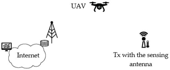
Figure 1.
A typical wireless natural disaster early warning system.
Various sensor antennas have been proposed in the literature for various applications. The antenna in [4] was used for sensing strain and humidity; a dipole antenna was designed based on inkjet printing of a copper layer on a Polyimide film. Sensing was obtained by measuring the resonant frequency shift in response to the antenna stretching under different humidity and strain levels. In [13], a closed S-shaped monopole antenna was presented as an implantable sensor for detecting breast tumors. Detection of the surrounding tissue composition was enabled by analyzing its resonance frequency. A flexible, wearable patch antenna was introduced in [14] for pressure sensing, featuring a resonant frequency of 4.8 GHz and a frequency shift range of 8% under different strain conditions. Another wearable sensor antenna was presented in [15]. It was a textile monopole capable of breast cancer detection and monitoring over the 1.8 to 10 GHz ISM band. Different parameters, including the resonant frequency, matching level and transmission coefficient, were used for detecting the tumor’s existence and size. Antennas designed for detecting material compositions have also been investigated, with examples provided in [16,17]. The same concept of varying the antenna’s resonant frequency in response to variations in the dielectric permittivity of the material under test was employed.
Sensor antennas have been also proposed for early warning systems and environmental monitoring. The most common type is the patch antenna, which can accommodate various slots and structures that facilitate coupling. In [18], a T-slot antenna was proposed for ice and frost detection at 2.45 GHz, while another patch antenna with a cross slot was introduced in [1] for sensing at 5.6 GHz. A substrate-integrated waveguide (SIW) antenna was also developed in [19] and presented for ice, frost and wildfire detection at 5.6 GHz. Although the design incorporated smart sensing capabilities supported by Machine Learning (ML), it featured several holes with small radii and short spacing, making it complex to fabricate. The study in [20] compared two antenna designs, a loop and a dipole, demonstrating that the loop antenna exhibited higher sensitivity than the dipole antenna.
Loop and ring antennas in general feature many characteristics, including ease of integration and conformity to many designs and structures. They can be in different shapes, such as circular or rectangular, or they can even fit to specific conformal structures [21]. The loop antenna can also obtain different polarization types such as circular polarization, which is appealing for different applications [22]. It can host split rings and complementary split rings, which provide a set of appealing features as discussed above [23]. Moreover, it can be optimized to control near electromagnetic fields [24].
All of these appealing features proved by the promising performance of the loop antenna in [20] inspired the investigations and design presented in this work, which seeks to further study and investigate loop antennas for sensing.
This work utilizes an internal rectangular loop coupled with an external feeding loop to control the area of coupling with the material under test (MUT). This results in adjusting the sensitivity level accordingly. The proposed antenna can detect different materials resembling ice, frost and water at 40 °C and 50 °C, mimicking wildfire conditions. The overall antenna performance for both sensing and data transmission is analyzed, evaluated and validated. The antenna proposed in this work is likely the first loop antenna with demonstrated detection capabilities for ice, frost and wildfire simultaneously.
This paper is organized as follows:
First, the design structure and concept are presented in Section 2. Next, the methodology and methods employed in this research are outlined in Section 3. The scenarios for both data sensing and transmission are then simulated and discussed and analyzed in Section 4, which also includes link budget calculations. Simulation results relevant to ice are then validated through measurements in Section 5. Finally, the paper is concluded in the last section.
2. Structures and Concept
The proposed antenna is composed of two rectangular loops coupled to each other. It is made of a flexible conductor (copper tape). The antenna structure is shown in Figure 2.
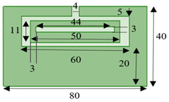
Figure 2.
The proposed antenna structure; dimensions in mm.
The structure and materials were selected to obtain the following objectives:
- Flexible materials were selected for the radiator due to their appealing features, including light weight and conformability [25].
- A loop structure was chosen and investigated in this work. This is because of its simplicity, making it well-suited for integration with flexible materials. Additionally, as mentioned earlier, loop antennas have been shown to be more sensitive than dipole antennas for ice detection applications [20].
Moreover, multiple concentric rings can be integrated within each other. This provides an area of coupling with the material under test. This coupling controls the effective capacitance of a parallel plate capacitor assembled from two rings separated by a dielectric in this case. The resulting capacitance also contributes to fine-tuning the antenna’s resonance and optimizing its impedance matching at 2.49 GHz [26,27].
where (F) is the total effective capacitance and (H) is the total effective inductance.
The loop antenna also provides an omnidirectional radiation pattern. This pattern type is preferred in such applications in order to guarantee radiation from the sensor antennas to receivers in different directions.
- Resonance at around 2.49 GHz is within the 2.4–2.5 GHz Industrial, Scientific and Medical (ISM) band. This is an unlicensed band compatible with a wide range of wireless technologies, including sensor networks. The 2.45 GHz ISM band offers several advantages for early warning systems, such as moderate range and good penetration through foliage, rain and obstacles, which supports effective sensing in outdoor environments, particularly for frost, flood and wildfire detection. This band experiences lower atmospheric attenuation if compared with others at higher frequencies such as 5.6 GHz. This ensures a longer range of communication or more robust communication at shorter distances. Additionally, lower power consumption is usually associated with this band, which extends the lifetime of the battery-powered system. Also, many technologies have already been deployed utilizing this frequency band. Hence, real-time data collection and transmission can be supported for early warning systems utilizing the existing infrastructure [28].
The proposed antenna is supposed to detect ice or frost. Its performance is assessed through variations in the resonant frequency for the different materials under test. The change in the effective dielectric constant value () from one material to another causes the resonant frequency to alter as follows [29]:
where in Hz is the original resonant frequency without loading and in Hz is the resonant frequency for the antenna when loaded with the material under test.
Due to the different relative permittivity values for the different materials under test, such as ice and frost, the resonant frequency values vary differently in response to these materials. A solid layer on the antenna surface is used to model ice and frost while a layer of water heated up to 40 °C and 50 °C is used to resemble wildfire conditions, in correspondence with the work in [19]. The relative permittivity and conductivity of the materials investigated in this paper are summarized in Table 1 [1,19]. A temperature of 40 °C is considered sufficiently high to trigger the early warning system for wildfire [19].

Table 1.
Relative permittivity and conductivity of the investigated materials under test at 2.45 GHz.
It is worth indicating that the relative permittivity of materials is frequency-dependent in general. It decreases with frequency [30]. However, it can be considered approximately constant for the investigated materials listed in Table 1 over the relatively narrow frequency range around 2.45 GHz [31,32]. The data provided in Table 1 correspond to 2.45 GHz. On the other hand, the effective relative permittivity increases with the layer thickness [33]. This variation is utilized as a distinguishing feature to differentiate between distinct ice accumulation levels. This will be further explained in the following parts of the paper.
It is important to note that the proposed antenna should maintain a wide sensitivity range which is broad enough to include both the wildfire and frost scenarios despite the large difference between their corresponding relative permittivity values. This is obtained for the proposed design by controlling the effective capacitance, which varies with the effective permittivity. This will be explained in the following section.
3. Methodology and Methods
To assess the antenna performance and validate the concept, the following methodology is employed and followed:
- Design the antenna using simulation software with reference to theoretical basics. Computer Simulation Technology (CST) is used for this work [34]. Hexahedral meshes and a time-domain solver are used. A simulation accuracy of −40 dB is set, ensuring excellent convergence and stability and providing reliable and accurate results. In addition, open boundaries are selected to minimize reflections, which provides more accurate near and far field results and allows for modeling free space radiation accurately. The simulations are also run with a port impedance of a pure 50 Ohms resistance, ensuring compatibility with a real standard value for practical connectors.
- Simulate the antenna in free space under the following conditions:
- -
- Without any loading materials;
- -
- With a layer of ice-mimicking material;
- -
- With a layer of frost-mimicking material;
- -
- With water-equivalent material at 40 °C and 50 °C.
All the dielectric properties of the simulated layers are provided in Table 1. A layer thickness of 1 mm is employed at this stage. The antenna with the materials under test is shown in Figure 3.
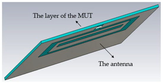
Figure 3.
The proposed antenna with the material under test.
The simulations at this stage assume the following:
- -
- Free space conditions, excluding other parameters such as humidity and smoke;
- -
- A steady material status during the overall duration of the simulation (i.e., it is not melted or starting to melt);
- -
- The layer of the MUT is uniform;
- -
- Fixed dielectric properties for materials over the entire simulation frequency range;
- -
- A perfect conducting radiator.
- Study and analyze the simulated results. The key parameters (−10 dB matching, variations in the resonant frequency, radiation efficiency, gain, radiation pattern, communication distance) are evaluated at this stage. The effect of the ice layer thickness on the antenna performance is also evaluated at this stage.
- Validate the antenna performance. The antenna is fabricated at this stage and its reflection coefficient along with its resonant frequency are measured for the case of ice. The same conditions of simulations are kept through measurements. The measured results are compared with the simulated ones to validate the performance.
It is worth indicating that this method can be repeated across different antenna structures and designs.
Measurements were conducted inside a lab room in normal weather conditions in the middle of July.
4. Simulation Results
In this section, the simulation results for both the sensing and data transmission modes are presented and discussed. For the sensing mode, the resonant frequencies noted from the reflection coefficient results are mainly evaluated and studied, while the gain, radiation efficiency and radiation pattern are investigated for the data transmission mode.
4.1. Sensing
The main parameter of evaluation in the sensing case is the resonant frequency, which can be observed from the reflection coefficient. The results of investigations for the ice, frost and water layers at 40 °C and 50 °C are shown in Figure 4.
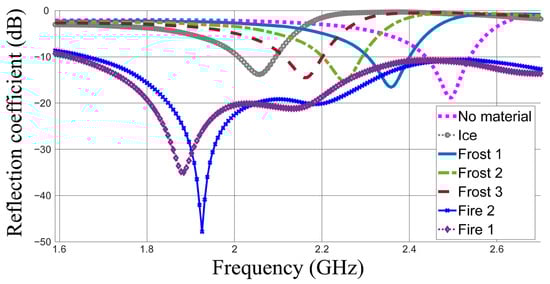
Figure 4.
The simulated reflection coefficients in dB for the investigated materials being detected.
This figure indicates that the resonant frequency shifts down from 2.496 GHz in the case without loading to 2.358, 2.25, 2.166, 2.058, 1.962 and 1.878 GHz in the cases of frost 1, frost 2, frost 3, ice, fire 2 (50 °C) and fire 1 (40 °C), respectively. In general, the resonant frequency shifts down with the dielectric constant. The sensitivity level is indicated as Δfr = 192 MHz per Δεr = 1 for the four materials of the same conductivity (frost 1, frost 2, frost 3 and ice). Howeverthe shift in the resonant frequency becomes smaller between the cases of water at 40 °C and 50 °C which is Δfr = 84 MHz for a dielectric constant difference of Δεr = 4.
In real cases, ice is expected to accumulate on the antenna surface. Hence, its accumulation effect is evaluated. Thicker accumulated layers are expected to shift the resonant frequency down since the effective permittivity increases with thickness. This shift can be justified with reference to Equation (3) as follows:
where in Hz is the resonant frequency after the antenna is loaded with the material under test, while in Hz is the resonant frequency of the antenna before loading with ice, frost or water. is the relative effective permittivity, which increases with thickness for the same material under test.
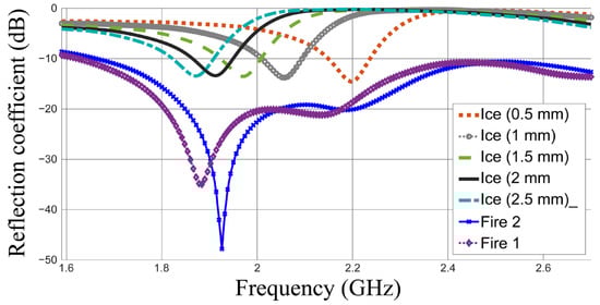
Figure 5.
The simulated reflection coefficients in dB for the different thicknesses of ice compared to those of wildfire-resembling cases.
Table 2.
Maximum radiation efficiency and gain of the materials under test.
The results clearly indicate that an ice thickness of 2 mm shifts the resonant frequency down to approximately 1.914 GHz.
Initial studies reveal that ice layers thicker than 1.5 mm may shift the resonant frequency down below 2 GHz, which is the same frequency range noted for fire 1 and fire 2. Consequently, a dual-property detection approach is employed, utilizing an additional property or frequency band to determine the detected material. This concept has been introduced in our previous work presented in [1] where an alternative frequency band was used for material identification. However, the matching level is employed as an additional decision parameter in this work. This is because a much deeper matching level attributed to the high conductivity values in the cases of fire 1 and fire 2 will probably always be obtained [35]. This property can be reliable enough, as much deeper matching will always be obtained for fire 1 and fire 2 if compared with that in the ice cases.
The reflection coefficients for ice thicknesses of 0.5, 1, 1.5, 2 and 2.5 mm are shown in Figure 5. The resonant frequencies at 0.5 and 1 mm thicknesses of ice are always above 2 GHz. However, the resonant frequencies when the ice thickness increases become close to those of fire. Hence, the matching property can be used in addition to the property of resonant frequency. When the resonant frequency falls below 2 GHz and S11 < −20 dB, fire can be detected. It is worth noting that the temperature considered for early detection and alarm purposes in early warning systems is 40 °C.
The results are influenced by the thickness of the material under test. A thicker layer results in larger effective permittivity, which produces a larger frequency shift and thus a higher sensitivity level, defined as (Δfr/Δεreff).
The effect of the internal loop on the sensitivity is investigated by studying the near electric field of the proposed antenna without loading and with frost (1 mm), ice (1 mm) and water at 40 °C. The results are depicted in Figure 6.
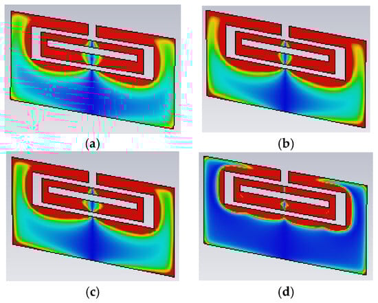
Figure 6.
The near electric field of the proposed antenna: (a) without loading, (b) frost 1, (c) ice (1 mm), (d) fire 1. Colors indicate the field strength in ascending order are as follows: Dark blue (weakest), light blue, green, yellow and red (strongest).
This figure shows that the near electric field is the strongest at the inner ring and at the edges between the inner and outer loops. Stronger coupling with the material under test is introduced when the near electric field is increased, which enhances the sensitivity as desired.
4.2. Data Transmission
The gain and radiation efficiency of the proposed antenna for all the investigated cases are summarized in Table 2.
A radiation efficiency approaching one was obtained when the antenna was not loaded with any material. A maximum 3 D gain of 2.83 dBi was obtained in this case. The radiation efficiency and gain decrease after loading the antenna with different materials. This is expected, as extra losses are introduced when the antenna is loaded with lossy materials such as ice, frost and wildfire. Ice and frost have small losses represented by their small conductivities, which are close to each other. Hence, their corresponding gain and radiation efficiency values are comparable to each other and to the no-loading case. On the other hand, large conductivity values and losses are encountered in the cases of fire 1 and fire 2. This is reflected on decreasing the radiation efficiency by 15 times and gain by around 11 dBi. The radiation pattern is omnidirectional, with maximum radiation obtained at the same angle for all cases under investigation, as shown in Figure 7.
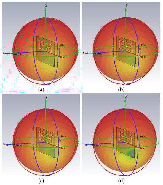
Figure 7.
The maximum 3D gain radiation patterns of the proposed antennas at 2.45 GHz for the following cases: (a) without loading, (b) frost 1 (c) ice (1 mm),and (d) fire 1; red: Maximum, yellow: medium and green: minimum.
The link budget is calculated for all cases of detection. The link parameters are summarized in Table 3 [36], and the results are summarized in Table 4.
Table 3.
The investigated link parameters.
Table 4.
Distance of communication of the investigated link.
The distance can be calculated with reference to Equation (4).
is a reference distance which is considered to be 1 m, f is the resonant frequency and is the velocity of electromagnetic waves in free space, which is equal to 3 × 10⁸ m/s.
Calculations are conducted for the frequencies obtained for each investigated MUT and their corresponding gain values. An input power of 20 dBm, receiver sensitivity of −89 dBm and receiving antenna gain of 14 dB [36] are assumed. A path loss exponent of three is used in the calculations considering a worst-outdoor-case scenario [24].
In general, a distance of longer than 300 m is always obtained for the antenna without loading and when loaded with ice or frost. This distance decreases to 157 m when loaded in the fire 1 case. This distance is sufficient to ensure reliable communication in real-world scenarios for the intended application.
The calculated distances are summarized in Table 4.
5. Validation and Discussion
The antenna is made of a conducting copper foil of 0.035 mm thickness and an approximate conductivity of (S/m) [37,38]. It has a substrate layer of LDPE (Low-Density Polyethylene) which has an approximate relative permittivity () of and a loss tangent ( of [39] at 2.45 GHz. The substrate has a thickness of 0.1 mm. The antenna is fed using a coaxial cable, as shown in Figure 8.
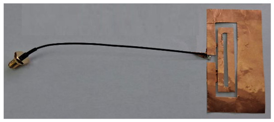
Figure 8.
The fabricated antenna.
The reflection coefficient (S11) was measured using an Anritsu ShockLine MS46322B two-port vector network analyzer (VNA), (Anritsu Company, Morgan Hill, CA, USA). The instrument has a frequency range from 100 MHz to 43.5 GHz, 130 microseconds per point sweep speed and better than 100 dB dynamic range to 43.5 GHz. It is operated in its standard S-parameter mode [40]. Calibration was performed using a SOLT (Short-Open-Load-Thru) kit; calibration standards were connected directly to the reference plane [41]. All measurements used a 50 Ω system impedance; cables with phase-stable 50 Ω coaxial connectors were used throughout. Additionally, care was taken to ensure that the connector did not contact any part of the material under test, avoiding unintended interactions in the measurements. A thin insulation layer is placed on the antenna surface between the antenna and ice. This is to isolate the ice’s effect from the coaxial cable and radiation from it. This layer is also made of LDPE and has a thickness of 0.1 mm. The proposed antenna loaded with ice for measurements is shown in Figure 9.
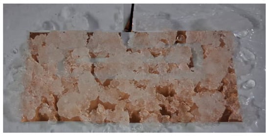
Figure 9.
The proposed antenna loaded with ice.
The measured results for the antenna without loading and with ice are presented in Figure 10. Two ice thicknesses of about 1 and 2 mm are used.
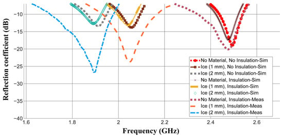
Figure 10.
The measured and simulated reflection coefficient S11 (dB) of the fabricated antenna without loading and with ice layers of 1 and 2 mm.
The measured results are compared with the following:
- -
- Simulated results without the insulation layer.
- -
- Simulated results with the insulation layer, taking into account its actual thickness and dielectric properties provided above.
This is to provide an accurate comparison by modeling the real measurement case more precisely while investigating the insulation layer effect at the same time.
It can be seen from this figure that adding the insulation layer causes the resonant frequency to shift down. The simulated resonant frequencies are shifted down by 12, 17 and 21 MHz for the cases with no material, ice (1 mm) and ice (2 mm), respectively, after placing this layer on top of the antenna. This is expected because of the larger effective permittivity introduced after adding this layer, which has a relative permittivity of 2.2. The simulation results, including the insulation layer, demonstrate better agreement with the measurement results. Only 2, 7 and 1 MHz are noted as differences between the simulated and measured results with the insulation layer for the cases with no material, ice (1 mm) and ice (2 mm), respectively. This is likely due to the non-uniform ice layer used in the measurements. Nonetheless, this difference is very small. A deeper −10 dB bandwidth is obtained during measurements. This is probably due to the additional losses introduced by the impurities of ice and the insulation layer, which were not included in the simulations [42]. Such losses cause larger power absorption rather than reflection, and hence deeper −10 dB matching is obtained. However, this deep −10 dB level was still within a range sufficient to differentiate between the distinct materials (ice, frost and wildfire) and detect them accurately. This can be further explained by referring to Table 5, which summarizes different detection cases based on both simulated and measured resonant frequency ranges and matching levels.
Table 5.
The detection cases based on frequency range and matching level.
Frost is always detected when a resonant frequency higher than 2.16 GHz is registered. An exception is noticed at 2.196 GHz in which an ice layer of a small thickness (0.5 mm) might be detected. However, this is acceptable, as frost can be considered a thin layer of ice [43]. In this case, precautions for frost damage can be taken when an alarm signal is received. Ice is always detected for a resonant frequency between 2 and 2.15 GHz. For frequencies below 2 GHz, ice can be detected at matching levels ranging from above −30 dB to −10 dB while wildfire can be detected at a deeper matching level, lower than −30 dB.
The proposed antenna is compared with other designs proposed in the literature for similar applications, with a summary provided in Table 6. The proposed antenna outperforms the design in [20] by obtaining a 7.72 dBi higher gain at an ice thickness of 1 mm only, although both designs are loops operating at the same frequency (2.45 GHz). This is attributed to the internal loop added to the proposed design. While the antennas in [1,19] exhibit higher gain values, this is expected as they operate at higher frequencies. The antenna in [5] achieved a slightly higher gain. However, a low sensitivity level was obtained for that design, with very small frequency shifts between the different tested materials.
Table 6.
Comparison with previous work.
The design in [44] utilized a double split-ring resonator to detect ice over a frequency range of 3.5 to 5 GHz. However, it was optimized and evaluated for sensing purposes rather than data transmission. The antenna in [45] was an RFID dipole optimized for ice detection at 915 MHz. Although it demonstrated good sensitivity, its received signal strength at 1 mm ice thickness was −59 dBm, which is 12 dBm lower than that of our design when used in the same system.
Regarding sensitivity, the proposed antenna is compared with others with documented data on frequency shifts for comparable materials and thicknesses. For example, the frequency shift obtained in [18] for ice was 36 MHz for a thickness of 1.5 cm. This is much smaller than the shift obtained for our design, which was 432 MHz for an ice thickness of 1 mm only. This ensures the design’s effectiveness in obtaining a high sensitivity level. The design in [1] obtained a frequency shift of 91 MHz only, which again indicates a low sensitivity level in comparison with the design proposed in this paper.
The contributions of this work can be summarized as follows:
- It involves a high sensitivity level combined with a relatively large gain compared to existing antennas of the same type operating at the same frequency.
- It proposes what is probably the first loop antenna proposed with a wide temperature detection range between 0 and 50 °C.
- It investigates and underscores the effect of multiple rings on the sensor loop antenna performance with the purpose of inspiring more optimized loop antenna structures for sensing applications in the future.
- It validates the robustness of flexible antennas for use in harsh environments, with applications in early warning systems and environmental monitoring.
6. Conclusions and Future Work
In this paper, a double rectangular ring loop antenna is designed and evaluated for the purposes of detecting ice, frost and water at temperatures of 40 °C and 50 °C, which resemble wildfire conditions. The antenna has shown a high level of sensitivity by responding with distinct resonant frequency shifts to different tested materials. A resonant frequency shift of 192 MHz was observed when the relative permittivity varied by only one for the four materials of the same conductivity (frost 1, frost 2, frost 3 and ice). This shift was 84 MHz between the cases of water at 40 °C and 50 °C. The matching level is also exploited in addition to the resonant frequency shift to distinguish the wildfire-resembling scenarios from ice layers thicker than 1.5 mm. The effect of the near electric field on the antenna sensitivity is investigated. The internal ring is found to increase the near-electric field strength and fine-tune the antenna performance. Additionally, calculations indicate that the antenna proposed in this work can send alarm signals over distances of 157 m for wildfire detection and 300 m for frost or ice detection. The antenna has shown robust performance with good matching between simulation and measurement results. It demonstrated robust performance when loaded with ice, maintaining consistent results in both simulations and measurements. The findings suggest that the multiple ring loop antenna is a promising candidate for sensing applications, offering a simple structure, excellent sensitivity, robust performance and relatively high gain compared to existing single loop antennas.
While the antenna has shown promising performance, further work should be conducted in the future. This includes the following:
- Further investigations on other contributing parameters such as smoke for wildfire detection and humidity may be needed in the future. This is to model the actual environment more accurately.
- Further work should investigate other loop and ring structures in addition to possible coupling techniques. For example, multiple split rings instead of a single ring may be investigated. The capabilities of the internal ring and split rings in strengthening the near electric field and boosting the sensitivity level may be studied.
- Measurements of the radiation efficiency, gain and radiation pattern should be conducted.
- Measurements over longer periods of time involving variations in the status of the material under test, which may include ice melting and temperature variations, should be conducted.
- Measurements after integration in a prototype sensing system should be conducted.
- Calculation and estimation of a more accurate link budget taking actual data rates and channel capacity into consideration should be conducted.
Funding
This research was funded by the North Atlantic Treaty Organization (NATO) Science for Peace and Security (SPS) Programme, with Manchester Metropolitan University (MMU) as the principal recipient of the award (Funder Reference: SPS G5932, Project Reference: WT 433209).
Data Availability Statement
The data presented in this study are available on request from the corresponding author.
Acknowledgments
We would like to thank the funder (North Atlantic Treaty Organization (NATO)/Science for Peace and Security (SPS)), as well as Mutah University in Jordan and the University of Liverpool in the UK for supporting this work.
Conflicts of Interest
The author declares no conflicts of interest.
References
- Alrawashdeh, R. A Cross-Shaped Slotted Patch Sensor Antenna for Ice and Frost Detection. Technologies 2025, 13, 5. [Google Scholar] [CrossRef]
- Huang, H. Antenna Sensors in Passive Wireless Sensing Systems. In Handbook of Antenna Technologies; Chen, Z., Liu, D., Nakano, H., Qing, X., Zwick, T., Eds.; Springer: Singapore, 2016. [Google Scholar]
- Islam, Z.U.; Bermak, A.; Wang, B. A Review of Microstrip Patch Antenna-Based Passive Sensors. Sensors 2024, 24, 6355. [Google Scholar] [CrossRef] [PubMed]
- Zhang, J.; Gao, C.; Li, Y.; Tan, J.; Xuan, F.; Ling, X. Flexible Multimode Antenna Sensor with Strain and Humidity Sensing Capability for Structural Health Monitoring. Sens. Actuators A Phys. 2022, 347, 113960. [Google Scholar] [CrossRef]
- Alam, T.; Chefena, M.; Rajo-Iglesias, E. Dual-Functional Communication and Sensing Antenna System. Sci. Rep. 2022, 12, 20387. [Google Scholar] [CrossRef]
- Zhang, T.; Ser, W. Robust Beam Pattern Synthesis for Antenna Arrays with Mutual Coupling Effect. IEEE Trans. Antennas Propag. 2011, 59, 2889–2895. [Google Scholar] [CrossRef]
- Liu, Y.; Shafai, L.; Isleifson, D.; Shafai, C. Split Ring Antennas and Their Application for Antenna Miniaturization. Sensors 2023, 23, 846. [Google Scholar] [CrossRef]
- Chi, K.-C.; Chen, S.-Y.; Hsu, P. Miniaturization of Slot Loop Antenna Using Split-Ring Resonators. In Proceedings of the 2009 IEEE Antennas and Propagation Society International Symposium (APSURSI), North Charleston, SC, USA, 1–5 June 2009; pp. 1–4. [Google Scholar]
- Qu, K.; Guo, S.; Ye, J.; Saeed, N. Near-Field Integrated Sensing and Communications: Unlocking Potentials and Shaping the Future. In Proceedings of the 2024 IEEE International Conference on Signal, Information and Data Processing (ICSIDP), Zhuhai, China, 22–24 November 2024; pp. 1–6. [Google Scholar]
- Albishi, A.M. A Novel Coupling Mechanism for CSRRs as Near-Field Dielectric Sensors. Sensors 2022, 22, 3313. [Google Scholar] [CrossRef]
- Handayani, A.S.; Pujiana, D.; Husni, N.L.; Amin, J.M.; Sitompul, C.R.; Taqwa, A.; Suroso; Soim, S. Robustness of Sensors Network in Environmental Monitoring. In Proceedings of the 2018 International Conference on Applied Science and Technology (iCAST), Manado, Indonesia, 26–27 October 2018; pp. 515–520. [Google Scholar]
- Alieldin, A.; El-Agamy, A.F.; Mowafy, M.; El-Akhdar, A.M. A Dual Circularly Polarized Omnidirectional Antenna for Radar-Warning Receiver. In Proceedings of the 2021 International Telecommunications Conference (ITC-Egypt), Alexandria, Egypt, 13–15 July 2021; pp. 1–4. [Google Scholar]
- Wang, W.; Xuan, X.-W.; Zhao, W.-Y.; Nie, H.-K. An Implantable Antenna Sensor for Medical Applications. IEEE Sens. J. 2021, 21, 14035–14042. [Google Scholar] [CrossRef]
- Yin, A.; Zhang, C.; Luo, J.; Liu, J.; Ren, Z.-Q.; Wang, Y.X.; Ye, Y.; Yin, R.; Feng, Q.; Chen, Y.Y.; et al. A Highly Sensitive and Miniaturized Wearable Antenna Based on MXene Films for Strain Sensing. Mater. Adv. 2022, 4, 917–922. [Google Scholar] [CrossRef]
- Elsheakh, D.N.; Mohamed, R.A.; Fahmy, O.M.; Ezzat, K.; Eldamak, A.R. Complete Breast Cancer Detection and Monitoring System by Using Microwave Textile-Based Antenna Sensors. Biosensors 2023, 13, 87. [Google Scholar] [CrossRef]
- Saghlatoon, H.; Mirzavand, R.; Honari, M.M.; Mousavi, P. Sensor Antenna Transmitter System for Material Detection in Wireless-Sensor-Node Applications. IEEE Sens. J. 2018, 18, 8812–8819. [Google Scholar] [CrossRef]
- Belghiti, M.K.; El Gibari, M.; Rhallabi, A.; El Fallah Serghrouchni, A. Development and Optimization of Gas Sensors for Ammonia detection. In Proceedings of the 2024 32nd Telecommunications Forum (TELFOR), Belgrade, Serbia, 26–27 November 2024; pp. 1–3. [Google Scholar]
- Kozak, R.; Khorsand, K.; Zarifi, T.; Golovin, K.; Zarifi, M.H. Patch Antenna Sensor for Wireless Ice and Frost Detection. Sci. Rep. 2021, 11, 13707. [Google Scholar] [CrossRef] [PubMed]
- Altakhaineh, A.T.; Alrawashdeh, R.; Zhou, J. Machine Learning-Aided Dual-Function Microfluidic SIW Sensor Antenna for Frost and Wildfire Detection Applications. Energies 2024, 17, 5208. [Google Scholar] [CrossRef]
- Wagih, M.; Shi, J. Toward the Optimal Antenna-Based Wireless Sensing Strategy: An Ice Sensing Case Study. IEEE Open J. Antennas Propag. 2022, 3, 687–699. [Google Scholar] [CrossRef]
- Alrawashdeh, R. A Wearable Finger-Ring Antenna for Smart-Home Internet of Things. Przegląd Elektrotechniczny 2024, 100, 256–259. [Google Scholar] [CrossRef]
- Li, R.-L.; Fusco, V.F.; Nakano, H. Circularly Polarized Open-Loop Antenna. IEEE Trans. Antennas Propag. 2003, 51, 2475–2477. [Google Scholar]
- Tarawneh, A. A Triple Band Flexible Antenna Based on Asymmetric Spiral Split Rings Coupled to External Loop. Jordan J. Energy 2024, 2, 1–16. [Google Scholar] [CrossRef]
- Alrawashdeh, R.; Huang, Y.; Kod, M.; Sajak, A.A.B. A Broadband Flexible Implantable Loop Antenna with Complementary Split Ring Resonators. IEEE Antennas Wirel. Propag. Lett. 2015, 14, 1506–1509. [Google Scholar] [CrossRef]
- Huang, H. Flexible Wireless Antenna Sensor: A Review. IEEE Sens. J. 2013, 13, 3865–3872. [Google Scholar] [CrossRef]
- Hayt, W.; Kemmerly, J.; Durbin, S. Engineering Circuit Analysis; McGraw-Hill: New York, NY, USA, 2012. [Google Scholar]
- Sedra, A.S.; Smith, K.C. Microelectronic Circuits, 8th ed.; Oxford University Press: Oxford, UK, 2020. [Google Scholar]
- Emerson Process Management. Impact of Weather on Smart Wireless Networks. 2010. Available online: https://www.emerson.com/documents/automation/white-paper-impact-of-weather-on-smart-wireless-networks-en-42650.pdf (accessed on 13 December 2025).
- Huang, Y.; Boyle, K. Antennas: From Theory to Practice; John Wiley & Sons Ltd.: Chichester, UK, 2008. [Google Scholar]
- Glen, J.W.; Paren, J.G. The Electrical Properties of Snow and Ice. J. Glaciol. 1975, 15, 15–38. [Google Scholar] [CrossRef][Green Version]
- Matzler, C. Microwave Permittivity of Dry Snow. IEEE Trans. Geosci. Remote Sens. 1996, 34, 573–581. [Google Scholar] [CrossRef]
- Vijay, R.; Jain, R.; Sharma, K.S. Dielectric Properties of Water at Microwave Frequencies. Int. J. Eng. Res. Technol. (IJERT) 2015, 3, 1–3. [Google Scholar]
- Hufford, G. A Model for the Complex Permittivity of ice at Frequencies Below 1 THz. Int. J. Infrared Millim. Waves 1991, 12, 677–682. [Google Scholar] [CrossRef]
- CST—Computer Simulation Technology. CST Studio Suite, Version 2024; Dassault Systèmes: Darmstadt, Germany, 2024.
- Alrawashdeh, R.S.; Alharazneh, F.; Alsarayreh, F.; Aladaileh, E. A Novel Flexible Cloud Shape Loop Antenna for Muscle Implantable Devices. Jordan J. Electr. Eng. 2019, 5, 61–76. [Google Scholar]
- Pietrosemoli, E.; Zennaro, M. Link Budget Calculation, PowerPoint Presentation. Available online: https://www.internetsociety.org/wp-content/uploads/2017/10/Link-Budget-Calculation.pdf (accessed on 12 December 2025).
- RS PRO Copper Foil Shielding Tape 19 mm × 33 m Datasheet. Available online: https://docs.rs-online.com/c965/0900766b8170b009.pdf (accessed on 12 December 2025).
- Fine Metals Corporation. Copper Foil. Available online: https://finemetalscorp.com/product/copper-foil/ (accessed on 12 December 2025).
- Chao, H.-W.; Chen, H.-H.; Chang, T.-H. Measuring the Complex Permittivity of Plastics in Irregular Shapes. Polymers 2021, 13, 2658. [Google Scholar] [CrossRef] [PubMed]
- Anritsu Corporation. Economy Vector Network Analyzer MS46322B. Available online: https://www.anritsu.com/en-us/test-measurement/products/ms46322b (accessed on 12 December 2025).
- Anritsu ShockLine. ShockLine MS46122A/B, MS46131A, ME786xA, and MS46322A/B Series Vector Network Analyzer. In Calibration and Measurement Guide; Anritsu Company: Morgan Hill, CA, USA, 2023; Available online: https://dl.cdn-anritsu.com/en-us/test-measurement/files/Manuals/Measurement-Guide/10410-00336V.pdf (accessed on 12 December 2025).
- Matzler, C.; Wegmuller, U. Dielectric Properties of Fresh-Water Ice at Microwave Frequencies. J. Phys. D Appl. Phys. 1987, 20, 1623–1630. [Google Scholar] [CrossRef]
- Spadaccia, S.; Patty, C.H.L.; Thomas, N.; Pommerol, A. Experimental Study of Frost Detectability on Planetary Surfaces Using Multicolor Photometry and Polarimetry. Icarus 2023, 396, 115503. [Google Scholar] [CrossRef]
- Wiltshire, B.; Mirshahidi, K.; Golovin, K.; Zarifi, M.H. Robust and sensitive frost and ice detection via planar microwave resonator sensor. Sens. Actuators B Chem. 2019, 301, 126881. [Google Scholar] [CrossRef]
- Wagih, M.; Shi, J. Complex-Impedance Dipole Antennas as RFID-Enabled Ice Monitors. In Proceedings of the 2021 IEEE International Symposium on Antennas and Propagation and USNC-URSI Radio Science Meeting (APS/URSI), Singapore, 4–10 December 2021; pp. 399–400. [Google Scholar]


Disclaimer/Publisher’s Note: The statements, opinions and data contained in all publications are solely those of the individual author(s) and contributor(s) and not of MDPI and/or the editor(s). MDPI and/or the editor(s) disclaim responsibility for any injury to people or property resulting from any ideas, methods, instructions or products referred to in the content. |
© 2025 by the author. Licensee MDPI, Basel, Switzerland. This article is an open access article distributed under the terms and conditions of the Creative Commons Attribution (CC BY) license.