
The Research on Path Planning Method for Detecting Automotive Steering Knuckles Based on Phased Array Ultrasound Point Cloud

 , ,
, ,
Abstract
1. Introduction
2. Working Principle
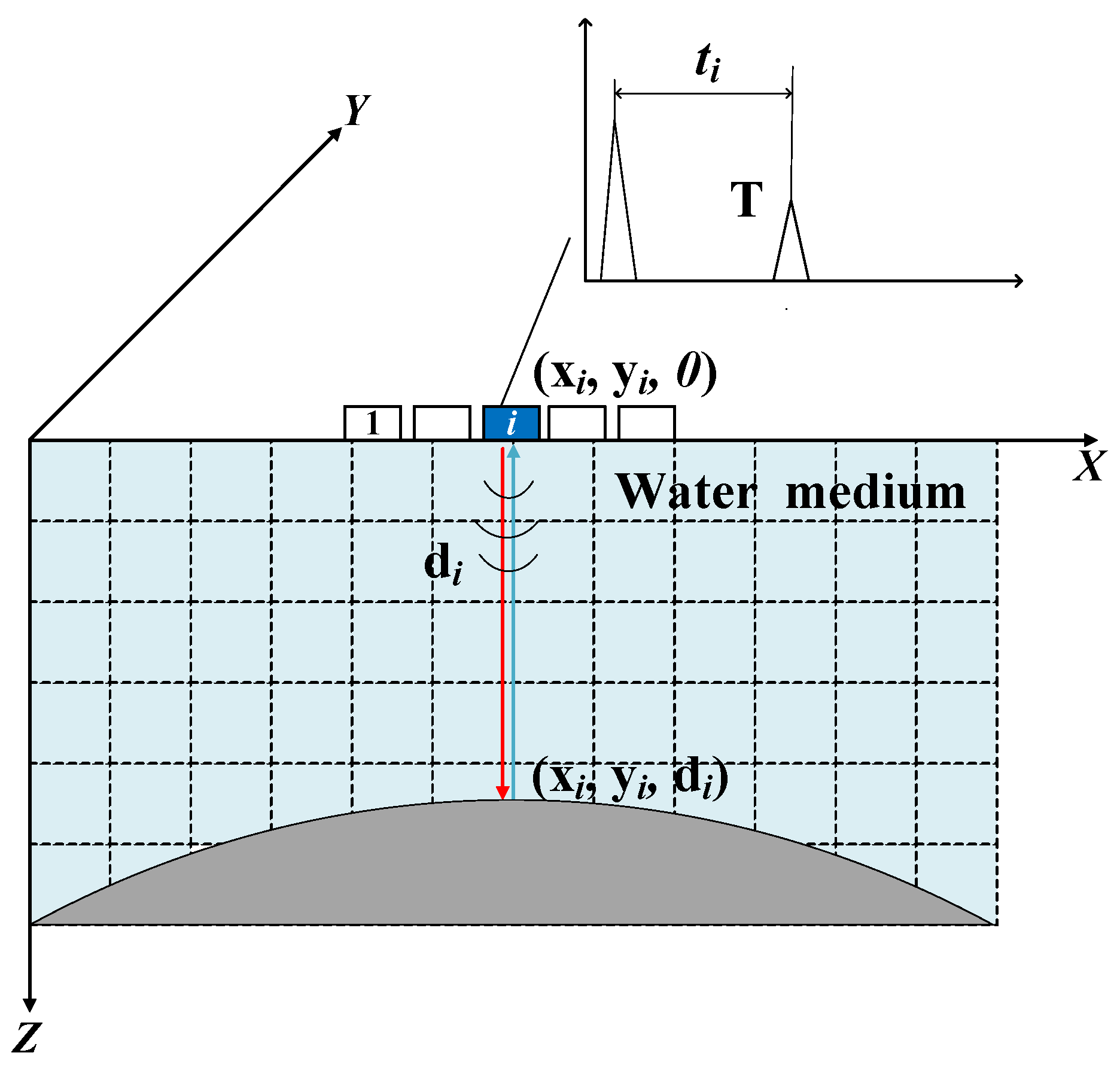
2.1. Phased Array Ultrasonic Point Cloud Acquisition
2.2. Point Cloud Segmentation
- (1)
- Determine the slicing direction: Different slicing directions directly affect the shape of the curve in the slicing plane. This paper uses radial slicing, where the constructed planes are evenly distributed radially along the workpiece and parallel to the central axis of the point cloud;
- (2)
- Determine the slicing thickness : The choice of slicing thickness is crucial. If is too large, the fitted curve will deviate from the actual surface contour of the workpiece, affecting path accuracy. If is too small, it may not fully represent the workpiece’s surface shape, potentially leading to overfitting of the path;
- (3)
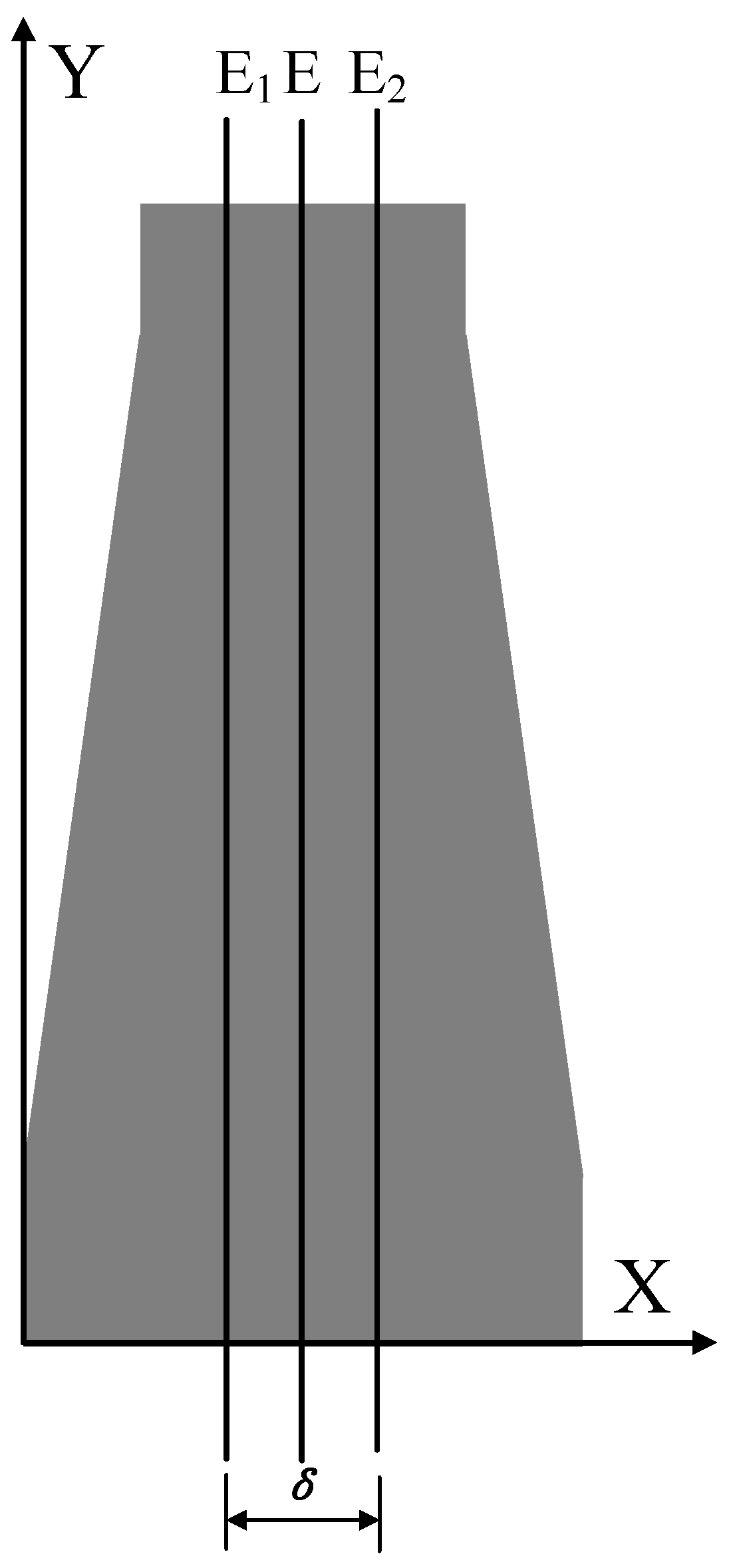
- Point cloud segmentation: In the point cloud segmentation process, a coordinate system is established with the slicing direction as the x-axis, and the slicing space is divided. By setting boundary planes and , the point cloud satisfying is selected, forming a point cloud dataset that contains all point data within the slicing space. This reduces the point cloud classification problem from three dimensions to one dimension, improving classification efficiency;
- (4)
- Distinguish the upper and lower parts: Since the point cloud in this paper is shaft-shaped, the segmented point cloud will have two parts: upper and lower. The points belonging to the upper or lower part can be distinguished by comparing the Z coordinate of each point with the Z coordinate of the central axis. If , the point belongs to the upper part; if , the point belongs to the lower part.
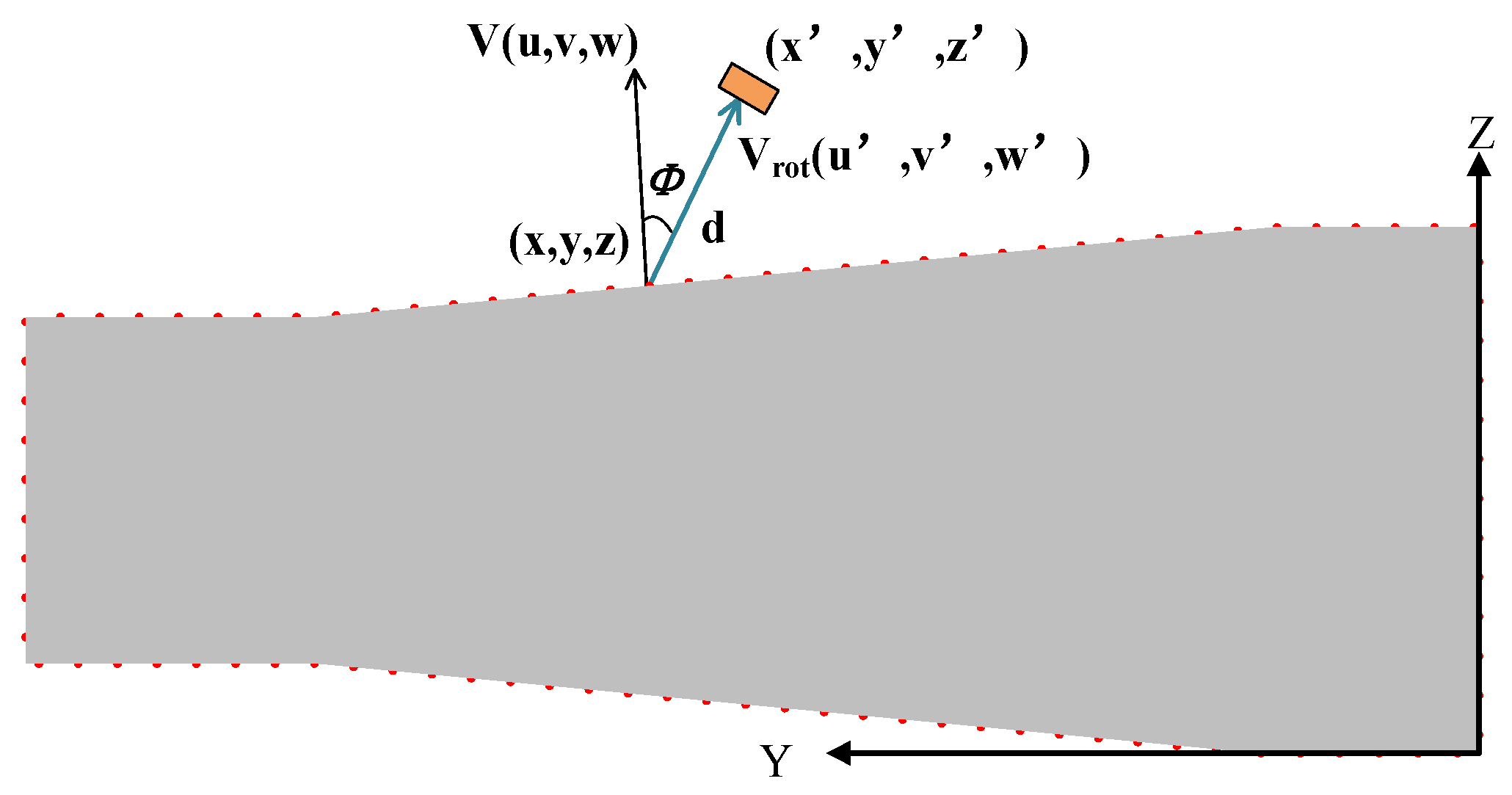
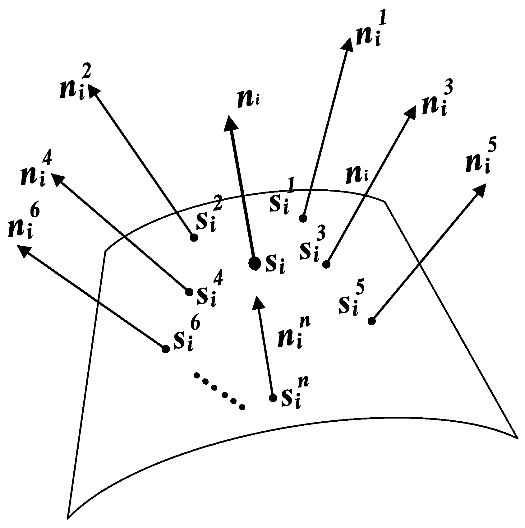
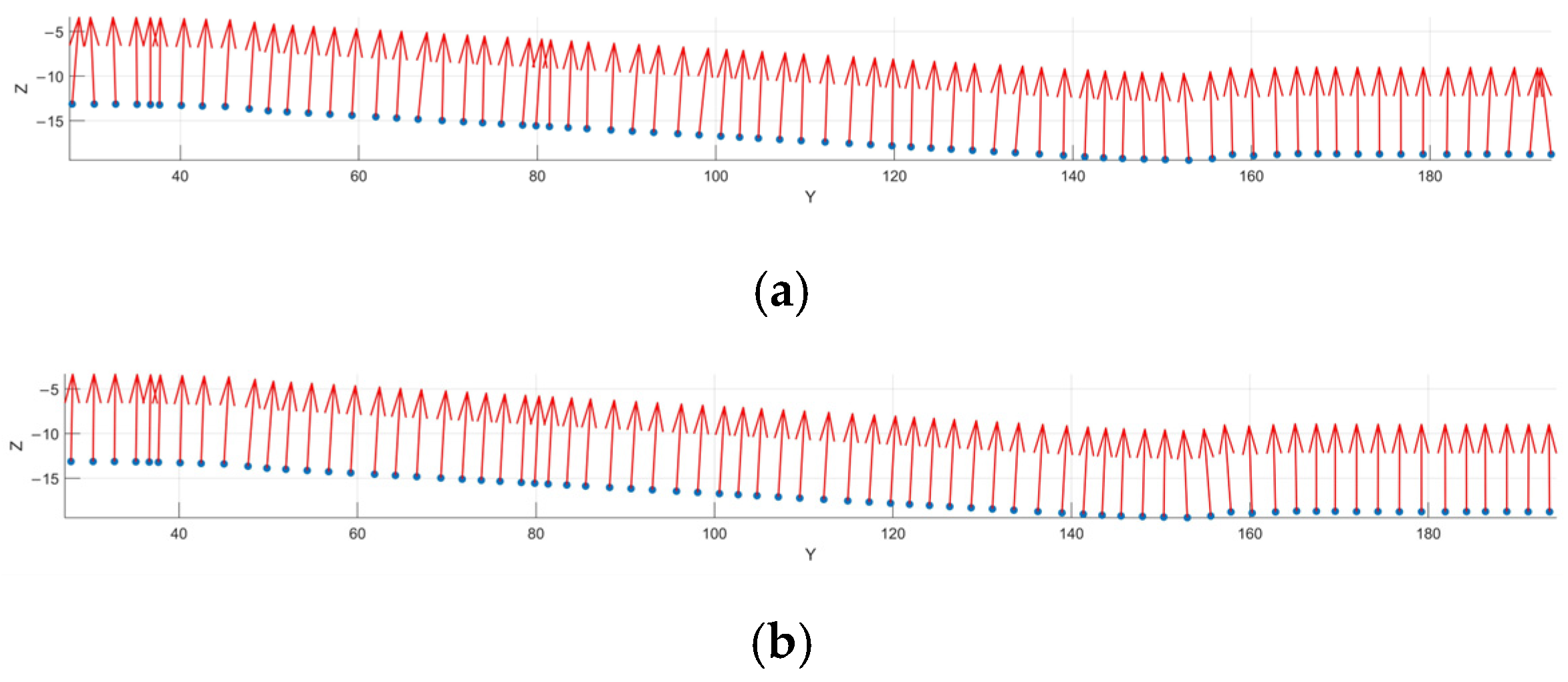
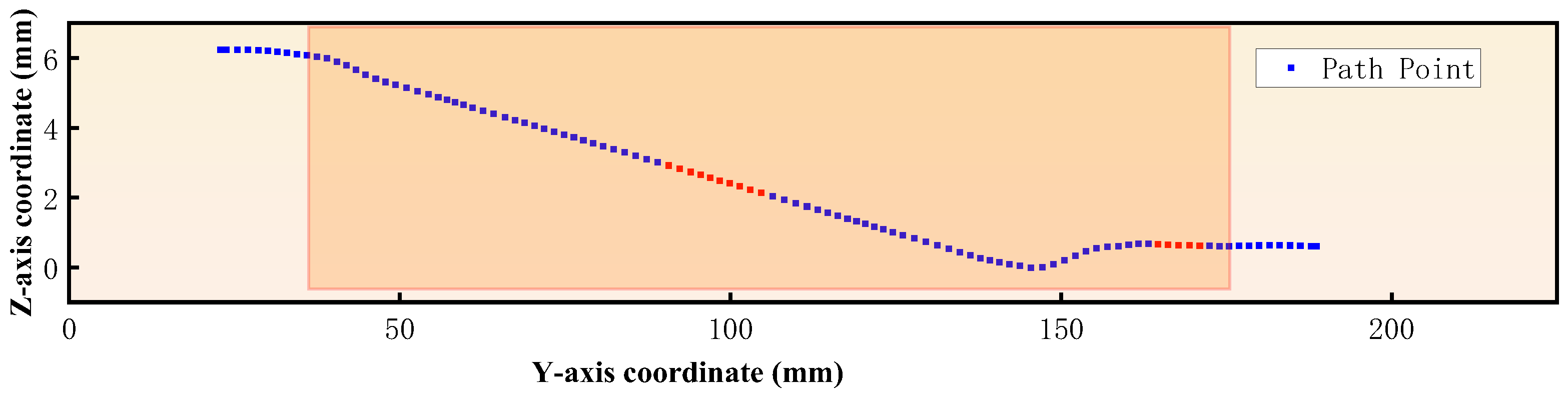
2.3. Automatic Scanning Path Planning Based on Ultrasonic Point Cloud
2.4. Path Optimization Based on Cubic Hermite Interpolation
2.5. Path Planning Steps
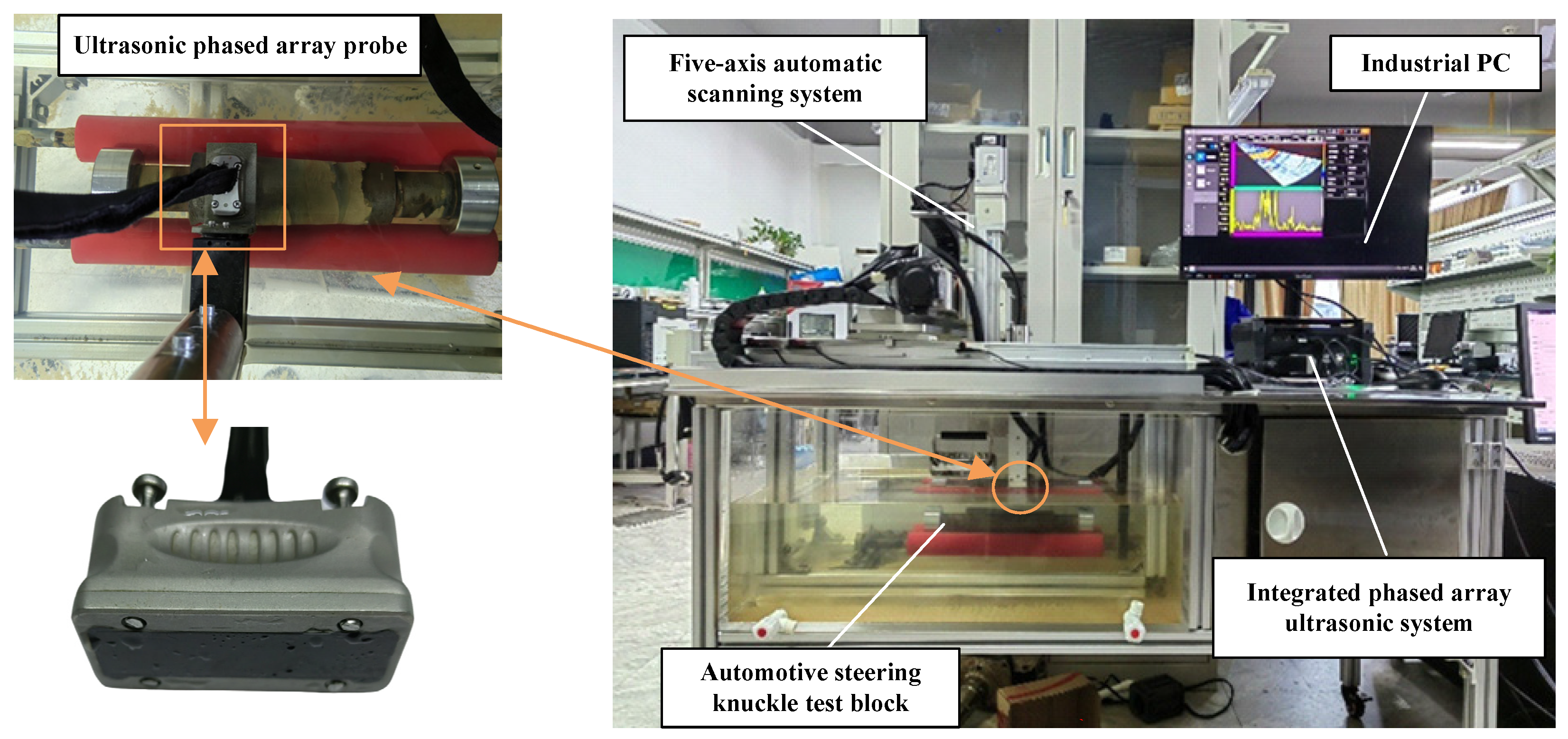
3. Experimental Configuration
- (1)
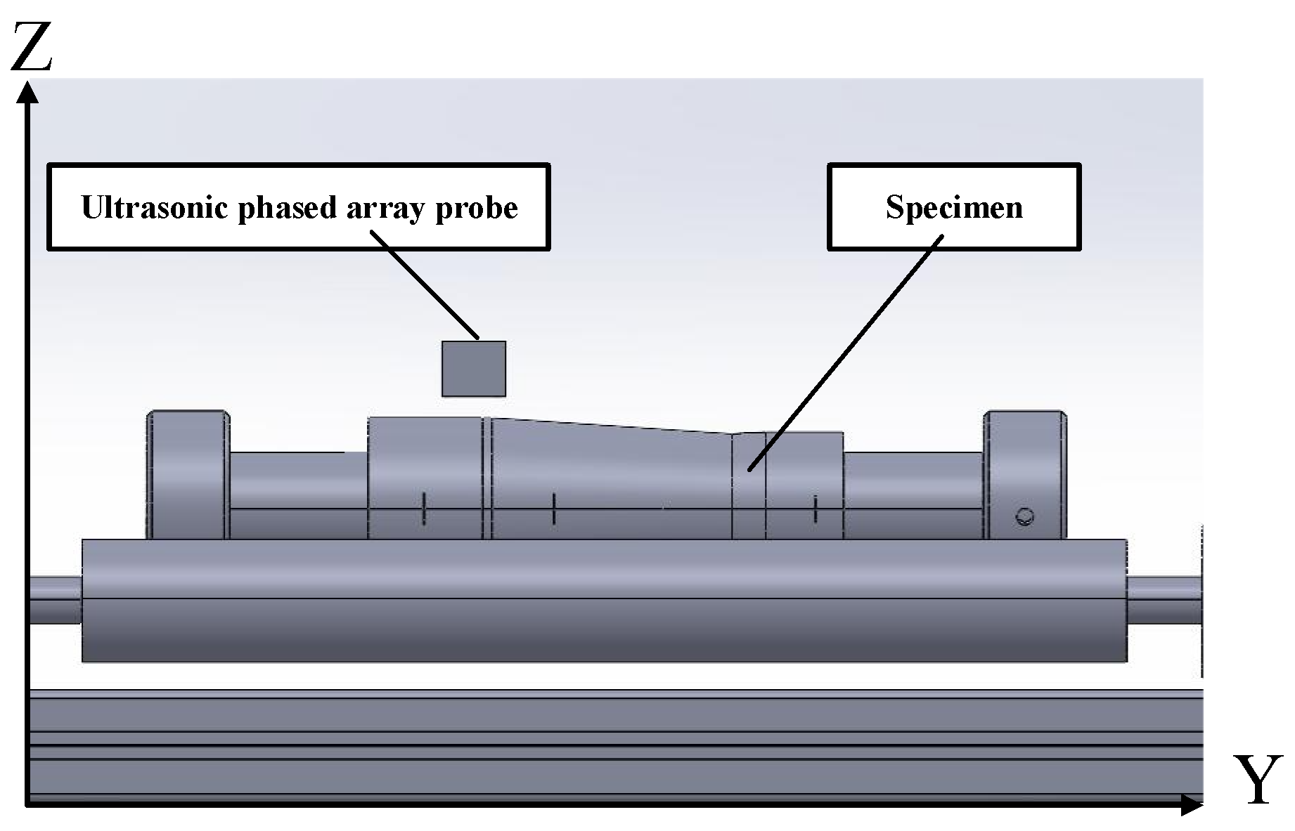
- Point cloud data acquisition: The dimensions of the steering knuckle and motion parameters are input. The motion control card transmits parameters such as scanning mode, speed, and range to the servo motor driver. The Y-axis servo motor drives the probe to perform axial step scanning on the steering knuckle, while the workpiece rotary motor drives the workpiece to perform step rotational movement. Both axes work in coordination to complete the scanning task of the workpiece;
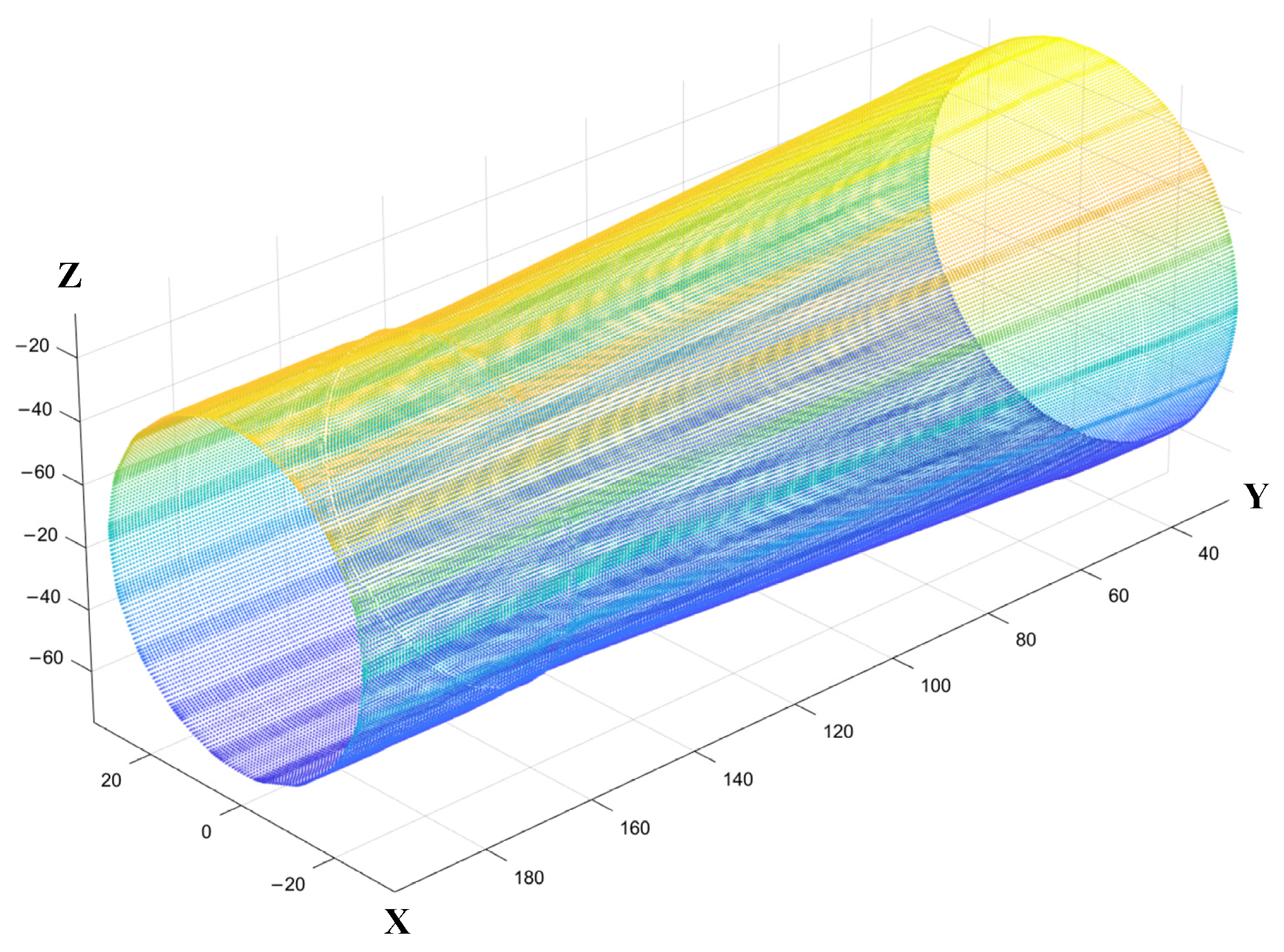
- (2)
- Point cloud data collection of the steering knuckle: During the collection of point cloud data, the multi-axis motion control card transmits the current actual position of the probe in real-time to the upper computer’s data acquisition software. When the predetermined position is reached, ultrasonic A-scan data are collected. The pre-processed inspection data and position information are processed by the point cloud collection software to generate the point cloud image and save the point cloud data;
- (3)
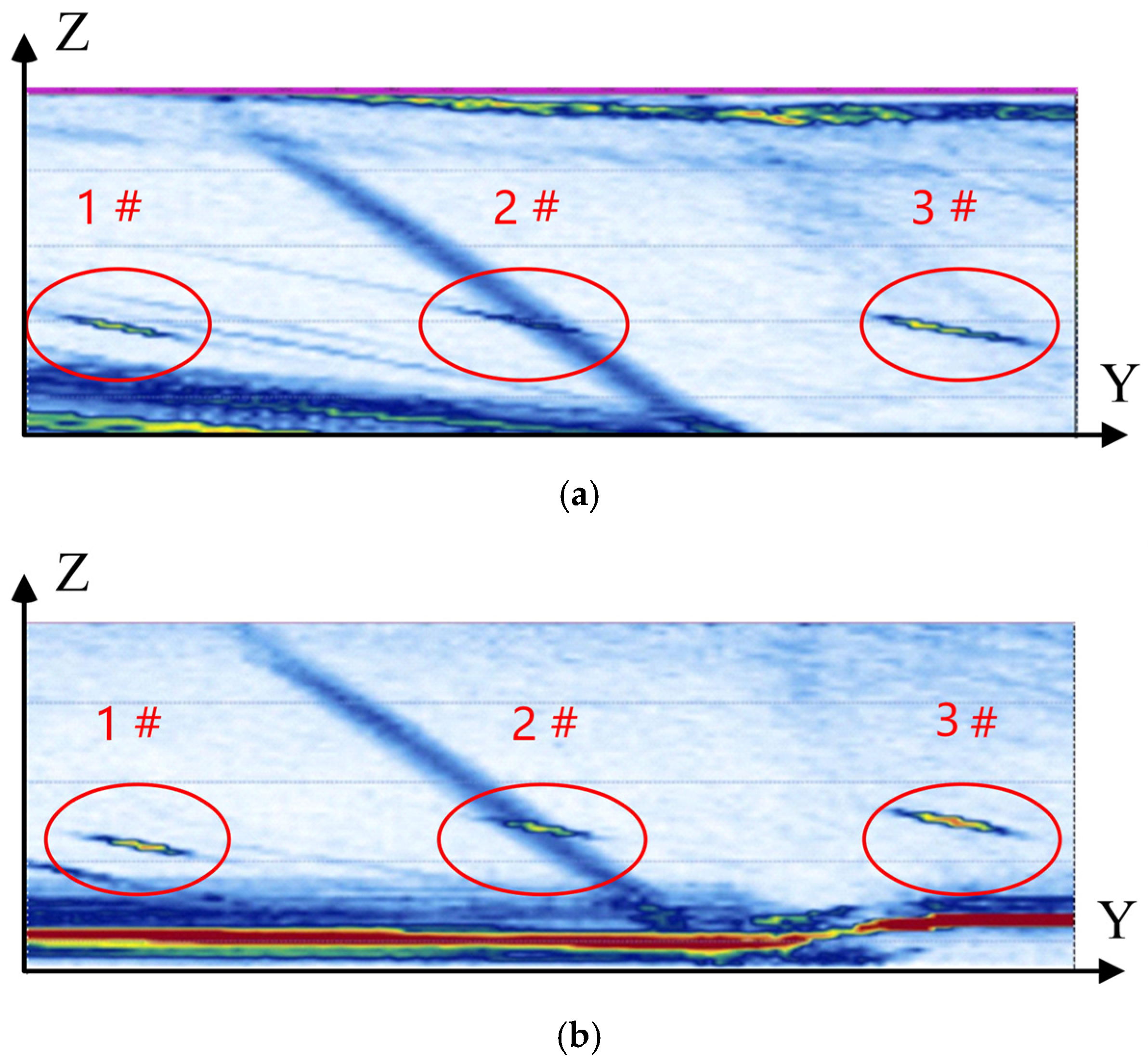
- Automatic path generation and inspection: The probe pose information of each point on the scanning path is input into the upper computer software of the automatic scanning system to complete the automated path scanning. During the execution, the probe collects ultrasonic A-scan signals and transmits the A-scan signals along with the position information in real time to the upper computer’s imaging software. After processing, B-scan images are generated.
4. Experimental Verification and Analysis
5. Discussion
6. Conclusions
Author Contributions
Funding
Institutional Review Board Statement
Informed Consent Statement
Data Availability Statement
Conflicts of Interest
References
- Reza Kashyzadeh, K. Effects of Axial and Multiaxial Variable Amplitude Loading Conditions on the Fatigue Life Assessment of Automotive Steering Knuckle. J. Fail. Anal. Prev. 2020, 20, 455–463. [Google Scholar] [CrossRef]
- Lyu, D.; Li, X.; Zhang, R.; Zhang, S. Ultrasonic measurement model-based non-destructive detection method for curved components using an immersion spherically focused transducer. Nondestruct. Test. Eval. 2022, 37, 184–202. [Google Scholar] [CrossRef]
- Wang, G.; Liao, T.W. Automatic identification of different types of welding defects in radiographic images. Ndt E Int. 2002, 35, 519–528. [Google Scholar] [CrossRef]
- García-Martín, J.; Gómez-Gil, J.; Vázquez-Sánchez, E. Non-destructive techniques based on eddy current testing. Sensors 2011, 11, 2525–2565. [Google Scholar] [CrossRef]
- Zolfaghari, A.; Zolfaghari, A.; Kolahan, F. Reliability and sensitivity of magnetic particle nondestructive testing in detecting the surface cracks of welded components. Nondestruct. Test. Eval. 2018, 33, 290–300. [Google Scholar] [CrossRef]
- Xu, G.; Guan, X.; Qiao, Y.; Gao, Y. Analysis and Innovation for Penetrant Testing for Airplane Parts. Procedia Eng. 2015, 99, 1438–1442. [Google Scholar]
- Bolotina, I.; Dyakina, M.; Kröning, M.; Mohr, F.; Reddy, K.M.; Soldatov, A.; Zhantlessov, Y. Ultrasonic arrays for quantitative nondestructive testing an engineering approach. Russ. J. Nondestruct. Test. 2013, 49, 145–158. [Google Scholar] [CrossRef]
- Pan, L.; Dong, S.-Y.; Xu, B.-S.; Liu, B. The Review of Study and Application of Phased Array Ultrasonic Testing Tecnology. Nondestruct. Test. 2013, 35, 26–29. [Google Scholar]
- Nanekar, P.; Kumar, A.; Jayakumar, T. SAFT-assisted sound beam focusing using phased arrays (PA-SAFT) for non-destructive evaluation. Nondestruct. Test. Eval. 2015, 30, 105–123. [Google Scholar] [CrossRef]
- Xu, N.; Zhou, Z. Numerical simulation and experiment for inspection of corner-shaped components using ultrasonic phased array. NDT E Int. 2014, 63, 28–34. [Google Scholar] [CrossRef]
- Kang, S.H.; Kang, M.; Kang, L.H. Defect detection on the curved surface of a wind turbine blade using piezoelectric flexible line sensors. Struct. Health Monit. 2022, 21, 1207–1217. [Google Scholar] [CrossRef]
- Hu, H.; Zhu, X.; Wang, C.; Zhang, L.; Li, X.; Lee, S.; Huang, Z.; Chen, R.; Chen, Z.; Wang, C.; et al. Stretchable ultrasonic transducer arrays for three-dimensional imaging on complex surfaces. Sci. Adv. 2018, 4, eaar3979. [Google Scholar] [CrossRef]
- Cao, J.; Fei, Q.; Jiang, L.; Li, X.; Yan, J.; Ding, H. Adaptive probe position correction for automated complex weld inspection based on structural signal monitoring. Nondestruct. Test. Eval. 2024, 1–21. [Google Scholar] [CrossRef]
- Li, X.B.; Hu, H.W.; Yang, Y.; Ni, P.-J.; Yang, C. Automatic ultrasonic inspection of flaws in a propeller-blade. Nondestruct. Test. Eval. 2010, 25, 341–351. [Google Scholar] [CrossRef]
- Mineo, C.; Pierce, S.G.; Nicholson, P.I.; Cooper, I. Robotic path planning for non-destructive testing—A custom MATLAB toolbox approach. Robot. Comput.-Integr. Manuf. 2016, 37, 1–12. [Google Scholar] [CrossRef]
- Bogue, R. The role of robotics in non-destructive testing. Ind. Robot. 2013, 37, 421–426. [Google Scholar] [CrossRef]
- Mineo, C.; Pierce, S.G.; Wright, B.; Cooper, I.; Nicholson, P. PAUT inspection of complex-shaped composite materials through six DOFs robotic manipulators. Insight-Non-Destr. Test. Cond. Monit. 2015, 57, 161–166. [Google Scholar] [CrossRef]
- Sattar, T.P.; Brenner, A.A. Robotic system for inspection of test objects with unknown geometry using NDT methods. Ind. Robot 2009, 36, 340–343. [Google Scholar] [CrossRef]
- Guan, S.; Hua, L.; Wang, X.; Zheng, G. Ultrasonic TFM imaging inspection of large complex rings using defect quantitative evaluation mappings. Nondestruct. Test. Eval. 2024, 1–22. [Google Scholar] [CrossRef]
- Luk, B.L.; Liu, K.P.; Jiang, Z.D.; Tong, F. Robotic impact-acoustics system for tile-wall bonding integrity inspection. Mechatronics 2009, 19, 1251–1260. [Google Scholar] [CrossRef]
- Pan, Q.; Shao, C.; Xiao, D.; Pan, R.; Liu, X.; Song, W. Robotic Ultrasonic Measurement of Residual Stress in Complex Curved Surface Components. Appl. Bionics Biomech. 2019, 2019, 2797896. [Google Scholar] [CrossRef]
- Mineo, C.; Pierce, S.G.; Wright, B.; Nicholson, P.I.; Cooper, I. Robotic path planning for non-destructive testing of complex shaped surfaces. Am. Inst. Phys. 2015, 1650, 1977–1987. [Google Scholar] [CrossRef]
- Zhen, X.; Yong, Y.; Chunguang, X.; Fang, L.F.; Liang, L.X. Profile tracking with ultrasonic alignment for automatic Non-destructive testing of complex structures. Robot. Comput.-Integr. Manuf. 2018, 49, 134–142. [Google Scholar] [CrossRef]
- Li, F.; Yao, A.; Zhu, L.M.; Yang, C.; Zhang, Y. An Accelerated Post-processing Calculation Method of Curved Surface Profile Extraction Based on the Total Focusing Method of Ultrasonic Phased Array. J. Phys. Conf. Series 2022, 2242, 012001. [Google Scholar] [CrossRef]
- Riise, J.; Mineo, C.; Pierce, S.G.; Nicholson, P.I.; Cooper, I. Adapting robot paths for automated NDT of complex structures using ultrasonic alignment. In Proceedings of the 45th Annual Review of Progress in Quantitative Nondestructive Evaluation, Portland, Oregon, 14–18 July 2019; Volume 38. [Google Scholar] [CrossRef]
- Matuda, M.Y.; Buiochi, F.; Adamowski, J.C. Experimental analysis of surface detection methods for two-medium imaging with a linear ultrasonic array. Ultrasonics 2019, 94, 50–59. [Google Scholar] [CrossRef]
- Robert, S.; Calmon, P.; Calvo, M.; Le Jeune, L.; Iakovleva, E. Surface estimation methods with phased-arrays for adaptive ultrasonic imaging in complex components. AIP Conf. Proc. 2015, 1650, 1657–1666. [Google Scholar]
- Camacho, J.; Cruza, J.F.; Brizuela, J.; Fritsch, C. Automatic dynamic depth focusing for NDT. IEEE Trans. Ultrason. Ferroelectr. Freq. Control 2014, 61, 673–684. [Google Scholar] [CrossRef]
- Valdenebro, A.G. Visualizing Rotations and Composition of Rotations with Rodrigues’ Vector. Eur. J. Phys. 2016, 37, 065001. [Google Scholar] [CrossRef]
- Sanchez, J.; Denis, F.; Coeurjolly, D.; Dupont, F.; Trassoudaine, L.; Checchin, P. Robust normal vector estimation in 3D point clouds through iterative principal component analysis. ISPRS J. Photogramm. Remote Sens. 2020, 163, 18–35. [Google Scholar] [CrossRef]
- Ben-Shabat, Y.; Lindenbaum, M.; Fischer, A. Nesti-net: Normal estimation for unstructured 3d point clouds using convolutional neural networks. In Proceedings of the IEEE/CVF Conference on Computer Vision and Pattern Recognition, Long Beach, CA, USA, 15–20 June 2019; pp. 10112–10120. [Google Scholar]
- Nurunnabi, A.; West, G.; Belton, D. Outlier detection and robust normal-curvature estimation in mobile laser scanning 3D point cloud data. Pattern Recognit. 2015, 48, 1404–1419. [Google Scholar] [CrossRef]
- Zhang, H.; Xu, C.; Xiao, D. Offline correction of tool path deviations for robot-assisted ultrasonic nondestructive testing. Proc. Inst. Mech. Eng. Part C J. Mech. Eng. Sci. 2019, 233, 2879–2893. [Google Scholar] [CrossRef]
- Bentley, J.L. Multidimensional binary search trees used for associative searching. Commun. ACM 1975, 18, 509–517. [Google Scholar] [CrossRef]
- Yang, J.; Aslan, D.; Altintas, Y. A feedrate scheduling algorithm to constrain tool tip position and tool orientation errors of five-axis CNC machining under cutting load disturbances. CIRP J. Manuf. Sci. Technol. 2018, 23, 78–90. [Google Scholar] [CrossRef]


| Components | Vendor | Parameters |
|---|---|---|
| Integrated Phased Array Ultrasonic System | Eintik | Sampling frequency: 100 MHz |
| Phased Array Ultrasonic Probe | Eintik | 64 elements, center frequency 10 MHz; center-to-center distance 0.6 mm; element width 0.5 mm |
| Three-Axis Gantry Sliding Table | Leading Technology | XYZ Travel: 600, 1000, 400 mm; max speed: 500 mm/s; positioning accuracy: 0.01 mm |
| Probe Rotation Mechanism | Self-made | Minimum controllable angle: 0.1°; rotation axes: X |
| Workpieces Rotation Mechanism | Self-made | Minimum controllable angle: 0.1°; rotation axes: Y |
| Point | Point Cloud Axial Diameter (mm) | Actual Axial Diameter (mm) | Absolute Error (mm) | Relative Error |
|---|---|---|---|---|
| 1# | 64.65 | 65 | 0.35 | 0.54% |
| 2# | 58.76 | 59.41 | 0.65 | 1.09% |
| 3# | 54.42 | 55.16 | 0.74 | 1.34% |
| 1 | 64.70 | 65 | 0.30 | 0.47% |
| 2 | 64.64 | 65 | 0.36 | 0.56% |
| 3 | 64.05 | 64.31 | 0.26 | 0.41% |
| 4 | 62.52 | 62.73 | 0.21 | 0.34% |
| 5 | 61.38 | 62.07 | 0.69 | 1.12% |
| 6 | 60.25 | 61 | 0.75 | 1.24% |
| 7 | 59.18 | 60 | 0.82 | 1.38% |
| 8 | 58.05 | 58.55 | 0.50 | 0.87% |
| 9 | 56.96 | 57.63 | 0.67 | 1.18% |
| 10 | 55.93 | 56.22 | 0.28 | 0.50% |
| 11 | 54.95 | 55.68 | 0.72 | 1.31% |
| 12 | 53.85 | 54.55 | 0.70 | 1.34% |
| 13 | 53.64 | 53.71 | 0.07 | 0.14% |
| 14 | 53.47 | 53.71 | 0.24 | 0.45% |
| 15 | 53.78 | 54.5 | 0.72 | 1.32% |
| 16 | 54.23 | 54.5 | 0.27 | 0.50% |
| 17 | 54.17 | 54.5 | 0.33 | 0.62% |
| 18 | 53.83 | 54.5 | 0.67 | 1.24% |
| Point | Coordinates | Attitude Vector | Calculated Angle | Theoretical Angle | Error |
|---|---|---|---|---|---|
| 1 | (0, 90.67, 2.92) | (0, 0.3451, 0.9385) | 20.19° | 19.7° | 0.49° |
| 2 | (0, 92.34, 2.82) | (0, 0.3452, 0.9385) | 20.19° | 19.7° | 0.49° |
| 3 | (0, 93.96, 2.73) | (0, 0.3452, 0.9385) | 20.18° | 19.7° | 0.48° |
| 4 | (0, 95.48, 2.65) | (0, 0.3451, 0.9385) | 20.19° | 19.7° | 0.49° |
| 5 | (0, 96.94, 2.57) | (0, 0.3451, 0.9385) | 20.19° | 19.7° | 0.49° |
| 6 | (0, 98.40, 24.89) | (0, 0.3449, 0.9386) | 20.17° | 19.7° | 0.47° |
| 7 | (0, 99.85, 2.41) | (0, 0.3446, 0.9387) | 20.16° | 19.7° | 0.46° |
| 8 | (0, 101.35, 2.32) | (0, 0.3444, 0.9389) | 20.14° | 19.7° | 0.44° |
| 9 | (0, 102.95, 2.23) | (0, 0.3435, 0.9391) | 20.09° | 19.7° | 0.39° |
| 10 | (0, 104.64, 2.14) | (0, 0.3451, 0.9385) | 20.19° | 19.7° | 0.49° |
| 11 | (0, 164.66, 0.66) | (0, 0.2866, 0.9580) | 16.88° | 17° | −0.12° |
| 12 | (0, 166.18, 0.64) | (0, 0.2857, 0.9582) | 16.66° | 17° | −0.34° |
| 13 | (0, 167.74, 0.64) | (0, 0.2902, 0.9569) | 16.63° | 17° | −0.37° |
| 14 | (0, 169.41, 0.63) | (0, 0.287, 0.9576) | 16.83° | 17° | −0.17° |
| 15 | (0, 170.96, 0.63) | (0, 0.3451, 0.9385) | 16.73° | 17° | −0.27° |
Disclaimer/Publisher’s Note: The statements, opinions and data contained in all publications are solely those of the individual author(s) and contributor(s) and not of MDPI and/or the editor(s). MDPI and/or the editor(s) disclaim responsibility for any injury to people or property resulting from any ideas, methods, instructions or products referred to in the content. |
© 2025 by the authors. Licensee MDPI, Basel, Switzerland. This article is an open access article distributed under the terms and conditions of the Creative Commons Attribution (CC BY) license (https://creativecommons.org/licenses/by/4.0/).
Share and Cite
Mao, Y.; Tu, J.; Wang, H.; Zhou, Y.; Wu, Q.; Zhang, X.; Song, X. The Research on Path Planning Method for Detecting Automotive Steering Knuckles Based on Phased Array Ultrasound Point Cloud. Sensors 2025, 25, 2907. https://doi.org/10.3390/s25092907
Mao Y, Tu J, Wang H, Zhou Y, Wu Q, Zhang X, Song X. The Research on Path Planning Method for Detecting Automotive Steering Knuckles Based on Phased Array Ultrasound Point Cloud. Sensors. 2025; 25(9):2907. https://doi.org/10.3390/s25092907
Chicago/Turabian StyleMao, Yihao, Jun Tu, Huizhen Wang, Yangfan Zhou, Qiao Wu, Xu Zhang, and Xiaochun Song. 2025. "The Research on Path Planning Method for Detecting Automotive Steering Knuckles Based on Phased Array Ultrasound Point Cloud" Sensors 25, no. 9: 2907. https://doi.org/10.3390/s25092907
APA StyleMao, Y., Tu, J., Wang, H., Zhou, Y., Wu, Q., Zhang, X., & Song, X. (2025). The Research on Path Planning Method for Detecting Automotive Steering Knuckles Based on Phased Array Ultrasound Point Cloud. Sensors, 25(9), 2907. https://doi.org/10.3390/s25092907