2.2.1. Single Radiator and Feed Line Designs
The CP array antenna is designed based on a circular microstrip patch as a single radiator, as shown in
Figure 3a [
12]. To enhance gain performance, an air gap is introduced between the feed line and the circular patch, improving radiation efficiency compared to previous designs [
13]. This air-gap configuration minimizes substrate losses and enhances impedance matching, leading to noticeable radiation efficiency and gain improvement, as shown in
Figure 3b. Based on the simulation results, an optimal air-gap thickness of 1.5 mm between the coupling slots and the radiating element is selected. This air gap is implemented using a fixture between the substrates, ensuring structural stability. The detailed dimensions of the single radiator for the simulation are given in the caption of
Figure 3.
Figure 3c,d present the simulated design results of the single radiator. Note that all simulation results in this manuscript were obtained using Ansys Electronics Desktop 2021 R1. The results demonstrate that the circular-shaped single radiator patch is optimally designed to operate at a center frequency of 5.8 GHz, achieving excellent impedance matching, AR, and circular polarization gain characteristic.
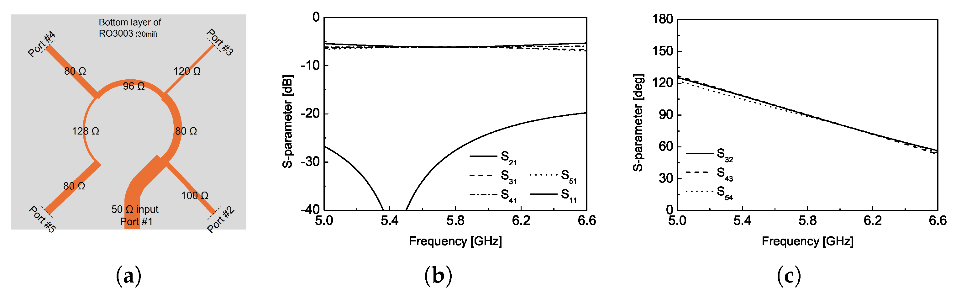
Figure 4 shows a schematic of 1:4 power divider and its S-parameters simulation results. The circularly polarized wave propagation of the proposed antenna design can be achieved by determining a physical rotation,
, and an electrical rotation, which signifies the phase change,
, when
m-number of radiating units are implemented [
14,
15]. In this work, four numbers of the circular-shaped radiating unit given in
Figure 3 will be attached at port 2 ∼ 5 shown in
Figure 4a for the unit CP antenna design. In other words, the integer,
p, and the number of radiating number,
M,
M in the following equation are 2 and 4, respectively.
Figure 4b,c show the magnitude of the S-parameters and the phase differences between ports. For more details, the one-quarter of power division ratio can be obtained at each output port (port 2∼5) and the excellent input impedance-matching characteristic can also be obtained by fine tuning the width of microstrip feed line. The
phase difference between output ports can also be precisely realized by changing the length of microstrip feed lines and its results coincide with the phase requirement for CP propagation calculated from the equation above. In summary, the detailed dimensions of the single radiator and the associated feed line for the 2 × 2 array module are provided in
Table 1.
In the following section, we provide a detailed performance evaluation of the proposed CP array antennas, which are designed based on the single radiator and feed line design presented in this section. First, a single large panel is designed with an 8 × 8 array configuration, consisting of 64 radiating elements. Second, four separate units, each containing a 4 × 4 array, are also fabricated and its radiation characteristics are measured to compare with the single large-panel configuration. This comparison ensures that the proposed antenna structure maintains its performance regardless of the interface between the PA modules and the power-transmitting antenna. Lastly, two large panels, each identical to the initially designed 8 × 8 array antenna, are connected using deployable hinges. Each configuration corresponds to the mounting configurations previously described in
Figure 1.
2.2.2. Array Antenna Characteristics for Various Mounting Scenarios
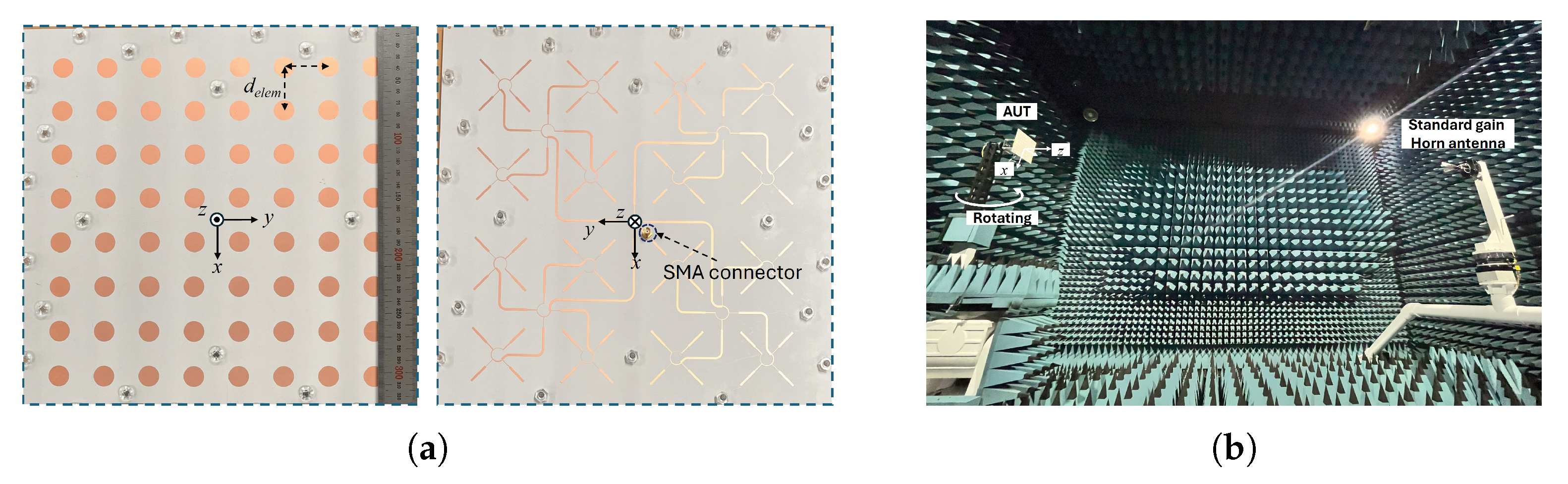
Figure 5 presents photographs of the fabricated CP antenna along with the measurement setup in an anechoic chamber. The circularly shaped radiating patches are arranged with equal spacing, set at a distance of 0.74
, which corresponds to 38.25 mm in terms of the element spacing,
. The specific value of the radiating element spacing is selected considering the size of a commercially available substrate suitable for the mounting configuration. In addition, the chosen spacing helps reduce mutual coupling between elements and improves sidelobe characteristics [
16]. On the rear side of the proposed CP array, the feed network is implemented using microstrip lines. The fundamental structure of the feed line, originally designed to sequentially rotating radiation elements shown in
Figure 4a, is expanded to accommodate all 64 elements in the array. To evaluate the radiation characteristics, the fabricated antenna is tested in an anechoic chamber using a linearly polarized standard gain horn antenna as the reference. The axial ratio and gain characteristics of the proposed antenna are determined while accounting for the polarization mismatch between the antenna under test (AUT) and the horn antenna. A standard gain horn antenna (QRH-002G-018G, MTG, Chungnam, Republic of Korea), operating over the 2–18 GHz frequency range, is employed for the radiation pattern measurements. The anechoic chamber used for the measurement has dimensions of 11 m × 8 m × 8 m, which are sufficient for accurate measurement of the radiation patterns at the center frequency of 5.8 GHz.
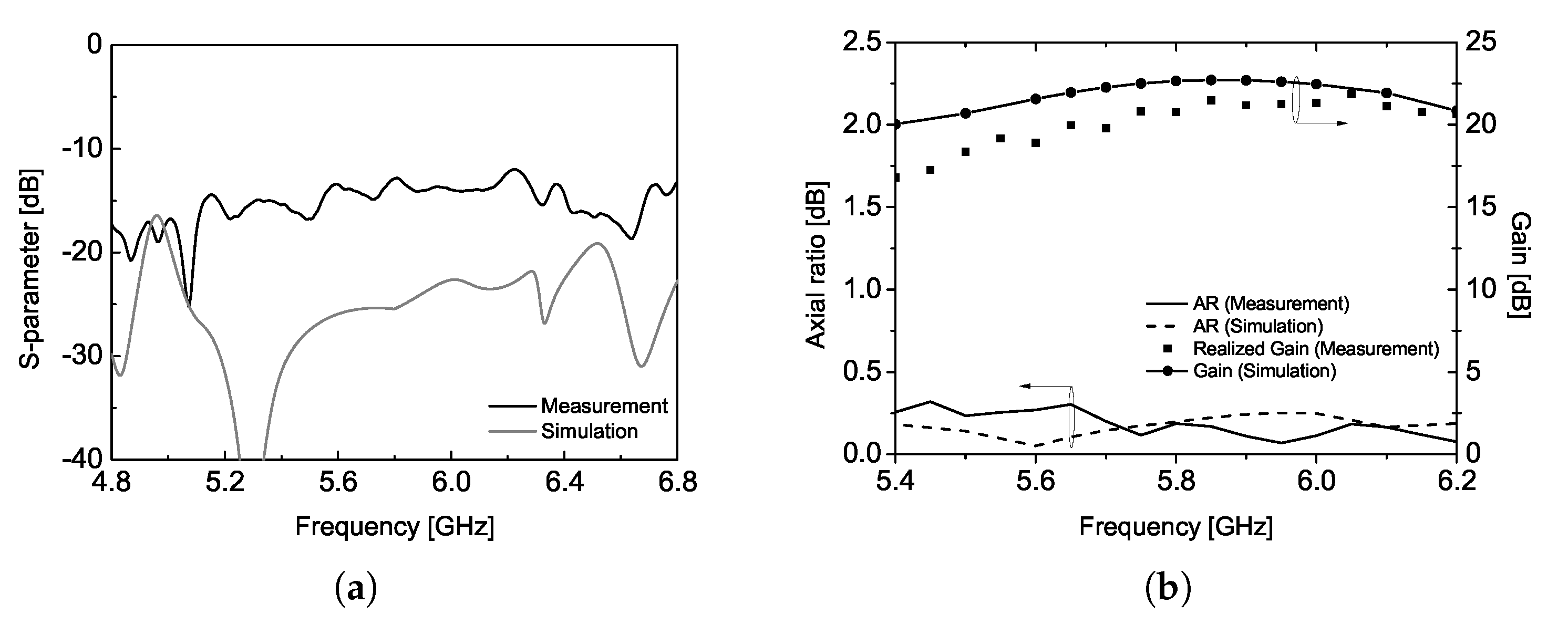
The proposed CP array antenna achieves a gain larger than 20 dBi at the center frequency of 5.8 GHz while demonstrating excellent return loss and axial ratio characteristics over a broad bandwidth. This radiation characteristic is attributed to the unique sequentially rotated feed line, which effectively cancels out reflections near the center frequency at the input port, thereby enhancing the operational bandwidth, as illustrated in
Figure 6. The simulation results agree well with the measured data, validating the proposed antenna design. Note that the return loss was measured using Keysight PNA E8363B.
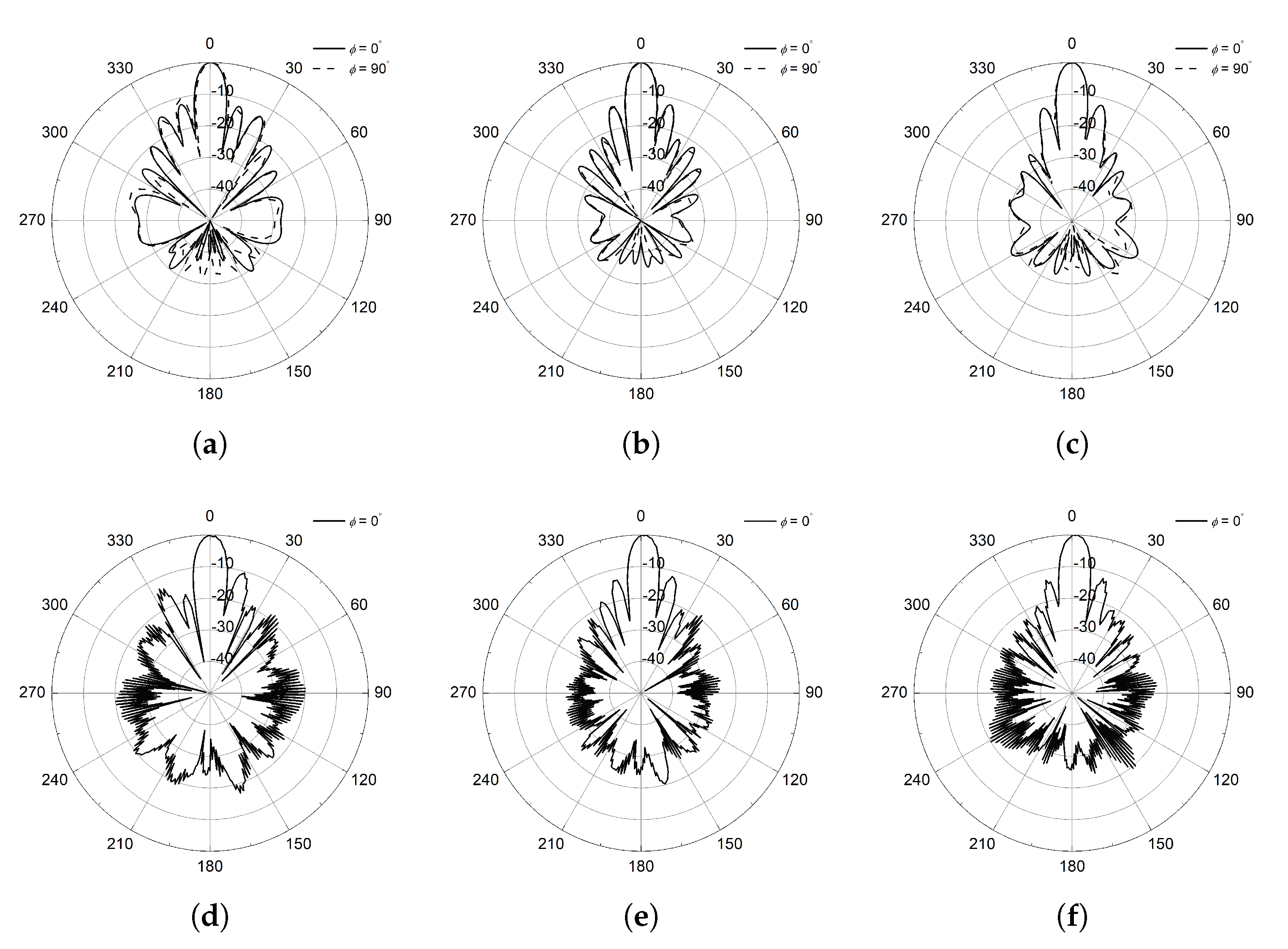
The simulated and measured radiation patterns at various frequency points are shown in
Figure 7. The simulation tool provides the ideal CP radiation patterns and plotted at 5.45, 5.8, and 6.15 GHz. Both ends of the frequency points are selected, for which the sidelobe level is 10 dB smaller than the peak of the pattern and corresponds to about 12% bandwidth. The half-power beamwidth varies between
and
in the operational bandwidth with an extremely small axial ratio less than 0.3 dB. The radiation pattern of the proposed CP antenna is measured using a conventional linearly polarized standard gain horn antenna and the spinning radiation patterns are obtained [
17]. Measurement results shown in
Figure 7d–f provide the agreeable characteristics in terms of the sidelobe level and half-power beamwidth with the simulation results. Please note that the radiation patterns in
are not provided in the measurement results due to the symmetric structure of the proposed CP antenna design. In addition, all radiation patterns presented in this study are normalized to the peak gain values at each frequency to compare the radiation characteristics such as sidelobe level and axial ratio with ease. These experimental results given in
Figure 6 and
Figure 7 can be a reference of the transmitting antenna for WPT application in our study, and it corresponds to the first mounting configuration.
The first mounting configuration of the proposed CP antenna, designed with a large panel, is divided into four units and each unit contains a 4 × 4 CP array antenna with a separate feed point. The fabricated four units of the CP antenna are shown in
Figure 8a, where the units are seamlessly combined to form a large panel which is of identical size with the one from the first configuration. To effectively measure the radiation pattern in the anechoic chamber, an additional 1:4 power divider was designed and fabricated to feed the four input ports using a coaxial cable. This power divider is attached to the rear side of the four units, as depicted in
Figure 8b, with its detailed design provided in
Figure 8c. This configuration corresponds to the second mounting configuration described in
Figure 1, demonstrating that the proposed CP array antenna can be implemented regardless of the interface between the PA modules and the transmitting antenna. In other words, we would like to verify that the proposed CP antenna design, with four separate feed lines, can replace a single large-panel antenna design when WPT system specifications such as efficiency, output power level, or the number of PA modules vary to meet different application requirements. Furthermore, this second mounting configuration is applicable to 27U CubeSats, where multiple separate PA modules interface with the antenna using four coaxial cables, as shown in
Figure 8d as an example.
Figure 8e–i present the measured CP antenna performance, including return loss, gain, axial ratio, and radiation patterns. For more details, the return loss of the fabricated four-unit CP antenna remains below −20 dB at the center frequency of 5.8 GHz, even when measured using a 1:4 power divider along with four pairs of additional SMP connectors and bullets. These SMP connectors and bullets are commercially available from Amphenol (SMP-MSLD series). The radiation characteristics of the fabricated CP antenna, including the gain variation trend with frequency, excellent axial ratio (AR), half-power beamwidth, and sidelobe level, closely resemble those of the CP array antenna designed on a large single panel. These results confirm that the proposed antenna design effectively maintains its radiation performance as a transmitting antenna in the WPT system, regardless of the interface between the PA modules and the transmitting antenna.
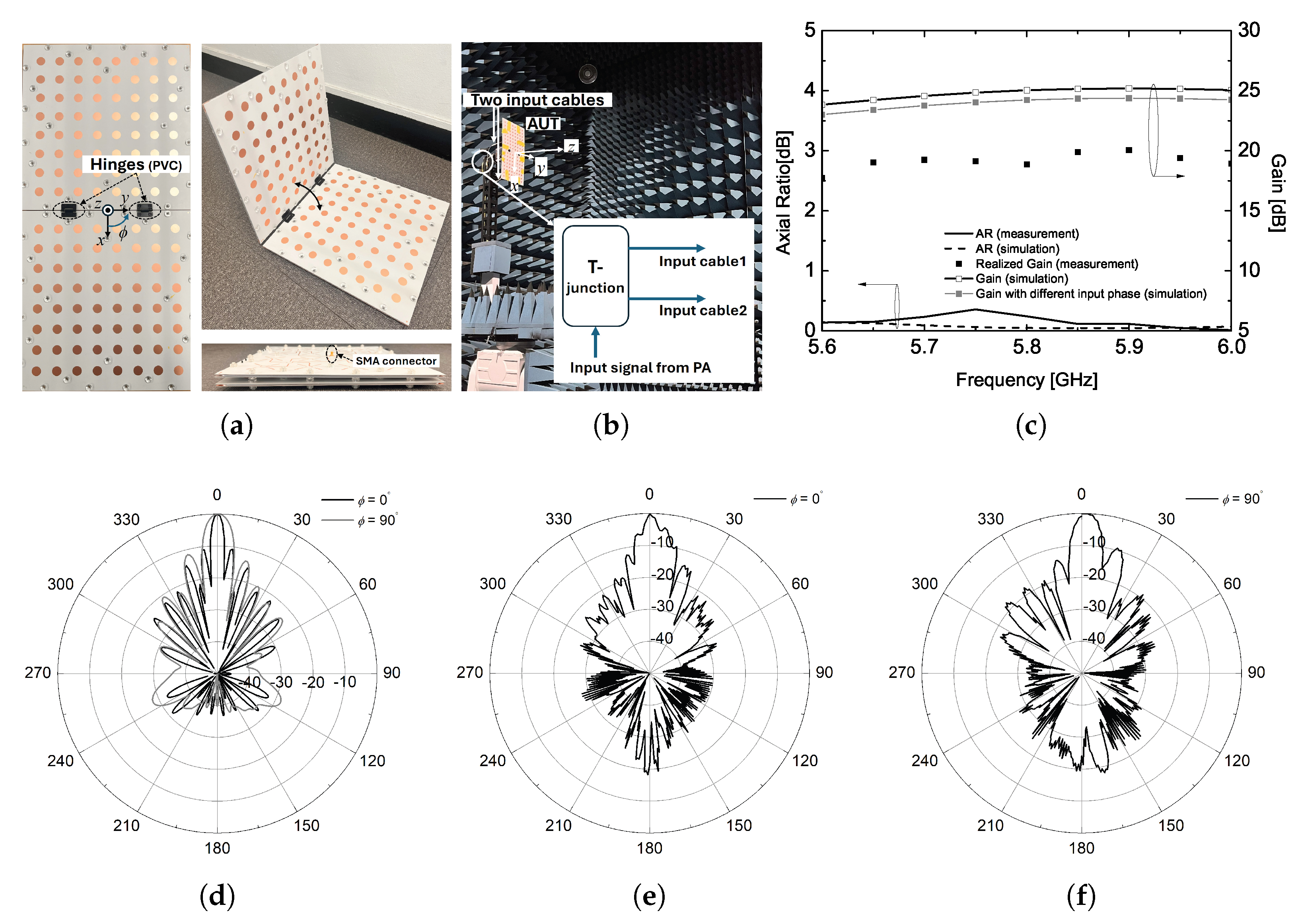
To investigate the radiation characteristics of the transmitting antenna in the third mounting configuration, two large panels are connected using deployable hinges allowing for stowed or deployed configurations. This mechanical operation is feasible because the input SMA connectors for each panel are placed in the same plane when the panels are fully deployed, as illustrated in
Figure 9a. In an anechoic chamber, the input signal from a signal generator is fed into the fabricated antenna through a T-junction and two identical coaxial cables, as depicted in the inset of
Figure 9b. Simulation results indicate that in the
=
plane, the gain increases by 3 dB, and the beamwidth is reduced by half, while the beamwidth in the other plane remains unchanged. It should be noted that the radiation pattern for the third configuration is plotted only at the center frequency of interest, as this frequency is of primary importance for the applicable WPT system.
As shown in the measurement results, the antenna gain with two panels does not reach the values predicted by simulations. From the measured radiation pattern in the
=
plane, it is observed that the first sidelobe unexpectedly shifts too close to the main lobe. This results in a broadened main lobe and the elimination of the first null. To address this issue, further optimization of the radiation patch arrangement along the x-axis is required when connecting the two panels using deployable hinges. Key factors to consider include element spacing, hinge size, and the gap between the two panels. Another important consideration is the input phase response at each feed point. As depicted in the inset of
Figure 9b, each 8 × 8 array antenna is fed using two input coaxial cables during the measurement.
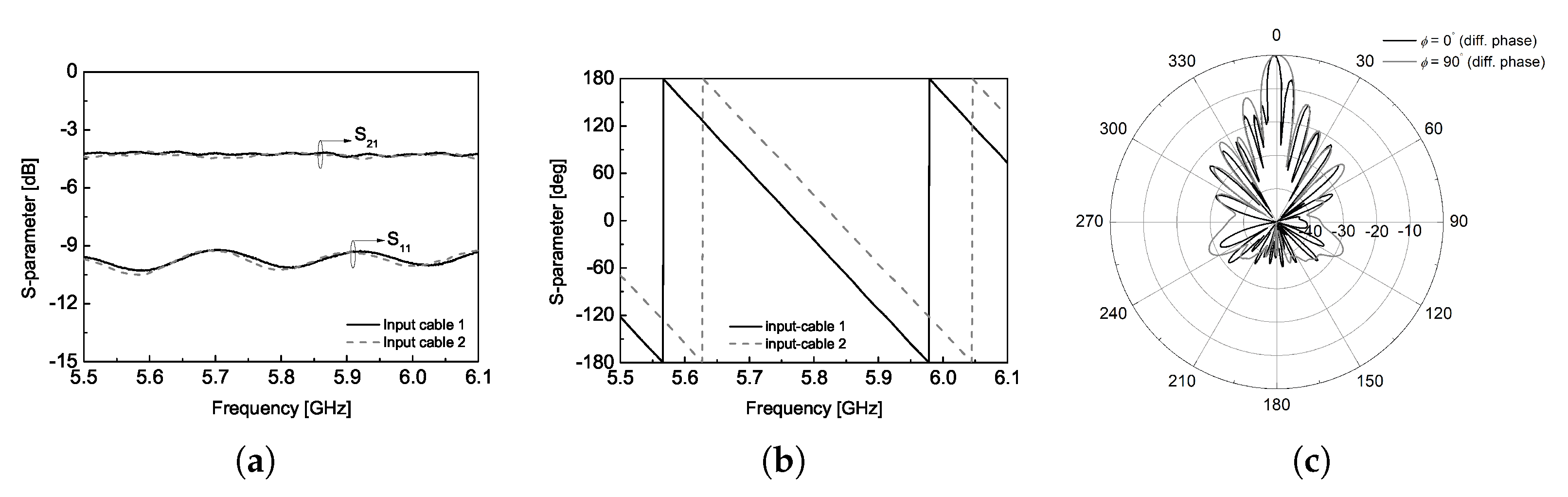
The measured S-parameters of the T-junction with two input cables are provided in
Figure 10. As shown in
Figure 10a, there is minimal magnitude imbalance between the two cables. However, an additional loss of approximately 1 dB is introduced by the cables, and their impedance-matching performance is not optimal. More importantly, a phase imbalance was observed between the two cables, causing a deviation of approximately
between the input signals to the two panels at the center frequency. To evaluate the impact of this phase mismatch, the radiation pattern of the two-panel CP antenna was simulated with different phase excitation.
Figure 10c presents the results when the two input signals have a
phase difference. The simulated radiation pattern shows an obvious tilt in the peak of the
=
plane, along with an increase of approximately 3.25 dB in the first sidelobe level. In addition, this phase imbalance may cause an additional degradation in the antenna gain performance, as shown using the solid gray line in
Figure 9c.


