

Deformation Monitoring Systems for Hydroturbine Head-Cover Fastening Bolts in Hydroelectric Power Plants

 , ,
, ,  , and
, and
Abstract
Highlights
- The synthesis and analysis of available data reveal a significant gap in research on monitoring systems for the deformation of hydroturbine head-cover fastening bolts.
- The analyzed monitoring systems do not guarantee their own operational integrity, including their metrological characteristics.
- The physical integrity of the fastening bolts on hydroturbine head-covers is not guaranteed, increasing the risk of accidents in hydroelectric power plants. Therefore, monitoring systems need to be improved.
- The reliability of the measurement results is not assured, which may thus increase errors in decision making. Metrological self-check should be introduced into monitoring systems.
Abstract
1. Introduction
2. Materials and Methods
3. Operational Stages of a Hydraulic Unit
3.1. Stages of Operation of a Hydraulic Unit
- Zone I—penstock. This zone connects the upstream reservoir, where a volume of water accumulates upstream, thereby generating potential energy. This potential energy is subsequently converted into electrical energy.
- Zone II—spiral chamber, hydroturbine, and generator. In this zone, pressurized water flows through the spiral chamber, where its potential energy is transformed into kinetic energy. As the water enters the engine room, it impinges on the blades of the hydroturbine, converting its kinetic energy into mechanical rotational energy. The hydroturbine axis is coupled to that of the generator, which, upon rotation, converts the rotational energy into medium- or high-voltage alternating current.
- Zone III—downstream reservoir. After relinquishing its energy, the water is discharged downstream of the HPP via a drainage channel.
- Initial preparation—zones I, II, and III are completely drained. The HU is stationary, with neither the rotor nor the electric generator rotating. No electrical load is supplied, as the HU is disconnected from the electrical grid.
- Downstream bypass valve opening—zones I, II, and III are filled to the downstream level. The HU remains stationary, with no rotation of the rotor or electric generator. No electrical load is supplied. Subsequently, the downstream gate is opened.
- Upstream bypass valve opening—zone I is fully flooded to the upstream water level. The HU remains stationary, with no rotation of the rotor or electric generator. No electrical load is supplied. Following this, the upstream gate is opened.
- 4.
- HU unlocking—the hydroturbine blades are unlocked and opened. The HU remains stationary, with no rotation occurring. No electrical load is supplied to the grid.
- 5.
- Opening of downstream gates—the HU begins to rotate and accelerate to its operational speed. Despite reaching operational speed, no power is delivered to the grid.
- 6.
- Stabilization—the rotation frequency of the rotor stabilizes, entering a state commonly referred to as ‘no-load operation’. During this step, the HU continues to operate without transferring power to the grid.
- 7.
- Grid connection—the HU has achieved its operational speed. It is then connected to the electrical grid, enabling the delivery of electrical power.
- 8.
- Grid disconnection—the HU is disconnected from the electrical grid, ceasing power delivery.
- 9.
- Closing of upstream gates—the water level begins to decrease. As a result, the HU gradually slows down until it stops.
- 10.
- The water level in zones I, II, and III decreases to the downstream level, ensuring the HU is stationary.
- 11.
- Zones I, II, and III are then fully drained, completing the shutdown process. The downstream gate is closed.
3.2. Behavior of the Head During Operational Stages of the Hydraulic Unit
4. Vibrations and Deformations in Francis Turbines
4.1. Vibrations in Hydroturbines: Causes, Consequences, and Mitigation Methods
4.1.1. Causes and Consequences of Vibrations
4.1.2. Methods for Mitigating Vibration
- Improving vibration governance systems [32].
4.2. Mechanical Stresses and Deformations in a Hydroturbine
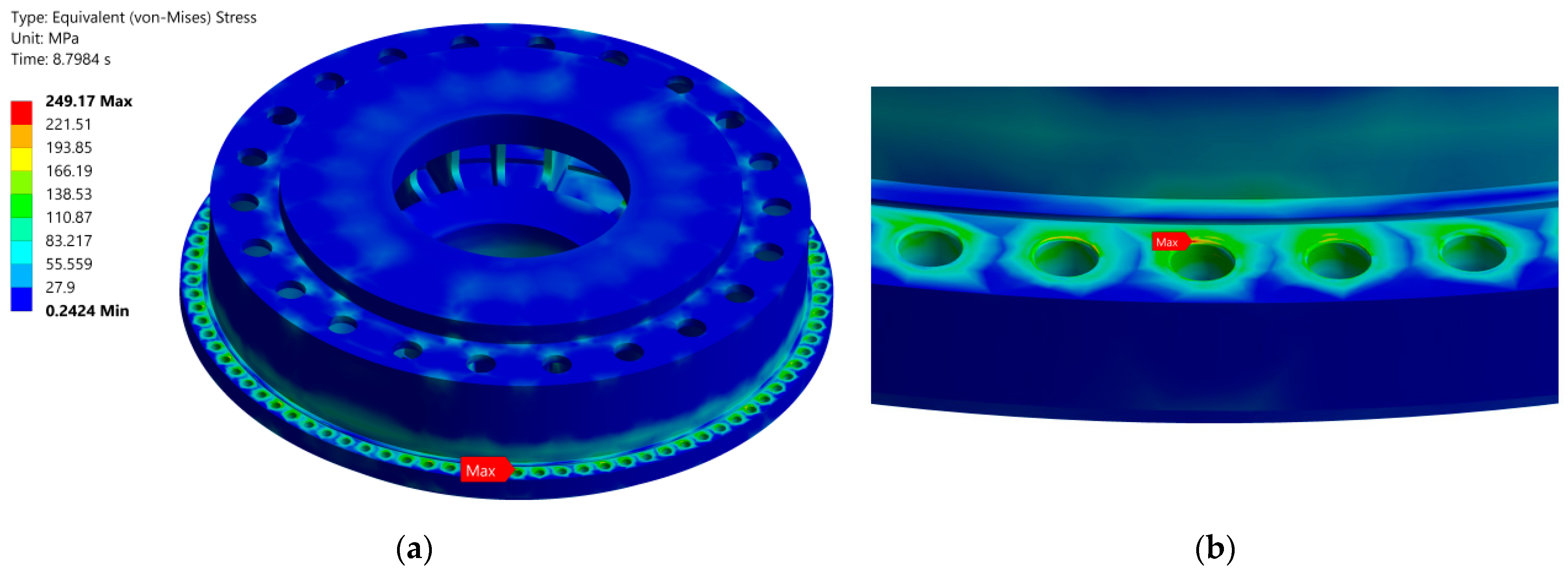
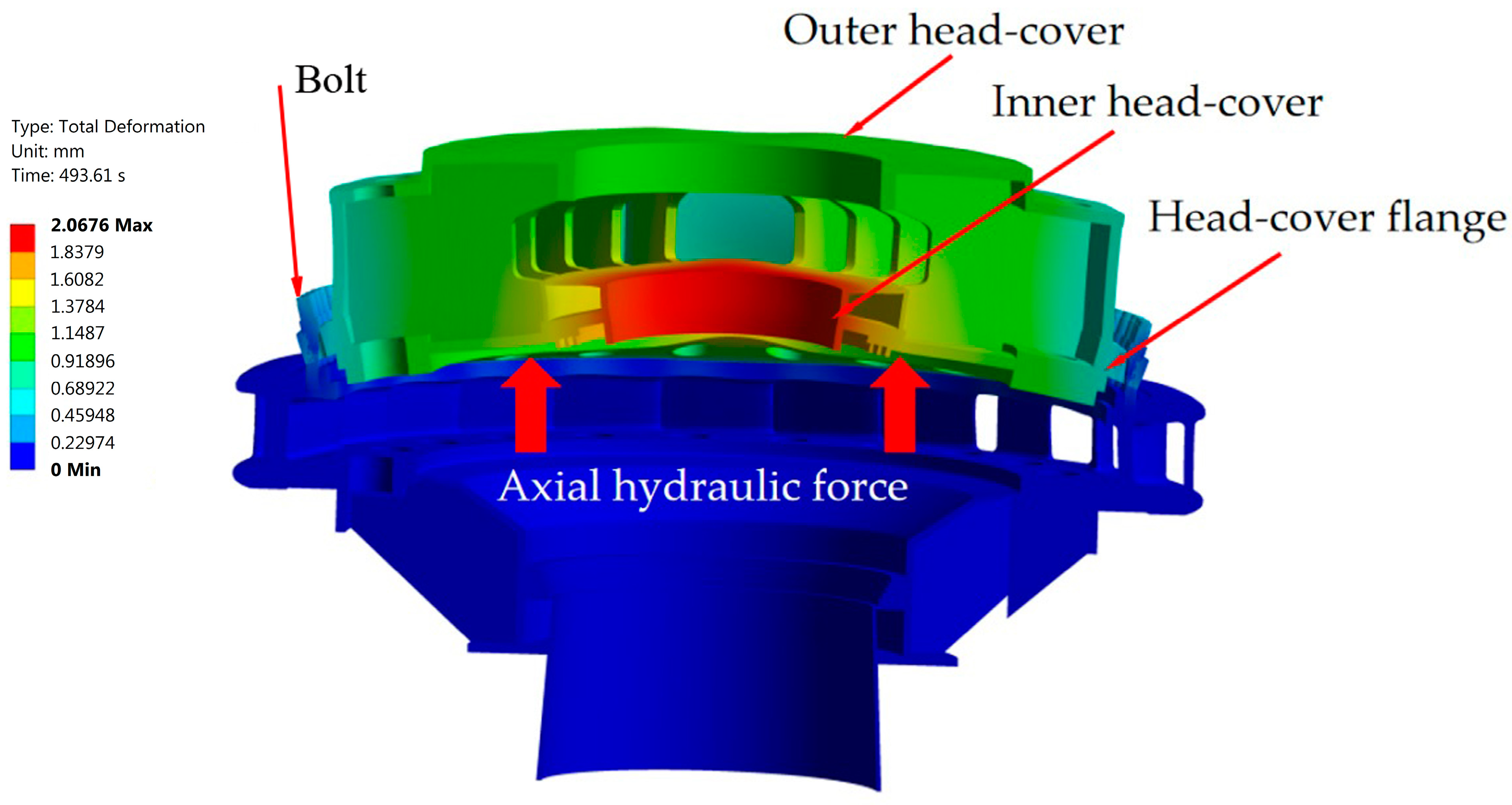
4.2.1. Mechanical Stresses and Deformations in the Hydroturbine Head-Cover
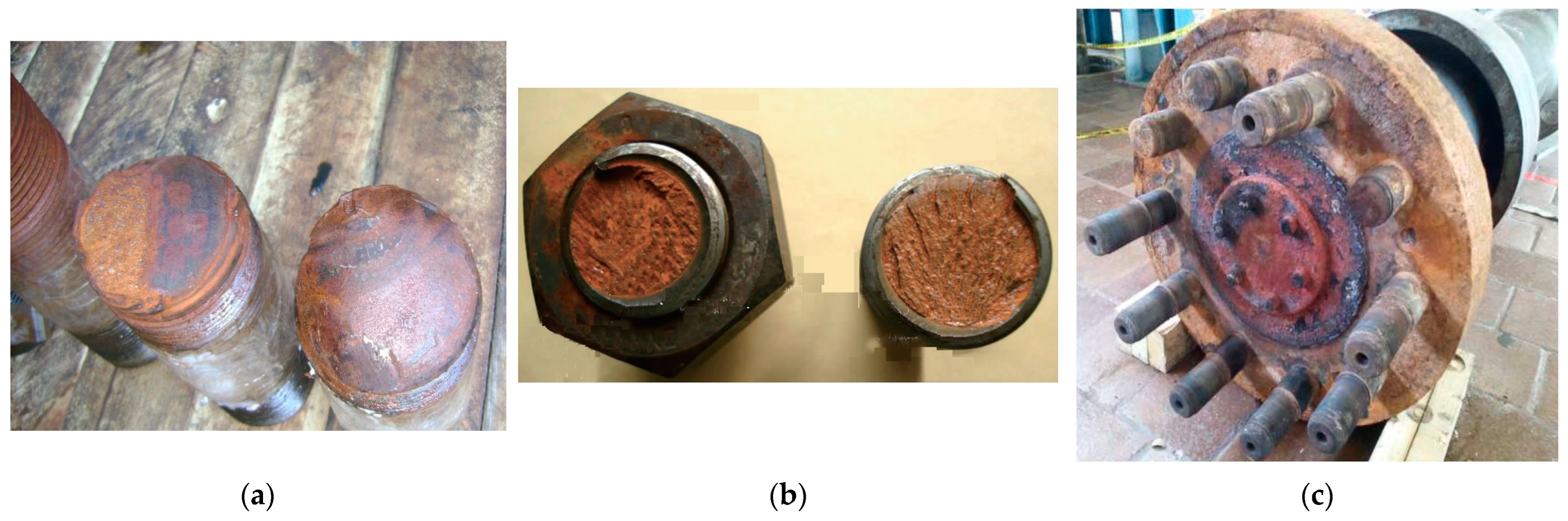
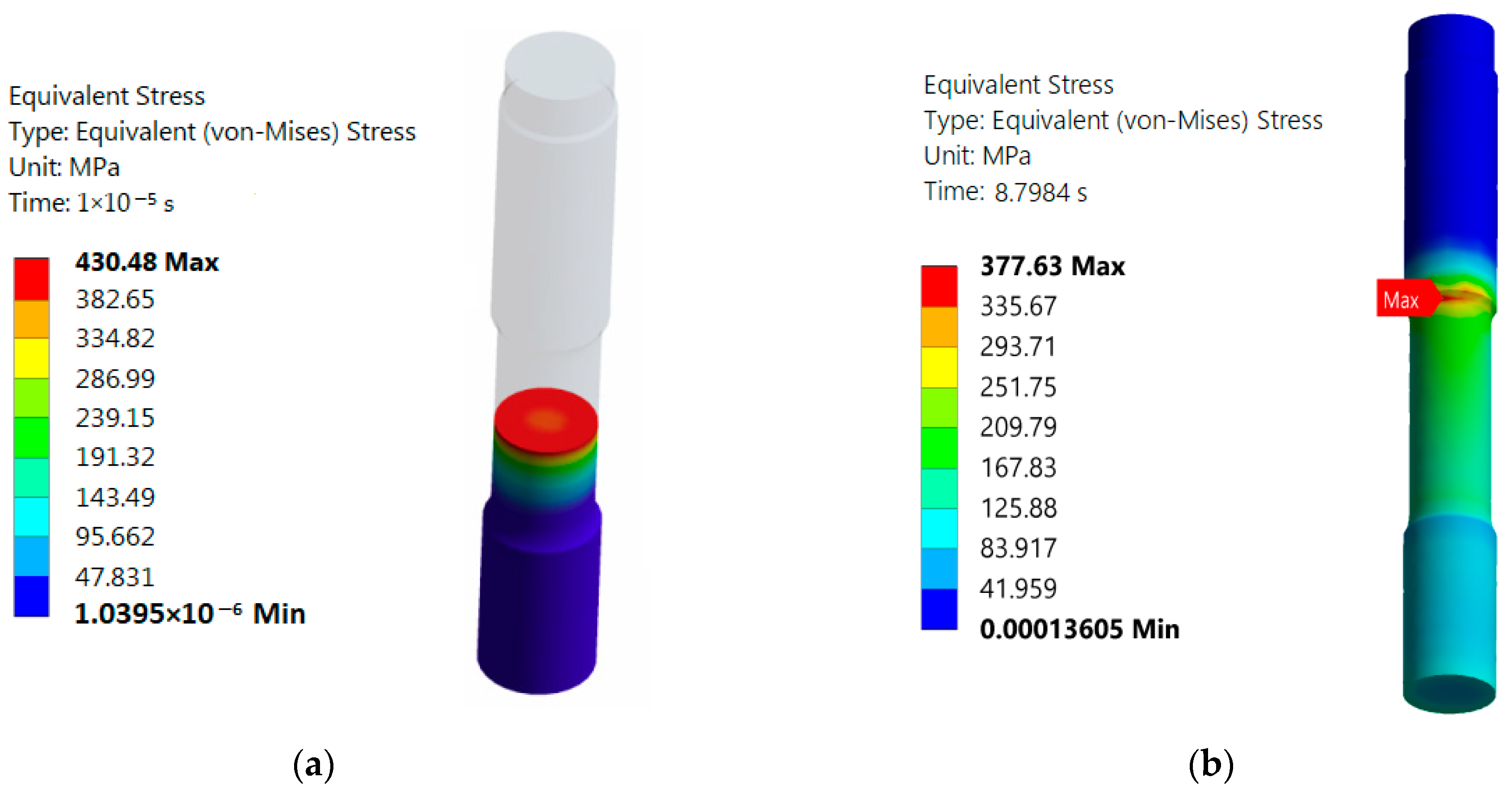
4.2.2. Mechanical Stresses and Deformations in the Fastening Bolts of Hydroturbine Head-Covers
- Elastic deformations are present throughout different operational phases, specifically during start-up, steady-state operation under partial and full loads, load transients, and shutdown. Elastic deformations arise from the gradual increase in water pressure and hydrodynamic forces. The hydroturbine head-cover is subjected to constant loads, including water pressure, centrifugal forces, and its own weight, which induce reversible elastic deformations. Consequently, similar elastic deformations also occur in the fastening bolts.
- Plastic deformations are associated with transient events such as water hammer, electrical failures, and load rejection. During these events, extreme pressure peaks, particularly those occurring in water hammer incidents, can surpass the elastic limit of the material, resulting in permanent deformations.
- Fatigue deformations appear under intense cyclic loading, which can accelerate the appearance of fatigue in the fastening bolts.
- Torsional deformations may arise during the tightening process or under operational conditions where bolts are subjected to torsional loads. Specifically, during tightening, bolts experience torsional stress as a result of the applied torque. This stress is not typically a deformation issue but rather a factor in achieving the desired preload.
- Shear deformations can occur under specific conditions like fault slip or asymmetric hydraulic forces, particularly during transient events.
- Creep deformation is more likely to occur after extended periods of continuous operation, although its likelihood also depends on the material properties of the structures. Elevated component temperatures, resulting from friction or heat transfer from the water, can also accelerate creep deformation over time.
5. Instruments for Vibration Measurement and Methods for Measuring Deformations in Francis Turbines
5.1. Instruments for Vibration Measurement
5.2. Methods for Enhancing the Effectiveness of Vibration Monitoring Systems
- Consider the ISO 20816-5:2018 standard, which outlines methodologies for measuring various vibration parameters (displacement, velocity, and acceleration) and specifies the points and directions for measurements [57];
- Use the requirements of GOST R 70810-2023, which establishes guidelines for measuring vibration at support nodes (bearings) and criteria for interpreting measurement results, aiding in decision making regarding the need for equipment repair or maintenance [55];
5.3. Methods for Measuring Mechanical Stress and Deformation
6. Monitoring Systems for Hydroturbine Head-Cover Fastening Bolts at SSHPPs
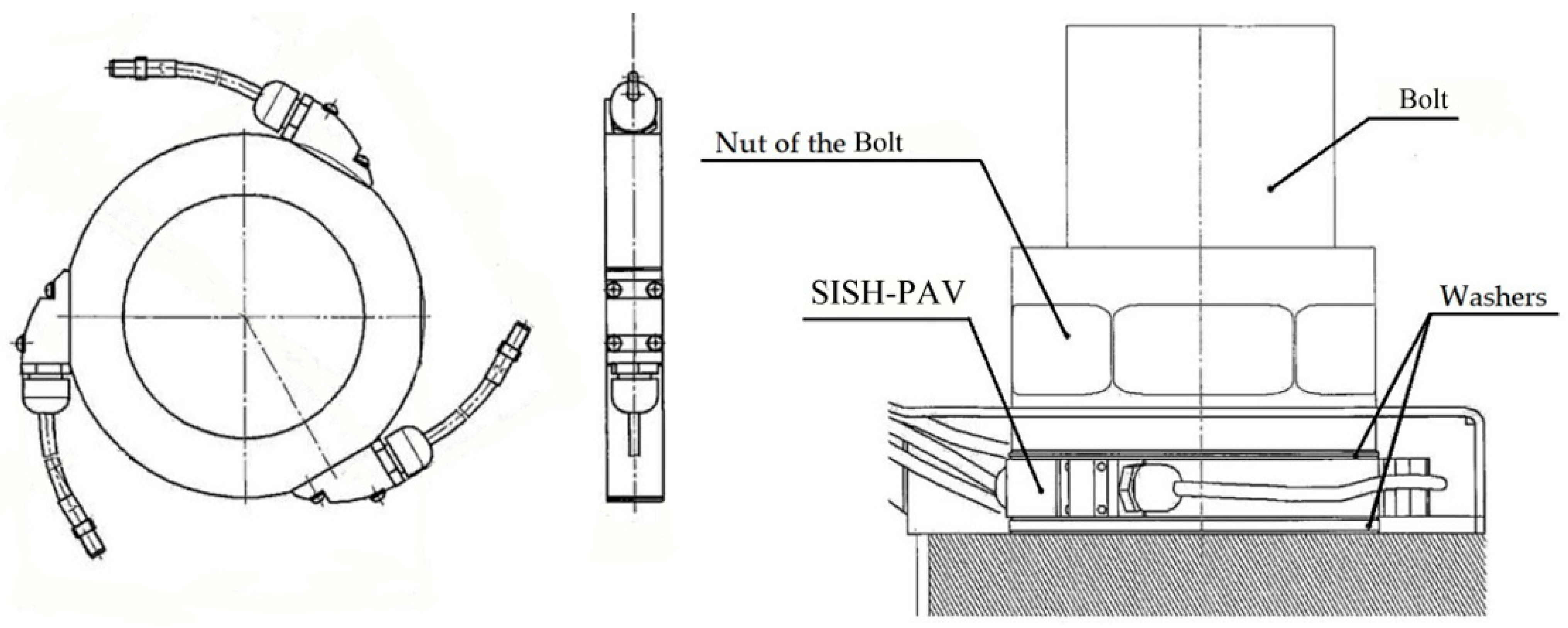
6.1. Mechanical Stress Monitoring System
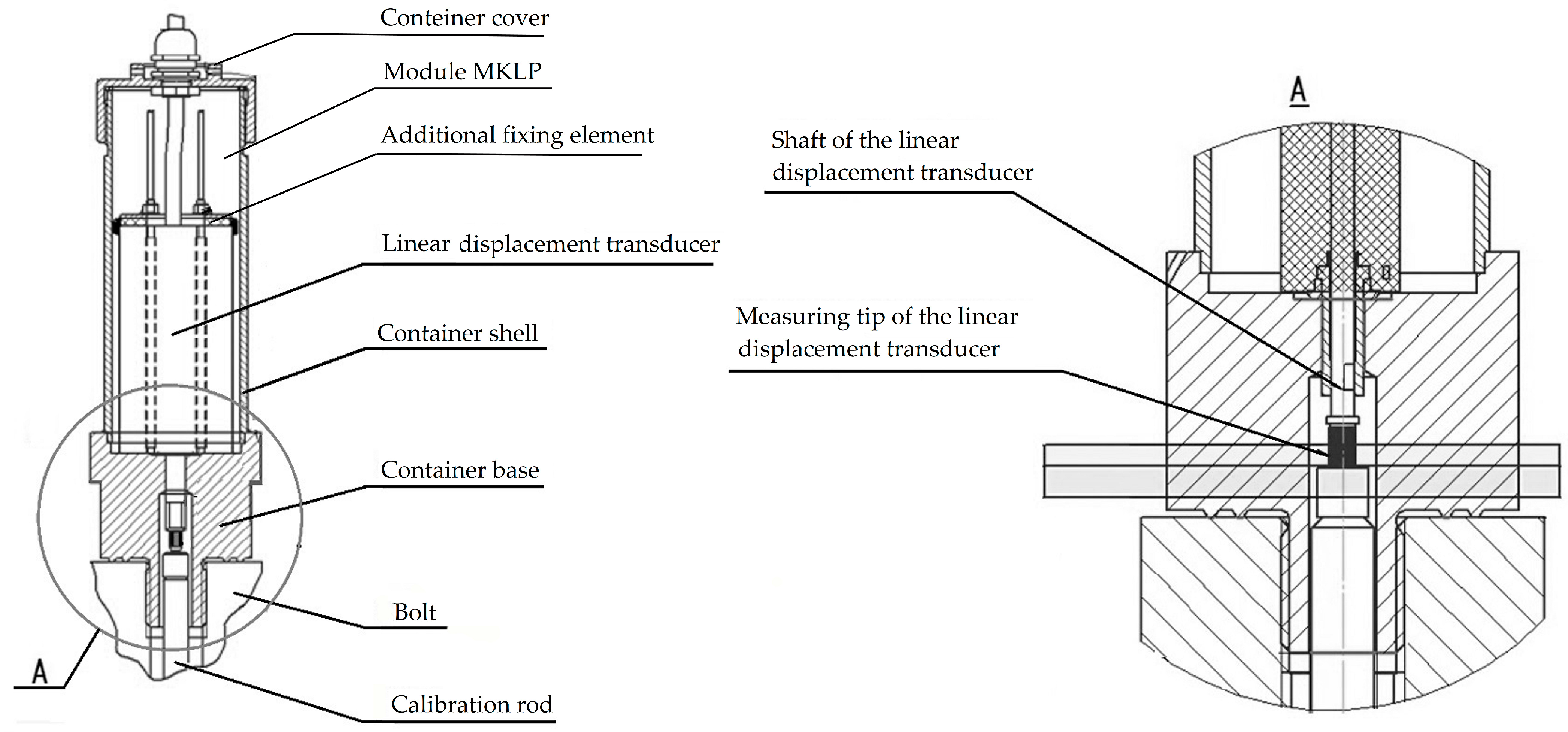
6.2. Deformation Monitoring Systems
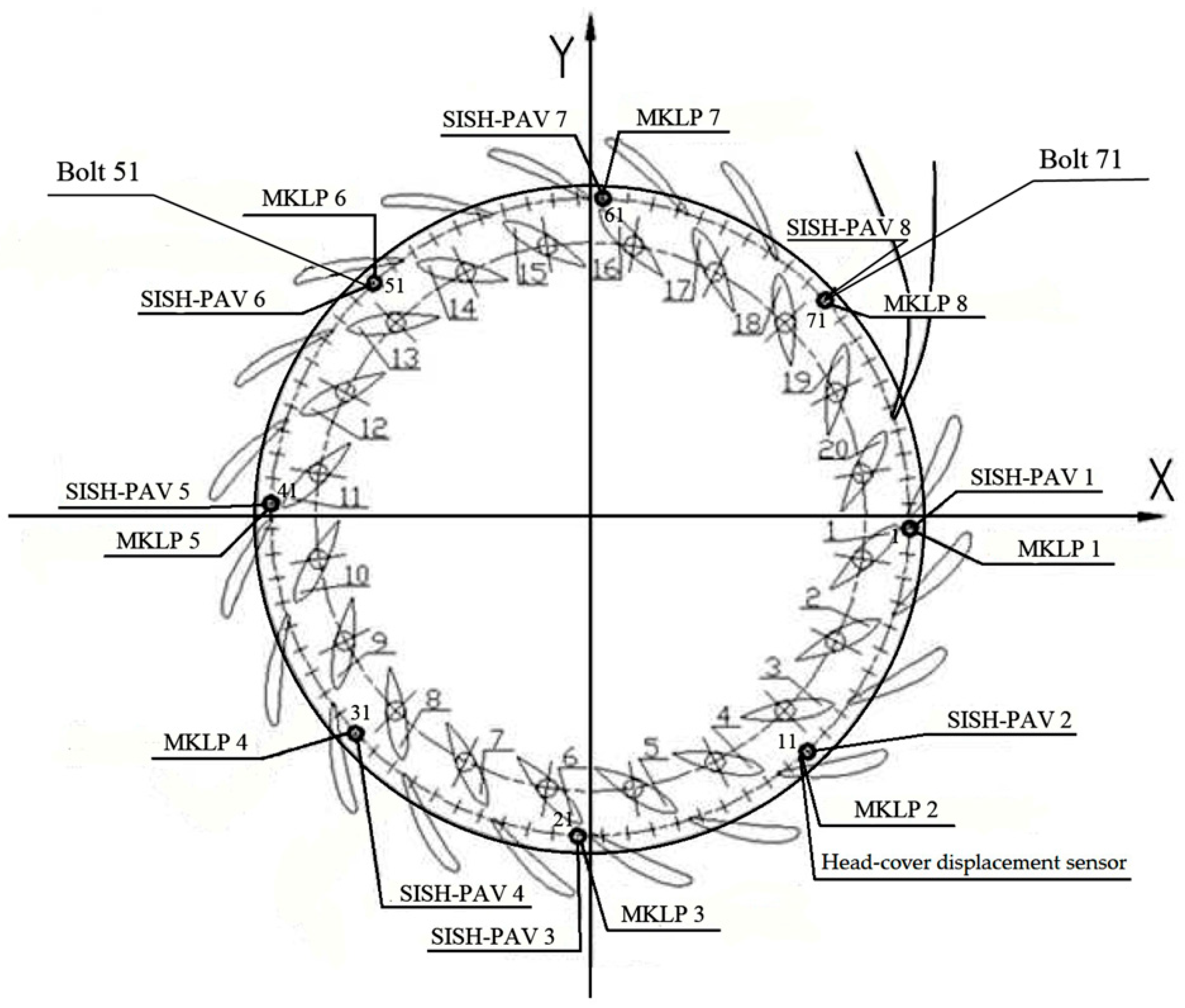
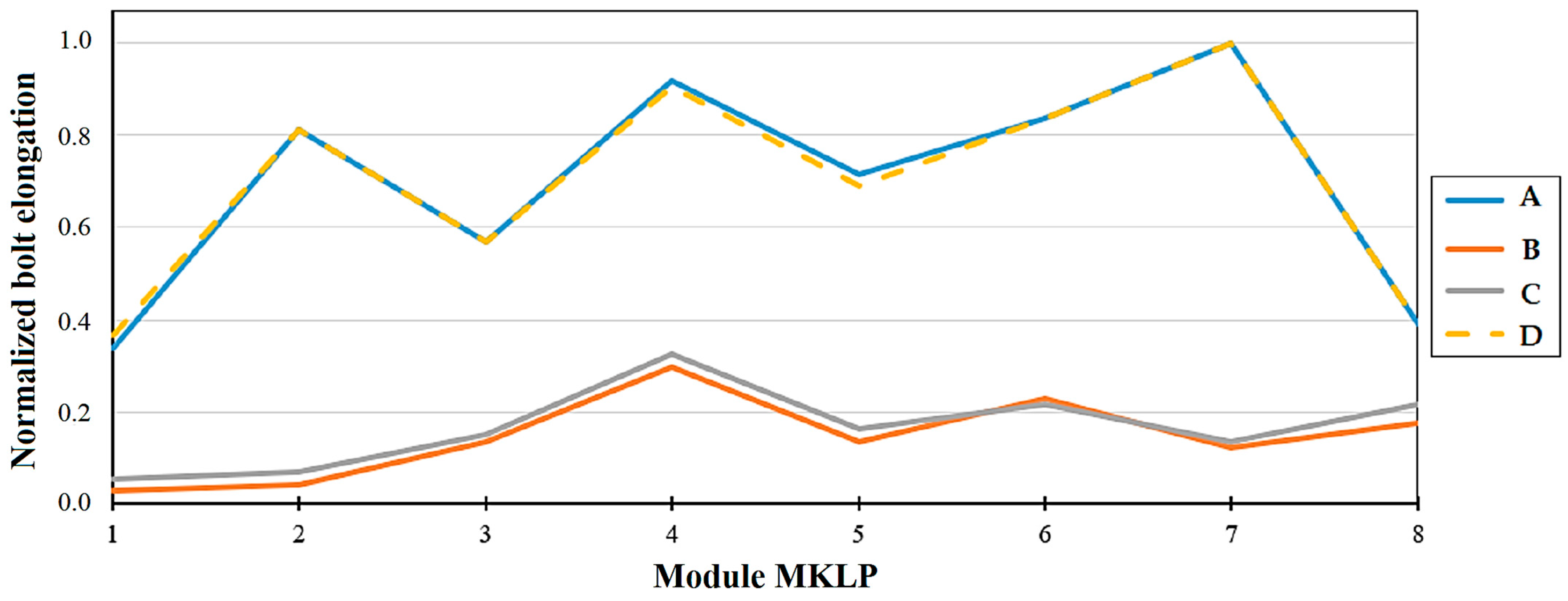
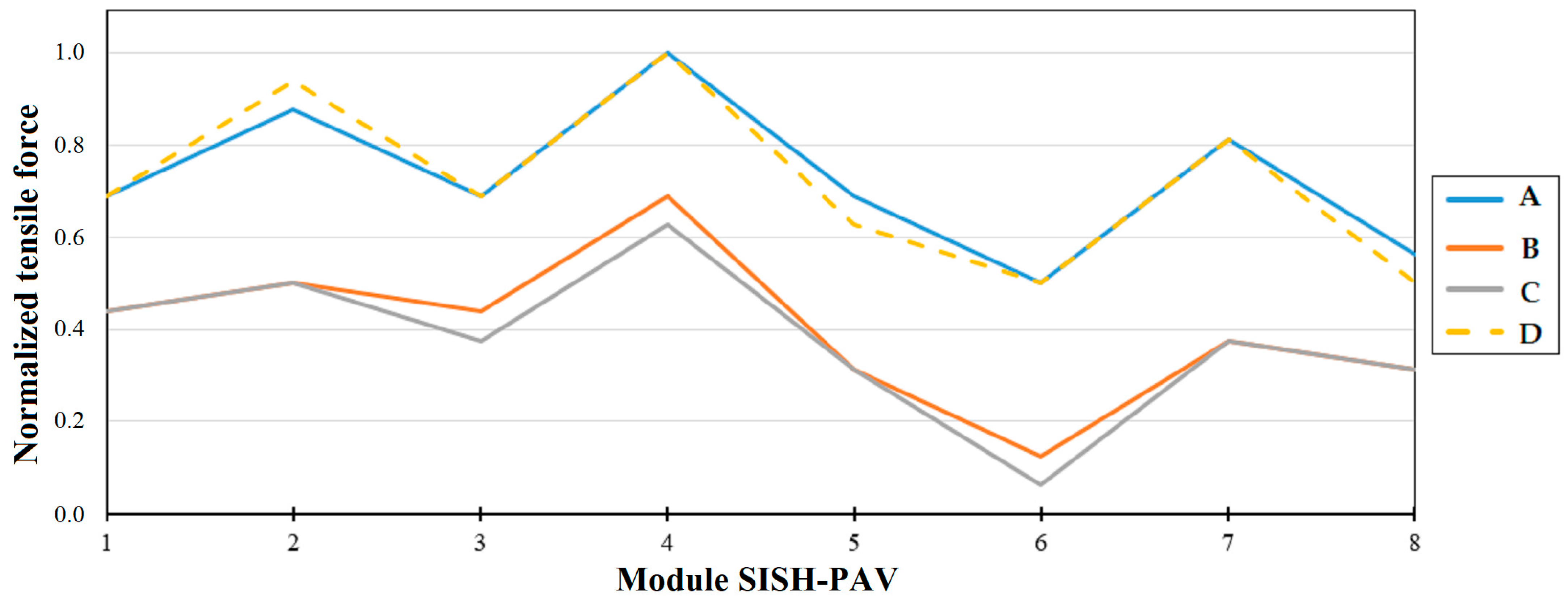
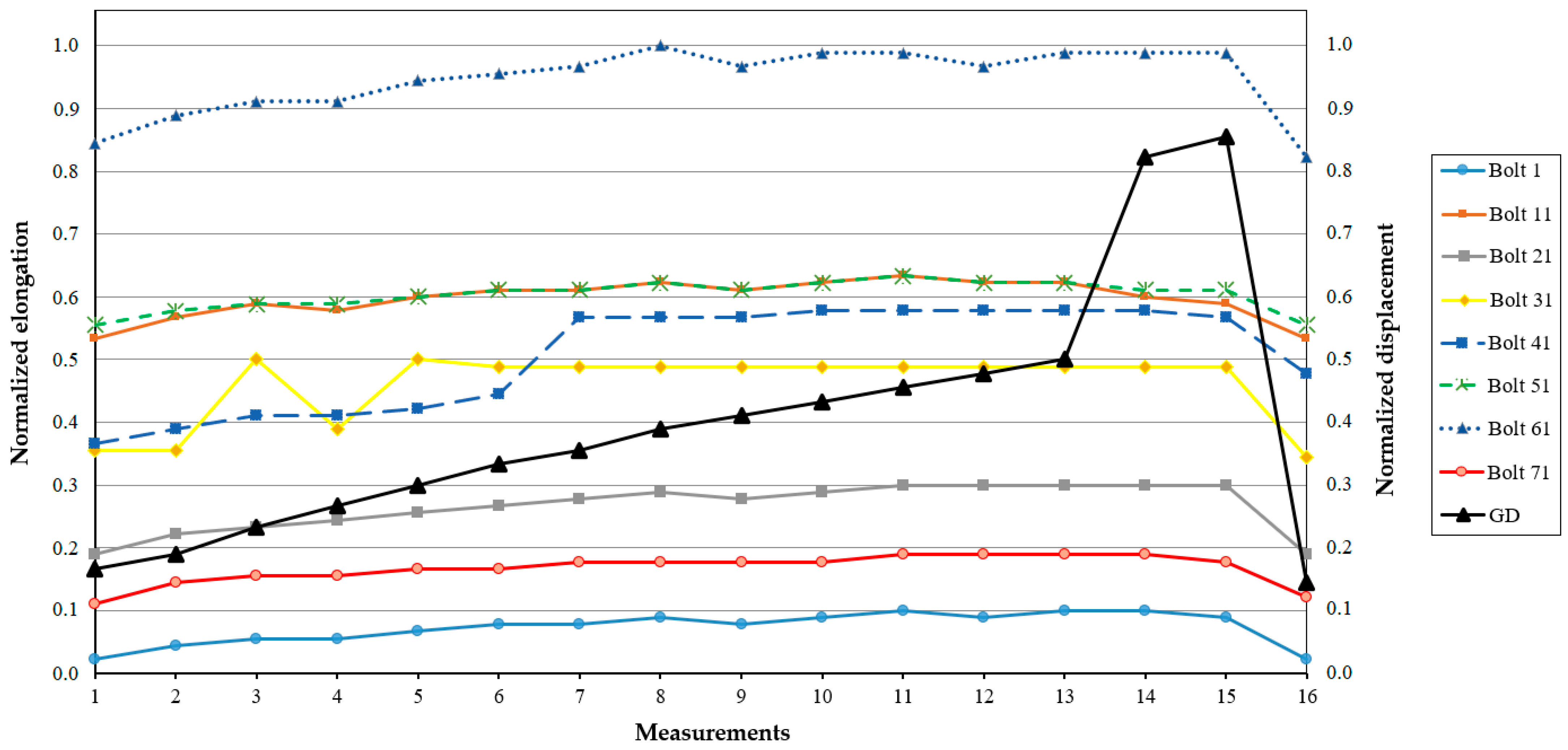
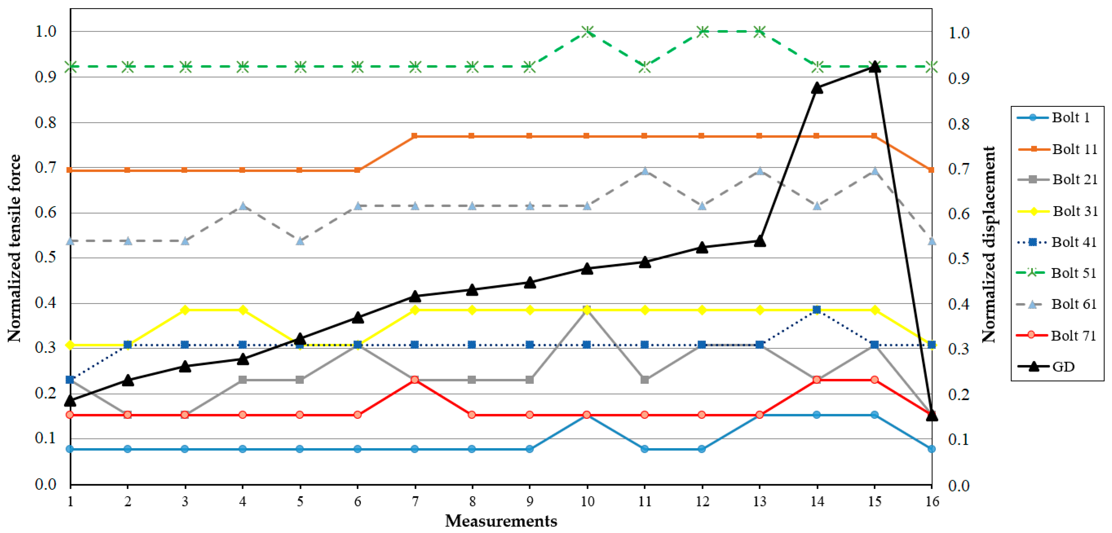
6.3. Deformations and Tensile Forces in the Hydroturbine Head-Cover Fastening Bolts
- Head (the vertical difference in water levels between the upper and lower reservoirs).
- Displacement of the hydroturbine guide vanes using a guide device (GD), which regulates water flow to the runner for controlling turbine power.
- Water pressure in the spiral chamber.
- Vertical displacement of the hydroturbine head-cover.
- Elongation of the fastening bolts.
- Force exerted by the bolt on the hydroturbine head-cover.
- Before the flow section is drained.
- After its filling.
- During rotor unlocking.
- During the operation of the hydraulic unit in the electrical grid.
7. Analysis and Discussion
- Self-check function—the implementation of a self-check function in measurement sensors enables the autonomous evaluation of their functionality and performance, eliminating the need for external intervention. Advanced sensors can perform metrological self-checks by comparing their measurements against built-in reference standards, thereby ensuring long-term accuracy and reliability [94]. In networked systems, self-checking sensors can transmit status alerts, facilitating proactive maintenance and preventing data corruption caused by malfunctioning sensors [95].
- Artificial Intelligence (AI) for sensor assurance—AI tools, such as neural networks and machine learning algorithms, generate reference models that capture ‘normal’ sensor behavior. These models enable the detection of deviations resulting from tampering or natural degradation [96]. Additionally, by distinguishing between normal drift patterns and abnormal deviations, AI facilitates sensor self-calibration, thereby reducing the necessity for manual recalibration and ensuring consistent measurement accuracy over time [97].
- Digital Twins—developing a virtual physical replica of the measurement sensor or simulating the process of fastening bolt deformation could accurately reflect and predict the behavior of their physical counterparts in real time. This approach enables the simulation of the measurement system’s behavior to estimate measurement uncertainty, allowing immediate adjustments and optimizations that ensure high-quality measurements and reduce the risk of accidents [98].
- The impact of vibrations on contact and non-contact measuring sensors due to the presence of axial and horizontal vibrations during the operational stages of the hydraulic unit;
- The deformations of the fastening bolts in the operating stages of the hydraulic unit due to fatigue deformation can occur before the maximum plastic deformation leads to the failure of the bolt.
8. Conclusions
- This research supports, based on the results of practical tests published in SSHPPs, the theoretical models that describe the non-uniform behavior of deformations in the fastening bolts of the hydroturbine head-cover.
- The analysis of the information has shown that static and cyclic loads can lead to a gradual degradation of bolts over time, as well as induce fatigue, leading to bolt weakening. Therefore, the development of new deformation monitoring systems for fastening bolts must consider the cumulative damage resulting from both static and dynamic effects.
- As the analyzed deformation monitoring systems for fastening bolts, KM-Delta-8-CM and PTK KM-Delta, do not fully guarantee the reliability of the measurement sensors, it is necessary to develop improvements based on new approaches and technologies such as AI for ensuring the safety and increasing the operational uptime of the hydraulic unit.
- In developing a deformation monitoring system for the fastening bolts of a hydroturbine head-cover, it is essential to consider the effects of vibrations on the measuring sensors, as well as the bolt deformations that occur during various operational stages of the hydraulic unit.
Author Contributions
Funding
Data Availability Statement
Conflicts of Interest
Abbreviations
| HPP | Hydroelectric Power Plant |
| IHA | International Hydropower Association |
| IEA | International Energy Agency |
| SSHPP | Sayano-Shushenskaya Hydroelectric Power Plant |
| HU | Hydraulic Unit |
| CFD | Computational Fluid Dynamics |
| FEA | Finite Element Analysis |
| SAW | Surface-Active Wave |
| SSI | Silent Speech Interface |
| RTU | Remote Terminal Unit |
| SISH-PAV | Surface Acoustic Wave Force-measuring Washer |
| MKLP | Measuring Linear Displacement |
| GD | Guide Device |
| AI | Artificial Intelligence |
References
- International Hydropower Association. 2024 World Hydropower Outlook. Available online: https://www.hydropower.org/ (accessed on 9 May 2024).
- Nguyen, M.P.; Ponomarenko, T.; Nguyen, N. Energy Transition in Vietnam: A Strategic Analysis and Forecast. Sustainability 2024, 16, 1969. [Google Scholar] [CrossRef]
- Bogoviz, A.V.; Lobova, S.V.; Alekseev, A.N. Current State and Future Prospects of Hydro Energy in Russia. Int. J. Energy Econ. Policy 2020, 10, 482–488. [Google Scholar] [CrossRef]
- Lieskoski, S.; Koskinen, O.; Tuuf, J.; Björklund-Sänkiaho, M. A Review of the Current Status of Energy Storage in Finland and Future Development Prospects. J. Energy Storage 2024, 93, 112327. [Google Scholar] [CrossRef]
- Molla, S.; Farrok, O.; Alam, M.J. Electrical Energy and the Environment: Prospects and Upcoming Challenges of the World’s Top Leading Countries. Renew. Sustain. Energy Rev. 2024, 191, 114177. [Google Scholar] [CrossRef]
- Matrenin, P.V.; Stepanova, A.I. Enhancing the Interpretability of Electricity Consumption Forecasting Models for Mining Enterprises Using Shapley Additive Explanations. J. Min. Inst. 2024, 271, 154–167, EDN DEFRIP. [Google Scholar]
- Abramovich, B.N.; Bogdanov, I.A. Improving the Efficiency of Autonomous Electrical Complexes of Oil and Gas Enterprises. J. Min. Inst. 2021, 249, 408–416. [Google Scholar] [CrossRef]
- Semenova, T.; Martínez Santoyo, J.Y. Increasing the Sustainability of the Strategic Development of Oil Producing Companies in Mexico. Resources 2024, 13, 108. [Google Scholar] [CrossRef]
- International Energy Agency. Net Zero by 2050—A Roadmap for the Global Energy Sector. Available online: https://www.iea.org/reports/net-zero-by-2050 (accessed on 10 October 2024).
- Gezer, D.; Taşcıoğlu, Y.; Çelebioğlu, K. Frequency Containment Control of Hydropower Plants Using Different Adaptive Methods3. Energies 2021, 14, 2082. [Google Scholar] [CrossRef]
- Alonso, A.; Robert, G.; Besançon, G.; Hildebrand, R. Hydropower Plants Modelling for Monitoring Purposes. IFAC-PapersOnLine 2023, 56, 2281–2286. [Google Scholar] [CrossRef]
- Kyтьин, Н.Г. и дp. Aкт Тeхничecкoгo Paccлeдoвaния Пpичин Aвapии нa Caянo-Шyшeнcкoй ГЭC. Available online: https://www.plotina.net/pdf/sshges_rtn.pdf (accessed on 11 May 2024).
- Wang, Z.; Yang, J.; Wang, W.; Qu, J.; Huang, X.; Zhao, W. Research on the Flow-Induced Stress Characteristics of Head-Cover Bolts of a Pump-Turbine during Turbine Start-Up. Energies 2022, 15, 1832. [Google Scholar] [CrossRef]
- Casanova, F.; Mantilla, C. Fatigue Failure of the Bolts Connecting a Francis Turbine with the Shaft. Eng. Fail. Anal. 2018, 90, 1–13. [Google Scholar] [CrossRef]
- Плoтинa.Нeт Aвapия нa Caянo-Шyшeнcкoй ГЭC: Peaльнocть и Мифы. Available online: https://www.plotina.net/sshges-rassokhin-3 (accessed on 12 May 2024).
- Vagnoni, E.; Valentin, D.; Avellan, F. Dynamic Behaviour of a Francis Turbine during Voltage Regulation in the Electrical Power System. Int. J. Electr. Power Energy Syst. 2021, 125, 106474. [Google Scholar] [CrossRef]
- Goulliver Jonh, S.; Arndt Roger, E. Hydropower Engineering Handbook; Goulliver Jonh, S., Ed.; McGRAW-HILL: Minneapolis, MN, USA, 1991; Volume 1. [Google Scholar]
- Wang, L.; Wang, Z.; Yang, S.; Yu, S.; Wei, Z. Study on the Dynamic Response Behaviour of the Head Cover-Bolts-Stay Ring of a Variable-Speed Pump-Turbine. J. Phys. Conf. Ser. 2024, 2854, 012091. [Google Scholar] [CrossRef]
- Jia, Y.; Li, F.C.; Wei, X.Z.; Li, X.B.; Li, Z.H. A Method for Analysis of Head Cover Deformation and Vibration Amplitude in Francis Hydro-Turbine System by Combination of CFD and FEA. J. Mech. Sci. Technol. 2017, 31, 4255–4266. [Google Scholar] [CrossRef]
- Egusquiza, M.; Presas, A.; Valentin, D.; Valero, C.; Xu, B.; Chen, D.; Egusquiza, E. Diagnostics of a Hydraulic Turbine Failure. In Proceedings of the 18th IMEKO TC10 Conference “Measurement for Diagnostics, Optimisation and Control to Support Sustainability and Resilience”, Warsaw, Poland, 26–27 September 2022; pp. 119–122. [Google Scholar]
- Ilyushin, Y.V.; Asadulagi, M.-A.M. Development of a Distributed Control System for the Hydrodynamic Processes of Aquifers, Taking into Account Stochastic Disturbing Factors. Water 2023, 15, 770. [Google Scholar] [CrossRef]
- Mohanta, R.K.; Chelliah, T.R.; Allamsetty, S.; Akula, A.; Ghosh, R. Sources of Vibration and Their Treatment in Hydro Power Stations—A Review. Eng. Sci. Technol. Int. J. 2017, 20, 637–648. [Google Scholar] [CrossRef]
- Тapacoв, B.Н. Bибpaция и Динaмичecкaя Уcтoйчивocть Гидpoaгpeгaтa. Available online: https://www.diamech.ru/files/dinamicheskaya_ustoichivost_gidroagregatov.pdf (accessed on 18 June 2024).
- Kurzin, V.B.; Seleznev, V.S. Mechanism of emergence of intense vibrations of turbines on the Sayano-Shushensk Hydro Power Plant. J. Appl. Mech. Tech. Phys. 2010, 51, 166–175, EDN LNXQNR. [Google Scholar] [CrossRef]
- Abdulmyanov, T.; Epifanova, L.; Epifanov, V.; Mardanova, A. Simulation of Resonant Vibrations in Hydraulic Units of HPP with a Wide Range of Working Area. Becтник Kaзaнcкoгo Гocyдapcтвeннoгo Энepгeтичecкoгo Унивepcитeтa 2022, 14, 113–123, EDN IMZUDR. [Google Scholar]
- Shi, Y.; Zhou, J.; Lai, X.; Xu, Y.; Guo, W.; Liu, B. Stability and Sensitivity Analysis of the Bending-Torsional Coupled Vibration with the Arcuate Whirl of Hydro-Turbine Generator Unit. Mech. Syst. Signal Process 2021, 149, 107306. [Google Scholar] [CrossRef]
- Haţiegan, C.; Pădureanu, I.; Jurcu, M.; Nedeloni, M.D.; Hamat, C.O.; Chioncel, C.P.; Trocaru, S.; Vasile, O.; Bădescu, O.; Micliuc, D.; et al. Vibration Analysis of a Hydro Generator for Different Operating Regimes. IOP Conf. Ser. Mater. Sci. Eng. 2017, 163, 012030. [Google Scholar] [CrossRef]
- Wu, Y.; Li, S.; Liu, S.; Du, H.-S.; Qian, Z. Vibration of Hydraulic Machinery; Marco, C., Ed.; Springer: London, UK, 2013; Volume 11, pp. 442–448. [Google Scholar]
- Melnikova, O.; Nazarychev, A.; Suslov, K. Enhancement of the Technique for Calculation and Assessment of the Condition of Major Insulation of Power Transformers. Energies 2022, 15, 1572. [Google Scholar] [CrossRef]
- Singh, K.; Bhalla, D.K. Causes of Vibration and Their Treatment in Hydro Power Stations—A Review. Eng. Sci. Technol. Int. J. 2024, 12, 8–14. [Google Scholar]
- Sun, W.; Guo, Z. Mathematical Modeling and Nonlinear Vibration Analysis of a Coupled Hydro-Generator Shaft-Foundation System. Commun. Nonlinear Sci. Numer. Simul. 2021, 98, 105776. [Google Scholar] [CrossRef]
- Shi, Y.; Shen, J.; Guo, W.; Li, C.; Zheng, Y.; Zhao, Z.; Zhou, J.; Zhang, Y. The Nonlinear Dynamic Characteristics Analysis and Vibration Reduction Control of the Shafting System of a Hydropower Unit. Int. J. Non Linear Mech. 2022, 146, 104166. [Google Scholar] [CrossRef]
- Valentín, D.; Presas, A.; Valero, C.; Egusquiza, M.; Egusquiza, E. Detection of Hydraulic Phenomena in Francis Turbines with Different Sensors. Sensors 2019, 19, 4053. [Google Scholar] [CrossRef]
- Zhao, W.; Deng, J.; Jin, Z.; Xia, M.; Wang, G.; Wang, Z. A Comparative Analysis on the Vibrational Behavior of Two Low-Head Francis Turbine Units with Similar Design. Water 2025, 17, 113. [Google Scholar] [CrossRef]
- Jian, B.; Zhao, W.; Guo, R.; Chen, S.; Xia, M.; Wang, Z. Application of Multi-Dimensional Hill Chart in the Condition Monitoring and Cost Estimation of the Francis Turbine Unit. Processes 2024, 12, 1243. [Google Scholar] [CrossRef]
- Sapkota, P.; Chitrakar, S.; Neopane, H.P.; Thapa, B. Measurements for Condition Monitoring of Hydropower Plants: A Review. IOP Conf. Ser. Earth Environ. Sci. 2022, 1037, 012019. [Google Scholar] [CrossRef]
- Daga, A.P.; Garibaldi, L.; Cuvato, D.; Bonjean, M.; Sannolo, A.; Artaz, L. Vibration Monitoring of a Hydroelectric Power Generation Unit: Improved Indicators of Rotor Health Based on Orbital Analysis. Mech. Ind. 2022, 23, 15. [Google Scholar] [CrossRef]
- Wang, W.Q.; Yu, Z.F.; Yan, Y.; Wei, X.Y. Numerical Investigation on Vortex Characteristics in a Low-Head Francis Turbine Operating of Adjustable-Speed at Part Load Conditions. Energy 2024, 302, 131800. [Google Scholar] [CrossRef]
- Lupa, S.I.; Gagnon, M.; Muntean, S.; Abdul-Nour, G. The Impact of Water Hammer on Hydraulic Power Units. Energies 2022, 15, 1526. [Google Scholar] [CrossRef]
- Koirala, R.; Thapa, B.; Singh Thapa, B.; Chhetry, B. Design Optimization of Head Cover of Vertical Francis Turbine from Maintenance Perspective in Context to Sediment Laden River Projects. Fluid Mech. Res. Int. J. 2018, 2, 00016. [Google Scholar] [CrossRef]
- Reines, A.F.; Svingen, B. Analysis and Improvement of a Mathematical Turbine Model. J. Phys. Conf. Ser. 2020, 1608, 012001. [Google Scholar] [CrossRef]
- Vologzhanina, S.A.; Ermakov, B.S.; Ermakov, S.B.; Khuznakhmetov, R.M. Relationship between Operating Conditions and the Emergence of Nano- and Ultradispersed Grain Boundary Defects in Weld Joints. Tsvetnye Met. 2023, 80–85. [Google Scholar] [CrossRef]
- Mateja, K.; Dejan, Z.; Andrej, K. Vibrations of a Hydropower Plant under Operational Loads. J. Civil. Struct. Health Monit. 2020, 10, 29–42. [Google Scholar] [CrossRef]
- Meng, D.; Yang, S.; He, C.; Wang, H.; Lv, Z.; Guo, Y.; Nie, P. Multidisciplinary Design Optimization of Engineering Systems under Uncertainty: A Review. Int. J. Struct. Integr. 2022, 13, 565–593. [Google Scholar] [CrossRef]
- Xie, J.; Huang, B.; Fu, L.; He, L.; Deng, W. Research and Application of Deformation Measurement Method of Hydraulic Turbine Head Cover. J. Phys. Conf. Ser. 2022, 2310, 012043. [Google Scholar] [CrossRef]
- Zhao, Q.; Luo, Y.; Cao, J.; Cao, J.; Jin, F.; Chen, L.; Xu, Y.; Zhao, Y. Numerical Simulation on the Dynamic Behavior of the Bolt Connecting the Head-Cover and Stay Ring in Pumped Storage Unit. J. Energy Storage 2024, 80, 110210. [Google Scholar] [CrossRef]
- Zhao, W.; Huang, X.; Yang, M.; Yang, H.; Bi, H.; He, Q.; Wang, Z. Flow-Induced Dynamic Behavior of Head-Cover Bolts in a Prototype Pump-Turbine during Load Rejection. Machines 2022, 10, 1130. [Google Scholar] [CrossRef]
- Luo, Y.; Chen, F.; Chen, L.; Wang, Z.; Yu, J.; Zhu, X.; Zhao, Z.; Ren, S.; Li, J.; Lu, X. Study on Stresses of Head Cover Bolts in a Pump Turbine Based on FSI. IOP Conf. Ser. Earth Environ. Sci. 2021, 804, 042062. [Google Scholar] [CrossRef]
- Ru, S.; Zhang, S.; Zhou, K.; Huang, X.; Huang, W.; Wang, Z. Numerical Study on the Flow and Structural Characteristics of a Large High Head Prototype Pump-Turbine under Different Operating Conditions. Processes 2023, 11, 2970. [Google Scholar] [CrossRef]
- Mao, Z.; Tao, R.; Chen, F.; Bi, H.; Cao, J.; Luo, Y.; Fan, H.; Wang, Z. Investigation of the Starting-Up Axial Hydraulic Force and Structure Characteristics of Pump Turbine in Pump Mode. J. Mar. Sci. Eng. 2021, 9, 158. [Google Scholar] [CrossRef]
- Zhao, C.; Jin, Y.; Wang, X. Investigation on Dynamic Mechanism of Fault Slip and Casing Deformation during Multi-Fracturing in Shale Gas Wells. Sci. Rep. 2024, 14, 13164. [Google Scholar] [CrossRef]
- Li, Z.; Li, G.; Li, H.; He, L.; Wang, X. Mechanisms of Casing Deformation during Hydraulic Fracturing in the Horizontal Wells of the Weirong Shale Field. ACS Omega 2022, 7, 9796–9807. [Google Scholar] [CrossRef]
- Anufriev, A.S.; Lebedik, E.A.; Bazhin, V.Y. New Approaches to Improving Efficiency of Automated Control Over Ore Pretreatment Process Stages. MIAB. Min. Inf. Anal. Bull. 2024, 2, 76–92. [Google Scholar] [CrossRef]
- Shpenst, V.A.; Belsky, A.A.; Orel, E.A. Improving the Efficiency of Autonomous Electrical Complex with Renewable Energy Sources by Means of Adaptive Regulation of Its Operating Modes. J. Min. Inst. 2023, 261, 479–492, EDN SNUKNA. [Google Scholar]
- ГOCТ P 70810—2023; Экcплyaтaциoнный Koнтpoль Bибpaциoннoгo Cocтoяния Oпopных Узлoв. Poccтaндapт Гидpoэлeктpocтaнции. Гидpoaгpeгaты. 2023. Available online: https://www.google.com.hk/url?sa=t&source=web&rct=j&opi=89978449&url=https://meganorm.ru/Data/804/80474.pdf&ved=2ahUKEwji78_S7d6MAxXtr1YBHXrHKewQFnoECAkQAQ&usg=AOvVaw3U0qIOUBMjvh3cgqCUwnVw (accessed on 23 October 2024).
- Pawlenka, T.; Škuta, J.; Tůma, J.; Juránek, M. Development of Capacitive Sensors for Measuring Vibrations and Small Displacements of a High-Speed Rotating Machines for Use in Active Vibration Control Systems. Sens. Actuators A Phys. 2024, 365, 114902. [Google Scholar] [CrossRef]
- ISO 20816-5:2018; ISO Mechanical Vibration—Measurement and Evaluation of Machine Vibration—Part 5: Machine Sets in Hydraulic Power Generating and Pump-Storage Plants. ISO: Geneva, Switzerland, 2018.
- Wang, W.; Shang, Y.; Yao, Z. A Predictive Analysis Method of Shafting Vibration for the Hydraulic-Turbine Generator Unit. Water 2022, 14, 2714. [Google Scholar] [CrossRef]
- Kumar, K.; Kumar, A.; Saini, G.; Mohammed, M.A.; Shah, R.; Nedoma, J.; Martinek, R.; Kadry, S. Performance Monitoring of Kaplan Turbine Based Hydropower Plant under Variable Operating Conditions Using Machine Learning Approach. Sustain. Comput. Inform. Syst. 2024, 42, 100958. [Google Scholar] [CrossRef]
- Boukani, H.H.; Viens, M.; Tahan, S.A.; Gagnon, M. On the Performance of Nondestructive Testing Methods in the Hydroelectric Turbine Industry. IOP Conf. Ser. Earth Environ. Sci. 2014, 22, 012018. [Google Scholar] [CrossRef]
- Gorbunov, A.E.; Solomenchuk, P.V.; Umanskii, A.S. Modeling a Two-Element Tangential Eddy Current Probe with Active Shielding for Soldered Joint Testing. Russ. J. Nondestruct. Test. 2024, 60, 912–920. [Google Scholar] [CrossRef]
- Gogolinskiy, K.V.; Syasko, V.A. Metrological Assurance and Standardization of Advanced Tools and Technologies for Nondestructive Testing and Condition Monitoring (NDT4.0). Res. Nondestruct. Eval. 2020, 31, 325–339. [Google Scholar] [CrossRef]
- Mogilner, L.Y.; Syasko, V.A.; Shikhov, A.I. Modeling Defects in Ultrasonic Nondestructive Testing: State-of-the-Art and Prospects. Russ. J. Nondestruct. Test. 2024, 60, 481–500. [Google Scholar] [CrossRef]
- Perveitalov, O.G.; Nosov, V.V.; Schipachev, A.M.; Alekhin, A.I. Thermally Activated Crack Growth and Fracture Toughness Evaluation of Pipeline Steels Using Acoustic Emission. Metals 2023, 13, 1272. [Google Scholar] [CrossRef]
- Bajgholi, M.E.; Rousseau, G.; Viens, M.; Thibault, D. Capability of Advanced Ultrasonic Inspection Technologies for Hydraulic Turbine Runners. Appl. Sci. 2021, 11, 4681. [Google Scholar] [CrossRef]
- Li, W.; Liu, L.; Wang, Y.; Chen, J.; Xie, Y.; Hu, J.; Sun, L.; Long, Y. Technical Inspection of High Strength Bolts in Hydropower Plant: Nondestructive Examination. IOP Conf. Ser. Earth Environ. Sci. 2019, 295, 042115. [Google Scholar] [CrossRef]
- Kulchitskiy, A. Optical Inspection Systems for Axisymmetric Parts with Spatial 2D Resolution. Symmetry 2021, 13, 1218. [Google Scholar] [CrossRef]
- ISO/IEC 29182-2:2013; ISO Information Technology—Sensor Networks: Sensor Network Reference Architecture (SNRA)—Part 2: Vocabulary and Terminology. ISO: Geneva, Switzerland, 2013.
- Klyachkin, V.N.; Karpunina, I.N. Statistical control of hydro-unit vibrations stability using the principal components method. Reliab. Qual. Complex Syst. 2021, 33, 41–48. [Google Scholar] [CrossRef]
- Amini, A.; Pacot, O.; Voide, D.; Hasmatuchi, V.; Roduit, P.; Munch-Alligne, C. Development of a Novel Cavitation Monitoring System for Hydro Turbines Based on Machine Learning Algorithms. IOP Conf. Ser. Earth Environ. Sci. 2022, 1079, 012015. [Google Scholar] [CrossRef]
- Kumar, K.; Saini, R.P. Development of Correlation to Predict the Efficiency of a Hydro Machine under Different Operating Conditions. Sustain. Energy Technol. Assess. 2022, 50, 101859. [Google Scholar] [CrossRef]
- Beloglazov, I. Review of Advanced Digital Technologies, Modeling and Control Applied in Various Processes. Symmetry 2024, 16, 536. [Google Scholar] [CrossRef]
- Zhao, Q.; Luo, Y.; Zhai, L.; Cao, J.; Cao, J.; Xu, Y.; Zhao, Y. Failure Analysis on the Bolt Connecting the Head-Cover and Stay Ring in Pumped Storage Unit: Part I-Experimental Study. Eng. Fail. Anal. 2023, 153, 107557. [Google Scholar] [CrossRef]
- Valentín, D.; Presas, A.; Bossio, M.; Egusquiza, M.; Egusquiza, E.; Valero, C. Feasibility of Detecting Natural Frequencies of Hydraulic Turbines While in Operation, Using Strain Gauges. Sensors 2018, 18, 174. [Google Scholar] [CrossRef]
- Gustavsson, R.; Isaksson, E. Measurement of Loads Acting on a Hydropower Unit during Stationary and Transient Operations. Appl. Eng. Sci. 2021, 7, 100063. [Google Scholar] [CrossRef]
- Ren, J.; Anurakparadorn, K.; Gu, H.; Zhao, M.; Wei, X. Design of SAW Sensor for Longitudinal Strain Measurement with Improved Sensitivity. Microsyst. Technol. 2019, 25, 351–359. [Google Scholar] [CrossRef]
- Aslam, M.Z.; Zhang, H.; Sreejith, V.S.; Naghdi, M.; Ju, S. Advances in the Surface Acoustic Wave Sensors for Industrial Applications: Potentials, Challenges, and Future Directions: A Review. Measurement 2023, 222, 113657. [Google Scholar] [CrossRef]
- Kalinin, V.; Gavrilenkova, M.; Taymanov, R. Intelligent Force Measurement System. In Proceedings of the 11th ISMTII “Metrology-Master Global Challenges”, Aachen & Braunschweig, Germany, 1–5 July 2013; pp. 1–2. [Google Scholar]
- Molev, F.; Sergushev, A.; Ignatiev, V. Safety System for Hydraulic Equipment of a Modern HPP. Гидpoтeхникa 2019, 2, 45–47, EDN SFXHEW. [Google Scholar]
- Фeдepaльный Инфopмaциoнный фoнд пo Oбecпeчeнию Единcтвa Измepeний Утвepждённыe Типы Cpeдcтв Измepeний. Peгиcтpaциoнный № 49657-12. Oпиcaниe Типa Cpeдcтвa Измepeний. Cиcтeмы Koнтpoля Динaмичecкoгo Cocтoяния Cилoизмepитeльных Шaйб CKДC-CИШ. Available online: https://fgis.gost.ru/fundmetrology/registry/4/items/361343 (accessed on 18 October 2024).
- Егoрooв, B.B. Oцeнкa Bлияния Peжимa Paбoты Гидpoaгpeгaтoв нa Oceвoe Уcилиe и Kpeпeжныe Элeмeнты Гидpoaгpeгaтoв, Мaгиcтepcкaя Диccepтaция. Available online: https://elib.sfu-kras.ru/handle/2311/111943 (accessed on 23 October 2024).
- Zhdaneev, O.V.; Zaitsev, A.V.; Lobankov, V.M. Metrological Support for the Logging While Drilling and Wireline Equipment. J. Min. Inst. 2020, 246, 667–677. [Google Scholar] [CrossRef]
- Фeдepaльный Инфopмaциoнный Фoнд пo Oбecпeчeнию Единcтвa Измepeний Утвepждённыe Типы Cpeдcтв Измepeний. Peгиcтpaциoнный № 51181-12 Oпиcaниe Типa Cpeдcтвa Измepeний. Koмплeкcы Пpoгpaммнo-Тeхничecкиe ПТK KМ-Дeльтa-8-CМ. Available online: https://fgis.gost.ru/fundmetrology/registry/4/items/363157 (accessed on 23 October 2024).
- Oткpытoe Aкциoнepнoe Oбщecтвo «CKБ ИC». Пpeoбpaзoвaтeли Линeйных Пepeмeщeний Фoтoэлeктpичecкиe ЛИP-ДA13Б. Available online: https://cnchelp.ru/uploads/product_files/11422_5d9b1e1c485e6.pdf (accessed on 23 October 2024).
- Фeдepaльный Инфopмaциoнный фoнд пo Oбecпeчeнию Единcтвa Измepeний Утвepждённыe Типы Cpeдcтв Измepeний. Peгиcтpaциoнный № 77721-20. Oпиcaниe Типa Cpeдcтвa Измepeний. Koмплeкcы Пpoгpaммнo-Тeхничecкиe ПТK KМ-Дeльтa. Available online: https://fgis.gost.ru/fundmetrology/registry/4/items/1177902 (accessed on 25 October 2024).
- Oткpытoe Aкциoнepнoe Oбщecтвo «CKБ ИC». Aбcoлютный Пpeoбpaзoвaтeль Линeйных Пepeмeщeний ЛИP-ДA13A. Available online: https://skbis.ru/datasheet/lir-da13.pdf (accessed on 23 October 2024).
- ГOCТ P 8.673—2009; Poccтaндapт Гocyдapcтвeннaя Cиcтeмa Oбecпeчeния Единcтвa Измepeний. Дaтчики Интeллeктyaльныe и Cиcтeмы Измepитeльныe Интeллeктyaльныe. Ocнoвныe Тepмины и Oпpeдeлeния. 2010. Available online: https://docs.cntd.ru/document/1200080194 (accessed on 23 October 2024).
- ГOCТ 8.734—2011; Poccтaндapт Гocyдapcтвeннaя Cиcтeмa Oбecпeчeния Единcтвa Измepeний. Дaтчики Интeллeктyaльныe и Cиcтeмы Измepитeльныe Интeллeктyaльныe. Мeтoды Мeтpoлoгичecкoгo Caмoкoнтpoля. 2012. Available online: https://docs.cntd.ru/document/1200088830 (accessed on 23 October 2024).
- Kim, T.; Shin, Y.; Kang, K.; Kim, K.; Kim, G.; Byeon, Y.; Kim, H.; Gao, Y.; Lee, J.R.; Son, G.; et al. Ultrathin Crystalline-Silicon-Based Strain Gauges with Deep Learning Algorithms for Silent Speech Interfaces. Nat. Commun. 2022, 13, 5815. [Google Scholar] [CrossRef]
- Zagan, I.; Găitan, V.G. Enhancing the Modbus Communication Protocol to Minimize Acquisition Times Based on an STM32-Embedded Device. Mathematics 2022, 10, 4686. [Google Scholar] [CrossRef]
- Oткpытoe Aкциoнepнoe Oбщecтвo «CKБ ИC» Пpeoбpaзoвaтeли Линeйных Пepeмeщeний. Available online: https://modmash.ru/wp-content/uploads/2023/11/Линeйныe-энкoдepы-CKБ-ИC.pdf (accessed on 23 October 2024).
- Park, J.; Huh, J. Hooke’s Law Experiment Using an Electronic Speckle Pattern Interferometry. Eur. J. Phys. 2020, 41, 065709. [Google Scholar] [CrossRef]
- Jia, X.; Hao, K.; Luo, Z.; Fan, Z. Plastic Deformation Behavior of Metal Materials: A Review of Constitutive Models. Metals 2022, 12, 2077. [Google Scholar] [CrossRef]
- Sapozhnikova, K.; Baksheeva, I.; Taymanov, R. Features and Experience of Metrological Self-Check Organisation in Multichannel Measuring System. In Proceedings of the 2020 XXX International Scientific Symposium ’Metrology and Metrology Assurance (MMA), Sozopol, Bulgaria, 7–11 September 2020; pp. 1–5. [Google Scholar]
- Jia, Z.; Chen, G.; Zhang, J.; Weng, Y.; Wang, X.; Chen, J.; Dong, A.; Zhang, F.; Xu, H.; Li, L.; et al. A Self-Check Method for Enhancing the Measurement Accuracy of Analog Sensors Under Electromagnetic Interference. IEEE Trans. Instrum. Meas. 2025, 74, 1–13. [Google Scholar] [CrossRef]
- Yuan, S.-M.; Hong, Z.-W.; Cheng, W.-K. Artificial Intelligence and Deep Learning in Sensors and Applications. Sensors 2024, 24, 3258. [Google Scholar] [CrossRef]
- Ucar, A.; Karakose, M.; Kırımça, N. Artificial Intelligence for Predictive Maintenance Applications: Key Components, Trustworthiness, and Future Trends. Appl. Sci. 2024, 14, 898. [Google Scholar] [CrossRef]
- Vlaeyen, M.; Haitjema, H.; Dewulf, W. Digital Twin of an Optical Measurement System. Sensors 2021, 21, 6638. [Google Scholar] [CrossRef]


| Stage Operation | Hydraulic Loads | Mechanical Loads | Structural Behavior | Refs. |
|---|---|---|---|---|
| Pre-Startup (steps 1 to 3) | none | the tightening of the fastening bolts induces mechanical stress around the perimeter of the head-cover | head-cover remains undeformed | [13] |
| Startup (steps 4 to 6) | increasing water pressure acts on the head-cover as the turbine starts; impact forces may occur if the startup is rapid | initial vibrations; thermal stresses due to temperature changes | maximum head-cover deformation due to water pressure thrust | [13,16,18] |
| Partial Load (step 7) | non-uniform flow causes pressure pulsations in the had-cover; low-pressure zones can occur that generate cavitation | vibrations and asymmetric forces due to uneven flow distribution. | fatigue in the head-cover, joints, and bolts due to cyclic loads and vibrations; local deformations can appear (i.e., changes in the shape or structure) due to asymmetric forces or imbalances in load distribution | [16,17] |
| Full Load (step 7) | stable water pressure acts on the head-cover | minimal vibrations due to uniform flow; axial (downward) loads resulting from the combined effects of water pressure and suction forces exerted by the suction pipe | head-cover is subjected to constant and predictable loads, which reduces the risk of fatigue and deformation; head-cover deformation decreases due to axial loads | [16,17,18] |
| Shutdown (steps 8 to 11) | water pressure in the head-cover decreases; potential water hammer effects if the shutdown is abrupt | vibrations during deceleration of the rotor and change in the water flow | hydraulic and mechanical loads are reduced, allowing the head to return to its shape | [17] |
| Part of the Hydraulic Unit | Factors | Refs. | |
|---|---|---|---|
| Vibration in rotating parts | Turbine runner |
| [22,23,24,25] |
| Rotor |
| [22,26,27] | |
| Vibration in non-rotating parts | Draft tube |
| [22,24,25] |
| Shaft seals |
| [28] | |
| Penstock |
| [22,28] | |
| Generator |
| [22,26] | |
| Transformer |
| [22,28,29] | |
| Stage Operation | Values and Orientation of Vibrations * | Effects on Head-Cover | Effects on Fastening Bolts | Refs. |
|---|---|---|---|---|
| Start-up | 0.1 to 10 Hz axial and horizontal |
|
| [33] |
| Partial load | 10 to 50 Hz horizontal |
|
| [33,34] |
| Full load | 50 to 100 Hz axial |
|
| [34,35] |
| Hydroturbine | Water Head, m | Output Power, MW | Flow Rate, m3/s | Rated Speed, rpm | Deformation of the Hydroturbine Head-Cover Around the | Ref. | |
|---|---|---|---|---|---|---|---|
| Shaft, mm | Perimeter, mm | ||||||
| – | 340.0 | 300.0 | – | – | 1.84–2.06 | 0.23–0.45 | [13] |
| TTS332 | 256.3 | 41.2 | 17.59 | 500 | 0.43 | 0.12 | [45] |
| N° | Measurement Locations | Measurement Directions | Measurand | Sensor |
|---|---|---|---|---|
| 1 | Upper rack | horizontal | absolute vibration | velocity |
| vertical | ||||
| 2 | Stator core | horizontal | absolute vibration | acceleration |
| vertical | ||||
| 3 | Lower rack | horizontal | absolute vibration | velocity |
| vertical | ||||
| 4 | Head-cover | horizontal | absolute vibration | velocity |
| vertical | ||||
| axial | ||||
| 5 | Upper generator bearing | radial vibration | relative vibration | displacement |
| 6 | Lower generator bearing | |||
| 7 | Shaft turbine | radial vibration | relative vibration | |
| 8 | — | displacement | ||
| 9 | Servomotor of the guide vane | — | position | position |
| 10 | Spiral turbine casing | — | water flow | differential pressure |
| 11 | Under the turbine head-cover | — | pressure pulsation | pressure |
| 12 | Draft tube | — | ||
| 13 | Spiral case | — |
| Method | Technology | Application | Refs. |
|---|---|---|---|
| Numerical simulation methods | Computational Fluid Dynamics (CFD) | CFD is employed to carry out the following:
| [13,27,38,47,72] |
| Finite Element Analysis (FEA) | FEA complements CFD by focusing on the following:
| [13,19,27,46,73] | |
| Contact measurement methods | Strain gauge | This is used to measure the following:
| [74,75] |
| Surface acoustic wave (SAW) sensors | These are used to measure pressure and strain in rotating machinery. | [76,77] | |
| Non-contact measurement methods | Eddy current sensors | These are used to measure the following:
| [45] |
| SKDS-SISH System | |||||
|---|---|---|---|---|---|
| Number of measuring channels | Measuring range of compression force displacement, MN | Limits of absolute error, MN | Mass of SISH-PAV, kg | Probability of failure-free operation in 2000 h | Average lifespan, years |
| 8 | 0.34 to 1.27 | ±0.04 | 1.5 | ≥0.9 | 10 |
| KM-Delta-8-CM System | ||||
|---|---|---|---|---|
| Number of measuring channels | Full measuring range of displacement MKLP, µm | Limits of absolute error, µm | Mass of MKLP, kg | Scale division, µm |
| 8 | 0 to 10,000 | ±5 | 2.3 | 1 |
| Probability of failure-free operation in 30,000 h | 0.98 | Average lifespan, years | 10 | |
| LIR-DA 13B Displacement Transducer | ||||
| Measuring range of displacement, mm | Limits of absolute error, µm | Measuring force, N | Mass (without cable), kg | |
| 0 to 10 | ±1.5 | 2.0 | 0.3 | |
| PTK KM-Delta System | |||||||
|---|---|---|---|---|---|---|---|
| Number of measuring channels | MKLP module displacement measuring range, µm | Limits of absolute error, µm | Mass of MKLP, kg | Scale division, µm | |||
| Full Range | During Mounting | In Operation | |||||
| 8 | 0 to 10,000 | 5100 to 8300 | 250 to 760 * | ±10 | 2.5 | 0.5 | |
| Average MTBF, h | 80,000 | Average life-span, years | 10 | ||||
| LIR-DA 13A Displacement Transducer | |||||||
| Measuring range of displacement, mm | Limits of absolute error, µm | Measuring force, N | Mass (without cable), kg | ||||
| −5 to 5 | ±5 | ≤1.5 | 0.25 | ||||
Disclaimer/Publisher’s Note: The statements, opinions and data contained in all publications are solely those of the individual author(s) and contributor(s) and not of MDPI and/or the editor(s). MDPI and/or the editor(s) disclaim responsibility for any injury to people or property resulting from any ideas, methods, instructions or products referred to in the content. |
© 2025 by the authors. Licensee MDPI, Basel, Switzerland. This article is an open access article distributed under the terms and conditions of the Creative Commons Attribution (CC BY) license (https://creativecommons.org/licenses/by/4.0/).
Share and Cite
Yujra Rivas, E.; Vyacheslavov, A.; V. Gogolinskiy, K.; Sapozhnikova, K.; Taymanov, R. Deformation Monitoring Systems for Hydroturbine Head-Cover Fastening Bolts in Hydroelectric Power Plants. Sensors 2025, 25, 2548. https://doi.org/10.3390/s25082548
Yujra Rivas E, Vyacheslavov A, V. Gogolinskiy K, Sapozhnikova K, Taymanov R. Deformation Monitoring Systems for Hydroturbine Head-Cover Fastening Bolts in Hydroelectric Power Plants. Sensors. 2025; 25(8):2548. https://doi.org/10.3390/s25082548
Chicago/Turabian StyleYujra Rivas, Eddy, Alexander Vyacheslavov, Kirill V. Gogolinskiy, Kseniia Sapozhnikova, and Roald Taymanov. 2025. "Deformation Monitoring Systems for Hydroturbine Head-Cover Fastening Bolts in Hydroelectric Power Plants" Sensors 25, no. 8: 2548. https://doi.org/10.3390/s25082548
APA StyleYujra Rivas, E., Vyacheslavov, A., V. Gogolinskiy, K., Sapozhnikova, K., & Taymanov, R. (2025). Deformation Monitoring Systems for Hydroturbine Head-Cover Fastening Bolts in Hydroelectric Power Plants. Sensors, 25(8), 2548. https://doi.org/10.3390/s25082548