


Design and Performance Assessment of Biocompatible Capacitive Pressure Sensors with Circular and Square Geometries Using ANSYS Workbench


Abstract
Highlights
- The circular sensor design with two crescent-shaped slots, a 20 µm thick PDMS dielectric, achieved a sensitivity of 10.68 fF/mmHg.
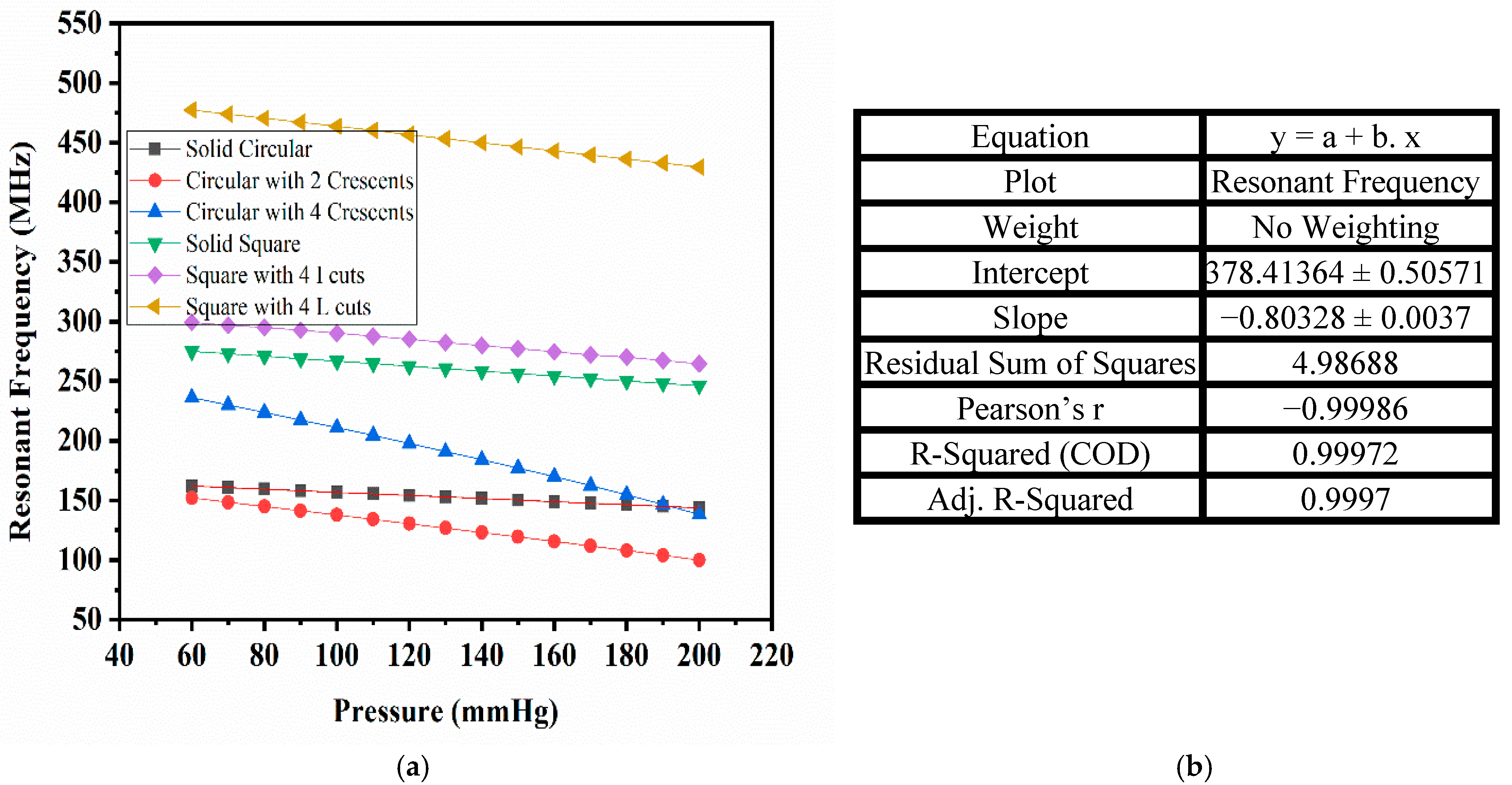
- The resonant frequency shift showed an exceptionally linear relationship with blood pressure (Pearson’s correlation coefficient of −0.99986 and R-squared value of 0.99972).
- The high sensitivity and linear response of the sensor make it an ideal contender for precise, real-time pressure-monitoring applications.
- The optimized sensor design can be used in passive wireless pressure-sensing techniques for continuous health monitoring, particularly in detecting in-stent restenosis.
Abstract
1. Introduction
2. Materials and Methods
2.1. Sensor Design and Biomaterial Properties
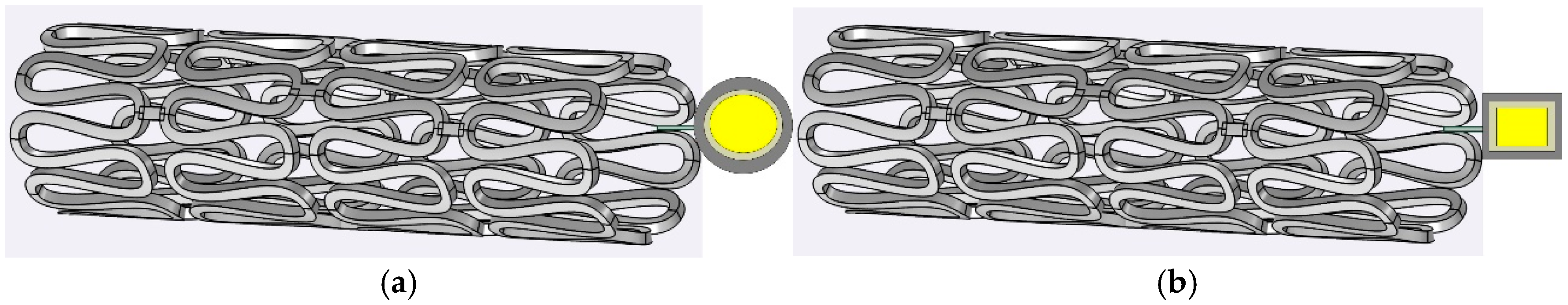
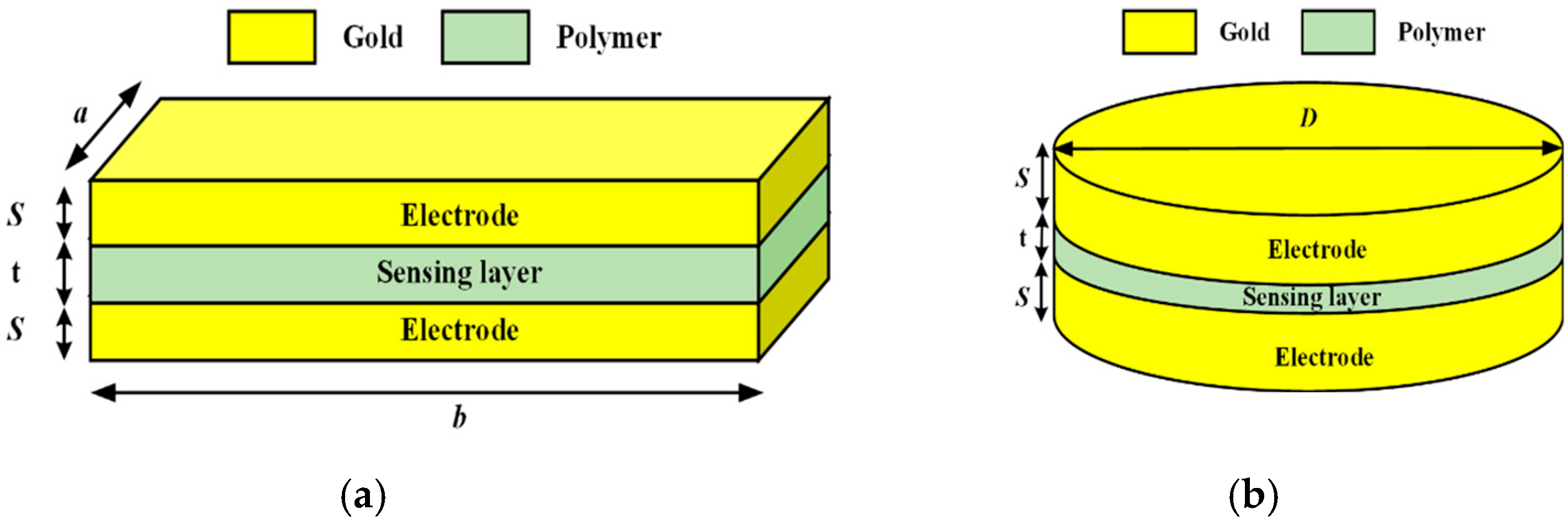
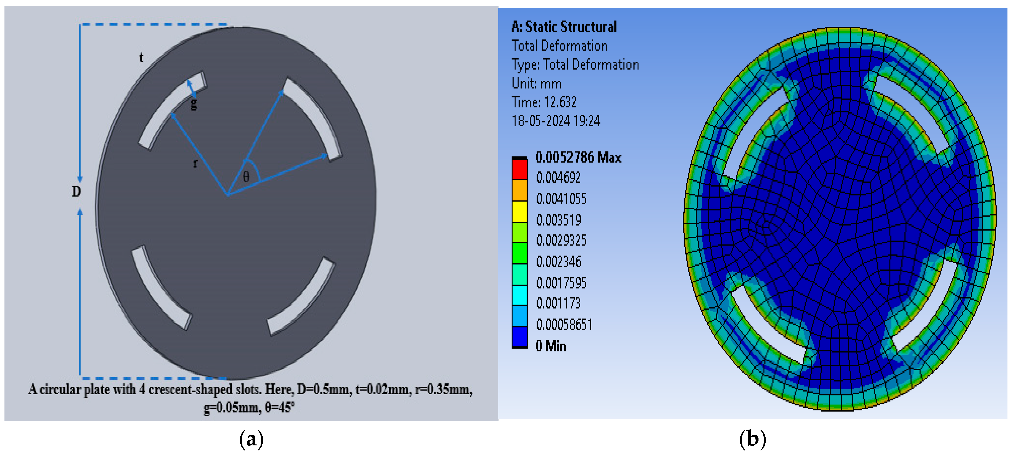
2.1.1. Sensor Structure
2.1.2. Biocompatible Material Selection
- Polydimethylsiloxane (PDMS)
- 2.
- Polyurethane Rubber
- 3.
- Silicone Rubber
3. Results and Discussion
3.1. Inductance Measurement of the Stent
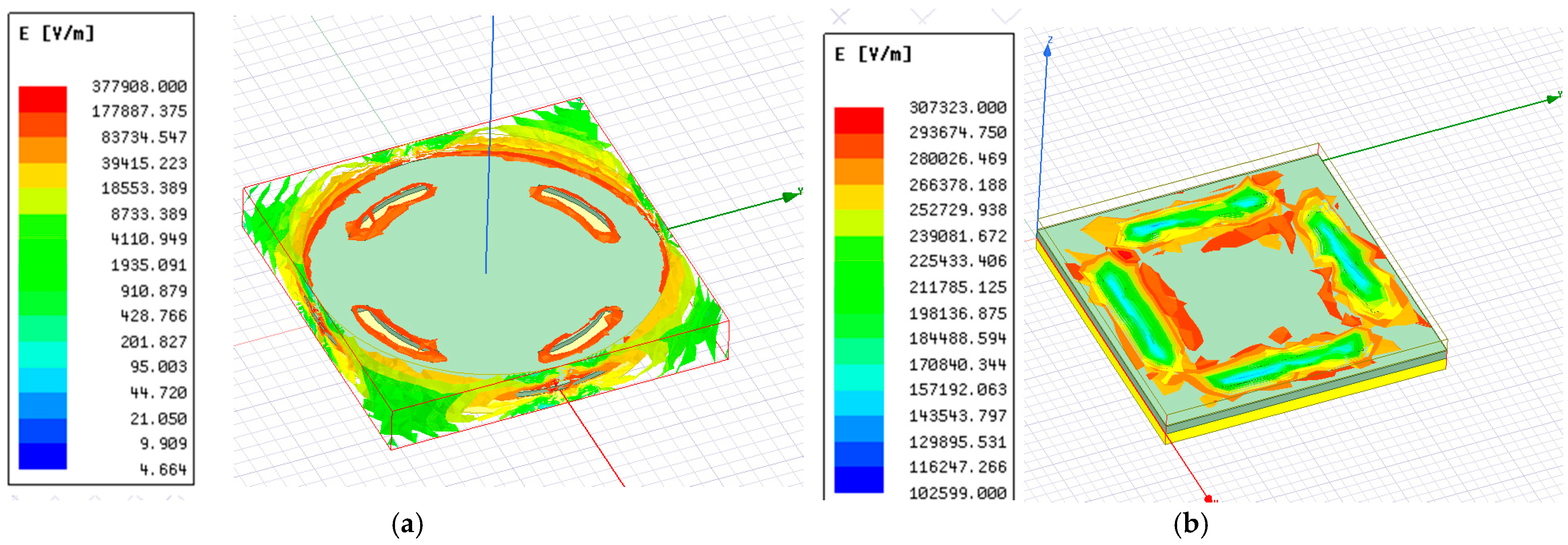
3.2. Capacitive Response of the Sensor
3.3. Shift in Resonant Frequency
4. Conclusions
Author Contributions
Funding
Institutional Review Board Statement
Informed Consent Statement
Data Availability Statement
Acknowledgments
Conflicts of Interest
References
- Alghrairi, M.; Sulaiman, N.; Mutashar, S. Health Care Monitoring and Treatment for Coronary Artery Diseases: Challenges and Issues. Sensors 2020, 20, 4303. [Google Scholar] [CrossRef] [PubMed]
- Scafa Udriște, A.; Niculescu, A.-G.; Grumezescu, A.M.; Bădilă, E. Cardiovascular Stents: A Review of Past, Current, and Emerging Devices. Materials 2021, 14, 2498. [Google Scholar] [CrossRef]
- Alfonso, F.; Coughlan, J.C.; Giacoppo, D.; Kastrati, A.; Byrne, R.B. Management of In-Stent Restenosis. EuroIntervention 2022, 18, e103–e123. [Google Scholar] [CrossRef] [PubMed]
- Li, M.; Hou, J.; Gu, X.; Weng, R.; Zhong, Z.; Liu, S. Incidence and Risk Factors of In-Stent Restenosis after Percutaneous Coronary Intervention in Patients from Southern China. Eur. J. Med. Res. 2022, 27, 12. [Google Scholar] [CrossRef]
- Chen, X.; Assadsangabi, B.; Hsiang, Y.; Takahata, K. Enabling Angioplasty-Ready “Smart” Stents to Detect In-Stent Restenosis and Occlusion. Adv. Sci. 2018, 5, 1700560. [Google Scholar] [CrossRef] [PubMed]
- Alghrairi, M.; Sulaiman, N.; Hasan, W.Z.W.; Jaafar, H.; Mutashar, S. Design a Wireless Pressure Sensor With an Ellipse and a Circular Shape to Monitor the Pressure Within the Coronary Artery. IEEE Access 2022, 10, 92158–92165. [Google Scholar] [CrossRef]
- Acharya, P.N.; Naduvinamani, S. Design and Simulation of MEMS Based Micro Pressure Sensor. In Proceedings of the 2012 COMSOL Conference, Bangalore, India, 1–2 November 2012; Available online: https://www.comsol.com/paper/download/152945/acharya_paper.pdf (accessed on 8 April 2025).
- Zhang, W.; Gu, G.; Ren, H.; Zhang, Z.; Zhang, Z.; Qin, H.; Zheng, M.; Du, Z.; Cheng, G. A Real-Time Self-Powered Wireless Pressure Sensing System Based on Capacitive Triboelectric Pressure Sensor. Nano Energy 2025, 136, 110729. [Google Scholar] [CrossRef]
- Wang, T.; Wang, C.; Zeng, Q.; Gu, G.; Wang, X.; Cheng, G.; Du, Z. A Real-Time, Self-Powered Wireless Pressure Sensing System with Efficient Coupling Energy Harvester, Sensing, and Communication Modules. Nano Energy 2024, 125, 109533. [Google Scholar] [CrossRef]
- Liu, G.; Lv, Z.; Batool, S.; Li, M.; Zhao, P.; Guo, L.; Wang, Y.; Zhou, Y.; Han, S. Biocompatible Material-Based Flexible Biosensors: From Materials Design to Wearable/Implantable Devices and Integrated Sensing Systems. Small 2023, 19, 2207879. [Google Scholar] [CrossRef]
- Ang, Y.X.; Ghazali, F.A.M.; Ali, M.S.M. Micromachined Shape Memory Alloy Active Stent with Wireless Monitoring and Re-Expansion Features. In Proceedings of the 2020 IEEE 33rd International Conference on Micro Electro Mechanical Systems (MEMS), Vancouver, BC, Canada, 18–22 January 2020; IEEE: Vancouver, BC, Canada, 2020; pp. 396–399. [Google Scholar]
- Ang, Y.X.; Khudzari, A.Z.M.; Ali, M.S.M. Non-Invasive Treatment for Coronary In-Stent Restenosis via Wireless Revascularization With Nitinol Active Stent. IEEE Trans. Biomed. Eng. 2021, 68, 3681–3689. [Google Scholar] [CrossRef]
- He, D.; Cui, Y.; Ming, F.; Wu, W. Advancements in Passive Wireless Sensors, Materials, Devices, and Applications. Sensors 2023, 23, 8200. [Google Scholar] [CrossRef]
- Ceron Hurtado, N.M.; Zarifi, M.H.; Daneshmand, M.; Aguilo Llobet, J. Flexible Microdisplacement Sensor for Wearable/Implantable Biomedical Applications. IEEE Sens. J. 2017, 17, 3873–3883. [Google Scholar] [CrossRef]
- Park, J.; Kim, J.-K.; Patil, S.; Park, J.-K.; Park, S.; Lee, D.-W. A Wireless Pressure Sensor Integrated with a Biodegradable Polymer Stent for Biomedical Applications. Sensors 2016, 16, 809. [Google Scholar] [CrossRef] [PubMed]
- Gong, S.; Schwalb, W.; Wang, Y.; Chen, Y.; Tang, Y.; Si, J.; Shirinzadeh, B.; Cheng, W. A Wearable and Highly Sensitive Pressure Sensor with Ultrathin Gold Nanowires. Nat. Commun. 2014, 5, 3132. [Google Scholar] [CrossRef] [PubMed]
- Yang, D.; Zhao, K.; Yang, R.; Zhou, S.; Chen, M.; Tian, H.; Qu, D. A Rational Design of Bio-Derived Disulfide CANs for Wearable Capacitive Pressure Sensor. Adv. Mater. 2024, 36, 2403880. [Google Scholar] [CrossRef]
- Miranda, I.; Souza, A.; Sousa, P.; Ribeiro, J.; Castanheira, E.M.S.; Lima, R.; Minas, G. Properties and Applications of PDMS for Biomedical Engineering: A Review. J. Funct. Biomater. 2021, 13, 2. [Google Scholar] [CrossRef]
- Trung, T.Q.; Lee, N. Flexible and Stretchable Physical Sensor Integrated Platforms for Wearable Human-Activity Monitoringand Personal Healthcare. Adv. Mater. 2016, 28, 4338–4372. [Google Scholar] [CrossRef]
- Yue, Y.; Liu, N.; Su, T.; Cheng, Y.; Liu, W.; Lei, D.; Cheng, F.; Ge, B.; Gao, Y. Self-Powered Nanofluidic Pressure Sensor with a Linear Transfer Mechanism. Adv. Funct. Mater. 2023, 33, 2211613. [Google Scholar] [CrossRef]
- Cho, E.; Chiu, L.L.Y.; Lee, M.; Naila, D.; Sadanand, S.; Waldman, S.D.; Sussman, D. Characterization of Mechanical and Dielectric Properties of Silicone Rubber. Polymers 2021, 13, 1831. [Google Scholar] [CrossRef]
- Guo, D.; Li, Y.; Zhou, Q.; Yu, Z.; Liu, X.; Dong, S.; Zhang, S.; Sung, H.-K.; Yao, Z.; Li, Y.; et al. Degradable, Biocompatible, and Flexible Capacitive Pressure Sensor for Intelligent Gait Recognition and Rehabilitation Training. Nano Energy 2024, 127, 109750. [Google Scholar] [CrossRef]
- Kim, H.; Rigo, B.; Wong, G.; Lee, Y.J.; Yeo, W.-H. Advances in Wireless, Batteryless, Implantable Electronics for Real-Time, Continuous Physiological Monitoring. Nano-Micro Lett. 2024, 16, 52. [Google Scholar] [CrossRef]
- Busnatu, Ș.S.; Niculescu, A.-G.; Bolocan, A.; Andronic, O.; Pantea Stoian, A.M.; Scafa-Udriște, A.; Stănescu, A.M.A.; Păduraru, D.N.; Nicolescu, M.I.; Grumezescu, A.M.; et al. A Review of Digital Health and Biotelemetry: Modern Approaches towards Personalized Medicine and Remote Health Assessment. J. Pers. Med. 2022, 12, 1656. [Google Scholar] [CrossRef]
- Khan, S.R.; Pavuluri, S.K.; Cummins, G.; Desmulliez, M.P.Y. Wireless Power Transfer Techniques for Implantable Medical Devices: A Review. Sensors 2020, 20, 3487. [Google Scholar] [CrossRef] [PubMed]
- Akar, O.; Akin, T.; Najafi, K. A Wireless Batch Sealed Absolute Capacitive Pressure Sensor. Sens. Actuators Phys. 2001, 95, 29–38. [Google Scholar] [CrossRef]
- Iqbal, M.; Sultan, S.; Qasaimeh, M.A. Novel Capacitive MEMS Sensor for Monitoring In-Stent Restenosis. In Proceedings of the 2019 41st Annual International Conference of the IEEE Engineering in Medicine and Biology Society (EMBC), Berlin, Germany, 23–27 July 2019; IEEE: Berlin, Germany, 2019; pp. 368–371. [Google Scholar]
- Cai, M.-X.; Yang, Y.-J. A Wireless Cardiovascular Pressure Sensor Based on an Iontronic Film with High Sensitivity. In Proceedings of the 2021 IEEE 34th International Conference on Micro Electro Mechanical Systems (MEMS), Gainesville, FL, USA, 25–29 January 2021; IEEE: Gainesville, FL, USA, 2021; pp. 135–138. [Google Scholar]
- Bulbul, A.; Kim, H. Pressure Sensor Embedded Inductive Coil Toward a Wireless Pressure Sensing Stent. J. Microelectromechanical Syst. 2021, 30, 224–233. [Google Scholar] [CrossRef]
- Bijender; Kumar, A. Flexible and Wearable Capacitive Pressure Sensor for Blood Pressure Monitoring. Sens. Bio-Sens. Res. 2021, 33, 100434. [Google Scholar] [CrossRef]
- Tran, P.A.; Fox, K.; Tran, N. Novel Hierarchical Tantalum Oxide-PDMS Hybrid Coating for Medical Implants: One Pot Synthesis, Characterization and Modulation of Fibroblast Proliferation. J. Colloid Interface Sci. 2017, 485, 106–115. [Google Scholar] [CrossRef]
- Victor, A.; Ribeiro, J.E.; Araújo, F.F. Study of PDMS Characterization and Its Applications in Biomedicine: A Review. J. Mech. Eng. Biomech. 2019, 4, 1–9. [Google Scholar] [CrossRef]
- Zdrahala, R.J.; Zdrahala, I.J. Biomedical Applications of Polyurethanes: A Review of Past Promises, Present Realities, and a Vibrant Future. J. Biomater. Appl. 1999, 14, 67–90. [Google Scholar] [CrossRef]
- Shin, E.J.; Choi, S.M. Advances in Waterborne Polyurethane-Based Biomaterials for Biomedical Applications. In Novel Biomaterials for Regenerative Medicine; Chun, H.J., Park, K., Kim, C.-H., Khang, G., Eds.; Advances in Experimental Medicine and Biology; Springer: Singapore, 2018; Volume 1077, pp. 251–283. ISBN 978-981-13-0946-5. [Google Scholar]
- Zare, M.; Ghomi, E.R.; Venkatraman, P.D.; Ramakrishna, S. Silicone-based Biomaterials for Biomedical Applications: Antimicrobial Strategies and 3D Printing Technologies. J. Appl. Polym. Sci. 2021, 138, 50969. [Google Scholar] [CrossRef]


| Sensor | Parameter | Value |
|---|---|---|
| Circular | Electrode diameter (D) | 1 mm |
| Electrode thickness (S) | 20 µm | |
| Sensing layer thickness (t) | 20 µm | |
| Electrode material | Gold | |
| Sensing material | PDMS, polyurethane rubber, and silicone rubber | |
| Sensing layer dielectric constant | 2.69, 3, and 3.7, respectively | |
| Electrode bulk conductivity (S/m) | 2.5 × 10⁻¹⁴, 1 × 10⁻¹¹, and 3.47 × 10⁻⁴, respectively | |
| Square | Electrode length (a) | 0.5 mm |
| Electrode width (b) | 0.5 mm | |
| Electrode thickness (S) | 20 µm | |
| Sensing layer thickness (t) | 20 µm | |
| Electrode material | Gold | |
| Sensing material | PDMS, polyurethane rubber, and silicone rubber | |
| Sensing layer dielectric constant | 2.69, 3, and 3.7, respectively | |
| Electrode bulk conductivity (S/m) | 2.5 × 10⁻¹⁴, 1 × 10⁻¹¹, and 3.47 × 10⁻⁴, respectively |
| Parameter | [27] (Square with 4 Straight Slots, Poly-Si) | Proposed Design (Circular with 2 Crescents, PDMS) | Level of Superiority in Proposed Design |
|---|---|---|---|
| Sensitivity | 1.05 fF/mmHg | 10.68 fF/mmHg | 10.2× higher |
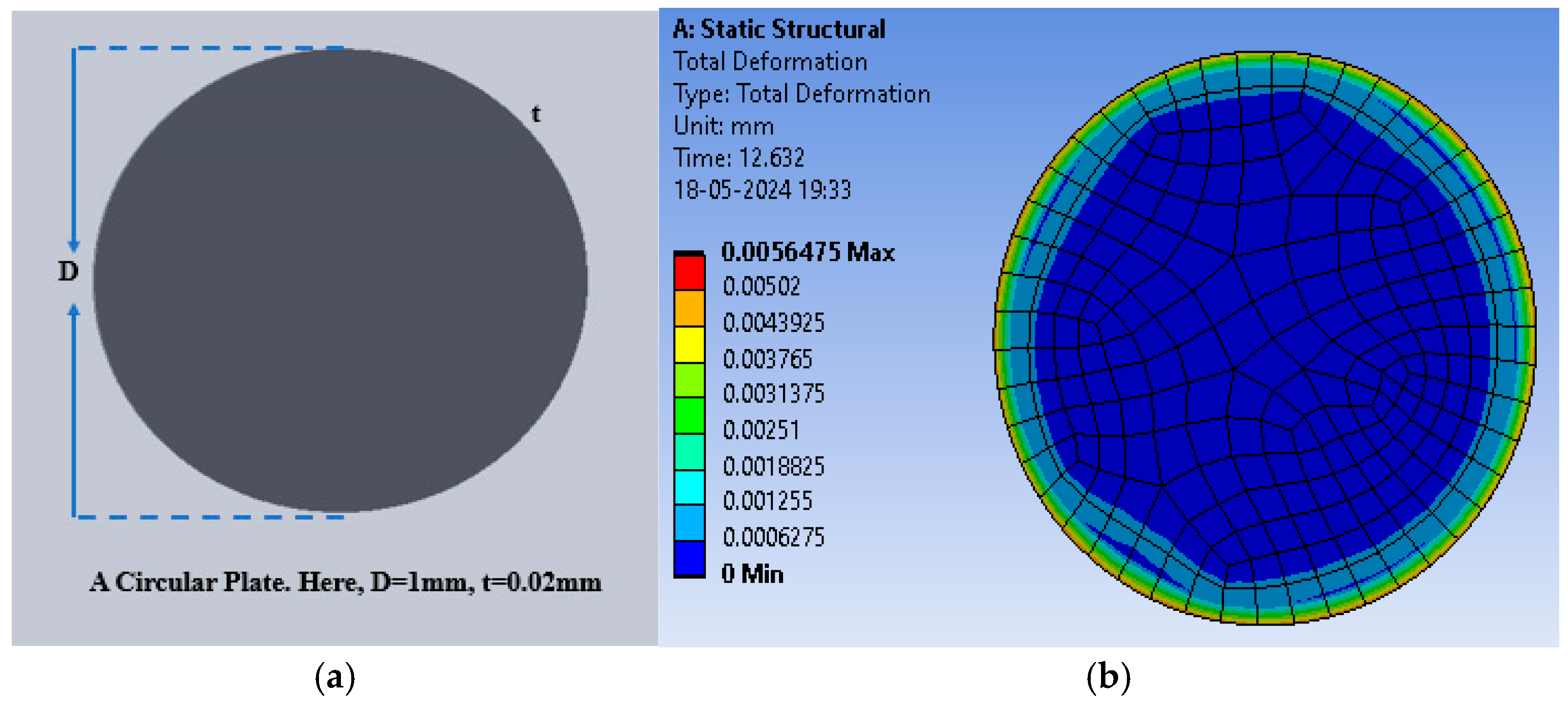
| Maximum Deflection | 8.09 μm | 1.35 × 10⁻² mm | 1.7× higher |
| Initial Capacitance | 0.195 pF | 0.892 pF | 4.6× higher |
| Final Capacitance | 0.363 pF | 2.733 pF | 7.5× higher |
| Capacitance change | 0.168 pF | 1.841 pF | 11.0× higher |
| S. No. | Dielectric Material | Dielectric Constant | Bulk Conductivity (S/m) |
|---|---|---|---|
| 1 | PDMS | 2.69 | 2.5 × 10⁻¹⁴ |
| 2 | Polyurethane Rubber | 3.0 | 1 × 10⁻¹¹ |
| 3 | Silicone Rubber | 3.70 | 3.47 × 10⁻⁴ |
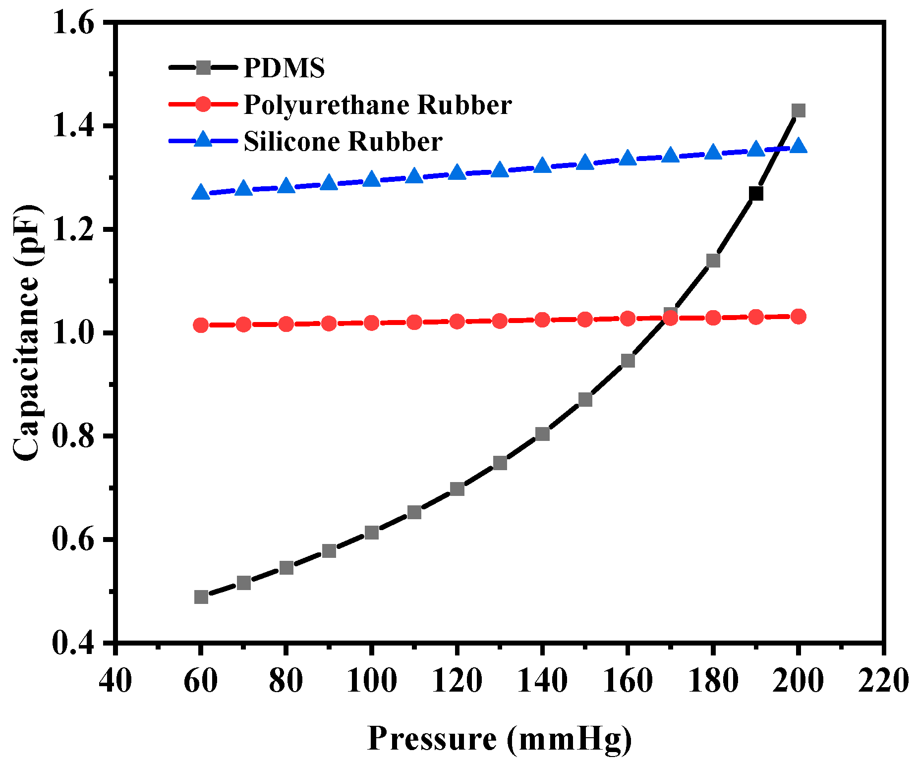
| Sensor Type | Applied Pressure (mmHg) | Theoretical Capacitance Value (pF) | Simulated Capacitance Value (pF) | Mean Deviation in Capacitance, ΔC (pF) |
|---|---|---|---|---|
| Solid Circular-Shaped Electrode | 0 | 0.93 | 0.95 | 0.02 |
| 60 | 1.02 | 1.04 | 0.02 | |
| 200 | 1.30 | 1.32 | 0.02 | |
| Solid Square-Shaped Electrode | 0 | 0.29 | 0.33 | 0.04 |
| 60 | 0.32 | 0.36 | 0.04 | |
| 200 | 0.40 | 0.44 | 0.04 |
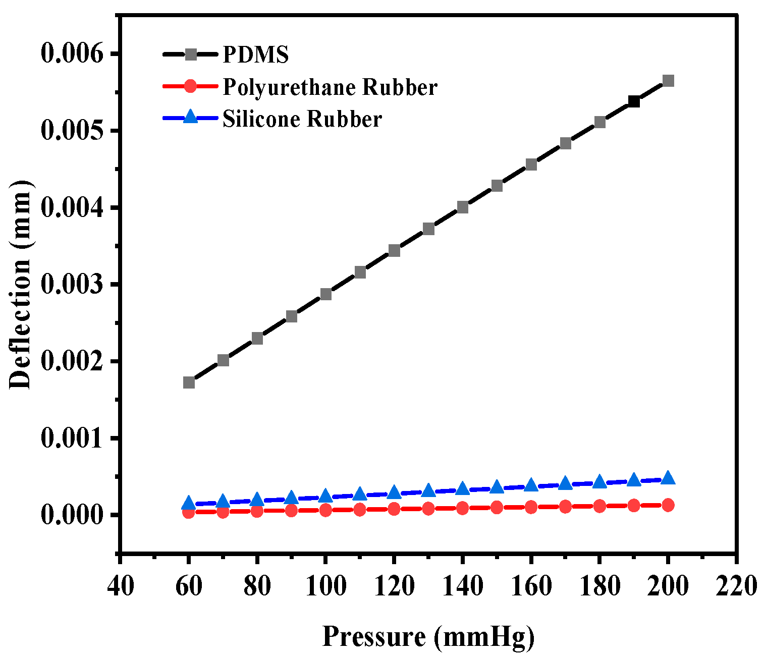
| Plate Type | Slot Type | Plate Material | Slot Inner Arc/Length (mm) | Slot Width (mm) | Deflection Maximum (mm) | Capacitance Without Deflection (pF) | Capacitance With Maximum Deflection (pF) |
|---|---|---|---|---|---|---|---|
| Circular | No slots | PDMS | -- | -- | 5.648 × 10⁻³ | 0.95063 | 1.324 |
| Polyurethane Rubber | -- | -- | 1.3000 × 10⁻⁴ | 1.0585 | 1.0656 | ||
| Silicone Rubber | -- | -- | 4.6210 × 10⁻⁴ | 1.4055 | 1.4386 | ||
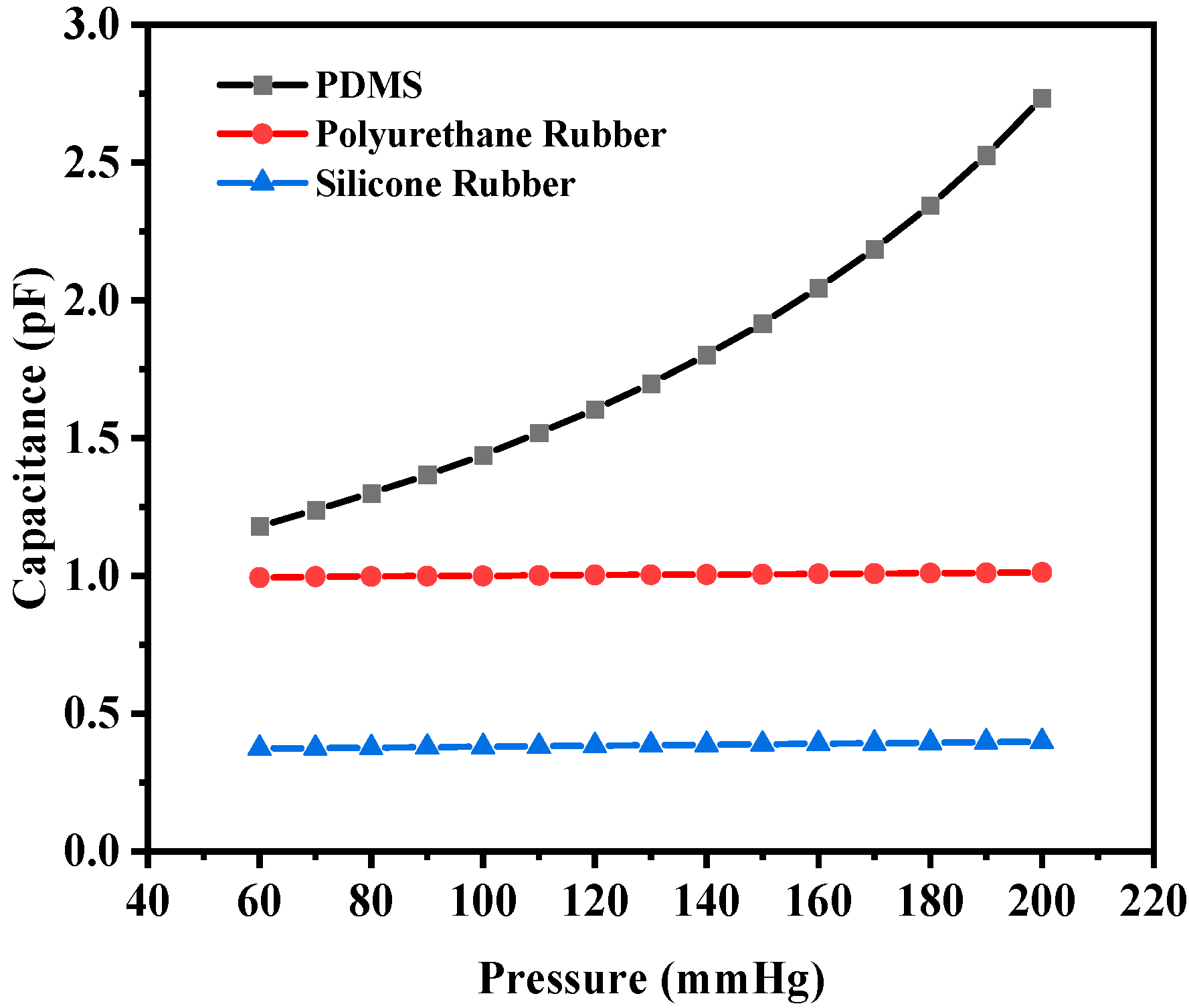
| Two Crescents | PDMS | 0.7330 | 0.05 | 1.35 × 10⁻² | 0.89248 | 2.7334 | |
| Polyurethane Rubber | 0.7330 | 0.05 | 4.56 × 10⁻⁴ | 0.98935 | 1.0127 | ||
| Silicone Rubber | 0.7330 | 0.05 | 1.8219 × 10⁻³ | 0.36336 | 0.3987 | ||
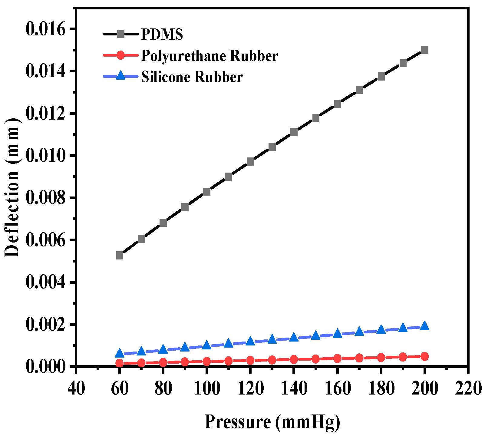
| Four Crescents | PDMS | 0.2749 | 0.05 | 1.5013 × 10⁻² | 0.36423 | 1.4302 | |
| Polyurethane Rubber | 0.2749 | 0.05 | 4.76 × 10⁻⁴ | 1.0072 | 1.0314 | ||
| Silicone Rubber | 0.2749 | 0.05 | 1.89 × 10⁻³ | 1.2321 | 1.3582 | ||
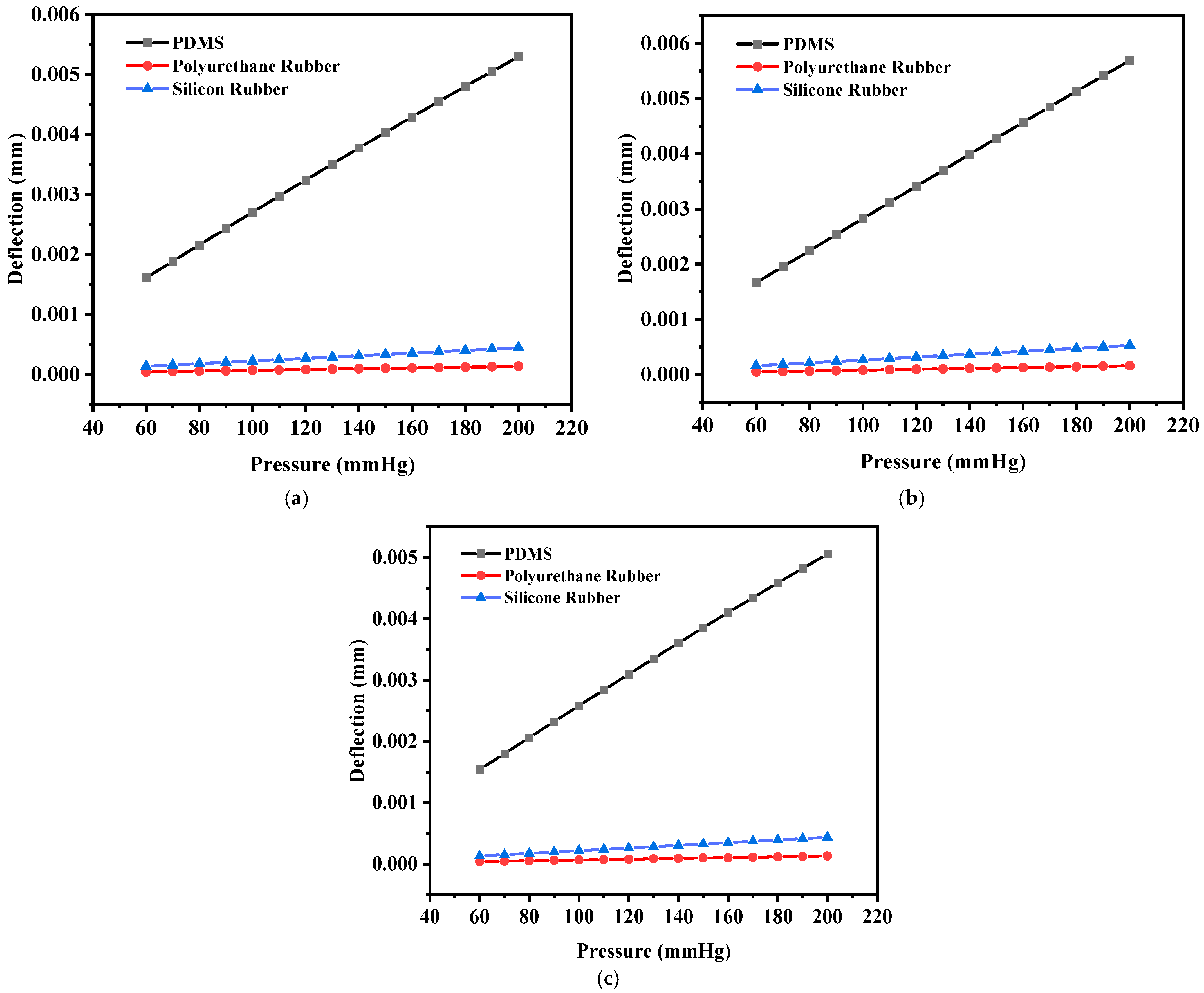
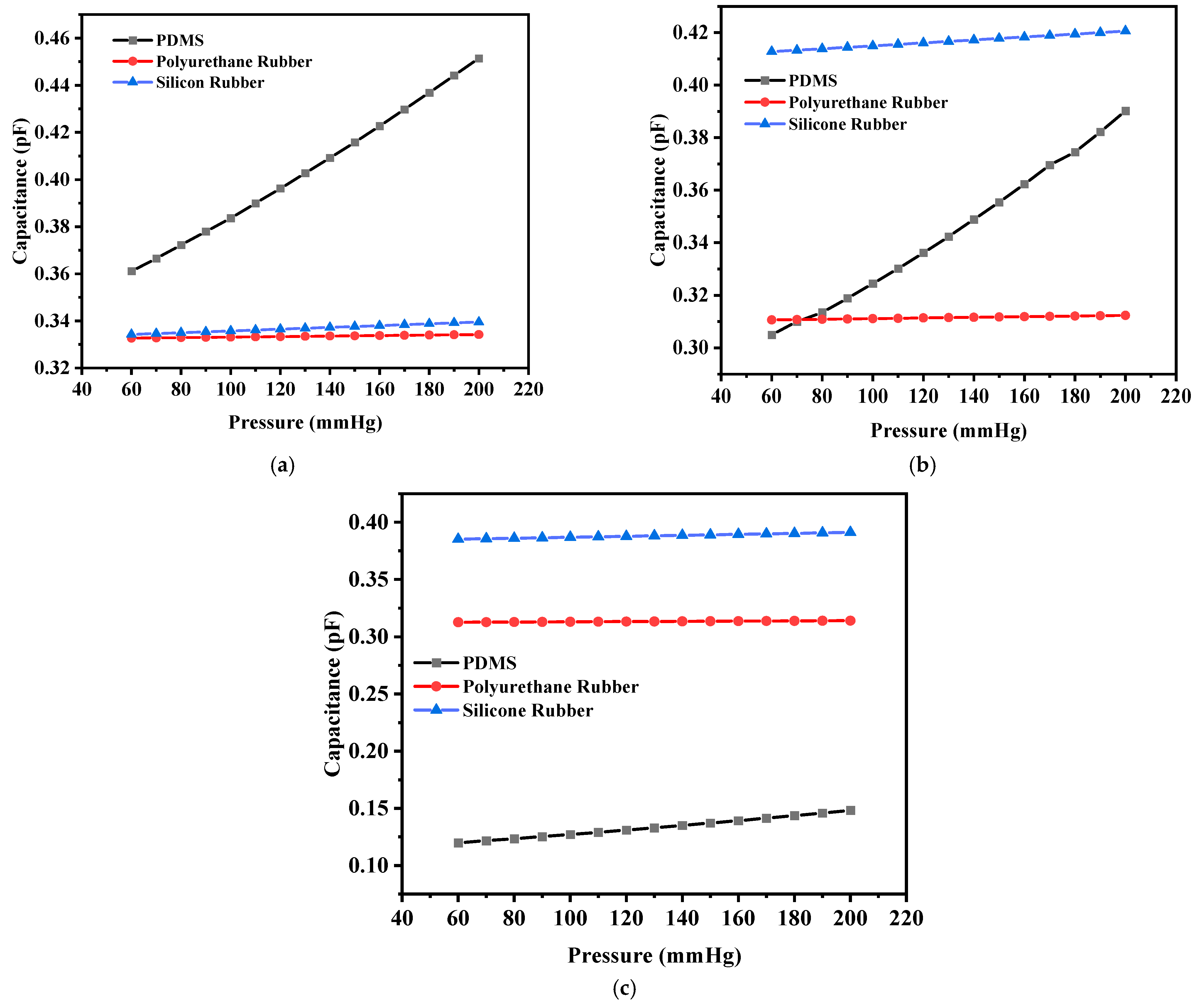
| Square | No slots | PDMS | -- | -- | 5.29 × 10⁻³ | 0.33203 | 0.45144 |
| Polyurethane Rubber | -- | -- | 1.32 × 10⁻⁴ | 0.33203 | 0.33424 | ||
| Silicone Rubber | -- | -- | 4.43 × 10⁻⁴ | 0.33203 | 0.33955 | ||
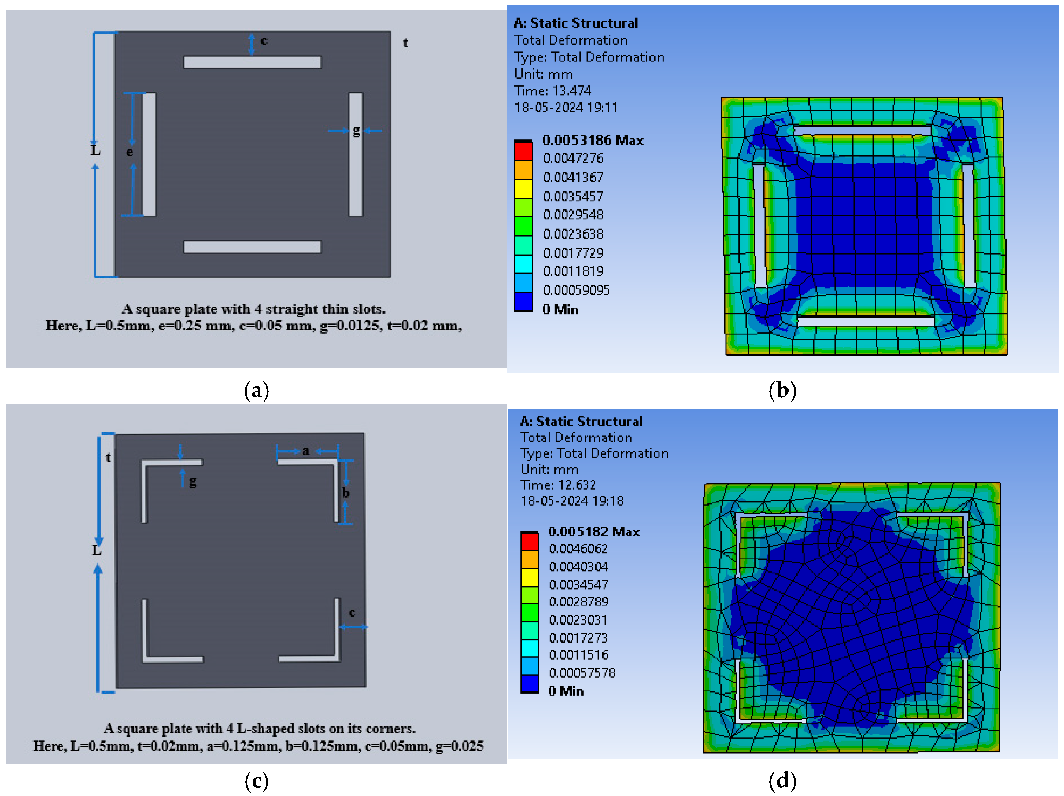
| Four I-Shaped | PDMS | 0.25 | 0.0125 | 5.69 × 10⁻³ | 0.27902 | 0.39023 | |
| Polyurethane Rubber | 0.25 | 0.0125 | 1.58 × 10⁻⁴ | 0.3099 | 0.31236 | ||
| Silicone Rubber | 0.25 | 0.0125 | 5.2796 × 10⁻⁴ | 0.40951 | 0.42061 | ||
| Four L-Shaped | PDMS | 0.225 | 0.025 | 5.0606 × 10⁻³ | 0.11068 | 0.14817 | |
| Polyurethane Rubber | 0.225 | 0.025 | 1.2942 × 10⁻⁴ | 0.31211 | 0.31414 | ||
| Silicone Rubber | 0.225 | 0.025 | 4.3597 × 10⁻⁴ | 0.38261 | 0.39114 |
| Sensor | Slots | Dielectric Material | Sensitivity (fF/mmHg) |
|---|---|---|---|
| Circular capacitive sensor | 0 | PDMS | 2.01 |
| Polyurethane rubber | 3.87857 × 10⁻² | ||
| Silicone rubber | 1.85429 × 10⁻¹ | ||
| 2 | PDMS | 10.68 | |
| Polyurethane rubber | 1.19443 × 10⁻¹ | ||
| Silicone rubber | 1.79943 × 10⁻¹ | ||
| 4 | PDMS | 6.23 | |
| Polyurethane rubber | 1.24429 × 10⁻¹ | ||
| Silicone rubber | 6.46071 × 10⁻¹ | ||
| Square capacitive sensor | 0 | PDMS | 6.46925 × 10⁻¹ |
| Polyurethane rubber | 1.10536 × 10⁻² | ||
| Silicone rubber | 3.78679 × 10⁻² | ||
| 4 | PDMS | 6.12496 × 10⁻¹ | |
| Polyurethane rubber | 1.235 × 10⁻² | ||
| Silicone rubber | 5.60036 × 10⁻² | ||
| 8 | PDMS | 2.02011 × 10⁻¹ | |
| Polyurethane rubber | 1.01679 × 10⁻² | ||
| Silicone rubber | 4.29036 × 10⁻² |
| Reference No. | Coil Shape | Inductance | Material of Sensor | Sensor Shape | Dimension of Sensor | Frequency | Sensitivity | Pressure Range |
|---|---|---|---|---|---|---|---|---|
| [24] | Stent Length: 7.2 mm | 180 nH | Copper, silicon wafer, glycerol | Circular | Hydraulic chamber: 400 × 100 × 12 µm3 | 100 KHz–3 GHz | 0.052 fF/mmHg | 0–300 mmHg |
| [6] | Stent Length: 30 mm | 350 nH | Gold, polyimide, silicon nitride | Ellipse | 750 × 424 × 200 µm3 | 26.78–27.09 MHz | 7.73 ff/mmHg | 0–240 mmHg |
| [6] | Stent Length: 30 mm | 350 nH | Gold, polyimide, silicon nitride | Circular | 564 × 564 × 200 µm3 | 26.78–27.09 MHz | 9.94 ff/mmHg | 0–240 mmHg |
| [21] | Planar | 1.2 µH | Glass, gold, silicon | Rectangular | 2.6 × 1.6 mm2 | 95–103 MHz | 120 KHz/mmHg | 0–50 mmHg |
| [22] | Stent Length: 20 mm | 530 nH | Stainless steel, parylene C | Square | 1.5 × 1.5 × 0.2 mm3 | 50 MHz | 146 ppm/mmHg | 0–250 mmHg |
| Present Work | Stent Length: 30 mm | 927 nH | Gold, PDMS | Circular | 1000 × 1000 × 20 µm3 | 100 KHz–110 MHz | 10.68 ff/mmHg | 60–200 mmHg |
Disclaimer/Publisher’s Note: The statements, opinions and data contained in all publications are solely those of the individual author(s) and contributor(s) and not of MDPI and/or the editor(s). MDPI and/or the editor(s) disclaim responsibility for any injury to people or property resulting from any ideas, methods, instructions or products referred to in the content. |
© 2025 by the authors. Licensee MDPI, Basel, Switzerland. This article is an open access article distributed under the terms and conditions of the Creative Commons Attribution (CC BY) license (https://creativecommons.org/licenses/by/4.0/).
Share and Cite
Alam, M.S.T.; Urooj, S.; Ansari, A.Q.; Arif, A. Design and Performance Assessment of Biocompatible Capacitive Pressure Sensors with Circular and Square Geometries Using ANSYS Workbench. Sensors 2025, 25, 2423. https://doi.org/10.3390/s25082423
Alam MST, Urooj S, Ansari AQ, Arif A. Design and Performance Assessment of Biocompatible Capacitive Pressure Sensors with Circular and Square Geometries Using ANSYS Workbench. Sensors. 2025; 25(8):2423. https://doi.org/10.3390/s25082423
Chicago/Turabian StyleAlam, Md Shams Tabraiz, Shabana Urooj, Abdul Quaiyum Ansari, and Areiba Arif. 2025. "Design and Performance Assessment of Biocompatible Capacitive Pressure Sensors with Circular and Square Geometries Using ANSYS Workbench" Sensors 25, no. 8: 2423. https://doi.org/10.3390/s25082423
APA StyleAlam, M. S. T., Urooj, S., Ansari, A. Q., & Arif, A. (2025). Design and Performance Assessment of Biocompatible Capacitive Pressure Sensors with Circular and Square Geometries Using ANSYS Workbench. Sensors, 25(8), 2423. https://doi.org/10.3390/s25082423