
Development of an Ankle Exoskeleton: Design, Modeling, and Testing

 ,
, 
 , ,
, ,  , and
, and
Abstract
1. Introduction
2. Materials and Methods
2.1. Study of Biomechanical Characteristics of Ankle Joint
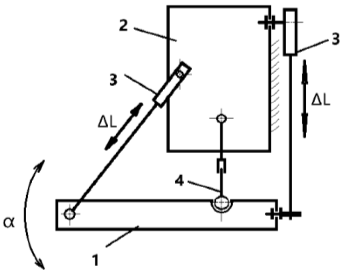
2.2. Kinematics and Performance of Exoskeleton System
- n—number of links;
- p5—number of fifth-class couples (single-movement couples);
- p4—number of pairs of the fourth class (two movable pairs).
- (foot platform, shank platform, actuator, and fixed ground);
- (two prismatic actuators);
- (one spherical joint).
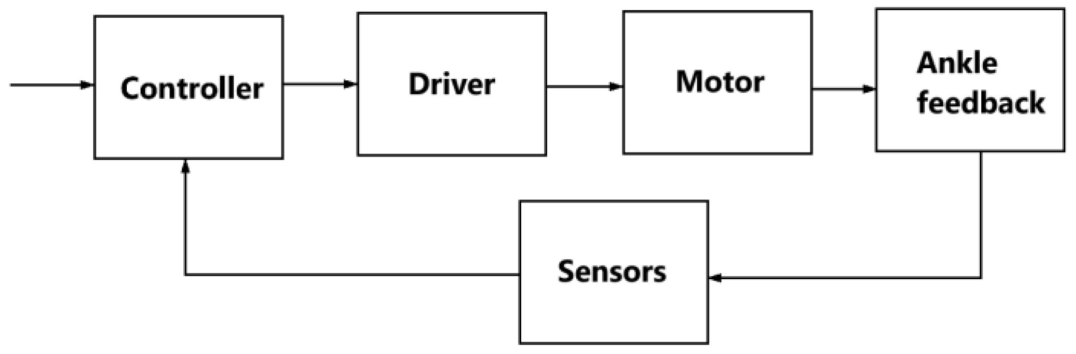
2.3. Development of Exoskeleton Control System
3. Results
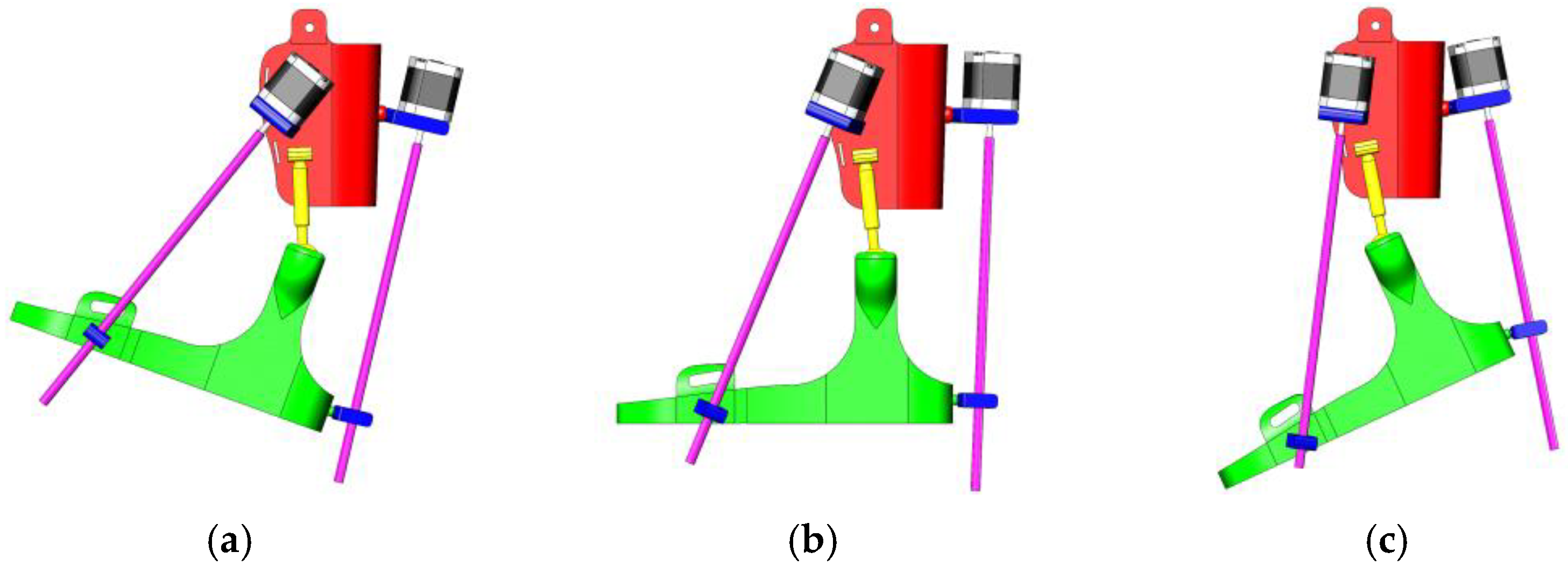
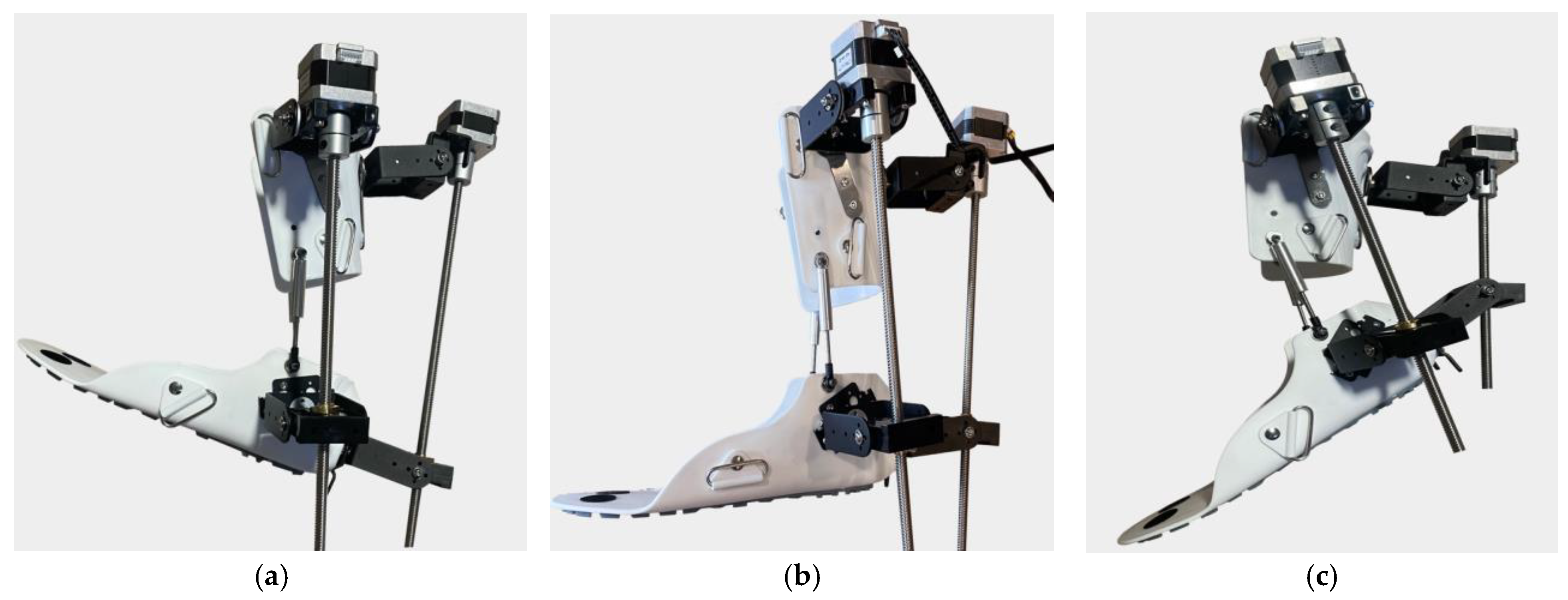
- (a)
- Dorsiflexion;
- (b)
- Neutral position;
- (c)
- Plantar flexion.
- (a)
- Dorsiflexion Phase: In the dorsiflexion state, the foot is lifted upwards by an angle of 15°, which is a crucial part of natural foot movement. This movement actively engages the tibialis anterior muscles, stimulating foot elevation and expanding the patient’s range of motion. Additionally, this motion is aimed at restoring muscle activity and improving the motor functions of the foot.
- (b)
- Neutral Position: The neutral position represents the natural resting state of the foot, where the ankle joint is positioned at a 90° angle. This position ensures stability and serves as the primary support phase during rehabilitation. Throughout the rehabilitation process, this position helps the joint and muscles adapt to normal conditions, while the exoskeleton assists in activating the patient’s leg muscles.
- (c)
- Plantar Flexion Phase: In the plantar flexion state, the foot is lowered by 20°, mimicking the propulsion phase of walking. This movement is designed to activate the posterior leg muscles and enhance their flexibility. During rehabilitation, such movements help strengthen the patient’s leg muscles, increase movement amplitude, and improve limb coordination.
- (a)
- Inward Adduction Position—Inversion: In this position, the foot tilts inward, raising the medial (inner) side of the sole. This movement is used to strengthen the internal ligaments and muscles of the foot, improving joint stability.
- (b)
- Neutral Position—Resting State: In this configuration, the ankle joint remains in its natural balanced state, with the foot fully relaxed. This position serves as the initial and intermediate reference point during rehabilitation exercises.
- (c)
- Outward Adduction Position—Eversion: In this case, the foot tilts outward, raising the lateral (outer) side of the sole. This movement helps activate the external foot muscles and ensures a full range of motion, essential for restoring ankle mobility.
- (a)
- Valgus (Abduction) Position: In this position, the foot tilts outward within a range of 5–15°, deviating laterally relative to the Y-axis. This movement stretches the inner ligaments of the foot and helps improve lateral stability.
- (b)
- Neutral Position: In this configuration, the ankle joint remains in a naturally balanced state, with the foot in a neutral position. This serves as the starting and intermediate reference point during rehabilitation.
- (c)
- Varus (Adduction) Position: Here, the foot tilts inward within a range of 5–15°, deviating medially relative to the Y-axis. This movement restores medial stability and ensures a full range of motion for the foot’s lateral movements.
4. Discussion
5. Conclusions
Author Contributions
Funding
Institutional Review Board Statement
Informed Consent Statement
Data Availability Statement
Conflicts of Interest
References
- World Health Organization (WHO). Rehabilitation: Key Facts. Available online: https://www.who.int/news-room/fact-sheets/detail/rehabilitation (accessed on 22 April 2024).
- World Health Organization (WHO). Rehabilitation 2030 Initiative: Meeting Report, Geneva, Switzerland 10–11 July 2023. Available online: https://iris.who.int/bitstream/handle/10665/376162/9789240087392-eng.pdf?sequence=1 (accessed on 19 March 2025).
- Gao, M.; Wang, Z.; Pang, Z.; Sun, J.; Li, J.; Li, S.; Zhang, H. Electrically Driven Lower Limb Exoskeleton Rehabilitation Robot Based on Anthropomorphic Design. Machines 2022, 10, 266. [Google Scholar] [CrossRef]
- Ye, H.; Khan, M.N.; Shao, Z.F.; Pan, Y. Development of a Novel Cable-Driven Parallel Robot for Full-Cycle Ankle Rehabilitation. Mechatronics 2024, 101, 103210. [Google Scholar] [CrossRef]
- Mo, F.; Zhang, Q.; Zhang, H.; Long, J.; Wang, Y.; Chen, G.; Ye, J. A Simulation-Based Framework with a Proprioceptive Musculoskeletal Model for Evaluating the Rehabilitation Exoskeleton System. Comput. Methods Progr. Biomed. 2021, 208, 106270. [Google Scholar] [CrossRef]
- Cardona, M.; Ordoñez-Avila, J.L. Current Status and Perspectives of Lower Limb Exoskeleton Rehabilitation Robots. In Rehabilitation Robotics and Healthcare Devices; Cardona, M., Ed.; Academic Press: Cambridge, MA, USA, 2025; pp. 195–209. ISBN 9780443215056. [Google Scholar] [CrossRef]
- Hussain, S.; Ficuciello, F. Advancements in Soft Wearable Robots: A Systematic Review of Actuation Mechanisms and Physical Interfaces. IEEE Trans. Med. Robot. Bionics 2024, 6, 903–929. [Google Scholar] [CrossRef]
- Gomez-Vargas, D.; Ballen-Moreno, F.; Rodriguez-Guerrero, C.; Munera, M.; Cifuentes, C.A. Experimental Characterization of the T-FLEX Ankle Exoskeleton for Gait Assistance. Mechatronics 2021, 78, 102608. [Google Scholar] [CrossRef]
- Arauz, P.G.; Chavez, G.; Reinoso, V.; Ruiz, P.; Ortiz, E.; Cevallos, C.; Garcia, G. Influence of a Passive Exoskeleton on Kinematics, Joint Moments, and Self-Reported Ratings during a Lifting Task. J. Biomech. 2024, 162, 111886. [Google Scholar] [CrossRef] [PubMed]
- Chen, J.; Huang, Y.; Guo, X.; Zhou, S.; Jia, L. Parameter Identification and Adaptive Compliant Control of Rehabilitation Exoskeleton Based on Multiple Sensors. Measurement 2020, 159, 107765. [Google Scholar] [CrossRef]
- Salcido, E.A.A.; Centeno-Barreda, D.; Rosales, Y.; Lopéz-Gutiérrez, R.; Salazar, S.; Lozano, R. Design of a Lower Limb Exoskeleton: Robust Control, Simulation and Experimental Results. Algorithms 2023, 16, 449. [Google Scholar] [CrossRef]
- Jiang, J.; Chen, P.; Peng, J.; Qiao, X.; Zhu, F.; Zhong, J. Design and Optimization of Lower Limb Rehabilitation Exoskeleton with a Multiaxial Knee Joint. Biomimetics 2023, 8, 156. [Google Scholar] [CrossRef]
- Ostraich, B.; Riemer, R. Design of a Multi-Joint Passive Exoskeleton for Vertical Jumping Using Optimal Control. IEEE Trans. Neural Syst. Rehabil. Eng. 2022, 30, 2815–2823. [Google Scholar] [CrossRef]
- Wang, X.; Qiu, J.; Fong, D.T.P. The Applications of Wearable Devices in the Rehabilitation of Ankle Injuries: A Systematic Review and Meta-Analysis. Med. Nov. Technol. Devices 2023, 17, 100210. [Google Scholar] [CrossRef]
- Birlescu, I.; Tohanean, N.; Vaida, C.; Gherman, B.; Neguran, D.; Horsia, A.; Tucan, P.; Condurache, D.; Pisla, D. Modeling and Analysis of a Parallel Robotic System for Lower Limb Rehabilitation with Predefined Operational Workspace. Mech. Mach. Theory 2024, 198, 105674. [Google Scholar] [CrossRef]
- He, L.; Xu, C.; Guan, X. Design Methodology and Experimental Study of a Lower Extremity Soft Exosuit. Electronics 2023, 12, 2502. [Google Scholar] [CrossRef]
- Kenas, F.; Saadia, N.; Ababou, A.; Ababou, N.; Zabat, M.; BenSiSaid, K. Neural Network-Based Estimation of Lower Limb Joint Kinematics: A Minimally Intrusive Approach for Gait Analysis. Med. Nov. Technol. Devices 2024, 23, 100318. [Google Scholar] [CrossRef]
- Ajjanaromvat, N.; Parnichkun, M. Trajectory Tracking Using Online Learning LQR with Adaptive Learning Control of a Leg-Exoskeleton for Disorder Gait Rehabilitation. Mechatronics 2018, 51, 85–96. [Google Scholar] [CrossRef]
- Shiraishi, Y.; Okamoto, S.; Yamada, N.; Hoshino, S.; Iwasaki, M.; Noritake, K.; Takahashi, K. Pneumatically-Driven Stretching Machine for Ankle Dorsiflexion: Safety Concepts and Effectiveness Test Involving Healthy Young Subjects. Robomech J. 2020, 7, 10. [Google Scholar] [CrossRef]
- Xu, C.; Zhou, Y.; Ji, J.; Wei, C. An Ankle Joint Flexion and Extension Movement-Monitoring Device Based on Pressure Sensors. Micromachines 2023, 14, 2141. [Google Scholar] [CrossRef]
- Gonçalves, R.S.; Rodrigues, L.A.O.; Humbert, R.; Carbone, G. A User-Friendly Nonmotorized Device for Ankle Rehabilitation. Robotics 2023, 12, 32. [Google Scholar] [CrossRef]
- Pan, C.-T.; Lee, M.-C.; Huang, J.-S.; Chang, C.-C.; Hoe, Z.-Y.; Li, K.-M. Active Assistive Design and Multiaxis Self-Tuning Control of a Novel Lower Limb Rehabilitation Exoskeleton. Machines 2022, 10, 318. [Google Scholar] [CrossRef]
- Meng, Q.; Liu, G.; Xu, X.; Meng, Q.; Yu, H. Design and Analysis of a Supine Ankle Rehabilitation Robot for Early Stroke Recovery. Machines 2023, 11, 787. [Google Scholar] [CrossRef]
- Nursultan, Z.; Titov, A.; Ceccarelli, M.; Balbayev, G. Design and Performance of a Motion-Assisting Device for Ankle. In Advances in Asian Mechanism and Machine Science; Khang, N.V., Hoang, N.Q., Ceccarelli, M., Eds.; Springer: Cham, Switzerland, 2022; Volume 113. [Google Scholar] [CrossRef]
- Zhetenbayev, N.; Sergazin, G.; Tursunbayeva, G.; Uzbekbayev, A.; Kyrykbayev, B. Development of a Control Algorithm for an Ankle Joint Rehabilitation Device. In Artificial Intelligence in Healthcare; Lecture Notes in Computer Science; Xie, X., Styles, I., Powathil, G., Ceccarelli, M., Eds.; Springer: Cham, Switzerland, 2024; Volume 14975. [Google Scholar] [CrossRef]
- Sergazin, G.; Zhetenbayev, N.; Tursunbayeva, G.; Uzbekbayev, A.; Sarina, A.; Nurgizat, Y.; Nussibaliyeva, A. Design, Simulation and Functional Testing of a Novel Ankle Exoskeleton with 3DOFs. Sensors 2024, 24, 6160. [Google Scholar] [CrossRef] [PubMed]
- Ding, B.; Li, X.; Li, Y. Configuration Design and Experimental Verification of a Variable Constant-Force Compliant Mechanism. Robotica 2022, 40, 3463–3475. [Google Scholar] [CrossRef]
- Nursultan, Z.; Ceccarelli, M.; Balbayev, G. Design and Performance Analysis of Ankle Joint Exoskeleton. In New Trends in Medical and Service Robotics; Tarnita, D., Dumitru, N., Pisla, D., Carbone, G., Geonea, I., Eds.; Springer: Cham, Switzerland, 2023; Volume 133. [Google Scholar] [CrossRef]
- Ding, B.; Li, X.; Li, C.; Li, Y.; Chen, S.C. A Survey on the Mechanical Design for Piezo-Actuated Compliant Micro-Positioning Stages. Rev. Sci. Instrum. 2023, 94, 101502. [Google Scholar] [CrossRef] [PubMed]
- Marconi, G.P.; Gopalai, A.A.; Chauhan, S. A Hybrid Ankle-Foot Orthosis with Soft Pneumatic Actuation. Mechatronics 2024, 99, 103171. [Google Scholar] [CrossRef]


| № | Title | Designation |
|---|---|---|
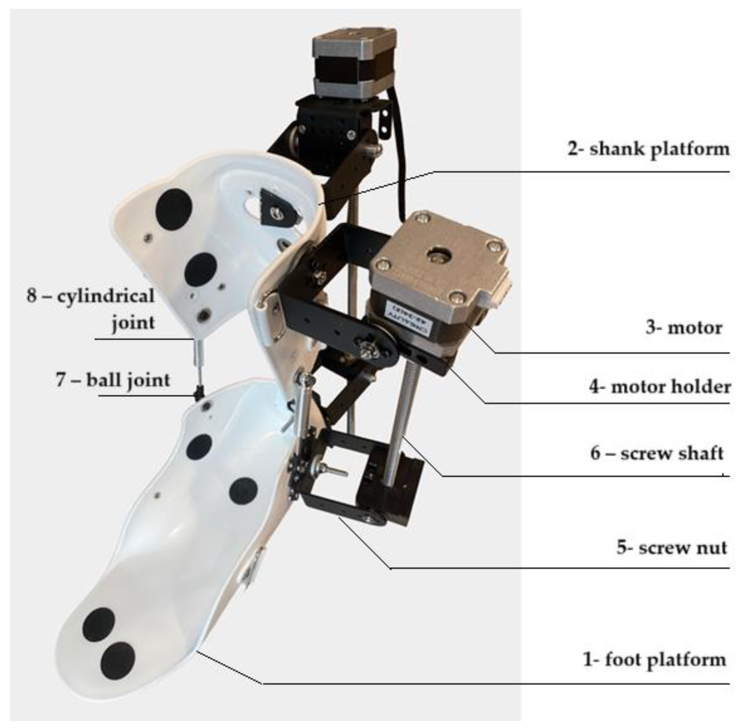
| 1 | foot platform | A support part of the exoskeleton that provides stability during movements. |
| 2 | shank platform | Fixes the user’s lower leg and connects it to other elements of the device, maintaining the correct position of the leg. |
| 3 | motor | The main drive element for controlling exoskeleton movements. |
| 4 | motor holder | Attaches the motor to the structure, ensuring its stable position and transmission of force to other parts of the exoskeleton. |
| 5 | screw nut | Works in tandem with the propeller shaft to convert rotary motion into linear motion. |
| 6 | screw shaft | Converts the rotary motion of the motor into linear motion for precise control in rehabilitation devices. The helical gearing provides smooth and controlled movements. |
| 7 | ball joint | Provides freedom of movement in several planes, allowing natural joint movements to be reproduced. |
| 8 | cylindrical joint | Enables the rotational movements that are necessary for the correct functioning of the mechanism. |
| Component | Commercial Name | Voltage | Mass | Max Force/Torque | Speed |
|---|---|---|---|---|---|
| Arduino board | Mega 2560 23 | 7–12 V | 37 g | — | — |
| Actuator | Mini Electric | 12 V | 150 g | 100 N | 20 mm/s |
| Servomotor | NEMA 17 | 4.8–7.2 V | 280 g | 150 N–cm | 461.5 deg/s |
| Driver | TB6600 | 4.75–12 B | 125 g | — | — |
| IMU | BMI16025 | 3–5 V | 2 g | — | — |
| EMG | Grove—EMG Detector | 3.3–5 B | 45 g | — | — |
Disclaimer/Publisher’s Note: The statements, opinions and data contained in all publications are solely those of the individual author(s) and contributor(s) and not of MDPI and/or the editor(s). MDPI and/or the editor(s) disclaim responsibility for any injury to people or property resulting from any ideas, methods, instructions or products referred to in the content. |
© 2025 by the authors. Licensee MDPI, Basel, Switzerland. This article is an open access article distributed under the terms and conditions of the Creative Commons Attribution (CC BY) license (https://creativecommons.org/licenses/by/4.0/).
Share and Cite
Sergazin, G.; Ozhiken, A.; Zhetenbayev, N.; Ozhikenov, K.; Tursunbayeva, G.; Nurgizat, Y.; Uzbekbayev, A.; Ayazbay, A.-A. Development of an Ankle Exoskeleton: Design, Modeling, and Testing. Sensors 2025, 25, 2020. https://doi.org/10.3390/s25072020
Sergazin G, Ozhiken A, Zhetenbayev N, Ozhikenov K, Tursunbayeva G, Nurgizat Y, Uzbekbayev A, Ayazbay A-A. Development of an Ankle Exoskeleton: Design, Modeling, and Testing. Sensors. 2025; 25(7):2020. https://doi.org/10.3390/s25072020
Chicago/Turabian StyleSergazin, Gani, Assylbek Ozhiken, Nursultan Zhetenbayev, Kassymbek Ozhikenov, Gulzhamal Tursunbayeva, Yerkebulan Nurgizat, Arman Uzbekbayev, and Abu-Alim Ayazbay. 2025. "Development of an Ankle Exoskeleton: Design, Modeling, and Testing" Sensors 25, no. 7: 2020. https://doi.org/10.3390/s25072020
APA StyleSergazin, G., Ozhiken, A., Zhetenbayev, N., Ozhikenov, K., Tursunbayeva, G., Nurgizat, Y., Uzbekbayev, A., & Ayazbay, A.-A. (2025). Development of an Ankle Exoskeleton: Design, Modeling, and Testing. Sensors, 25(7), 2020. https://doi.org/10.3390/s25072020