
A Hybrid RF/FSO Transmission System Based on a Shared Transmitter

Abstract
1. Introduction
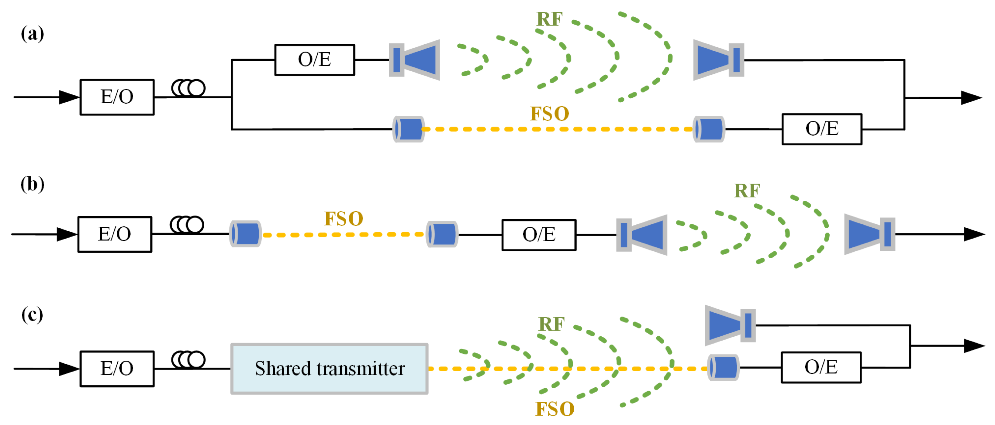
2. Principle
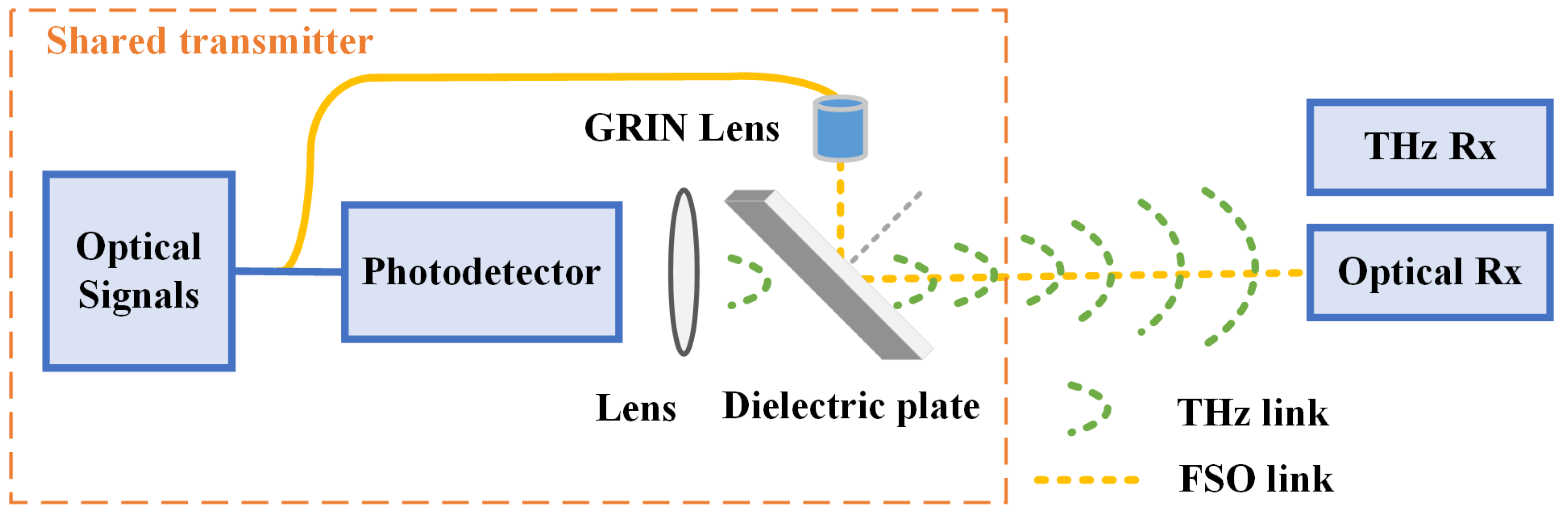
2.1. Design of Hybrid RF/FSO Structure
2.2. Channel Models
2.2.1. RF Link
2.2.2. FSO Link
2.2.3. Hybrid RF/FSO Link
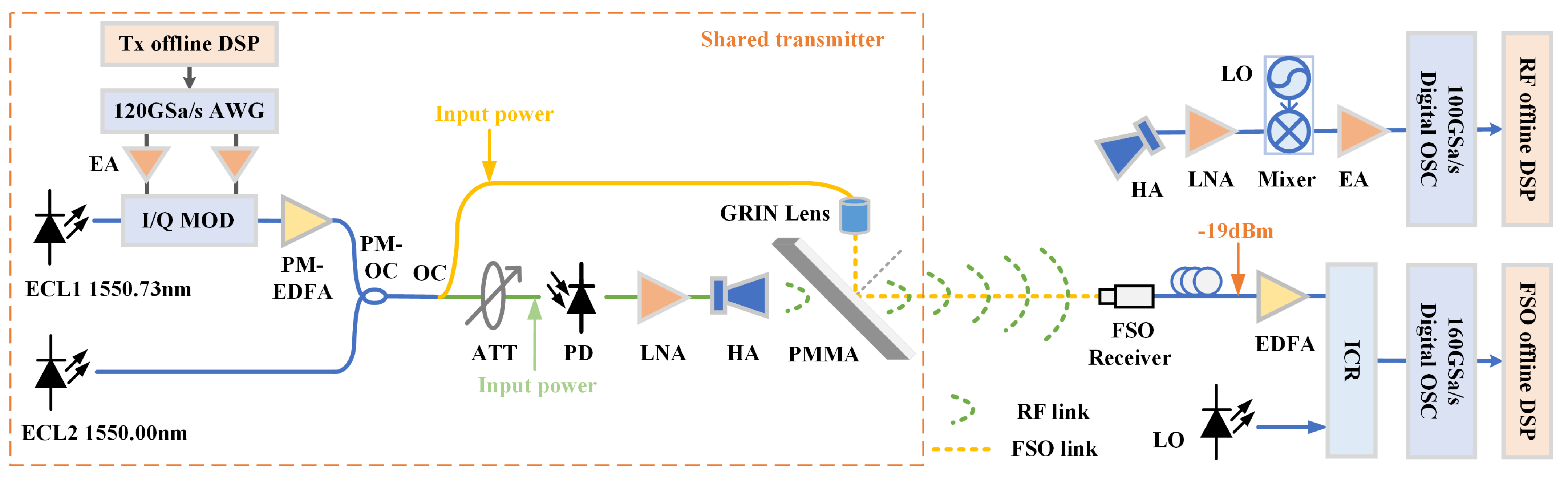
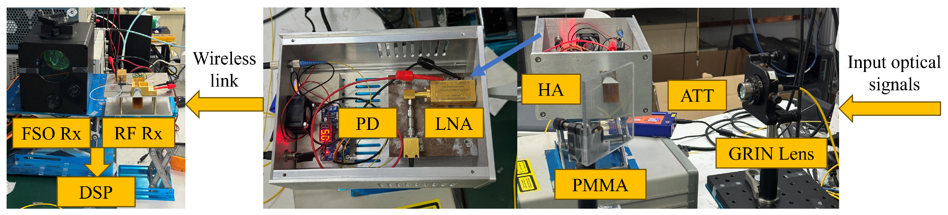
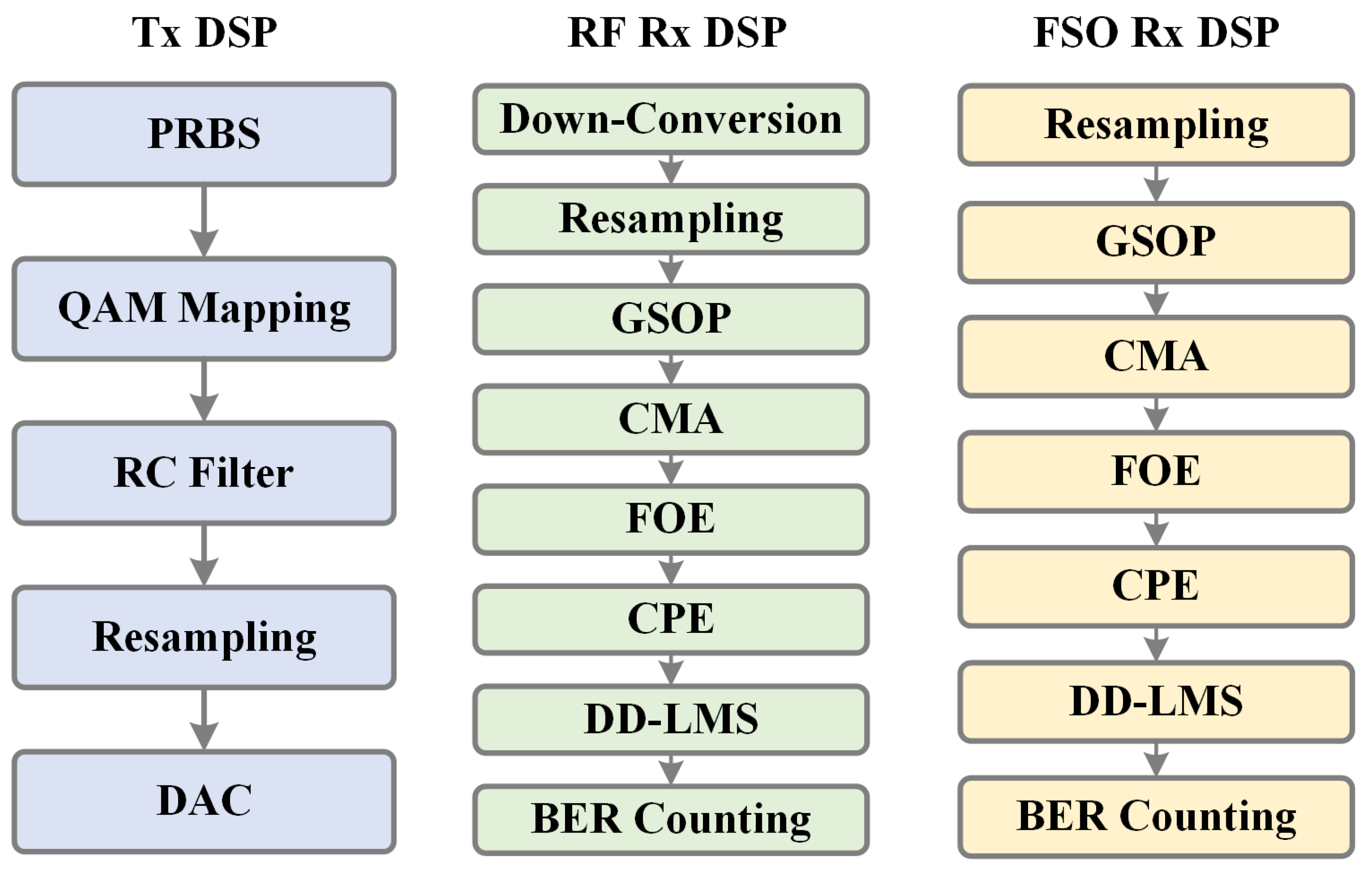
3. Experimental Setup
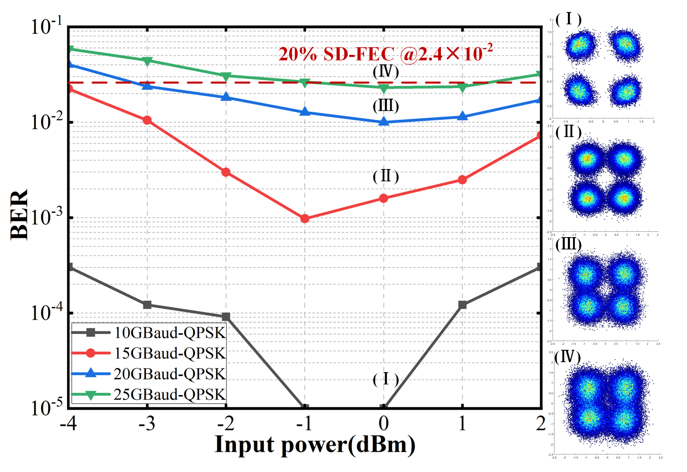
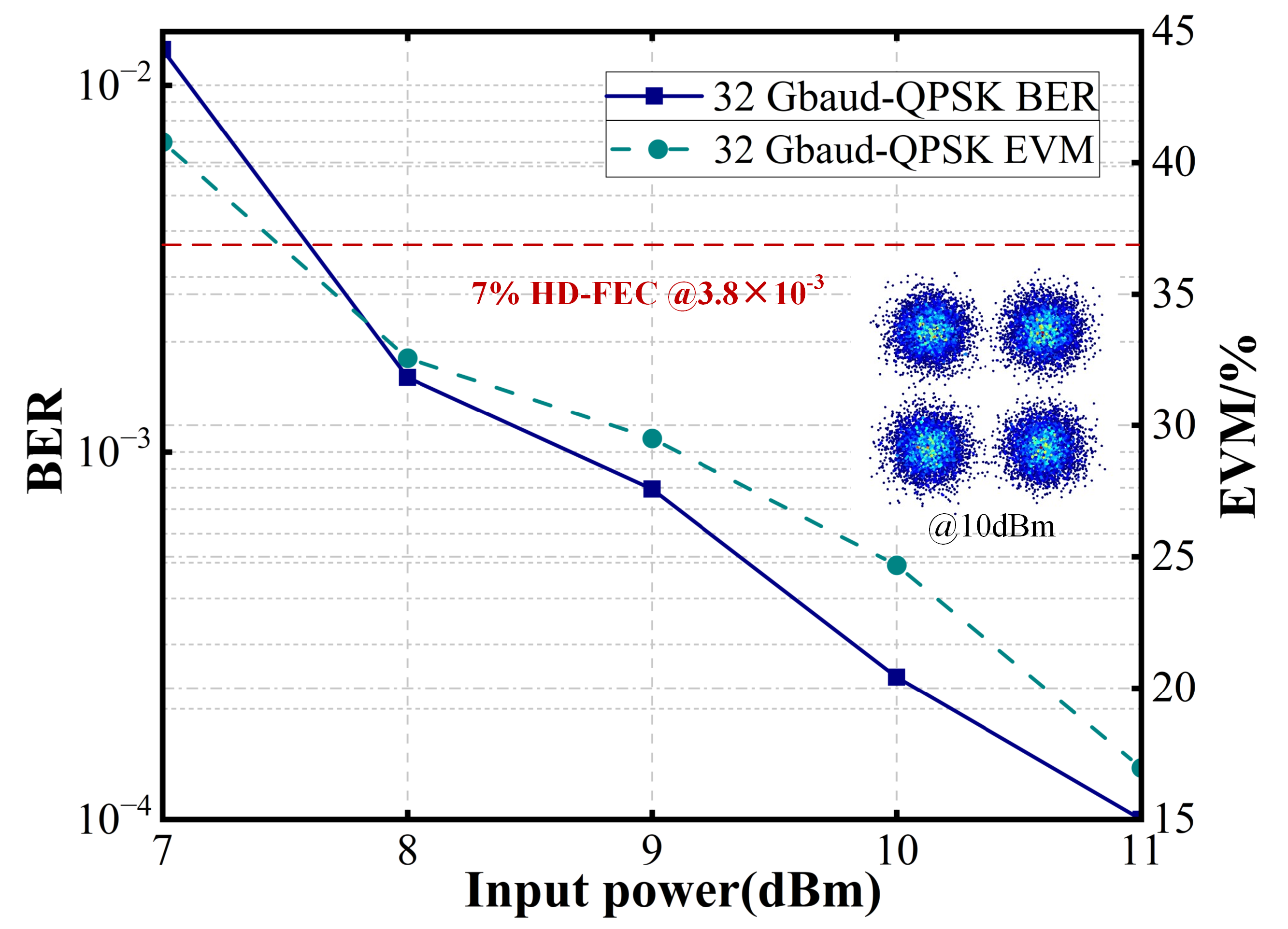
4. Results and Discussion
5. Conclusions
Author Contributions
Funding
Institutional Review Board Statement
Informed Consent Statement
Data Availability Statement
Conflicts of Interest
References
- Guo, X.; Tu, S.; Yan, D.; Wang, Y. On Security Performance of SWIPT Multi-User Jamming Based on Mixed RF/FSO Systems with Untrusted Relay. Sensors 2024, 24, 8203. [Google Scholar] [CrossRef]
- Wang, X.; Lv, K.; Pan, X.; Sheng, X.; Zhang, Q.; Xin, X. Impact of Super-Gaussian Distribution on Shaping Gain of Probabilistic Shaping 64QAM in Turbulence-Induced Coherent Free-Space Optical Communication Systems. In Proceedings of the 2024 Asia Communications and Photonics Conference (ACP) and International Conference on Information Photonics and Optical Communications (IPOC), Beijing, China, 2–5 November 2024; pp. 1–6. [Google Scholar]
- Wu, Y.; Li, G.; Kong, D. Performance analysis of relay-aided hybrid FSO/RF cooperation communication system over the generalized turbulence channels with pointing errors and nakagami-m fading channels. Sensors 2023, 23, 6191. [Google Scholar] [CrossRef] [PubMed]
- Khan, A.N.; Saeed, S.; Naeem, Y.; Zubair, M.; Massoud, Y.; Younis, U. Atmospheric turbulence and fog attenuation effects in controlled environment FSO communication links. IEEE Photonics Technol. Lett. 2022, 34, 1341–1344. [Google Scholar] [CrossRef]
- Matsuda, K.; Binkai, M.; Koshikawa, S.; Yoshida, T.; Sano, H.; Konishi, Y.; Suzuki, N. Demonstration of a real-time 14 Tb/s multi-aperture transmit single-aperture receive FSO system with class 1 eye-safe transmit intensity. J. Light. Technol. 2022, 40, 1494–1501. [Google Scholar] [CrossRef]
- Nadeem, F.; Kvicera, V.; Awan, M.S.; Leitgeb, E.; Muhammad, S.S.; Kandus, G. Weather effects on hybrid FSO/RF communication link. IEEE J. Sel. Areas Commun. 2009, 27, 1687–1697. [Google Scholar] [CrossRef]
- Yang, X.; Wei, Y.; Yu, J.; Zhao, X.; Wang, M.; Tan, J.; Li, W.; Zhao, F.; Bian, C.; Ma, H.; et al. Experimental demonstration of D-band signals wireless transmission over 30 km. Sci. China Technol. Sci. 2025, 68, 1280901. [Google Scholar]
- Yang, X.; Yu, J.; Zhao, X.; Wei, Y.; Li, W.; Shi, J.; Bian, C.; Zheng, T.; Zhao, F.; Zhou, W.; et al. 41.7-Gb/s D-band signals wireless delivery over 4.6 km distance based on photonics-aided technology. Opt. Laser Technol. 2024, 174, 110660. [Google Scholar]
- Wei, Y.; Yu, J.; Zhao, X.; Yang, X.; Wang, M.; Li, W.; Tian, P.; Han, Y.; Zhang, Q.; Tan, J.; et al. Demonstration of a photonics-aided 4600-m wireless transmission system in the sub-THz band. J. Lightwave Technol. 2024, 42, 8564–8576. [Google Scholar]
- Mohsan, S.A.H.; Khan, M.A.; Amjad, H. Hybrid FSO/RF Networks: A Review of Practical Constraints, Applications and Challenges. Opt. Switch Netw. 2023, 47, 100697. [Google Scholar]
- Hasabelnaby, M.A.; Selmy, H.A.; Dessouky, M.I. Joint optimal transceiver placement and resource allocation schemes for redirected cooperative hybrid FSO/mmW 5G fronthaul networks. J. Opt. Commun. Netw. 2018, 10, 975–990. [Google Scholar]
- Alfadhli, Y.; Peng, P.C.; Cho, H.; Liu, S.; Zhang, R.; Chen, Y.W.; Chang, G.K. Real-time FPGA demonstration of hybrid bi-directional MMW and FSO fronthaul architecture. In Proceedings of the 2019 Optical Fiber Communications Conference and Exhibition (OFC), San Diego, CA, USA, 3–7 March 2019; pp. 1–3. [Google Scholar]
- Guo, Z.; Gao, W.; Ye, H.; Wang, G. A location-aware resource optimization for maximizing throughput of emergency outdoor–indoor UAV communication with FSO/RF. Sensors 2023, 23, 2541. [Google Scholar] [CrossRef] [PubMed]
- Wu, Y.; Kong, D.; Wang, Q.; Li, G. Performance analysis of UAV-assisted hybrid FSO/RF communication systems under various weather conditions. Sensors 2023, 23, 7638. [Google Scholar] [CrossRef]
- Brandao, B.T.; Carvalho, P.P.; Fernandes, M.A.; Fernandes, G.M.; Guiomar, F.P.; Monteiro, P.P. Ultra-reliable 25G-400G+ wireless transmission over dense fog conditions enabled by hybrid FSO-mmWave. In Proceedings of the ECOC 2024; 50th European Conference on Optical Communication, Frankfurt, Germany, 22–26 September 2024; pp. 1251–1254. [Google Scholar]
- Dehnaw, A.M.; Manie, Y.C.; Du, L.-Y.; Yao, C.-K.; Jiang, J.-W.; Liu, B.-X.; Peng, P.-C. Integrated Sensor-Optics Communication System Using Bidirectional Fiber and FSO Channels and Hybrid Deep Learning Techniques. Sensors 2023, 23, 8434. [Google Scholar] [CrossRef] [PubMed]
- Meng, Z.; Liu, Y.; Gao, N.; Zhang, Z.; Wu, Z.; Gray, J. Radio frequency identification and sensing: Integration of wireless powering, sensing, and communication for IIoT innovations. IEEE Commun. Mag. 2021, 59, 38–44. [Google Scholar]
- Cui, L.; Zhang, Z.; Gao, N.; Meng, Z.; Li, Z. Radio Frequency Identification and Sensing Techniques and Their Applications-A Review of the State-of-the-Art. Sensors 2019, 19, 4012. [Google Scholar] [CrossRef]
- Hayle, S.T.; Manie, Y.C.; Yao, C.K.; Du, L.Y.; Yen, C.Y.; Fan, T.P.; Peng, P.C. Self-healing integration of fiber/FSO communication and sensor network for improving survivability. Opt. Fiber Technol. 2022, 74, 103090. [Google Scholar]
- Sun, Q.; Hu, Q.; Wu, Y.; Chen, X.; Zhang, J.; López-Benítez, M. Performance analysis of mixed FSO/RF system for satellite-terrestrial relay network. IEEE Trans. Veh. Technol. 2024, 73, 11378–11393. [Google Scholar]
- Li, C.Y.; Lu, H.H.; Chou, C.R.; Hsia, H.M.; Feng, C.Y.; Chen, Y.H.; Huang, Y.T.; Nainggolan, A. A flexible bidirectional fiber-FSO-5G wireless convergent system. J. Light. Technol. 2020, 39, 1296–1305. [Google Scholar]
- Lu, H.H.; Huang, X.H.; Li, C.Y.; Liu, C.X.; Lin, Y.Y.; Chen, Y.T.; Chang, P.S.; Ko, T. Bi-directional fiber-FSO-5G MMW/5G new radio sub-THz convergence. J. Light. Technol. 2021, 39, 7179–7190. [Google Scholar] [CrossRef]
- Nguyen, D.N.; Bohata, J.; Spacil, J.; Dousek, D.; Komanec, M.; Zvanovec, S.; Ghassemlooy, Z.; Ortega, B. M-QAM transmission over hybrid microwave photonic links at the K-band. Opt. Express 2019, 27, 33745–33756. [Google Scholar] [CrossRef]
- Sharma, S.; Madhukumar, A.S. Switching-based cooperative decode-and-forward relaying for hybrid FSO/RF networks. J. Opt. Commun. Netw. 2019, 11, 267–281. [Google Scholar] [CrossRef]
- Vargemidou, M.; Vagionas, C.; Kokkinis, A.; Michail, G.; Gatzianas, M.; Kalfas, G.; Mesodiakaki, A.; Wasko, W.; Abdulwahed, A.K.; Piscione, P.; et al. Real-time SDN controlled hybrid fiber wireless FSO/mmWave X-haul with zero-touch handover for terrestrial 6G networks. In Proceedings of the European Conference on Optical Communication, Basel, Switzerland, 18–22 September 2022. [Google Scholar]
- Song, S.; Liu, Y.; Wu, J.; Wu, T.; Zhao, L.; Guo, L. Demonstration of intelligent hybrid FSO/RF system based on enhanced GRU prediction and real-world meteorological dataset. J. Light. Technol. 2022, 40, 7048–7059. [Google Scholar] [CrossRef]
- Raza, W.; Abele, E.; O’Hara, J.; Sadr, B.; LoPresti, P.; Imran, A.; Choi, W.; Song, I.; Altunc, S.; Kegege, O.; et al. Toward a hybrid RF/optical lunar communication system (LunarComm). IEEE Netw. 2022, 36, 76–83. [Google Scholar] [CrossRef]
- Zhang, R.; Lu, F.; Xu, M.; Liu, S.; Peng, P.C.; Shen, S.; He, J.; Cho, H.J.; Zhou, Q.; Yao, S.; et al. An ultra-reliable MMW/FSO A-RoF system based on coordinated mapping and combining technique for 5G and beyond mobile fronthaul. J. Light. Technol. 2018, 36, 4952–4959. [Google Scholar] [CrossRef]
- Usman, M.; Yang, H.C.; Alouini, M.S. Practical switching-based hybrid FSO/RF transmission and its performance analysis. IEEE Photonics J. 2014, 6, 7902713. [Google Scholar] [CrossRef]
- Wang, K.; Yu, J.; Wei, Y.; Chi, N.; Li, X.; Xiao, J.; Hu, F.; Zhao, M.; Zhu, B.; Zhang, J.; et al. Delivery of 1.196-Tb/s signal over 800 M based on RF/FSO convergence. In Proceedings of the 45th European Conference on Optical Communication (ECOC 2019), Dublin, Ireland, 22–26 September 2019. [Google Scholar]
- Kyriazi, E.; Toumasis, P.; Brestas, G.; Ntanos, A.; Stathis, A.; Poulopoulos, G.; Giannoulis, G.; Diakakis, D.; Mesogiti, I.; Theodoropoulou, E.; et al. A demonstration of hybrid fiber/FSO/millimeter-wave transmission for 6G robust backhaul. In Proceedings of the ECOC 2024; 50th European Conference on Optical Communication, Frankfurt, Germany, 22–26 September 2024; pp. 1130–1133. [Google Scholar]
- Shao, J.; Liu, Y.; Du, X.; Xie, T. Adaptive Modulation Scheme for Soft-Switching Hybrid FSO/RF Links Based on Machine Learning. Photonics 2024, 11, 404. [Google Scholar] [CrossRef]
- Palitharathna, K.W.; Suraweera, H.A.; Godaliyadda, R.I.; Herath, V.R.; Ding, Z. Neural Network-Based Blockage Prediction and Optimization in Lightwave Power Transfer-Enabled Hybrid VLC Systems. IEEE Internet Things J. 2023, 11, 5237–5248. [Google Scholar] [CrossRef]
- Abadi, M.M.; Ghassemlooy, Z.; Smith, D.; Ng, W.P. A report on H-FSO/RF antenna measurement for outdoor applications. In Proceedings of the 2013 2nd International Workshop on Optical Wireless Communications (IWOW), Newcastle Upon Tyne, UK, 21 October 2013; pp. 118–122. [Google Scholar]
- Abadi, M.M.; Ghassemlooy, Z.; Zvanovec, S.; Smith, D.; Bhatnagar, M.R.; Wu, Y. Dual purpose antenna for hybrid free space optics/RF communication systems. J. Light. Technol. 2016, 34, 3432–3439. [Google Scholar] [CrossRef]
- Liang, J.; Chen, M.; Ke, X. Performance analysis of hybrid FSO/RF-THz relay communication system. IEEE Photonics J. 2024, 73, 1–10. [Google Scholar] [CrossRef]
- Singya, P.K.; Makki, B.; D’Errico, A.; Alouini, M.S. Hybrid FSO/THz-based backhaul network for mmWave terrestrial communication. IEEE Trans. Wirel. Commun. 2022, 22, 4342–4359. [Google Scholar] [CrossRef]


| Modem Format | RF Link Transmission Rate (bit/s) | FSO Link Transmission Rate (bit/s) |
|---|---|---|
| QPSK | 50 G | 200 G |
| 16QAM | Invalidate | 128 G |
Disclaimer/Publisher’s Note: The statements, opinions and data contained in all publications are solely those of the individual author(s) and contributor(s) and not of MDPI and/or the editor(s). MDPI and/or the editor(s) disclaim responsibility for any injury to people or property resulting from any ideas, methods, instructions or products referred to in the content. |
© 2025 by the authors. Licensee MDPI, Basel, Switzerland. This article is an open access article distributed under the terms and conditions of the Creative Commons Attribution (CC BY) license (https://creativecommons.org/licenses/by/4.0/).
Share and Cite
Zhang, Q.; Yu, J.; Long, J.; Wang, C.; Chen, J.; Lu, X. A Hybrid RF/FSO Transmission System Based on a Shared Transmitter. Sensors 2025, 25, 2021. https://doi.org/10.3390/s25072021
Zhang Q, Yu J, Long J, Wang C, Chen J, Lu X. A Hybrid RF/FSO Transmission System Based on a Shared Transmitter. Sensors. 2025; 25(7):2021. https://doi.org/10.3390/s25072021
Chicago/Turabian StyleZhang, Qinyi, Jianjun Yu, Jianyu Long, Chen Wang, Jiali Chen, and Xin Lu. 2025. "A Hybrid RF/FSO Transmission System Based on a Shared Transmitter" Sensors 25, no. 7: 2021. https://doi.org/10.3390/s25072021
APA StyleZhang, Q., Yu, J., Long, J., Wang, C., Chen, J., & Lu, X. (2025). A Hybrid RF/FSO Transmission System Based on a Shared Transmitter. Sensors, 25(7), 2021. https://doi.org/10.3390/s25072021