


Advancements in Surface Acoustic Wave Gyroscope Technology in 2015–2024
 , ,
, ,
Abstract
1. Introduction
- Theoretical works that contain only theory, no simulation (except numerical evaluation of obtained expressions) and no experiments.
- Works dedicated mainly to simulation and modeling. These papers may contain some novel construction ideas and corresponding theoretical findings, but do not have any experimental evaluations.
- Works describing the optimization of well-known design principles. These papers may contain a theoretical part, numerical modeling, and experimental results, but are primarily dedicated to improving design concepts that do not differ much from well-known examples.
- An overview of papers that describe totally new ideas, for example, incorporating other physical principles, and are illustrations of “outside-the-box thinking” is completed in Section 6.
- The final section that precedes the Discussion Section is dedicated to the papers describing novel ideas in the SAWG fabrication process.
2. Basic Operation Principles
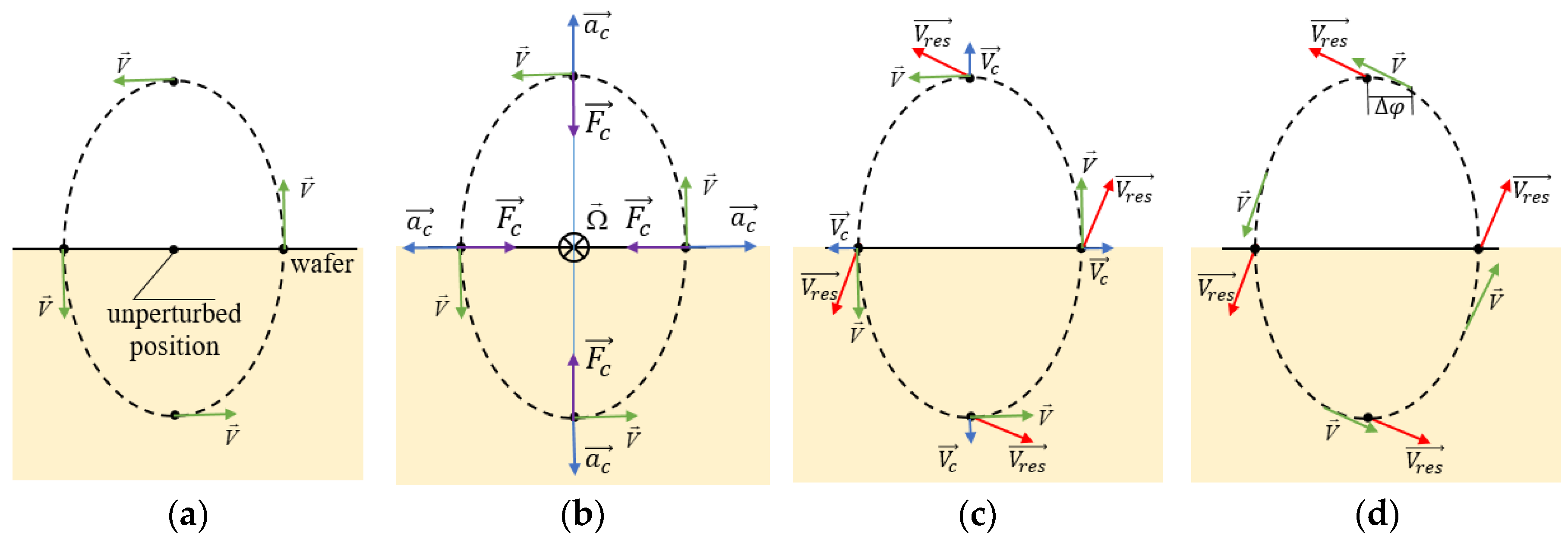
2.1. The Coriolis Effect in Running SAWs
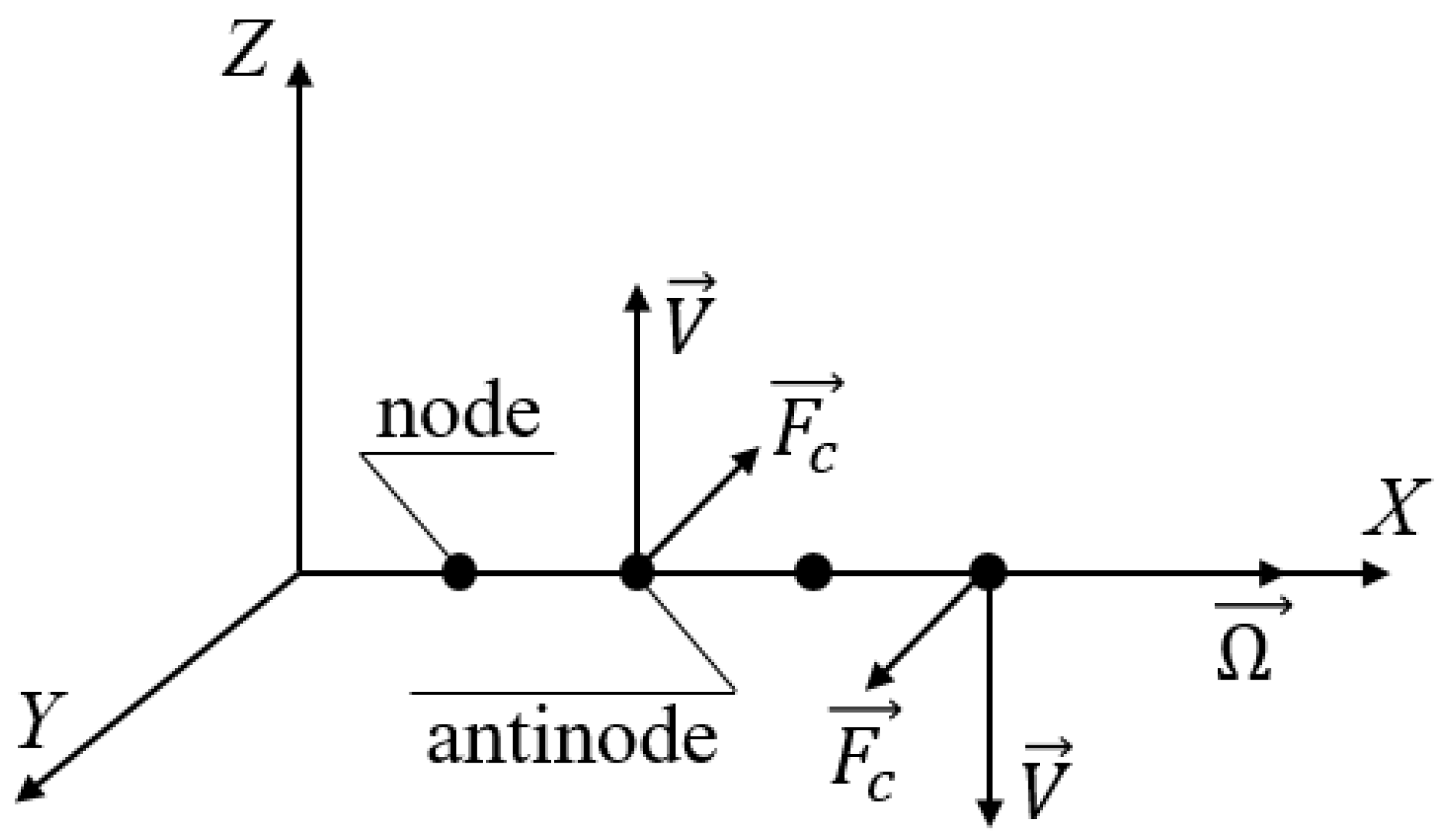
2.2. The Coriolis Effect in Standing SAWs
3. Theoretical Works
- Long waves are more sensitive to rotation than short ones;
- A more evident change in frequency occurs when the free surface is electrically shorted.
- The wave attenuation also decreases with higher rotation rates.
- The biasing electric field, along with the steady-state carrier concentration, has a strong influence on the wave velocity and attenuation; these dependencies have extremum points and might be used as an instrument for SAWG parameters optimization.
4. Simulation and Modeling
- In a double-layer substrate structure, the greater the difference in reflection coefficients between the upper and lower-layer materials, the higher the sensor sensitivity is. From this point of view, the diamond used as the lower layer shows the best performance.
- Reducing the piezoelectric film thickness enhances the sensor sensitivity as well.
- The optimal size of the metallic dot (the inertial mass) should be calculated separately for each substrate structure.
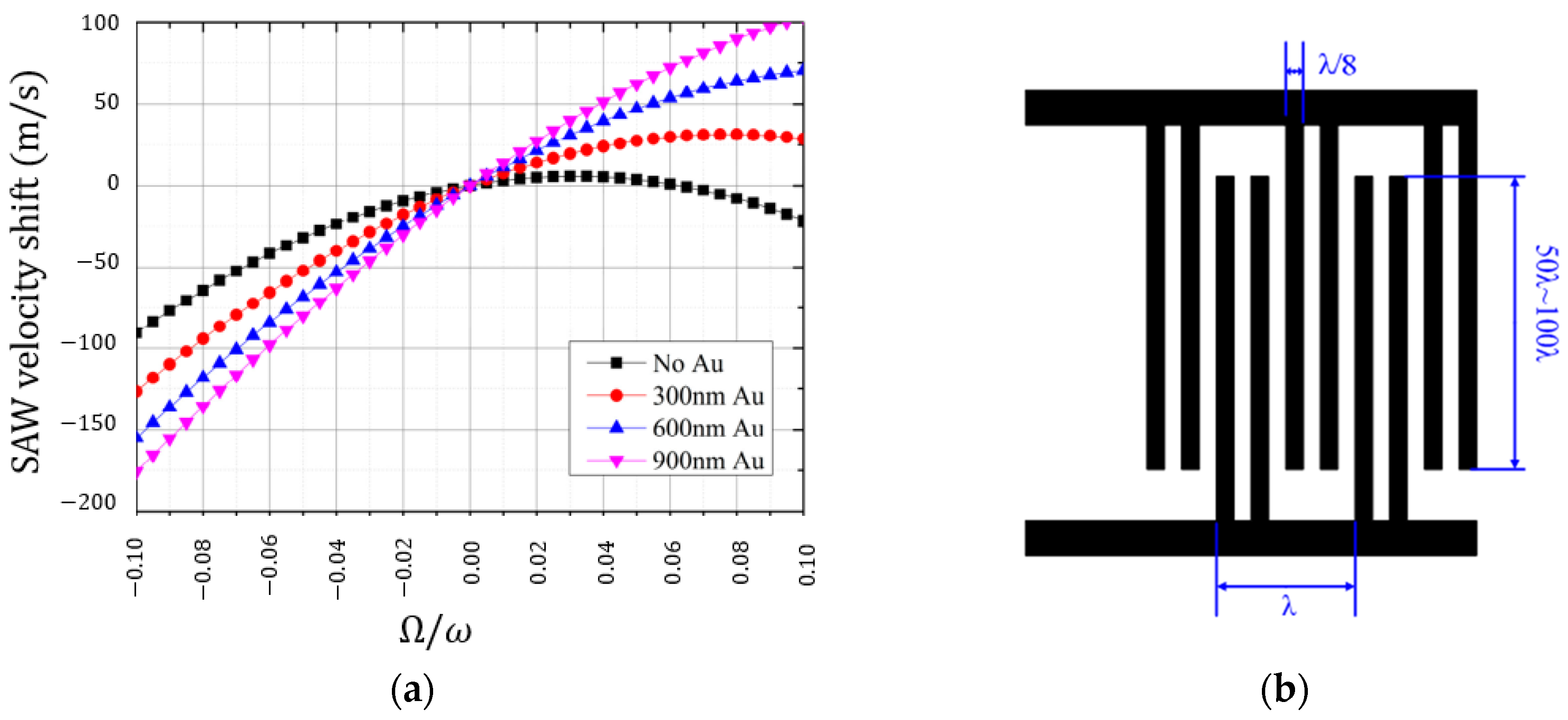
5. Optimization
- In terms of the wafer material, LiNbO3 shows better performance than LiTaO3, probably because of higher K2.
- Inertial masses made of gold show higher sensitivity than those made of copper, and devices with inertial masses are definitely more sensitive than those without inertial masses at all.
- Thicker metallic dots also provide better sensitivity.
- Lower operation frequency is accompanied by better sensitivity.
6. New Physical Principles
6.1. Co-Existing SAW and BAW
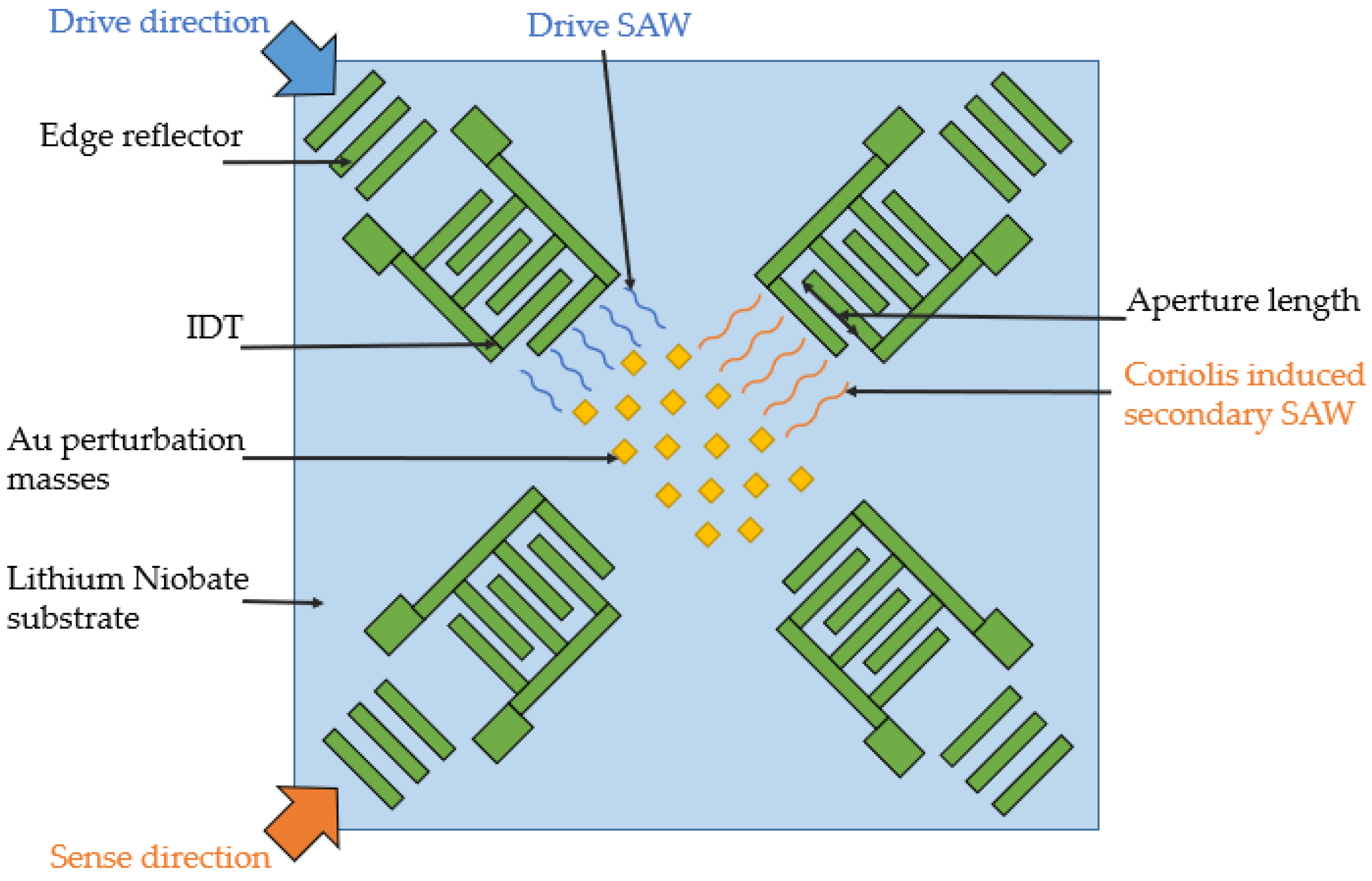
- While the main idea is to create a dual-axis sensor, it is obvious that the sensitivity for both axes would be different. This is due to the fact that in the X-direction there are running SAWs induced by the original bulk wave together with waves induced by the Coriolis force, while in the Y-direction there are only waves induced by the Coriolis force.
- The signal processing scheme is not clear from the description, but should be rather complicated.
- The signal is expected to be low since a lot of energy flows away from the system as there are no reflectors behind the IDTs.
- The fabrication process of the device would be very challenging since it requires strict alignment of all its parts. In addition, the complicated shape of the sensing element increases the sensor size, and, probably, reduces its shock resistance.
6.2. Acousto-Optical Designs
6.3. Exotics
7. The Fabrication Process
8. Discussion
Author Contributions
Funding
Institutional Review Board Statement
Informed Consent Statement
Data Availability Statement
Conflicts of Interest
References
- Oh, H.; Lee, K.J.; Lee, K.; Yang, S.S. Gyroscopes based on surface acoustic waves. Micro Nano Syst. Lett. 2015, 3, 1. [Google Scholar] [CrossRef]
- Lao, B.Y. Gyroscopic effect in surface acoustic waves. In Proceedings of the IEEE Ultrasonics Symposium, Boston, MA, USA, 5–7 November 1980; pp. 687–691. [Google Scholar] [CrossRef]
- Lee, S.W.; Rhim, J.W.; Park, S.W.; Yang, S.S. A micro rate gyroscope based on the SAW gyroscopic effect. J. Micromech. Microeng. 2007, 17, 2272–2279. [Google Scholar] [CrossRef]
- Kurosawa, M.; Fukuda, Y.; Takasaki, M.; Highuchi, T. A surface acoustic wave gyro sensors. Sens. Actuators A Phys. 1997, 66, 33–39. [Google Scholar] [CrossRef]
- Zhou, Y.H.; Jiang, Q. Effects of Coriolis force and centrifugal force on acoustic waves propagating along the surface of a piezoelectric half-space. Z. Angew. Math. Phys. ZAMP 2001, 52, 950–965. [Google Scholar] [CrossRef]
- Wang, W.; Xu, F.; He, S.; Li, S.; Lee, K. A new micro-rate sensor based on shear horizontal surface acoustic wave gyroscopic effect. Jpn. J. Appl. Phys. 2010, 49, 096602. [Google Scholar] [CrossRef]
- Sarapuloff, S.A.; Skrypkovsky, G.A.; Rhim, J. Inertial effects in surface and bulk elastic waves and possibility of their use in high-G solid-state micro gyroscopes. In Proceedings of the 12th Saint Petersburg International Conference on Integrated Navigation Systems, ICINS, Saint Petersburg, Russia, 23–25 May 2005; pp. 355–361. [Google Scholar]
- Hu, S.-M.; Hu, Y.-F.; Cao, X.-S.; Tian, S.-M. Gyro effect on surface acoustic wave propagation in a piezoelectric layered structure. In Proceedings of the 2019 14th Symposium on Piezoelectricity, Acoustic Waves and Device Applications (SPAWDA), IEEE, Shijiazhuang, China, 2–4 November 2019; pp. 1–5. [Google Scholar] [CrossRef]
- Yuan, X.; Gao, Z.; Hao, C.; Jiang, Q. Effects of rotation and electric bias in the semi-infinite piezoelectric medium on Rayleigh wave velocity. ZAMM-J. Appl. Math. Mech. Z. Angew. Math. Mech. 2023, 103, e202200440. [Google Scholar] [CrossRef]
- Yang, L.; Zappino, E.; Carrera, E.; Du, J. Rotation effects on propagation of shear horizontal surface waves in piezomagnetic-piezoelectric semiconductor layered structures. Appl. Math. Model. 2024, 129, 494–508. [Google Scholar] [CrossRef]
- Sun, X.; Liu, W.; Shao, X.; Zhou, S.; Wang, W.; Lin, D. Surface acoustic wave gyroscopic effect in an interdigital transducer. Sensors 2018, 19, 106. [Google Scholar] [CrossRef]
- Ma, R.; Liu, W.; Sun, X.; Zhou, S.; Lin, D. FEM simulation of a high-Performance 128 Y–X LiNbO3/SiO2/Si functional substrate for surface acoustic wave gyroscopes. Micromachines 2022, 13, 202. [Google Scholar] [CrossRef]
- Chen, H.; Lu, M.; Meng, L.; Wang, W.; Shao, X. Finite Element Analysis of the Distribution Parameters of a Metal Dot Array in a SAW Gyroscope. Appl. Sci. 2022, 12, 8062. [Google Scholar] [CrossRef]
- Wang, W.; Shao, X.; Liu, X.; Liu, J.; He, S. Enhanced Sensitivity of Surface Acoustic Wave-Based Rate Sensors Incorporating Metallic Dot Arrays. Sensors 2014, 14, 3908–3920. [Google Scholar] [CrossRef]
- Chen, H.; Meng, L.; Lu, M.; Song, Z.; Wang, W.; Shao, X. Research on the SAW Gyroscopic Effect in a Double-Layer Substrate Structure Incorporating Non-Piezoelectric Materials. Micromachines 2023, 14, 1834. [Google Scholar] [CrossRef] [PubMed]
- Xu, F.; Wang, W.; Shao, X.; Liu, X.; Liang, Y. Optimization of surface acoustic wave-based rate sensors. Sensors 2015, 15, 25761–25773. [Google Scholar] [CrossRef] [PubMed]
- Lukyanov, D.P.; Kukaev, A.S.; Shevchenko, S.Y. Design optimization of a microgyrocsope on standing surface acoustic waves. In Proceedings of the 2017 24th Saint Petersburg International Conference on Integrated Navigation Systems (ICINS), IEEE, Saint Petersburg, Russia, 29–31 May 2017; pp. 1–3. [Google Scholar] [CrossRef]
- Mahmoud, A.; Mahmoud, M.; Mukherjee, T.; Piazza, G. Investigating the impact of resonant cavity design on surface acoustic wave gyroscope. In Proceedings of the 2018 IEEE International Symposium on Inertial Sensors and Systems (INERTIAL), Lake Como, Italy, 26–29 March 2018; pp. 1–4. [Google Scholar] [CrossRef]
- Mahmoud, A.; Mukherjee, T.; Piazza, G. Novel Acoustic Gratings with High Reflection Constant for Surface Acoustic Wave Gyroscopes. In Proceedings of the 2018 IEEE International Ultrasonics Symposium (IUS), Kobe, Japan, 22–25 October 2018; pp. 206–212. [Google Scholar] [CrossRef]
- Mahmoud, A.; Mukherjee, T.; Piazza, G. A study of quality factor in SAW resonators for SAW gyroscope applications. In Proceedings of the 2020 Joint Conference of the IEEE International Frequency Control Symposium and International Symposium on Applications of Ferroelectrics (IFCS-ISAF), Keystone, CO, USA, 19–23 July 2020; pp. 1–3. [Google Scholar] [CrossRef]
- Mahmoud, A.; Mukherjee, T.; Piazza, G. Investigating long-term stability of wide bandwidth surface acoustic waves gyroscopes using a monolithically integrated micro-oven. In Proceedings of the 2020 IEEE 33rd International Conference on Micro Electro Mechanical Systems (MEMS), Vancouver, BC, Canada, 18–22 January 2020; pp. 252–254. [Google Scholar] [CrossRef]
- Kurosawa, M.; Fukuda, Y.; Takasaki, M.; Highuchi, T. A surface acoustic wave gyro sensors. In Proceedings of the International Solid State Sensors and Actuators Conference (Transducers ’97), Chicago, IL, USA, 19 June 1997; Volume 2, pp. 863–866; [Google Scholar] [CrossRef]
- Tian, L.; Zhao, H.; Shen, Q.; Chang, H. A toroidal SAW gyroscope with focused IDTs for sensitivity enhancement. Microsyst. Nanoeng. 2024, 10, 37. [Google Scholar] [CrossRef]
- Sizov, V.P.; Pogorelov, V.A.; Vakhtin, Y.V. Rotation effect on parameters of elastic waves propagating in substrate of SAW-based solid-state gyros. Gyroscopy Navig. 2016, 7, 159–167. [Google Scholar] [CrossRef]
- Davaji, B.; Visarute, P.; Kulkarni, S.; Lal, A. Towards a surface and bulk excited SAW gyroscope. In Proceedings of the 2017 IEEE International Ultrasonics Symposium (IUS), Washington, DC, USA, 6–9 September 2017; pp. 1–4. [Google Scholar] [CrossRef]
- Visarute, P.; Davaji, B.; Lal, A. Coexisting surface and bulk gyroscopic effects. In Proceedings of the 2018 IEEE International Ultrasonics Symposium (IUS), Kobe, Japan, 22–25 October 2018; pp. 1–4. [Google Scholar] [CrossRef]
- Visarute, P.; Davaji, B.; Lal, A. High-overtone bulk diffraction wave gyroscope. In Proceedings of the 2019 IEEE 32nd International Conference on Micro Electro Mechanical Systems (MEMS), Seoul, Korea, 27–31 January 2019; pp. 202–205. [Google Scholar] [CrossRef]
- Shuxiang, L.; Chen, S.; Zhao, Y. MOEMS gyroscope based on acoustooptic mode coupling. In Proceedings of the Asia Communications and Photonics Conference and Exhibition, Optica Publishing Group, Shanghai, China, 8–12 December 2010; pp. 292–293. [Google Scholar] [CrossRef]
- Shuxiang, L.; Shufen, C.; Honglang, L.; Lei, F.; Zhengfeng, Z.; Yanbin, M. Detecting surface acoustic wave gyroscopic signal by acousto-optic coupling. Appl. Phys. Lett. 2011, 99, 251116. [Google Scholar] [CrossRef]
- Mahmoud, M.; Mahmoud, A.; Cai, L.; Khan, M.; Mukherjee, T.; Bain, J.; Piazza, G. Novel on chip rotation detection based on the acousto-optic effect in surface acoustic wave gyroscopes. Opt. Express 2018, 19, 25060–25075. [Google Scholar] [CrossRef]
- Mahmoud, A.; Cai, L.; Bain, J.; Mukherjee, T.; Piazza, G. Acousto-optic gyroscope with improved sensitivity and 100 second stability in a small form factor. In Proceedings of the 2019 IEEE International Symposium on Inertial Sensors and Systems (INERTIAL), Naples, FL, USA, 1–5 April 2019; pp. 1–4. [Google Scholar] [CrossRef]
- Tian, L.; Qiang, S.; Honglong, C. A novel progressive wave gyroscope based on acousto-optic effects. Microsyst. Nanoeng. 2022, 8, 95. [Google Scholar] [CrossRef]
- Biryukov, S.V.; Martin, G.; Weihnacht, M. Ring waveguide resonator on surface acoustic waves. Appl. Phys. Lett. 2007, 90, 17. [Google Scholar] [CrossRef]
- Herasymenko, D.O.; Zhovnir, M.F.; Pysarenko, L.D. Angular Velocity Transducer with Ring Resonator of Surface Acoustic Waves. In Proceedings of the 2018 IEEE 38th International Conference on Electronics and Nanotechnology (ELNANO), Kyiv, Ukraine, 24–26 April 2018; pp. 734–738. [Google Scholar] [CrossRef]
- Zhu, Y.; Shibei, X.; Fangfang, J.; Haidong, Y. Quantum gyroscopes based on double-mode surface-acoustic-wave cavities. Phys. Rev. Appl. 2024, 22, 014061. [Google Scholar] [CrossRef]
- Fei, G.; Zhao, L.; Zhang, Y. Design and Optimization of a Novel SAW Gyroscope Structure Based on Amplitude Modulation with 1-D Phononic Crystals. Micromachines 2021, 12, 1485. [Google Scholar] [CrossRef] [PubMed]
- Kulkarni, S.S. Gauge Factor of Graphene Piezoresistor for Surface Acoustic Wave Gyroscope Instrumentation. Master’s Thesis, Cornell University, Ithaca, NY, USA, 30 August 2018. [Google Scholar]
- Wang, W.; Wang, W.; Liu, J.; Liu, M.; Yang, S. Wireless and passive gyroscope based on surface acoustic wave gyroscopic effect. Appl. Phys. Express 2011, 4, 086601. [Google Scholar] [CrossRef]
- Lal, A.; Serhan, M.A. Surface Acoustic Wave (SAW)-Based Inertial Sensor, Methods, and Applications. U.S. Patent No. 11249105, 15 February 2022. [Google Scholar]
- Kukaev, A.S.; Safronov, D.V. Development of fast prototyping laser technique for production of surface acoustic wave gyroscopes. J. Phys. Conf. Ser. 2020, 1536, 012014. [Google Scholar] [CrossRef]
- Safronov, D.V.; Kukaev, A.S.; Shubin, G.M.; Gorelaya, A.V.; Venediktov, V.Y. UV laser formation of complex topologies for sensitive elements of navigation sensors based on surface acoustic waves. Opt. Laser Technol. 2024, 169, 110000. [Google Scholar] [CrossRef]


| Source | Main Idea | SAW Type | Design Stage | Temperature Sensitivity | Bias Instability, °/s | Scale Factor | Comments |
|---|---|---|---|---|---|---|---|
| [18,19,20,21] | Orthogonal 45° rotated design with ovenization | Standing | Experimental setup | Ovenization mechanism | 0.007 | 0.959 µV/(°/s) | Papers represent the evolution of the same principle |
| [23] | Orthogonal design with focused IDTs | Standing | Experimental setup | High sensitivity | 0.77 | 1.51 µV/(°/s) | - |
| [26,27] | Use of bulk wave mode | Standing | Experimental setup | Temp. compensation by the bulk mode | 0.0022 | 191 µV/(°/s) | Temp. compensation algorithm is not explained |
| [31] | AOG: Mach-Zehnder interferometer affected by induced SAW | Standing | Experimental setup | Not discussed | 2.8 × 10⁻⁴ | 0.275 µV/(°/s) | - |
| [32] | AOG: optical waveguides affected by running SAW | Running | Simulation | Differential scheme | - | 1.8647 (mW/m²)/ (rad/s) | Working principle is unclear |
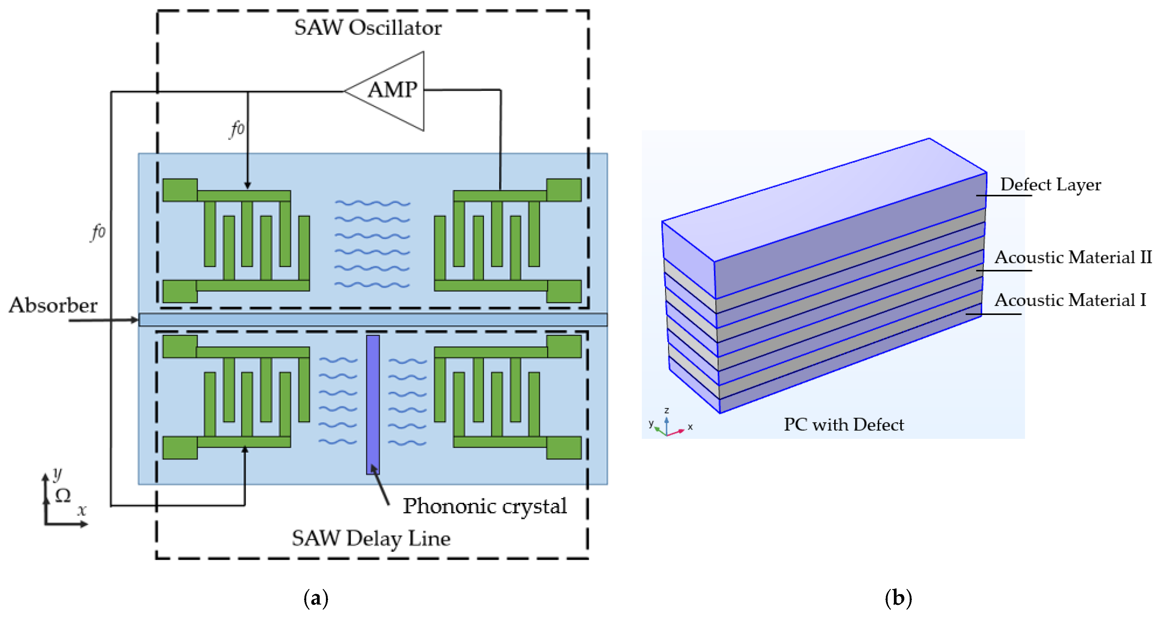
| [36] | Use of phononic crystals | Running | Simulation | Not discussed | - | 23.1 mV/(rad/s) | SF is only for −8…8 rad/s |
Disclaimer/Publisher’s Note: The statements, opinions and data contained in all publications are solely those of the individual author(s) and contributor(s) and not of MDPI and/or the editor(s). MDPI and/or the editor(s) disclaim responsibility for any injury to people or property resulting from any ideas, methods, instructions or products referred to in the content. |
© 2025 by the authors. Licensee MDPI, Basel, Switzerland. This article is an open access article distributed under the terms and conditions of the Creative Commons Attribution (CC BY) license (https://creativecommons.org/licenses/by/4.0/).
Share and Cite
Kukaev, A.; Shalymov, E.; Shevchenko, S.; Sorvina, M.; Venediktov, V. Advancements in Surface Acoustic Wave Gyroscope Technology in 2015–2024. Sensors 2025, 25, 877. https://doi.org/10.3390/s25030877
Kukaev A, Shalymov E, Shevchenko S, Sorvina M, Venediktov V. Advancements in Surface Acoustic Wave Gyroscope Technology in 2015–2024. Sensors. 2025; 25(3):877. https://doi.org/10.3390/s25030877
Chicago/Turabian StyleKukaev, Alexander, Egor Shalymov, Sergey Shevchenko, Maria Sorvina, and Vladimir Venediktov. 2025. "Advancements in Surface Acoustic Wave Gyroscope Technology in 2015–2024" Sensors 25, no. 3: 877. https://doi.org/10.3390/s25030877
APA StyleKukaev, A., Shalymov, E., Shevchenko, S., Sorvina, M., & Venediktov, V. (2025). Advancements in Surface Acoustic Wave Gyroscope Technology in 2015–2024. Sensors, 25(3), 877. https://doi.org/10.3390/s25030877