
Adaptive Exoskeleton Device for Stress Reduction in the Ankle Joint Orthosis


Abstract
1. Introduction
- Identification of the cause-and-effect relationships between joint movement, human muscular activity, and the motion of exoskeletal system components.
- Analysis of the impact of individual operator characteristics on the control and performance of the exoskeleton device.
- Enhancement of fatigue resistance and structural durability in the proposed exoskeleton model.
- Comparative assessment of the patient’s condition before and after using the proposed exoskeleton model, to determine the most suitable design, based on the following:
- a: an experimental test;
- b: the opinion of the patient’s attending physician.
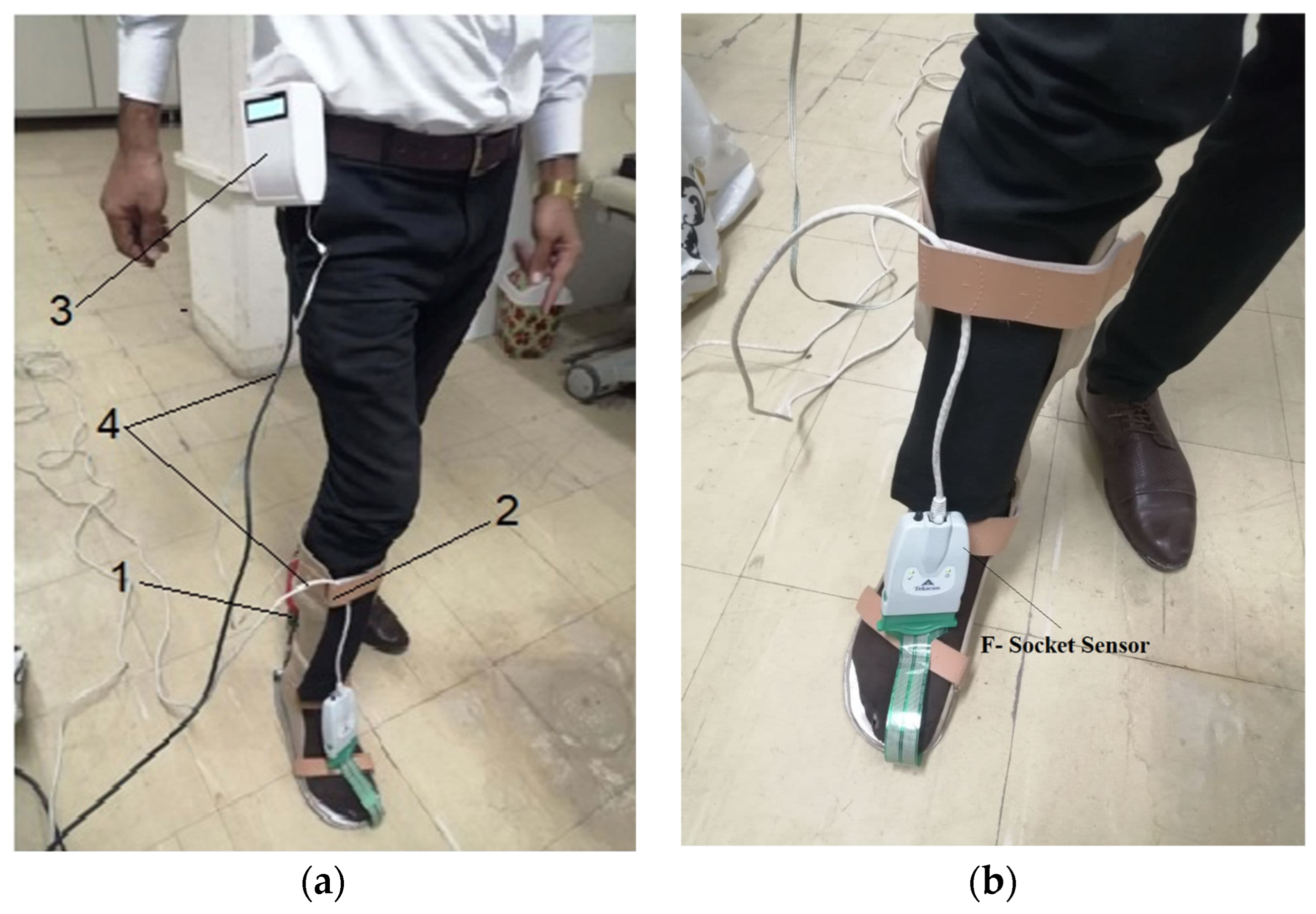
- Development of a cost-effective and highly accurate force sensor: This study introduces a novel force sensor that is significantly more affordable than existing models, such as the socket-type F sensor, while offering comparable or superior accuracy.
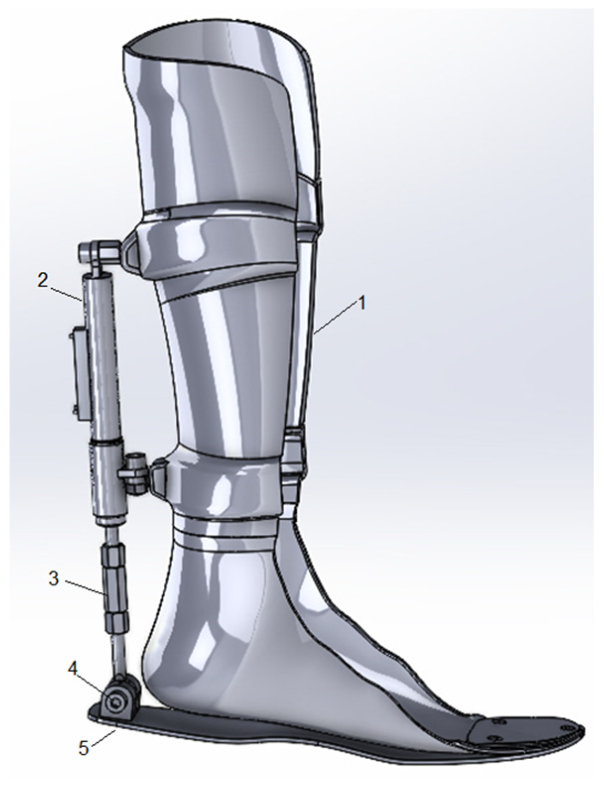
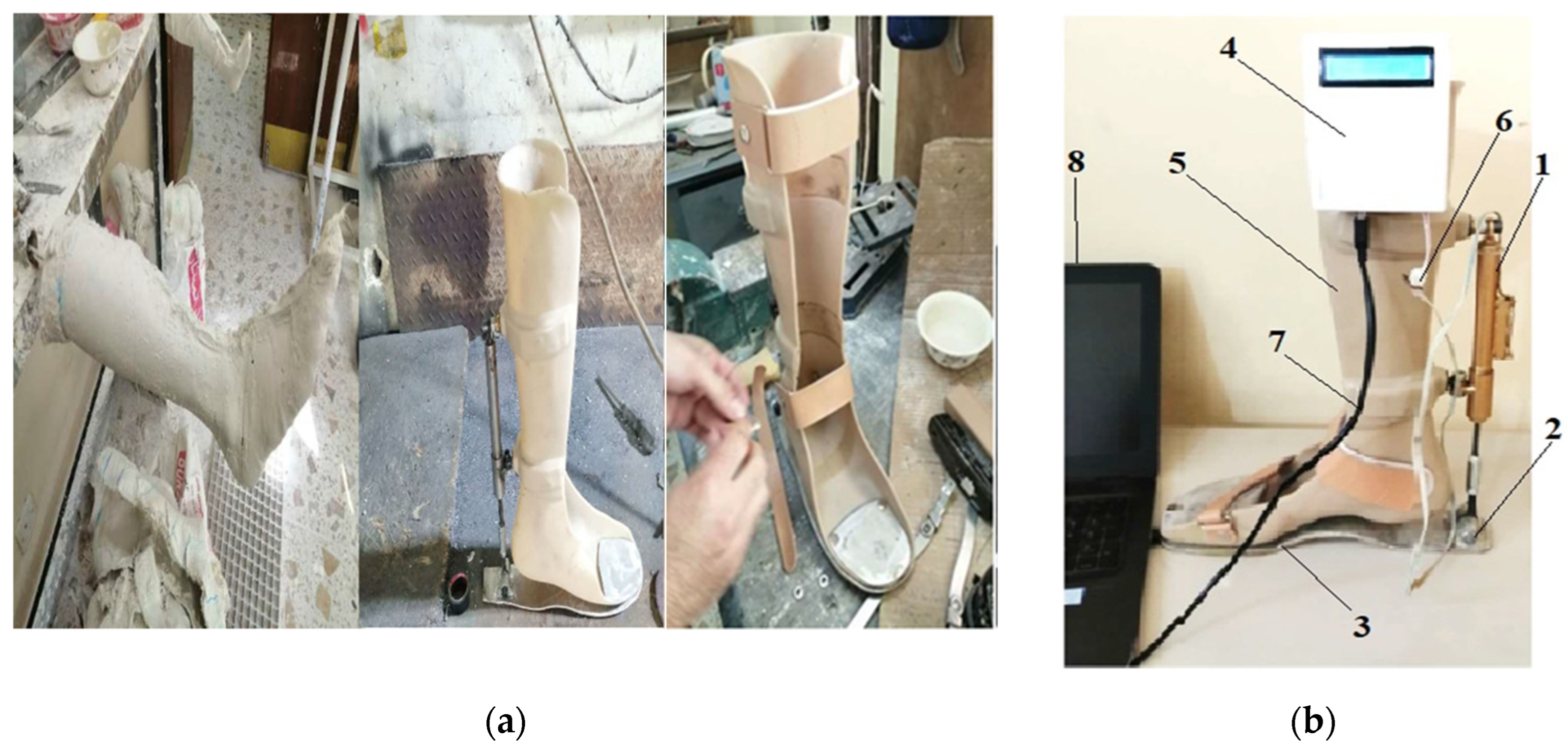
- Creation of an active orthosis with simplified mechanics: The orthosis features an intuitive and streamlined design, enhancing ease of use for patients. An adjustment lever, mounted on the ankle joint, enables users to independently customize the device to their specific needs without requiring complex configurations.
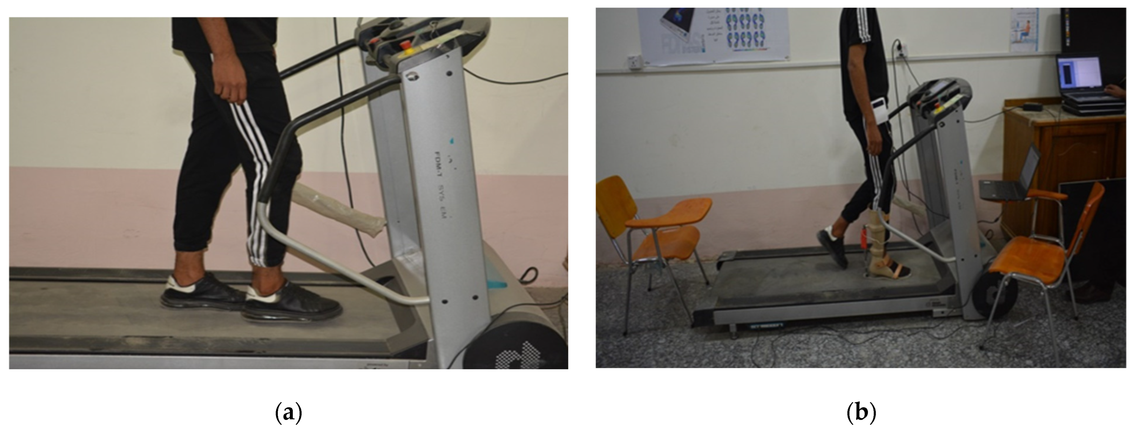
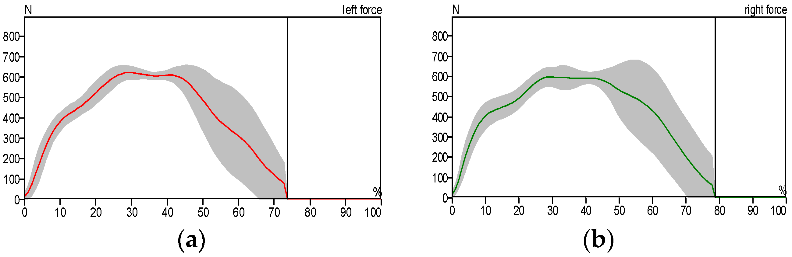
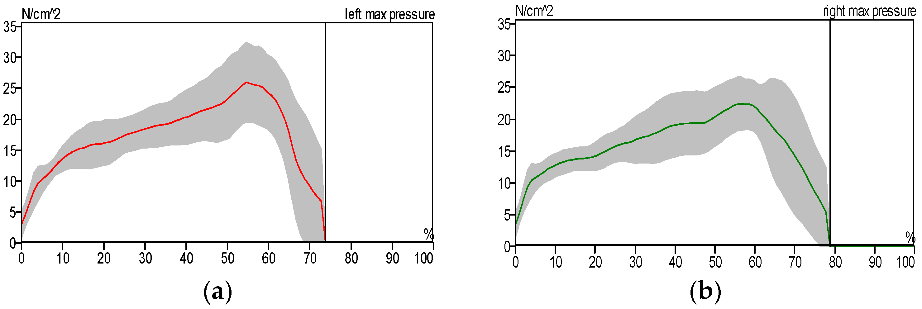
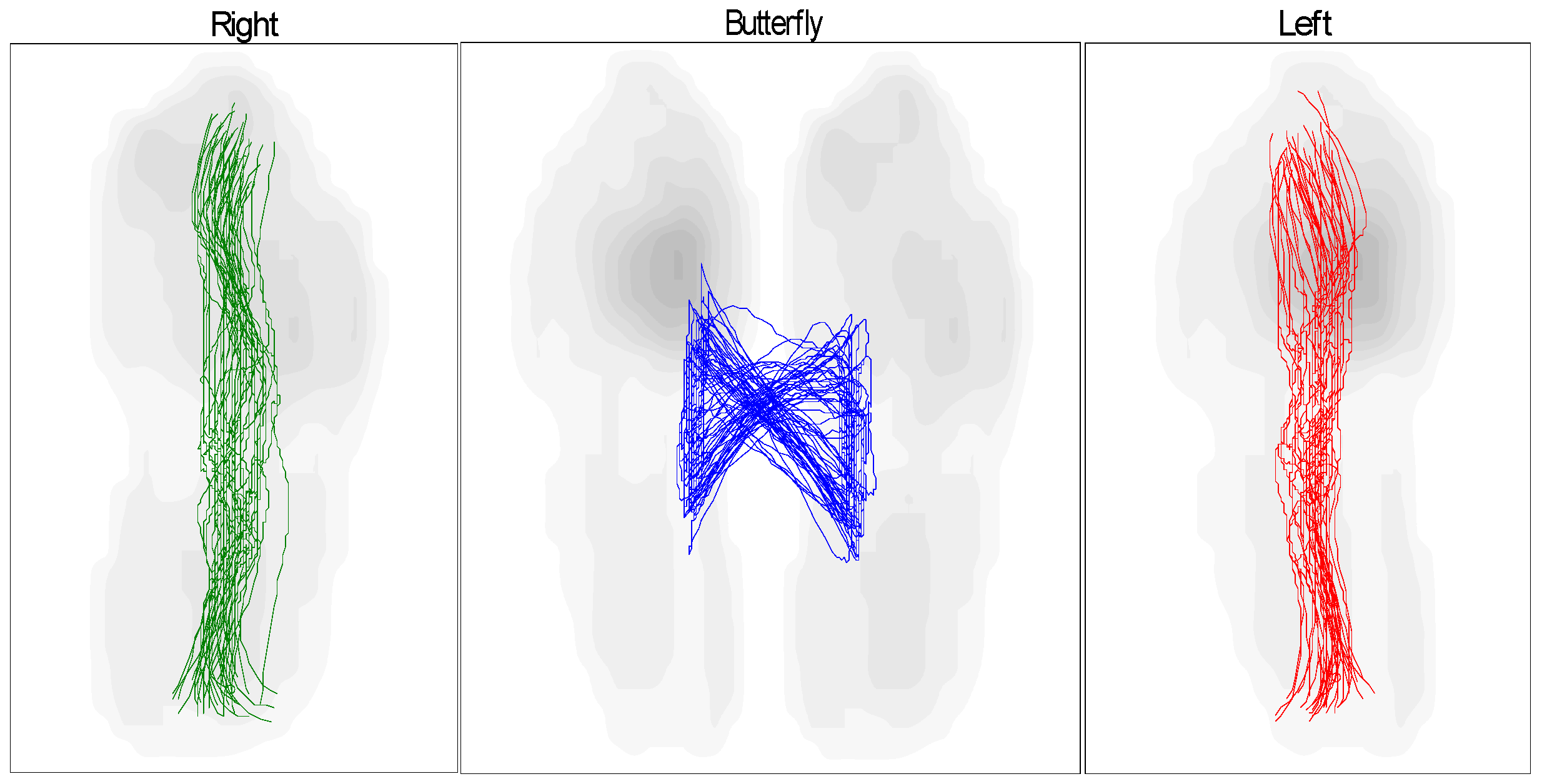
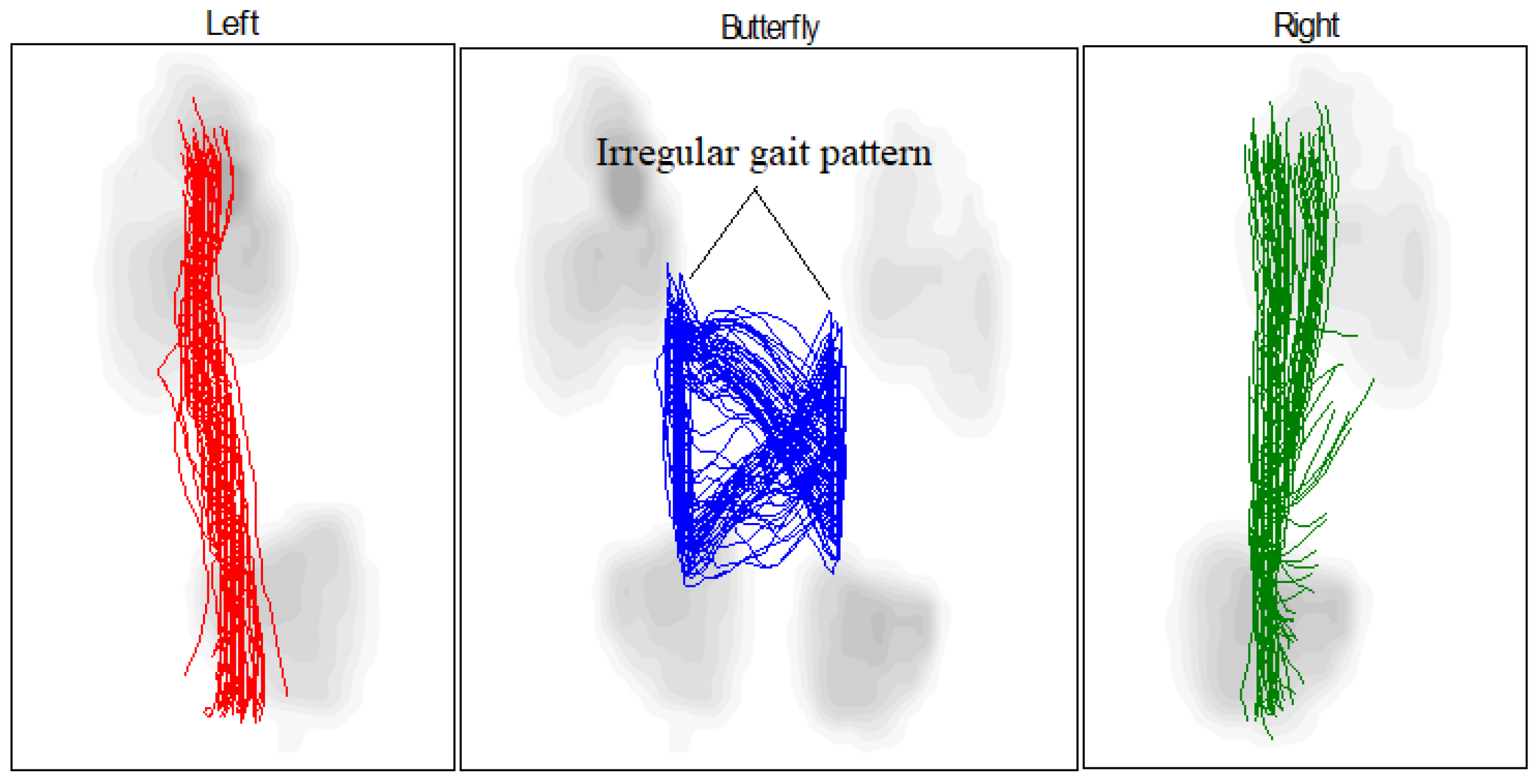
- Compliance with biomechanical requirements: Treadmill tests have shown that the orthosis facilitates movement closely resembling that of a healthy foot. This is supported by the results of the “butterfly” test, which compares the gait patterns of the patient wearing the exoskeleton to those of a healthy individual.
2. Materials and Methods
- Semi-rigid material and high temperature resistance;
- Transparent material and high chemical resistance;
- Durable material and high wear resistance;
- Low cost.
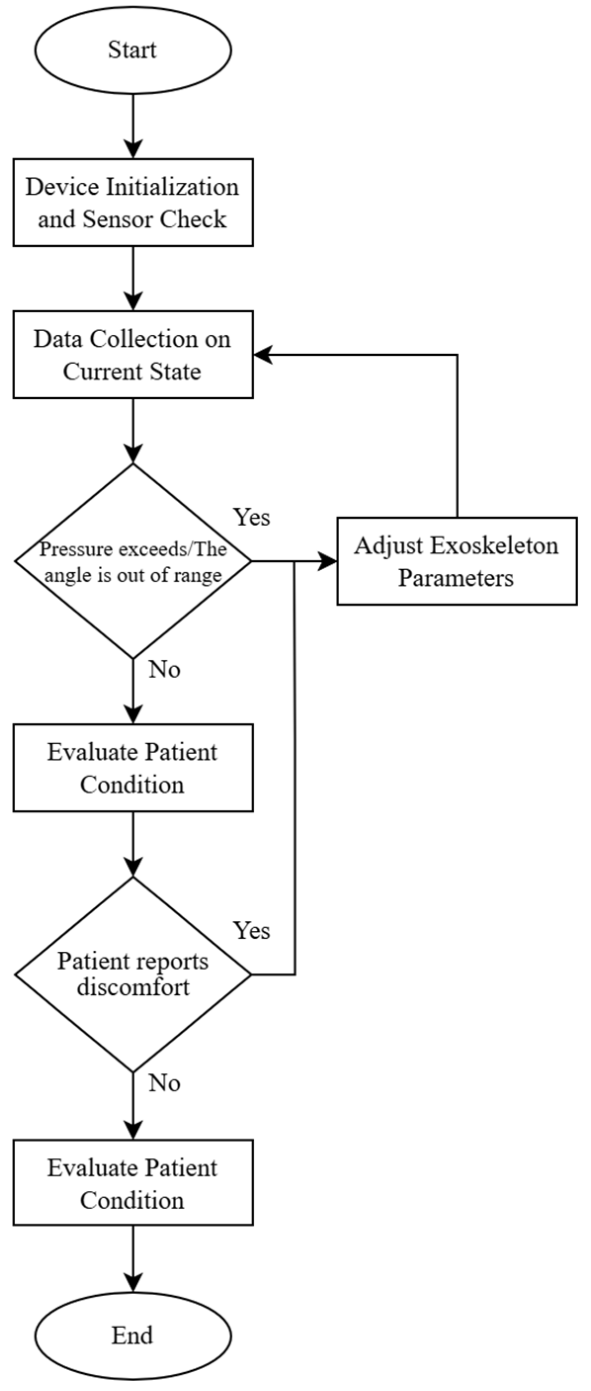
- Start.
- Device Initialization and Sensor Check:
- If sensors are functional, proceed to the next step;
- If sensor errors are detected, trigger an error alert and terminate the operation.
- Data Collection on Current State (pressure, flexion angle):
- Calculate force F;
- If pressure and force are within the acceptable range, proceed to step 5;
- If pressure exceeds the range or the angle is out of range, proceed to step 4.
- Adjust Exoskeleton Parameters:
- Adjust the angle or pressure to ensure load values are within acceptable limits;
- Return to step 3 to remeasure.
- Evaluate Patient Condition:
- If the patient reports discomfort, proceed to step 4 for adjustment;
- If the patient is comfortable, proceed to step 6.
- Save Data and Complete Cycle.
- End Cycle.
3. Experimental Work
4. Results and Discussion
5. Conclusions
- This study successfully designed and fabricated a prototype exoskeleton device that integrates the kinetic properties of both fixed and mobile orthoses. The device facilitated an in-depth investigation of the interaction between the exoskeleton and its operator, including tests with healthy individuals and patients with ankle injuries.
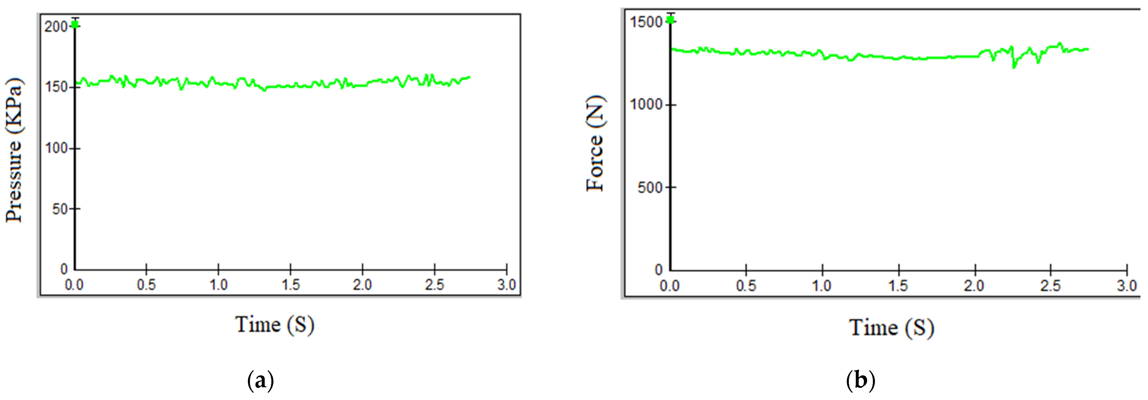
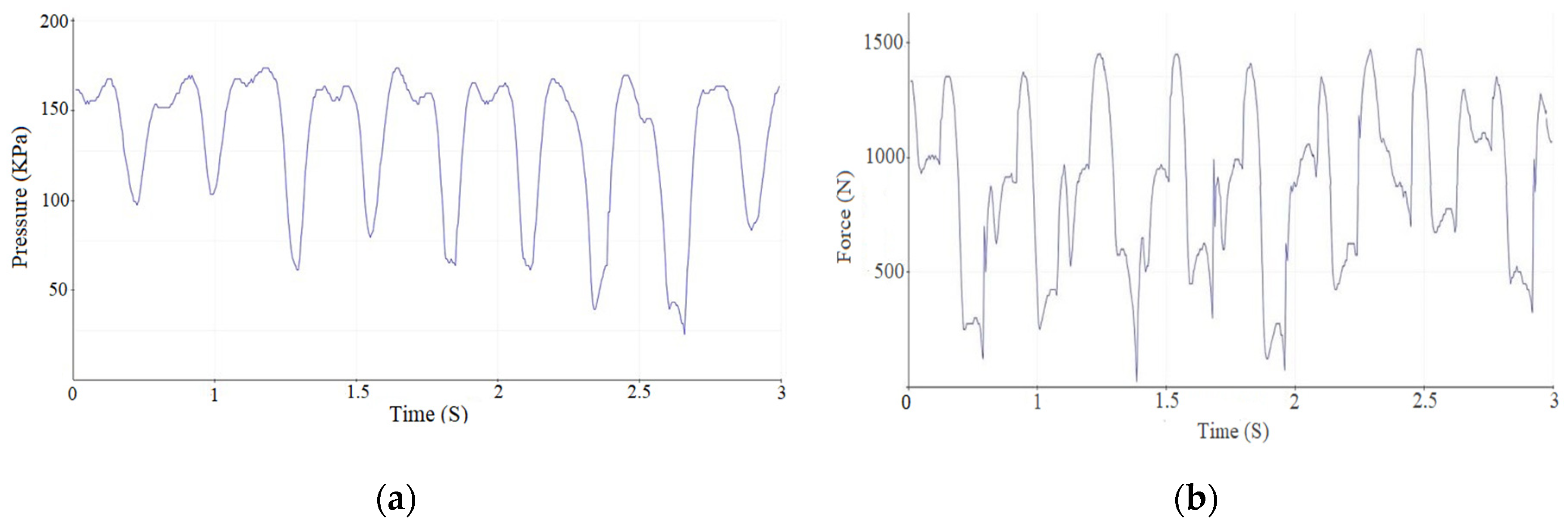
- The exoskeleton significantly enhanced gait parameters in patients. Experimental results demonstrated that the patients’ gait patterns approached normal levels when utilizing the exoskeleton. Furthermore, performance comparisons revealed that the custom-built electromechanical sensor (EMS) achieved results comparable to the commercially available F-Socket sensor, with maximum pressure and force measurements of 156 kPa and 1335 N for the F-Socket sensor, and 152 kPa and 1328 N for the EMS sensor. The EMS sensor exhibited sufficient accuracy for rehabilitation purposes.
- This work established causal relationships between the motor activity of the ankle joint and the movement of exoskeleton components, highlighting the mechanical synergy between the patient’s movements and the device’s functionality.
- The primary objectives of this study—reducing ankle joint loads, accelerating recovery phases, and ensuring joint protection—were effectively achieved. The analysis based on butterfly-type graph metrics demonstrated notable improvements in gait parameters for patients with pathological conditions, affirming the device’s operational effectiveness.
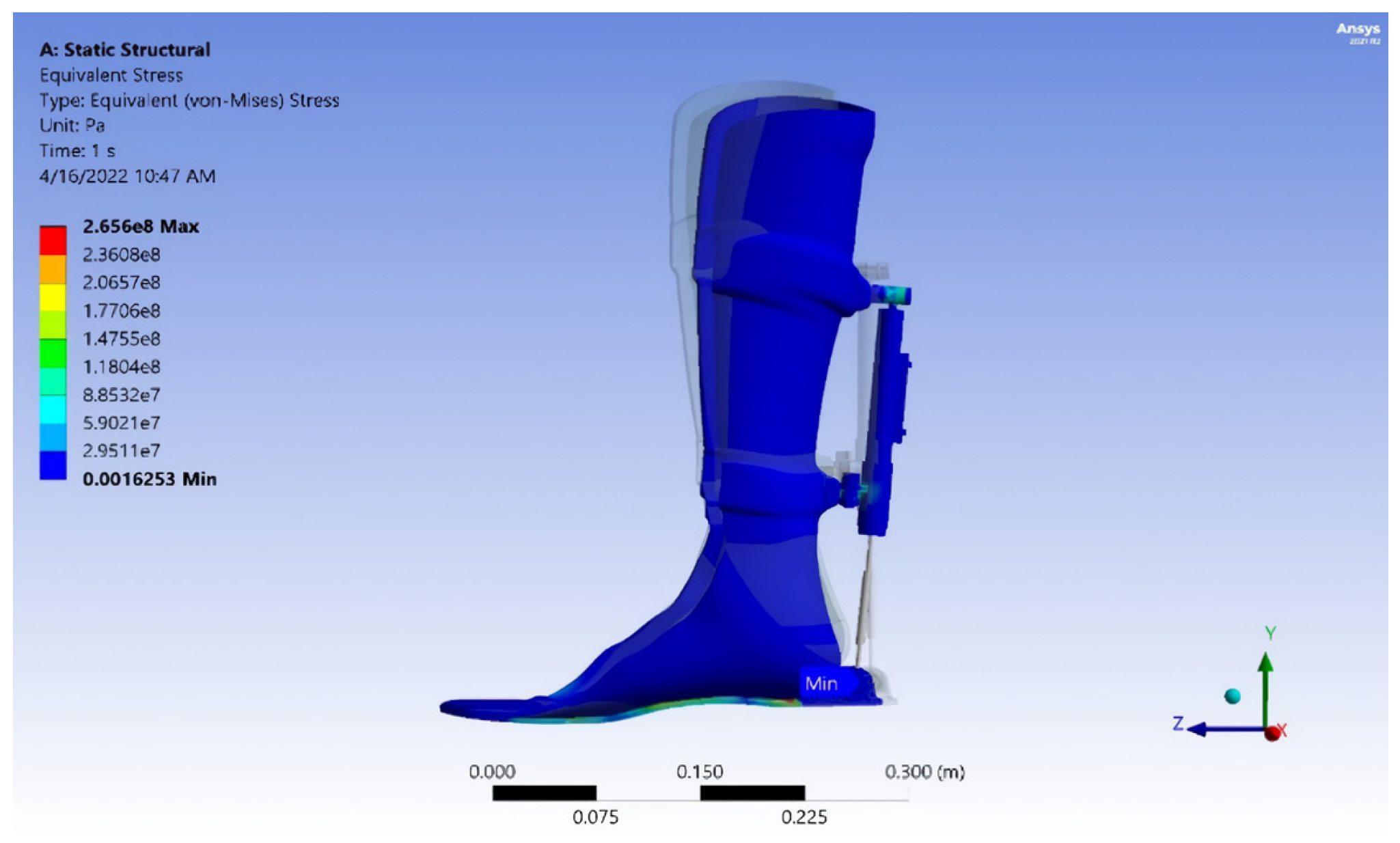
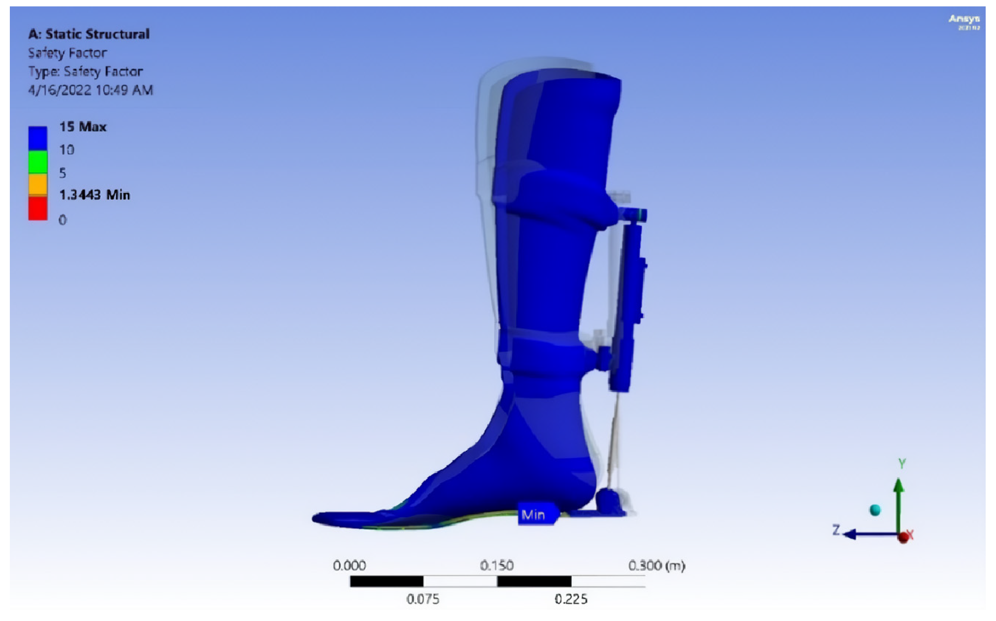
- The exoskeleton’s performance was verified through comprehensive mechanical testing, including von Mises stress analysis, strain evaluation, fatigue safety margin assessment, and projected service life estimation. The calculated durability suggests a lifespan of approximately 40,447 gait cycles, or 5.5 years, assuming three rehabilitation sessions per week with 150 steps per session. This underscores the exoskeleton’s long-term utility and robustness in rehabilitation therapy.
Author Contributions
Funding
Institutional Review Board Statement
Informed Consent Statement
Data Availability Statement
Conflicts of Interest
References
- Wu, H.; Li, Y. A Gripper Force Sensing Device for Collaborative Manipulator Based on Force Sensitive Resistor. In Computational and Experimental Simulations in Engineering; Springer: Cham, Switzerland, 2024. [Google Scholar] [CrossRef]
- Sun, X.; Chen, W.; Xiong, X.; Chen, W.; Jin, Y. A Variable Configuration Force Sensor With Adjustable Resolution for Robotic Applications. IEEE Trans. Ind. Electron. 2023, 70, 2066–2075. [Google Scholar] [CrossRef]
- Chen, X.; Sathyanarayan, H.; Gong, Y.; Yi, J.; Wang, H. Dynamic Tire/Road Friction Estimation With Embedded Flexible Force Sensors. IEEE Sens. J. 2023, 23, 26608–26619. [Google Scholar] [CrossRef]
- Rathore, R.; Singh, A.K.; Chaudhary, H.; Kandan, K. Gait Abnormality Detection in Unilateral Trans-Tibial Amputee in Real-Time Gait Using Wearable Setup. IEEE Sens. J. 2023, 23, 12567–12573. [Google Scholar] [CrossRef]
- Shivani, S.A.; Sri, S.B.; Krishnakumar, S. Smart Gadget for Tracking and Primary Treatment of Diabetic Foot Ulcers. In Proceedings of the 7th International Conference on Intelligent Computing and Control Systems (ICICCS), Madurai, India, 17–19 May 2023; pp. 917–921. [Google Scholar] [CrossRef]
- Belinsky, A.V.; Devishvili, V.M.; Chernorizov, A.M.; Lobin, M.A. Hardware-Software Complex for Strain-Tremorometric Measurements in Psychophysiological Studies. Russ. Psychol. J. 2023, 2, 1. [Google Scholar] [CrossRef]
- Toedtheide, A.; Chen, X.; Sadeghian, H.; Naceri, A.; Haddadin, S. A Force-Sensitive Exoskeleton for Teleoperation: An Application in Elderly Care Robotics. In Proceedings of the IEEE International Conference on Robotics and Automation (ICRA), London, UK, 29 May–2 June 2023; pp. 12624–12630. [Google Scholar] [CrossRef]
- Liu, L.; Liu, J.; Wang, R.; Li, X.; Guo, H.; Tang, J.; Liu, J. Electromagnetic Interference Shielding Performance of CNT Sponge/PDMS Force-Sensitive Composites. J. Electron. Mater. 2023, 52, 429–436. [Google Scholar] [CrossRef]
- Zhang, R.; Zhai, Q.; Bao, F.; Zhao, D.; Lu, Z.; Wang, J.; Wang, W. A Highly Stretchable Force Sensitive and Temperature Sensitive Sensor Material with the Sandwich Structure of PDMS + PDMS/GaInSn + PDMS. Polymers 2023, 15, 3776. [Google Scholar] [CrossRef] [PubMed]
- Chen, D.; Cai, Y.; Cheng, L.; Guo, S.; Liu, T.; Huang, S.; Yu, H.; Wang, Y.; Hu, Z.; Gui, D. Structure and Function Design of Carbon Nanotube-Based Flexible Strain Sensors and Their Application. Measurement 2024, 225, 113992. [Google Scholar] [CrossRef]
- Andrade, R.L.; Figueiredo, J.; Fonseca, P.; Vilas-Boas, J.P.; Silva, M.T.; Santos, C.P. Human-Robot Joint Misalignment, Physical Interaction, and Gait Kinematic Assessment in Ankle-Foot Orthoses. Sensors 2024, 24, 246. [Google Scholar] [CrossRef] [PubMed]
- Wang, C.; He, T.; Zhou, H.; Zhang, Z.; Lee, C. Artificial Intelligence Enhanced Sensors: Enabling Technologies to Monitor and Manage COVID-19. Bioelectron. Med. 2023, 9, 18. [Google Scholar] [CrossRef] [PubMed]
- Sabry, F.; Eltaras, T.; Labda, W.; Alzoubi, K.; Malluhi, Q. Machine Learning for Healthcare Wearable Devices: The Big Picture. J. Healthc. Eng. 2022, 2022, 9038375. [Google Scholar] [CrossRef] [PubMed]
- Yang, S.; Koo, B.; Lee, S.; Jang, D.-J.; Shin, H.; Choi, H.-J.; Kim, Y. Determination of Gait Events and Temporal Gait Parameters for Persons with a Knee–Ankle–Foot Orthosis. Sensors 2024, 24, 964. [Google Scholar] [CrossRef] [PubMed]
- Fang, M.; Ivanisevic, J.; Benton, H.P.; Johnson, C.H.; Patti, G.J.; Hoang, L.T.; Urit-boonthai, W.; Kurczy, M.E.; Siuzdak, G. Detection of Various Microplastics in Patients Undergoing Cardiac Surgery. Anal. Chem. 2015, 87, 10935–10941. [Google Scholar] [CrossRef] [PubMed]
- Yang, Y.; Xie, E.; Du, Z.; Peng, Z.; Han, Z.; Li, L.; Zhao, R.; Qin, Y.; Xue, M.; Li, F.; et al. Detection of Various Microplastics in Patients Undergoing Cardiac Surgery. Environ. Sci. Technol. 2023, 57, 10911–10918. [Google Scholar] [CrossRef] [PubMed]
- Laic, G.; Firouzi, M.; Claeys, R.; Bautmans, I.; Swinnen, E.; Beckwée, D. A State-of-the-Art of Exoskeletons in Line with the WHO’s Vision on Healthy Aging: From Rehabilitation of Intrinsic Capacities to Augmentation of Functional Abilities. Sensors 2024, 24, 2230. [Google Scholar] [CrossRef] [PubMed]
- Wang, X.; Wang, H.; Zhang, B.; Zheng, D.; Yu, H.; Cheng, B.; Niu, J. A Multistage Hemiplegic Lower-Limb Rehabilitation Robot: Design and Gait Trajectory Planning. Sensors 2024, 24, 2310. [Google Scholar] [CrossRef] [PubMed]
- Hussein, T.S.; Izyumov, A.I. Microprocessor System for Measuring Pressure between Orthosis and Foot. Syst. Methods Technol. 2023, 1, 80–86. [Google Scholar] [CrossRef]
- Hussein, T.S.; Iziumov, A.I. Measurement of Force Parameters for Human Gait Research. Syst. Methods Technol. 2023, 2, 30–37. [Google Scholar] [CrossRef]
- Hussein, T.S.; Iziumov, A.I. Microprocessor System of the Human Movement Parameters Control. Assem. Mech. Eng. Instrum. Eng. 2023, 24, 246–252. [Google Scholar] [CrossRef]
- 4th International Scientific Conference of Engineering Sciences and Advances Technologies (IICESAT). Available online: http://2022.iicesat.com/ (accessed on 1 May 2024).
- Perry, J. Gait Analysis: Normal and Pathological Function; SLACK Inc.: West Deptford, NJ, USA, 1992. [Google Scholar]
- Perry, J. Normal and Pathological Gait. In Atlas of Orthoses and Assistive Devices; Eversmann, W., Fisk, J., Goldberg, B., Hsu, J., Lonstein, J., Michael, J., Moore, T., Eds.; Mosby: Boston, MA, USA, 1997; pp. 67–91. [Google Scholar]


| Measurement Method | Intervention Pressure, (KPa) | Force (N) |
|---|---|---|
| F-Socket sensor | 156 | 1335 |
| Measurement Method | Intervention Pressure, (KPa) | Force (N) |
|---|---|---|
| Manufactured EMS sensor | 152 | 1328 |
| Left | Right | |
|---|---|---|
| Gait line length, mm | 12 | 15 |
| Single support line, mm | 14 | 15 |
| Ant/post position, mm | 154 | |
| Ant/post variability, mm | 9 | |
| Lateral symmetry, mm | −21 | |
| Lateral variability, mm | 17 | |
| Left | Right | |
|---|---|---|
| Gait line length, mm | 11 | 43 |
| Single support line, mm | 12 | 17 |
| Ant/post position, mm | 149 | |
| Ant/post variability, mm | 19 | |
| Lateral symmetry, mm | 36 | |
| Lateral variability, mm | 19 | |
| Left | Right | |
|---|---|---|
| Gait line length, mm | 99 | 110 |
| Single support line, mm | 31 | 30 |
| Ant/post position, mm | 120 | |
| Ant/post variability, mm | 35 | |
| Lateral symmetry, mm | −26 | |
| Lateral variability, mm | 74 | |
Disclaimer/Publisher’s Note: The statements, opinions and data contained in all publications are solely those of the individual author(s) and contributor(s) and not of MDPI and/or the editor(s). MDPI and/or the editor(s) disclaim responsibility for any injury to people or property resulting from any ideas, methods, instructions or products referred to in the content. |
© 2025 by the authors. Licensee MDPI, Basel, Switzerland. This article is an open access article distributed under the terms and conditions of the Creative Commons Attribution (CC BY) license (https://creativecommons.org/licenses/by/4.0/).
Share and Cite
Iziumov, A.; Hussein, T.S.; Kosenko, E.; Nazarov, A. Adaptive Exoskeleton Device for Stress Reduction in the Ankle Joint Orthosis. Sensors 2025, 25, 832. https://doi.org/10.3390/s25030832
Iziumov A, Hussein TS, Kosenko E, Nazarov A. Adaptive Exoskeleton Device for Stress Reduction in the Ankle Joint Orthosis. Sensors. 2025; 25(3):832. https://doi.org/10.3390/s25030832
Chicago/Turabian StyleIziumov, Andrey, Talib Sabah Hussein, Evgeny Kosenko, and Anton Nazarov. 2025. "Adaptive Exoskeleton Device for Stress Reduction in the Ankle Joint Orthosis" Sensors 25, no. 3: 832. https://doi.org/10.3390/s25030832
APA StyleIziumov, A., Hussein, T. S., Kosenko, E., & Nazarov, A. (2025). Adaptive Exoskeleton Device for Stress Reduction in the Ankle Joint Orthosis. Sensors, 25(3), 832. https://doi.org/10.3390/s25030832