OpenCHIRP: A Low-Cost, Lightweight Sub-Bottom Profiler for Shallow Water Environments Suitable for Autonomous Vehicles
Highlights
- Development of an innovative sub-bottom profiler for acquiring seismic reflection data in shallow-water environments.
- Key characteristics: low cost, lightweight, and compatible with autonomous vehicles.
- Extensive use of open hardware and software, with code and assembly instructions provided in the article.
- Enables seafloor and subseafloor pseudo-3D and 4D (repeated) mapping.
Abstract
1. Introduction
2. Materials and Methods
2.1. Hardware
- Signal Quality and Power: The generated signal must be of high quality and have sufficient power to penetrate adequately beneath the seafloor.
- Hydrophone Sensitivity: The hydrophone must be sensitive enough to accurately capture the weak reflected signal from the seafloor.
- Noise Reduction: The hydrophone receives not only the reflected signal but also ambient acoustic noise; effective methods are needed to mitigate this interference.
2.1.1. Mainboard
- -
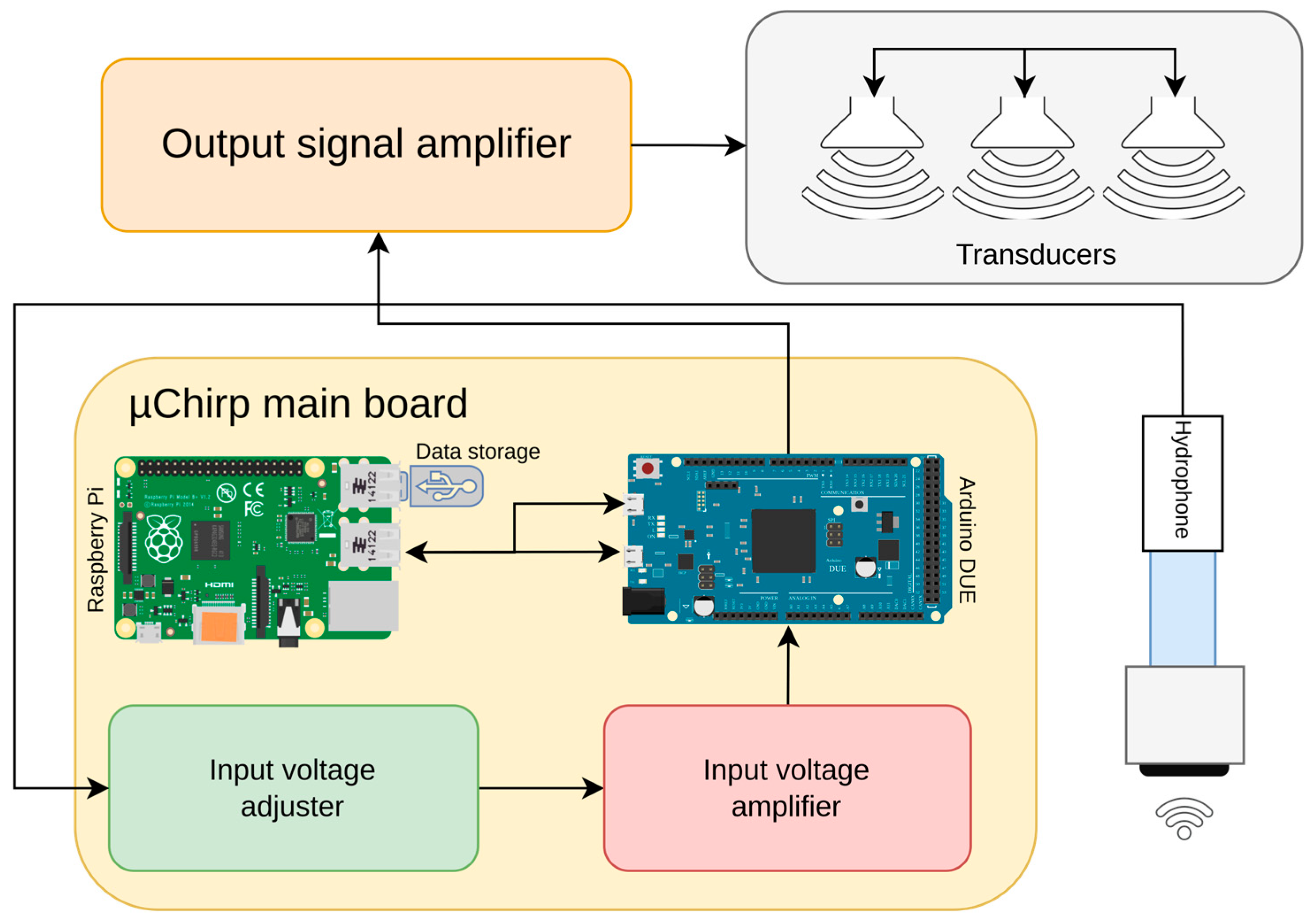
- Receives, via its primary USB port, the start and end frequencies, the pulse length of the signal to emit, and the emission rate of the pulses.
- -
- Builds the waveform to emit based on user parameters.
- -
- Emits the waveform at the specified rate through one of its DAC ports.
- -
- Simultaneously receives the signal from the hydrophone and sends it to its secondary USB port.
- -
- Instructs the Arduino DUE on the signal to emit.
- -
- Collects data sent by the Arduino DUE.
- -
- Acquires real-time position data from a GPS device.
- -
- Saves the geo-referenced data in a standard format on a USB disk.
- -
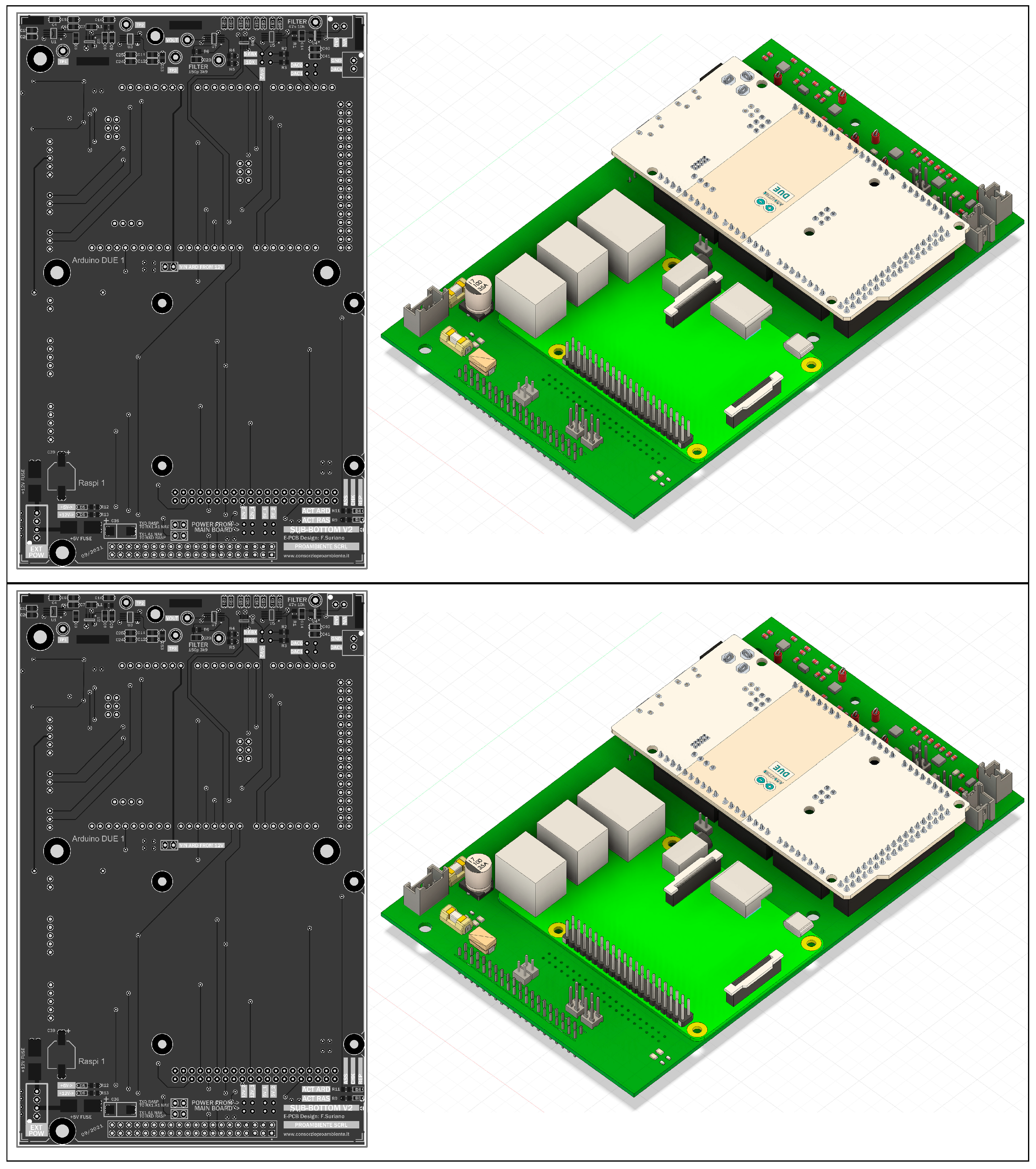
- Fused power supply equipped for external input of 5 and 12 V;
- -
- Raspberry Pi and Arduino DUE slot for easy access and maintenance;
- -
- Hydrophone signal processing: Custom voltage adjustment and gain amplifier programmable in real-time by the Arduino DUE;
- -
- Expansion ports for additional integrations.
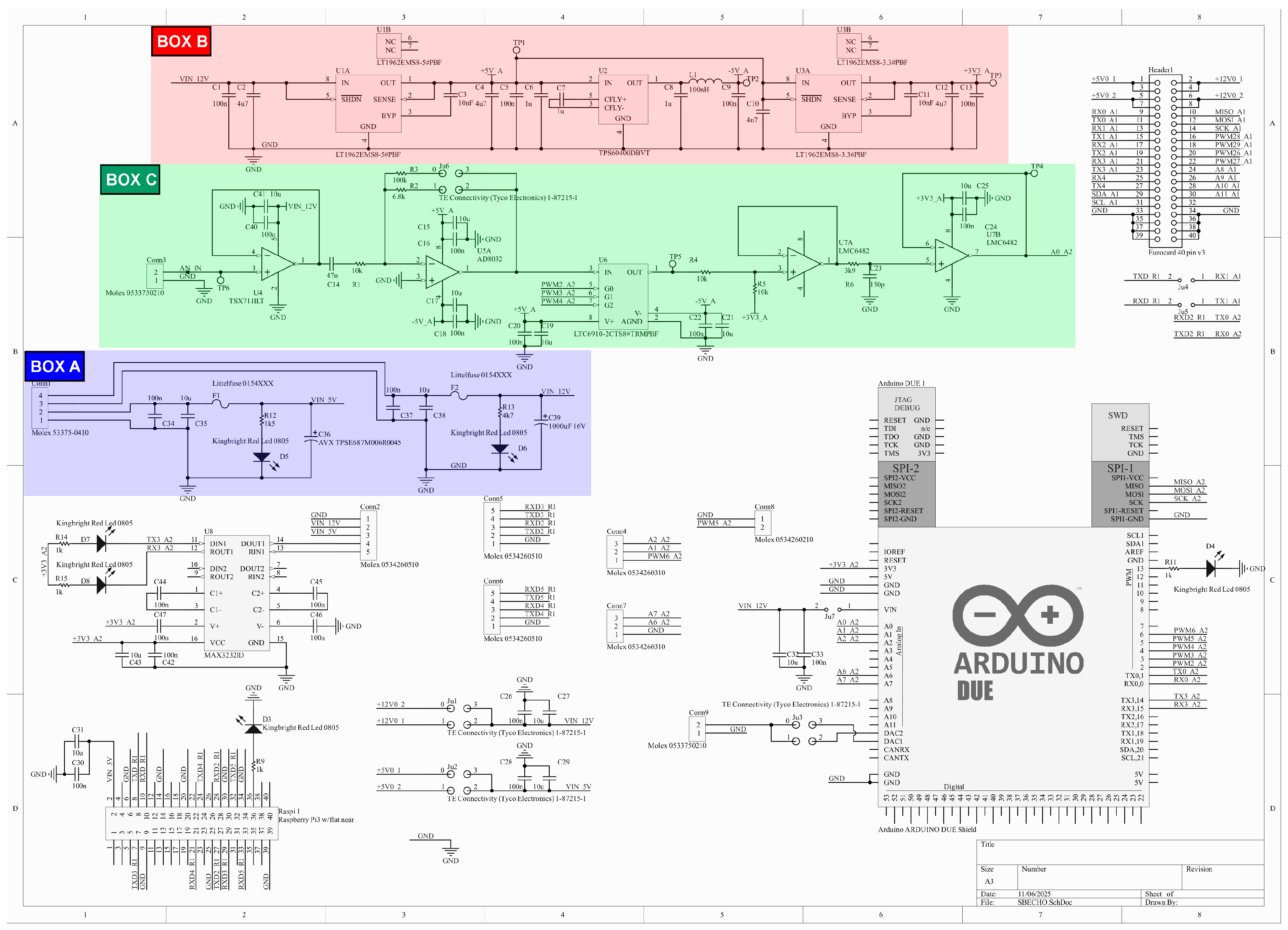
- A supply section (box A—Figure 2), designed to accept both 5 and 12 V on two separate rails and using a pre-crimped 4-pin connector. Decoupling and bypass capacitors are added, as well as interchangeable bottle fuse (default 3 A) and an SMD led for power-on tracking. No reverse polarity protection is provided in this board release.
- A specific low-noise regulated voltage section (box B—Figure 2), dedicated to the signal conditioning section (box C—Figure 2, described in iii.). This section, along with the connected signal conditioning part (iii.), ensures that interferences and noise affecting the hydrophone signal are kept as low as possible, thus enhancing the signal quality. The circuit design, along with the selection of components and integrated circuits (ICs) has been made to receive a signal from the hydrophone in the [6 ± 3] V range, and it can be easily reconfigured for different input signal ranges. Low-noise and low-dropout voltage regulators from LT technologies have been selected (for 5 V—IC U1A and 3.3 V—IC U3A) considering their market availability and their package (MSOP); the latter allows easy component swap and circuit reconfiguration. The IC U2 provides the −5 V voltage necessary for the proper signal conditioning (iii.). Passive components (C, R, L) are here used following manufacturers’ suggestions to make the regulation circuit work properly. Service test points are included on the PCB layout to check the regulated voltages.
- A conditioning section for the hydrophone signal (box C—Figure 2) that provides voltage adjustment and amplification of the input signal, labeled on the schematic as AN_IN, coming from a 2-pin pre-crimped connector. The hydrophone signal is first fed to IC U4, a single-channel operational amplifier (rail-to-rail and high voltage span, for potential system reconfiguration), used as a voltage buffer (for signal stabilization and impedance matching). It is connected to a first-order high-pass filter with a cutoff frequency of about 400 Hz. The filter and its capacitor block the DC offset, so the signal input to op-amp U5 is in the [0 ± 3] V range. U5, in inverting configuration, provides the first hardware signal amplification according to the JP6 jumper position. R2 and R3 resistors define the amplification factor, by default 0.68× (via R2) and 10× (via R3). Then, software amplification, controlled by the Arduino DUE board, is applied through IC U6: a programmable gain inverting amplifier (LTC6910, gain 0÷64, selected via 3 digital signals). The signal is then shifted around 1.65 V (op-amp U7A; U7 is a dual-channel, rail-to-rail, low-noise operational amplifier LTC6910) to ensure proper reading by the Arduino DUE Analog-to-Digital Converter. The shifted signal passes through a first-order low-pass filter (cutoff frequency about 52 kHz) and a voltage buffer (U7B) before being wired to the Arduino DUE at label A0_A2. Service test points are placed in section iii, as well as exposed ground pads to add a ground shield and reduce external interference. Bypass and decoupling capacitors are placed for all the ICs used.
- The Arduino DUE, Raspberry Pi, and additional connectors section (all parts not included in BOX A, B, and C—Figure 2) includes headers for easy maintenance and substitution of the Arduino and Raspberry Pi, as well as multiple connectors for customization and feature expansion. The available expansion ports are 1× RS232 port, 3× UART ports, 2× analog inputs (0–3.3 V), and 2 TTL digital I/O. Status LEDs are connected to the digital I/O of the Raspberry Pi and Arduino to provide information about the proper system operation. An additional header connector is also placed on the PCB to ensure compatibility with previous OpenSWAP hardware and for debugging purposes.
2.1.2. Seismic Reflection Signal Generation System
2.2. Software
2.2.1. The Firmware
- -
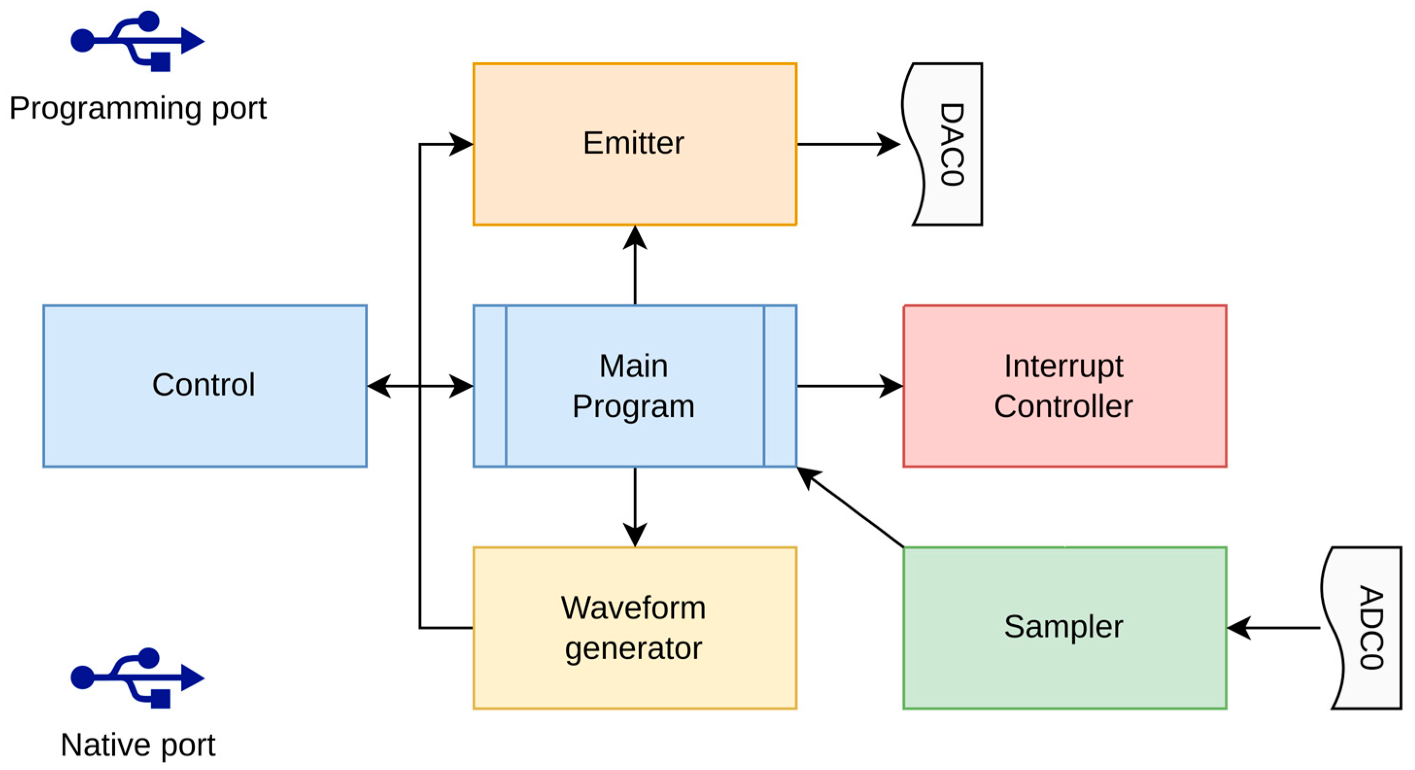
- The DAC0 (Digital Analog Converter) port for emitting the waveform towards the amplified transducers.
- -
- The ADC (Analog Digital Converter) A0 port for sampling the signal received by the hydrophone.
2.2.2. The CiapCiap Program
2.2.3. The “Params” File
2.2.4. The Hosting Operating System
- (1)
- Login by SSH to OpenCHIRP.
- (2)
- Execute RW.SH to make the folder writable.
- (3)
- Edit the files for acquisition parameters.
- (4)
- Kill ciapciap.
- (5)
- Execute RO.SH to make the folder read-only again.
2.2.5. The Boot Process
- -
- prologue.sh: Prepares the execution environment, sets global environment variables, and checks existing file systems for consistency.
- -
- start_net.sh: Starts the network and configures the access point.
- -
- start_acq.sh: Starts the acquisition process.
3. Results
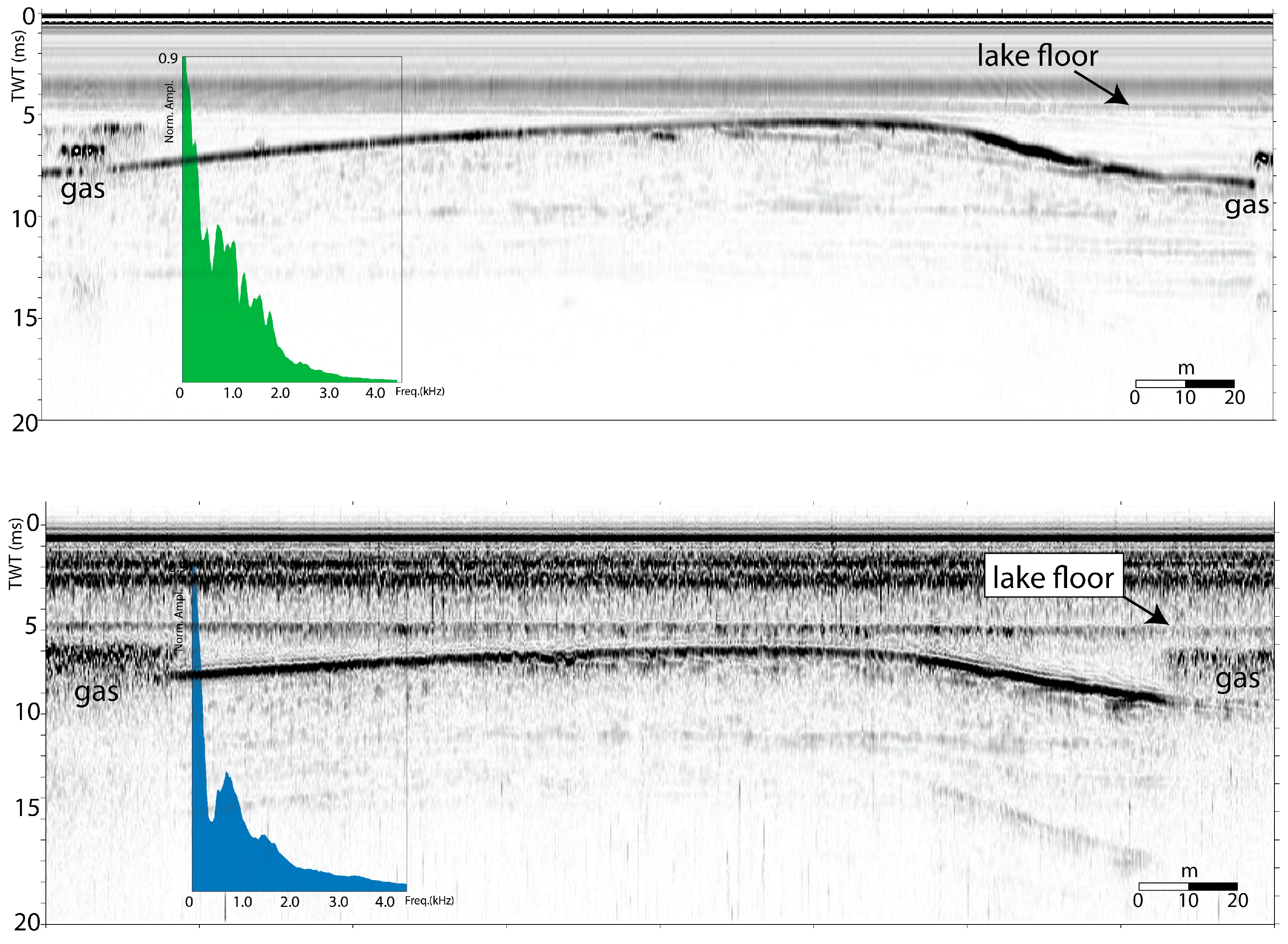
3.1. Setup-1
3.2. Setup-2
4. Conclusions
Supplementary Materials
Author Contributions
Funding
Data Availability Statement
Conflicts of Interest
Abbreviations
| ASV | Autonomous Surface Vehicle |
| SBP | Sub-bottom Profiler |
Appendix A
- NAME/TYPE STRING: The name of the instrument, typically CHIRP.
- INPUT UDP PORT/TYPE NUMERIC: The port to listen for incoming commands. An external program can send commands to CiapCiap to control the acquisition process.
- -
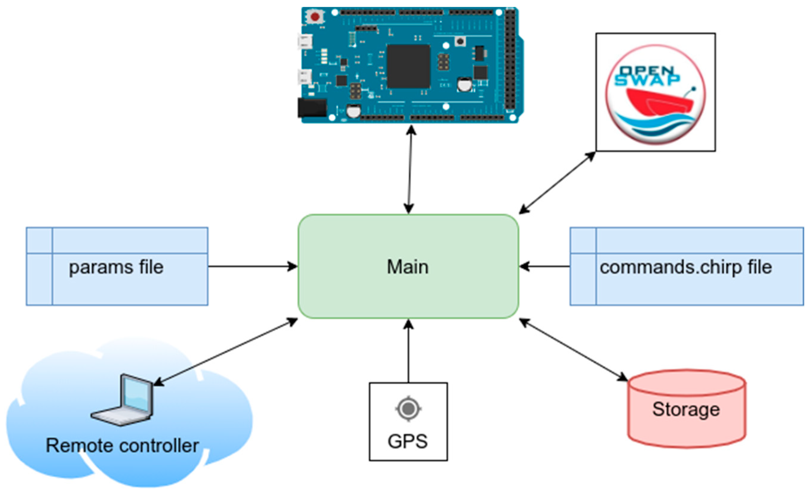
- UDP PORT OF MONITORING APP/TYPE NUMERIC: The port to send received data for remote monitoring. When CiapCiap acquires new data, it stores it in SEGY format inside the internal storage device and then sends a subset of that data to a listening application over the Internet (or intranet).
- 3.
- TCP/IP ADDRESS OF MONITORING APP/TYPE IP_ADDRESS: The IP address of the host running the monitoring application.
- -
- TRACES DECIMATION/TYPE NUMERIC: The traces decimation factor. This parameter specifies how many of the traces collected during the acquisition process must be sent to the listening application over the Internet, allowing to limit the outgoing traffic.
- -
- DATA DECIMATION/TYPE BOOLEAN: The data decimation factor. This parameter allows for further reduction in the data sent over the Internet. If the value 1 is specified, the trace will be resampled to 512 bytes before sending it.
- 4.
- DATA FOLDER/TYPE STRING: The directory where SEGY files are stored.
- -
- FILENAME PREFIX/TYPE STRING: The prefix of the filename of the stored data. The full filename includes a date stamp, time stamp, and the suffix “.SEG.”
- 5.
- SPLIT EVERY BYTES/TYPE NUMERIC: The maximum allowed size in bytes of a file.
- -
- μChirp COMMANDS FILE/TYPE STRING: The filename containing commands to set the μChirp parameters.
- 6.
- UNUSED.
- 7.
- UNUSED.
- -
- DUNVAG SERIAL DEVICE/TYPE PATH: The device to which the OpenSWAP vehicle is connected. Used when installed inside an OpenSWAP Autonomous Vehicle.
- -
- BAUD/TYPE NUMERIC: The baud rate of the serial connection to Dunvag.
- 8.
- DATA BITS/TYPE NUMERIC: The data bits of the serial connection to Dunvag.
- 9.
- PARITY/TYPE CHAR: The parity of the serial connection to Dunvag.
- 10.
- STOP BITS/TYPE NUMERIC: The stop bits of the serial connection to Dunvag.
- 11.
- GPS SERIAL DEVICE/TYPE PATH: The device to which the GPS is connected.
- -
- BAUD/TYPE NUMERIC: The baud rate of the serial connection to GPS.
- 12.
- DATA BITS/TYPE NUMERIC: The data bits of the serial connection to GPS.
- 13.
- PARITY/TYPE CHAR: The parity of the serial connection to GPS.
- 14.
- STOP BITS/TYPE NUMERIC: The stop bits of the serial connection to GPS.
- 15.
- BOTTOM TRACKING START SEARCH/TYPE NUMERIC: The starting point to search the bottom in ms. This parameter must be set to −1 for sub-bottom operation to disable bottom-tracking.
- 16.
- STEP_FUNCTION_LENGTH/TYPE NUMERIC: The step function length in the number of samples to use for bottom tracking. Unused for sub-bottom operation. 25–30. Unused Parameters for bottom tracking.
- 17.
- GPS PORT/TYPE NUMERIC: The port at which to start a GPS service.
References
- Bull, J.M.; Quinn, R.; Dix, J.K. Reflection Coefficient Calculation from Marine High-Resolution Seismic Reflection (CHIRP) Data and Application to an Archaeological Case Study. Mar. Geophys. Res. 1998, 20, 1–11. [Google Scholar] [CrossRef]
- Plets, R.M.K.; Dix, J.K.; Adams, J.R.; Best, A.I. 3D reconstruction of a shallow archaeological site from high-resolution acoustic imagery: The Grace Dieu. Appl. Acoust. 2008, 69, 399–411. [Google Scholar] [CrossRef]
- Boldreel, L.O.; Grøn, O.; Tayong, R.B.; Madsen, B.; Bennike, O.; Andersen, M.S. A Submerged and Buried Mesolithic Site off Svanemøllen Harbor, Copenhagen, Denmark: Acoustic Detection (Human-Altered Lithic Detection) and Verification by Means of Coring. Remote Sens. 2025, 17, 413. [Google Scholar] [CrossRef]
- Schock, S.G.; LeBlanc, L.A.; Satchidanarda, P. Sediment Classification Using the CHIRP Sonar. In Proceedings of the Offshore Technology Conference, Houston, TX, USA, 4–7 May 1992. [Google Scholar] [CrossRef]
- Schock, S.G.; LeBlanc, L.R.; Mayer, L.A. CHIRP subbottom profiler for quantitative sediment analysis. Geophysics 1989, 54, 445–450. [Google Scholar] [CrossRef]
- Rakotonarivo, S.; Legris, M.; Desmare, R.; Sessarego, J.P.; Bourillet, J.-F. Forward modeling for marine sediment characterization using CHIRP sonars. Geophysics 2011, 76, T91–T99. [Google Scholar] [CrossRef]
- Zhang, T.; Wan, L.; Zeng, W.J.; Xu, Y.-R. Object detection and tracking method of AUV based on acoustic vision. China Ocean Eng. 2012, 26, 623–636. [Google Scholar] [CrossRef]
- Bull, J.M.; Gutowski, M.; Dix, J.K.; Henstock, T.J.; Hogarth, P.; Leighton, T.G.; White, P.R. Design of a 3D CHIRP Sub-bottom Imaging System. Mar. Geophys. Res. 2005, 26, 157–169. [Google Scholar] [CrossRef]
- Gutowski, M.; Bull, J.M.; Dix, J.K.; Henstock, T.J.; Hogarth, P.; Hiller, T.; Leighton, T.G.; White, P.R. 3D high-resolution acoustic imaging of the sub-seabed. Appl. Acoust. 2008, 69, 262–271. [Google Scholar] [CrossRef]
- Shin, J.; Ha, J.; Chun, J.H.; Um, I.-K. Field application of 3D CHIRP for geological surveys of shallow coastal regions. Mar. Geophys. Res. 2022, 43, 13. [Google Scholar] [CrossRef]
- Ruffell, A.; Lally, A.; Rocke, B. Dronar—Geoforensic Search Sonar from a Drone. Forensic Sci. 2021, 1, 202–212. [Google Scholar] [CrossRef]
- Bandini, F.; Olesen, D.; Jakobsen, J.; Kittel, C.M.M.; Wang, S.; Garcia, M.; Bauer-Gottwein, P. Bathymetry observations of inland water bodies using a tethered sing-beam sonar controlled by an Unmanned Aerial Vehicle. Hydrol. Earth Syst. Sci. 2008, 25, 4549–4565. [Google Scholar] [CrossRef]
- Padaki, A.V.; George, K. Improving performance in neural network-based pulse compression for binary and polyphase codes. In Proceedings of the 2010 12th International Conference on Computer Modelling and Simulation, Cambridge, UK, 24–26 March 2010. [Google Scholar]
- Saeedi, H.; Ahmadzadeh, M.R.; Akhavan, M.R. Application of neural network to pulse compression. In Proceedings of the IET International Conference on Radar Systems 2017, Edinburgh, UK, 15–18 October 2007; pp. 1–6. [Google Scholar] [CrossRef]
- Lin, X.; Dong, R.; Lv, Z. Deep Learning-Based Classification of Raw Hydroacoustic Signal. J. Mar. Sci. Eng. 2023, 11, 3. [Google Scholar] [CrossRef]
- Gong, W.; Tian, J.; Liu, J. Underwater Object Classification Method Based on Depthwise Separable Convolution Feature Fusion in Sonar Image. Appl. Sci. 2022, 12, 3268. [Google Scholar] [CrossRef]
- Henkart, P. CHIRP sub-bottom profiler processing-a review. Sea Technol. 2006, 47, 35–38. [Google Scholar]
- Quinn, R.; Bull, J.M.; Dix, J.K. Optimal processing of marine high-resolution seismic reflection (CHIRP) data. Mar. Geophys. Res. 1988, 20, 13–20. [Google Scholar] [CrossRef]
- Baradello, L.; Carcione, J.M. Optimal seismic-data acquisition in very shallow water. Surveys in the Venice lagoon. Geophysics 2008, 73, Q59–Q63. [Google Scholar] [CrossRef]
- Baradello, L. An improved processing sequence for uncorrelated CHIRP sonar data. Mar. Geophys. Res. 2014, 35, 337–344. [Google Scholar] [CrossRef]
- Gasperini, L. Extremely Shallow-water Morphobathymetric Surveys: The Valle Fattibello (Comacchio, Italy) Test Case. Mar. Geophys. Res. 2005, 26, 97–107. [Google Scholar] [CrossRef]
- Dal Forno, G.; Gasperini, L. ChirCor: A new tool for generating CHIRP-sonar seismograms. Comput. Geosci. 2008, 34, 103–114. [Google Scholar] [CrossRef]
- Gasperini, L.; Stanghellini, G. SeisPrho: An interactive computer program for processing and interpretation of high-resolution seismic reflection profiles. Comput. Geosci. 2009, 35, 1497–1507. [Google Scholar] [CrossRef]
- Gutowski, M.; Bull, J.; Henstock, T.; Dix, J.; Hogarth, P.; Leighton, T.; White, P. CHIRP sub-bottom profiler source signature design and field testing. Mar. Geophys. Res. 2002, 23, 481–492. [Google Scholar] [CrossRef]
- Stanghellini, G.; Del Bianco, F.; Gasperini, L. OpenSWAP, an Open Architecture, Low Cost Class of Autonomous Surface Vehicles for Geophysical Surveys in the Shallow Water Environment. Remote Sens. 2020, 12, 2575. [Google Scholar] [CrossRef]
- Polonia, A.; Albertazzi, S.; Bellucci, L.G.; Bonetti, C.; Bonetti, J.; Giorgetti, G.; Giuliani, S.; López Correa, M.; Mayr, C.; Peruzza, L.; et al. Decoding a complex record of anthropogenic and natural impacts in the Lake of Cavazzo sediments, NE Italy. Sci. Total Environ. 2021, 787, 147659. [Google Scholar] [CrossRef]
- Gasperini, L.; Peteet, D.; Bonatti, E.; Gambini, E.; Polonia, A.; Nichols, J.; Heusser, L. Late Glacial and Holocene environmental variability, Lago Trasimeno, Italy. Quat. Int. 2022, 622, 21–35. [Google Scholar] [CrossRef]
| Device | Brand | Operating Frequencies | Main Features |
|---|---|---|---|
| Hydrophone | Benthowave BII-7016 | 5 kHz–30 kHz | Program. Gain Preamp: 0, 20, 40, 60 dB. Omnidir. X 230° |
| Custom transducer | Dayton Audio sound exciter | 100 Hz–10,000 Hz | 40 W RMS-4 OHM |
| Custom driver | Sure-Electronics Audio Amplifier Board | 20 Hz–20,000 Hz | 1500 W @ 2 Ohm 84 V DC Class-D Amplifier |
| Commercial transducer | Benthowave BII-7506/22 | Res. Freq. 23.4 kHz | Conical beam pattern 25° beam width @fs |
| Commercial driver | BenthowaveBII-5065 Amp. | 135 Hz–60 kHz @ + 60 VDC | 260 W @ + 60 VDC |
| Command |
|---|
| START = initial_frequency: the initial frequency of the generated FM waveform in Hz. |
| END = final_frequency: the final frequency of the chirped generated waveform in Hz. |
| DURATION = length: the duration in microseconds of the generated waveform. |
| FREQ = rate: the emission rates of the waveforms in Hz. |
| MKSIGNAL: generate the signal according to values above. |
| GO: starts the emission and acquisition process. |
| STOP: stops signal emission and acquisition process. |
Disclaimer/Publisher’s Note: The statements, opinions and data contained in all publications are solely those of the individual author(s) and contributor(s) and not of MDPI and/or the editor(s). MDPI and/or the editor(s) disclaim responsibility for any injury to people or property resulting from any ideas, methods, instructions or products referred to in the content. |
© 2025 by the authors. Licensee MDPI, Basel, Switzerland. This article is an open access article distributed under the terms and conditions of the Creative Commons Attribution (CC BY) license (https://creativecommons.org/licenses/by/4.0/).
Share and Cite
Stanghellini, G.; Del Bianco, F.; Suriano, F.; Gasperini, L. OpenCHIRP: A Low-Cost, Lightweight Sub-Bottom Profiler for Shallow Water Environments Suitable for Autonomous Vehicles. Sensors 2025, 25, 7184. https://doi.org/10.3390/s25237184
Stanghellini G, Del Bianco F, Suriano F, Gasperini L. OpenCHIRP: A Low-Cost, Lightweight Sub-Bottom Profiler for Shallow Water Environments Suitable for Autonomous Vehicles. Sensors. 2025; 25(23):7184. https://doi.org/10.3390/s25237184
Chicago/Turabian StyleStanghellini, Giuseppe, Fabrizio Del Bianco, Francesco Suriano, and Luca Gasperini. 2025. "OpenCHIRP: A Low-Cost, Lightweight Sub-Bottom Profiler for Shallow Water Environments Suitable for Autonomous Vehicles" Sensors 25, no. 23: 7184. https://doi.org/10.3390/s25237184
APA StyleStanghellini, G., Del Bianco, F., Suriano, F., & Gasperini, L. (2025). OpenCHIRP: A Low-Cost, Lightweight Sub-Bottom Profiler for Shallow Water Environments Suitable for Autonomous Vehicles. Sensors, 25(23), 7184. https://doi.org/10.3390/s25237184


