1. Introduction
With the development of the Internet of Things (IoT), various standards have been adopted to address the large-scale demand for interconnecting smart devices in applications such as smart cities and utility services (electricity, water, gas, etc.). The need for low energy consumption, low-cost devices, and reduced data traffic has driven the development of standards such as Sigfox, Zigbee, Lora, and Wi-SUN (Wireless Smart Ubiquitous Network) alliances [
1].
This study focuses on the Wi-SUN FAN profile, a standard within the Wi-SUN alliance designed for LLNs that require interoperable solutions [
2,
3] in various applications, particularly utility networks and smart cities [
4]. In these contexts, thousands of nodes are interconnected [
5,
6], forming multiple PANs. The Wi-SUN FAN standard comprises open protocols, primarily at the physical and data link layers compatible with IEEE 802.15.4 [
7]. It features a mesh-type topology, enabling multi-hop data transmission via the Routing Protocol for Low-Power and Lossy Networks (RPL) [
8], which enables the formation of dynamic networks, supporting data rates of 50 kbps and 150 kbps in version 1.0, and up to 2.4 Mbps in version 1.1 [
7,
9]. The standard allows coexistence and simultaneous operation with Frequency Shift Keying (FSK) and Orthogonal Frequency Division Multiplexing (OFDM) modulations [
9,
10], frequency hopping for interference avoidance, and interoperability among different manufacturers.
As a mesh network, Wi-SUN FAN employs a hierarchical solution with three node types: Border Router (BR), Router (R), and Leaf (L). The network must support communication in dense environments having high data flow, while accommodating devices with limited resources. This necessitates special attention to node connecting procedures, which include discovery, joining, authentication, and routing configuration.
According to the Wi-SUN FAN standard [
11], this process comprises five join states (JSs):
Transitioning through all these states by the node significantly delays overall network formation, a problem identified by Junjalearnvong et al. [
12], who reported slow connection times in multi-hop networks. These times exceed 5 min per node in a linear network, as experimentally verified in [
12,
13]. Although Wi-SUN FAN documentation provides parameter recommendations for small-scale (tens/hundreds of nodes) and large-scale (thousands of nodes) networks [
14], empirical studies across diverse topologies—including point-to-point [
15], multi-hop, and mesh deployments [
12,
13,
16,
17]—consistently report high connection times. For example, first-node connection times surpass 3 min in small-scale networks and 15 min in large-scale deployments [
16].
When the BR must be restarted, grid recovery may be prolonged. Adverse conditions, such as operational failures or extreme weather, can compromise electrical distribution systems, causing interruptions in smart networks. After power restoration, network recovery remains slow due to protocol limitations—Silicon Labs tests shown that a 100-node network requires over an hour to restore [
16]. These delays hinder the network’s primary purpose: connecting and enabling communication between a large number of devices.
To address the node connection time problem, it is important to identify and differentiate the processes in each JS. In Wi-SUN FAN, the node connection time is determined as the total duration of the transient states (JS1–JS4). In contrast, JS5 represents the operational state, where the node is fully associated and functional.
Several studies have sought to optimize connection times by focusing on specific states. In [
12], the authors address node connection time by analyzing the trickle timer algorithm [
18] in JS1 and JS3 in a multi-hop network. This algorithm is used to control asynchronous packet transmission in these states. They propose a parameter configuration scheme that controls the transmission rates of discovery and configuration packets through dynamic adjustment of message-sending periods.
Implementing a trickle timer configuration scheme for JS1 and JS3 packet transmission reveals a trade-off among connection time, latency, and network scalability [
19]. Longer transmission intervals increase connection times but improve latency and scalability. Shorter intervals reduce connection times but degrade scalability and increase latency due to network management overhead [
16].
During JS2 authentication, security parameters (authentication data and keys) are established and verified for new nodes joining the network [
14]. To reduce connection time, the standard implements security credential storage, enabling nodes to skip JS2 after reboots by reusing prior authentication.
For JS4 (network routing), RPL protocol optimizations target connection time reduction through node load balancing [
20,
21], enhanced network stability [
22,
23], accelerated reconnections [
24], node mobility [
25,
26], and trickle timer configuration for RPL packet control [
27,
28,
29]. Channel hopping schedules—governing listen/transmit durations for unicast and broadcast communications—also impact connection processes. Studies confirm that modifying these durations, particularly in JS4, significantly affects performance [
30,
31].
Despite these efforts, further alternatives are needed to reduce network formation times. To this end, we propose PR Wi-SUN FAN, a cooperative association method based on a Parallel Rendezvous (PR) strategy. This strategy, previously applied in cognitive radio [
32,
33] and Time-Slotted Channel Hopping (TSCH) networks [
34,
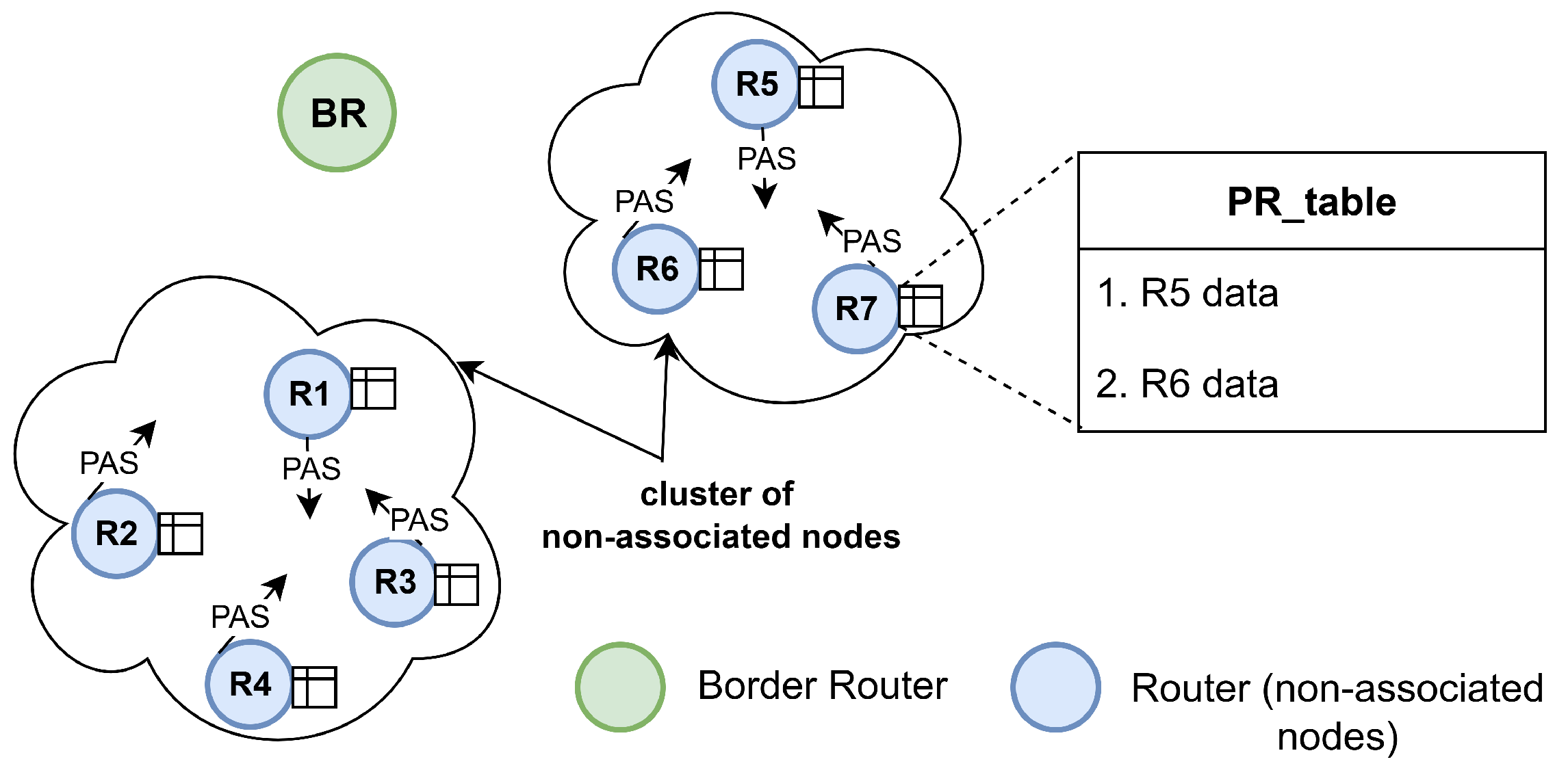
35], can enable rapid dissemination of PAN Advertisement (PA) packets within a cluster. To the best of our knowledge, and based on the literature review, the use of clusters for unassociated nodes in the initial association process has not yet been explored in Wi-SUN FAN.
In Wi-SUN FAN, unassociated nodes actively transmit PAN Advertisement Solicit (PAS) packets for network discovery [
14,
36]. PR Wi-SUN FAN leverages these PAS packets to establish synchronized clusters during non-JS1 channel scanning, where nodes acquire minimal association parameters that facilitate the discovery of channel hopping schedules within the cluster. This mechanism accelerates the dissemination of PA packets within clusters, thereby accelerating JS1 processing and reducing energy consumption. To achieve this, the proposed method is implemented in the Contiki-NG operating system, extending the work of [
17]. Furthermore, the evaluation of the proposed method, including the entire process of connecting nodes, demonstrates that using PR contributes to reducing the time required to form the network. Our main contributions are as follows:
Stochastic modeling of association times, deriving expectations for node association in linear, fully connected, and mesh Wi-SUN FAN networks.
Design of a cooperative association method based on PAS packets to form synchronized clusters in JS1 (PR Wi-SUN FAN), supported by stochastic modeling, demonstrating how Parallel Rendezvous reduces association time during JS1 in Wi-SUN FAN.
Implementation, simulation, and evaluation of the Parallel Rendezvous method on Wi-SUN FAN in JS1 using Contiki-NG, showing that the proposed approach reduces both association time and energy consumption.
Next,
Section 2 provides the background of the Wi-SUN FAN standard, while
Section 3 presents a theoretical explanation of JS1 association.
Section 4 introduces PR Wi-SUN FAN and analyzes its behavior during the JS1 association process.
Section 5 describes the configurations of the studied scenarios.
Section 6 presents the results. Finally,
Section 7 concludes the paper.
2. Wi-SUN FAN: Background and Overview
Wi-SUN FAN is a standard based on the IEEE 2857-2021 [
14] specification, which defines protocols for the first four layers of the OSI model. The physical and data link layers are implemented using IEEE 802.15.4 [
7]; the network layer utilizes IPv6, ICMPv6, RPL, and 6LoWPAN; and the transport layer supports both UDP and TCP. Security mechanisms are based on IEEE 802.1X, IEEE 802.11i, and EAP-TLS protocols.
The Wi-SUN FAN network has a hierarchical topology. It is formed based on a directed acyclic graph (DAG) rooted at the BR, which acts as the main parent for nodes R and L. To join the network, nodes R and L go through five joining states before reaching the operational state, a procedure referred to as the node connection process. This work focuses specifically on JS1, as it is in this phase that the implementation of the described optimization proposal occurs. JS1 corresponds to the discovery and selection process, which follows a scheduling program for channel management, explained below.
2.1. Wi-SUN FAN Scheduling
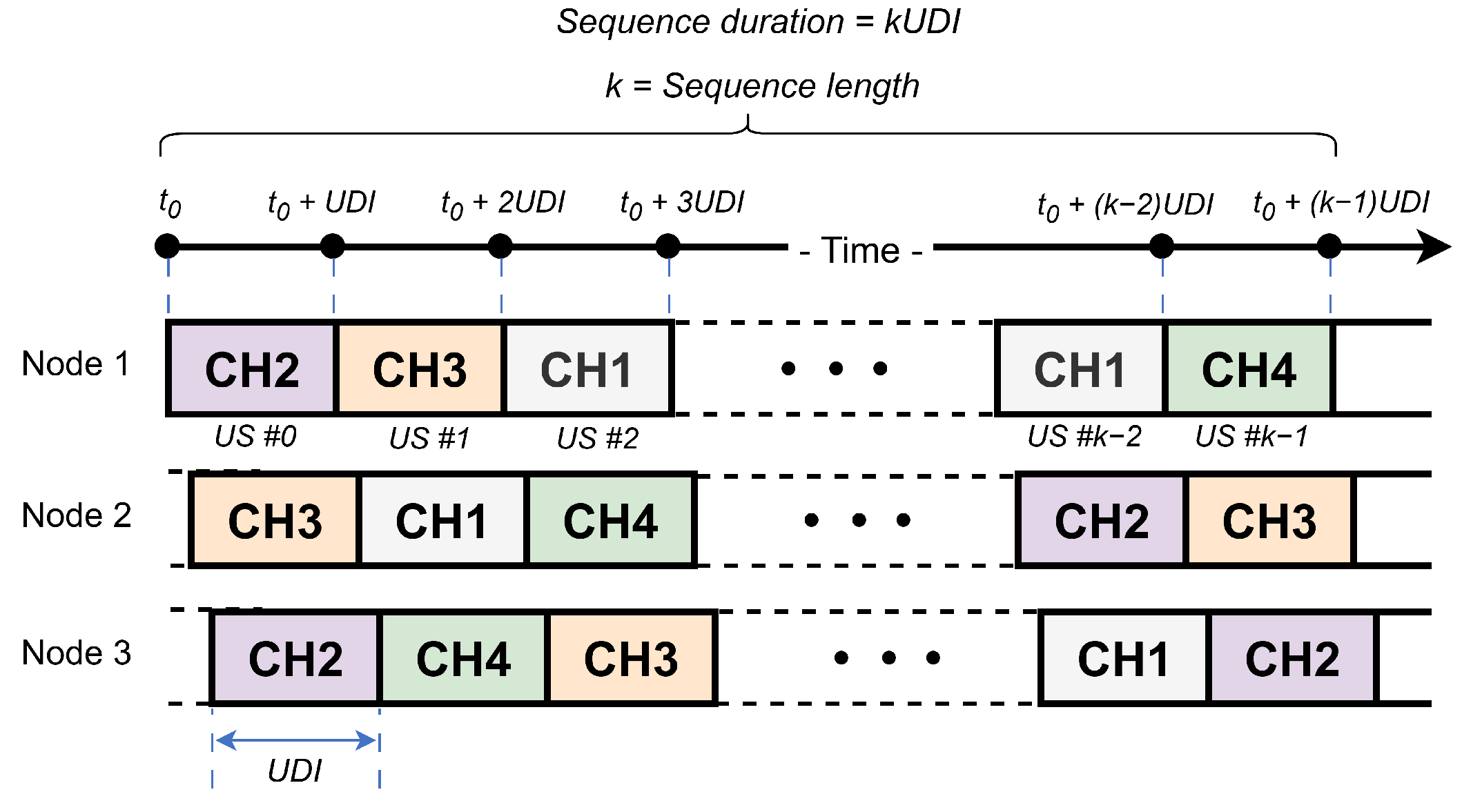
In Wi-SUN FAN networks, channel hopping scheduling methods are defined for both unicast and broadcast transmissions. This study focuses exclusively on unicast scheduling. In this scheme, time is divided into discrete slots, and the duration of a Unicast Slot (US) is termed the Unicast Dwell Interval (UDI). According to the standard, the UDI length is defined between 15 ms and 255 ms [
14]. Channel assignments are generated based on each node’s EUI-64 address, resulting in unique channel sequences for every node.
Figure 1 illustrates an example of unicast channel hopping for three nodes, with four available channels (CH1–CH4).
A channel function defines a pseudo-random sequence used for channel hopping scheduling. It establishes a method for determining, from the list of available physical channels, the specific channel on which a node operates at any given time. Several channel functions are supported at the link layer for unicast operation, including fixed channel, TR51CH, DH1CF, and vendor-defined.
Since each node generates its own unicast schedule, transmitting a frame to a neighbor requires calculating the frequency channel on which the neighbor is currently listening. The transmission must then occur on that channel. To determine the current position in a node’s channel hopping sequence, both the transmitter and receiver must use the same predefined function, which relies on the node’s EUI-64 address, channel number, and Unicast Slot (US) number. To perform the discovery process over this channel schedule, Wi-SUN FAN uses an active scanning method.
2.2. Active Scan in Wi-SUN FAN
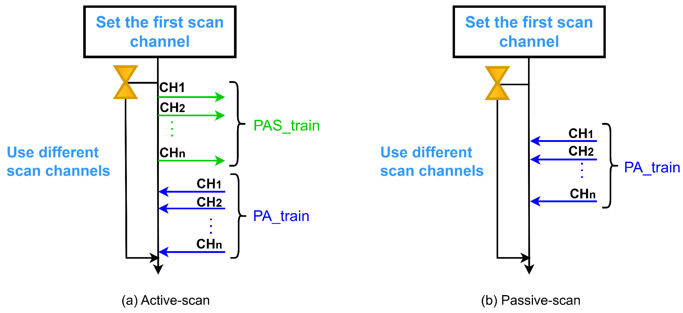
Wi-SUN FAN networks utilize an active scanning method for node discovery and association. In this mode, a node seeking to join a network initiates the process by transmitting PAS packets to request and accelerate PA transmissions from advertising nodes within the PAN. This contrasts with passive scanning, where a node scans channels without sending requests until it receives a PA packet. For node R, passive scanning is consistently performed following a transmission, whereas node L enters a sleep mode to conserve energy.
The active scanning mechanism involves sending multiple PAS packets sequentially across each available physical channel (CH1, CH2, …, CH
n)—termed
in this work. Upon receiving a PAS packet, an advertising node accelerates PA transmissions, also following a sequential channel order (denoted
).
Figure 2 illustrates this active scanning process alongside a passive scanning comparison.
During the discovery and joining process in JS1, Wi-SUN FAN employs the MLME-WS-ASYNC-FRAME service [
14], a primitive mechanism that manages asynchronous transmission of PA and PAS trains.
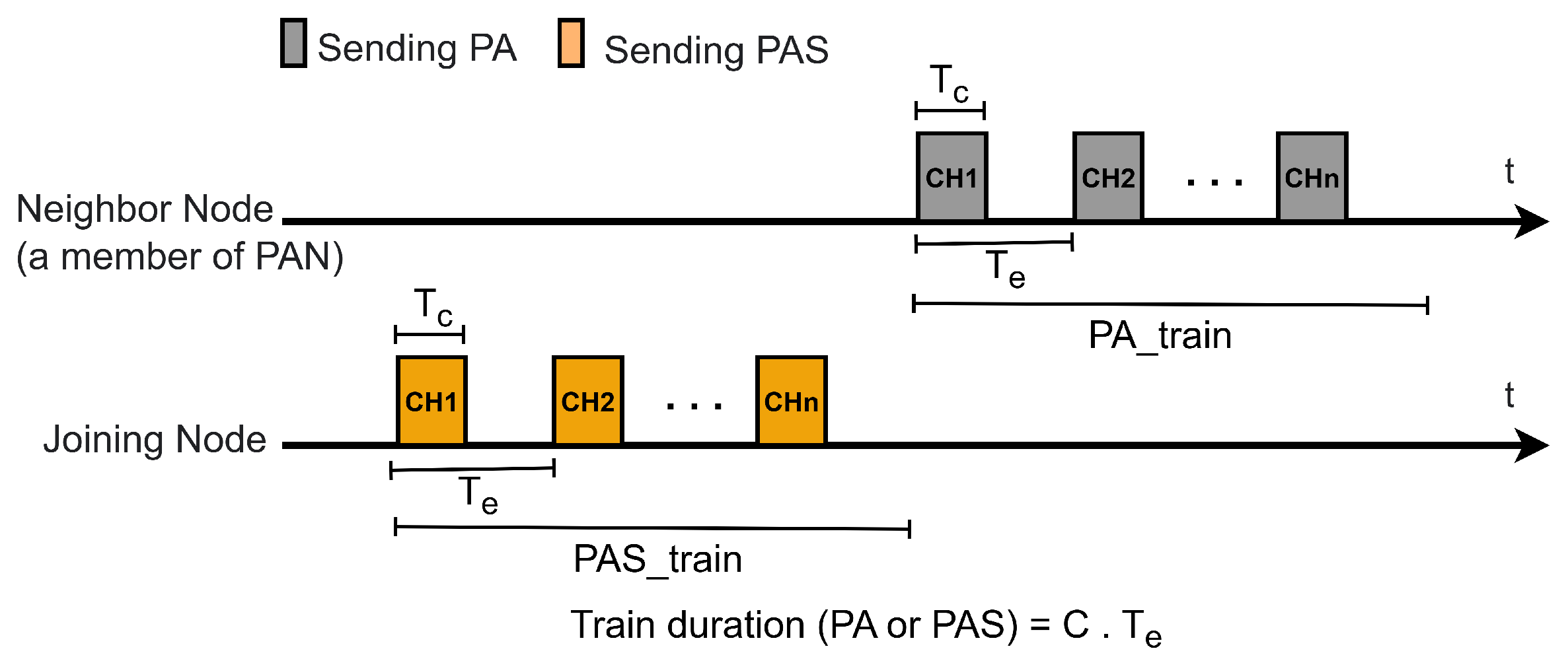
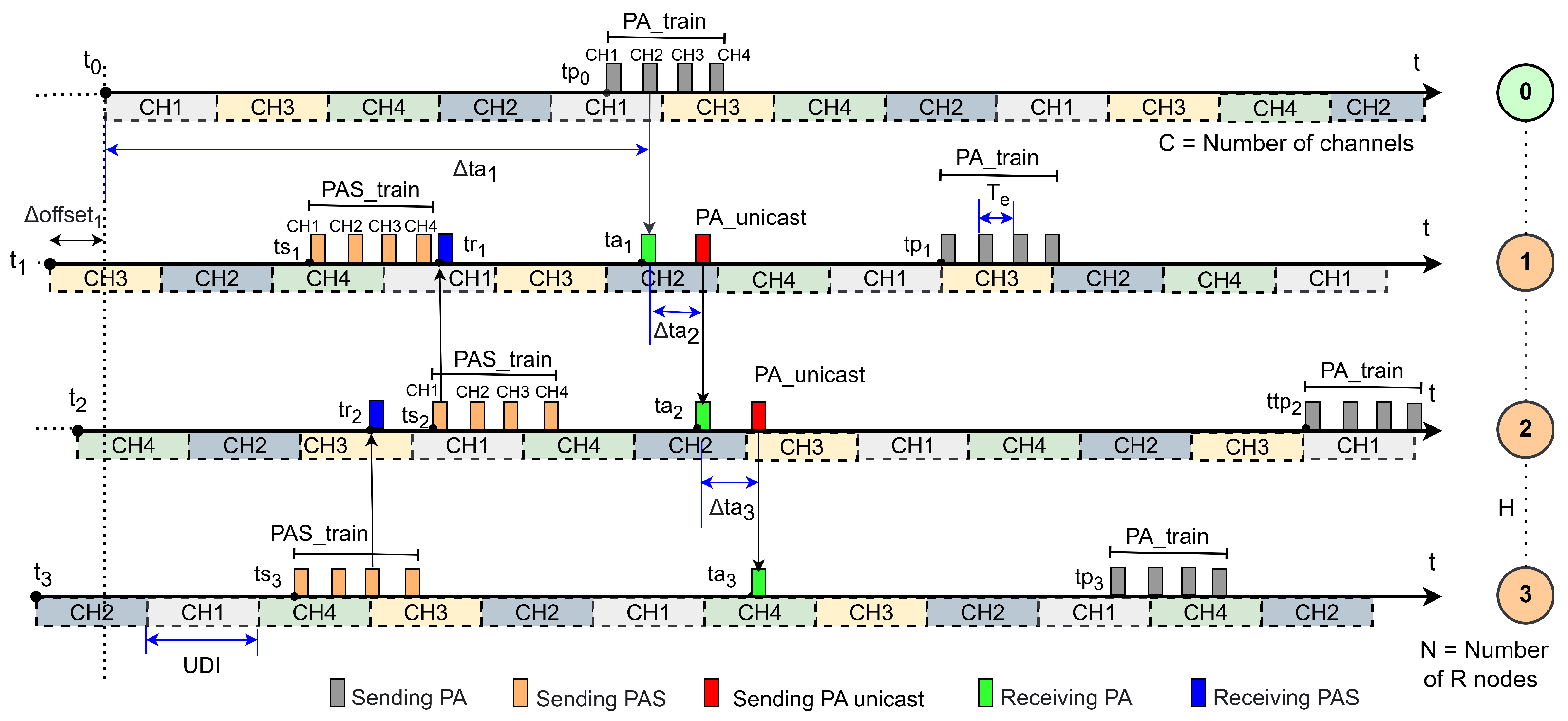
Figure 3 illustrates these transmissions, which must span all available channels. A
or
is characterized by the packet duration
, the interval between consecutive packet transmissions
, and the total train duration, expressed as
, where
C denotes the number of available channels.
The MLME-WS-ASYNC-FRAME mechanism triggers PA or PAS packet transmission when the trickle timer requires a transmission.
2.3. Application of Trickle Timer on Wi-SUN FAN
A Wi-SUN FAN junction node must maintain the trickle timer to control the transmission frequency of PAS and PA packets in the JS1 and JS5 processes, respectively. The operation of the trickle timer is described in the RFC6206 documentation [
18], where the algorithm is configured with three parameters:
, the minimum interval, defined in time units such as milliseconds or seconds;
, the maximum interval, calculated by successively doubling
a specified number of times; and
k, the redundancy constant, which limits the number of allowed transmissions to avoid redundant messages.
Figure 4 illustrates the initial behavior of the trickle timer, which starts by resetting the consistency counter
c to zero. Next, the interval length
I is randomly selected within the range
, and the transmission time
t is chosen uniformly within the subinterval
[
37]. In the context of Wi-SUN FAN, time
t denotes the scheduled start time of the PA and PAS trains, as detailed in
Section 2.2. When a node receives identical information from its neighbors, it increments the counter
c. Transmission at time
t only occurs if
c is less than the redundancy constant
k; otherwise, the transmission is suppressed. At the end of each interval
I, the algorithm doubles its duration up to the maximum interval defined by
. If the current interval has not yet expired,
c is reset to zero and
t is randomly selected from the range
. A relevant aspect of the trickle timer’s operation is the listen-only period, which corresponds to the first half of each interval. This structure divides the interval into two different phases: a listen-only phase and a transmit phase during which transmissions can occur. The behavior of the trickle timer is described in six steps in the RFC6206 documentation [
18].
In addition, the trickle timer uses the concepts of consistent, inconsistent, and generic events to suppress unnecessary messages and to adapt the scheduling of maintenance packets. This enables the trickle timer to be adapted and adopted by various protocols that interpret these events according to their specific semantics. In Wi-SUN FAN, the transmission of PAS and PA packets incorporates these considerations, as described in the standard documentation [
14], which relate to starting, restarting, or stopping the timer.
The Wi-SUN FAN standard also provides recommendations for trickle timer configuration according to network size, differentiating between small-scale networks with tens of nodes per PAN (
s and
s), which use shorter intervals to prioritize responsiveness, and large-scale networks with thousands of nodes per PAN (
s and
min), which use longer intervals to minimize congestion and optimize scalability [
14].
3. Stochastic Modeling of JS1-Based Discovery in Wi-SUN FAN
In Wi-SUN FAN networks, a node in JS1 initiates discovery by performing a channel scan () to detect PA packets across available channels. This scan follows a sequential order defined by the channel array V, which is calculated using a channel function in a round-robin manner. For this study, we implement an approach where the connection process transitions directly from JS1 to JS5 under version 1.0 of the standard. By bypassing intermediate joining states, nodes operate exclusively within JS1, enabling focused analysis of this specific phase.
Algorithm 1 describes the Wi-SUN FAN joining process for nodes in JS1. The process begins by defining the number of channels (C), essential for channel hopping (line 1). A channel function then generates a pseudo-random sequence based on the node’s EUI-64 address, stored in array (line 2). The channel index () selects the current channel within (line 3), while the Unicast Dwell Interval () determines the listening duration per channel before switching (line 4). is initialized to 0 (line 5), initiating the scan at the first channel in . The node enters JS1 (line 6), the initial connection state. Here, the trickle timer for PAS packets activates (line 7), and the node scans the channel (line 8), following the generated sequence.
After initial configuration, the node enters a continuous loop during network connection (line 9). The loop first checks for UDI timer expiration; if expired, it restarts the UDI timer, increments
, and advances to the next channel in
(lines 10–14). While unassociated and in JS1, if the trickle timer permits PAS transmission, the node sends PAS to request PA packets (lines 15–17). Upon receiving PA, it stops the PAS trickle timer and transitions to JS5 (lines 18–22). In JS5 (associated state), the node starts the PA trickle timer to announce its presence to its neighbors, facilitating network formation (lines 23–26). Throughout, it continuously monitors its join state and scans channels per
(line 27).
| Algorithm 1 Wi-SUN FAN discovery process on JS1 |
- 1:
C: number of available channels - 2:
← channel_function() - 3:
: channel index - 4:
: unicast dwell interval - 5:
← 0 - 6:
node = JS1 - 7:
start of PAS trickle timer - 8:
- 9:
while node is in the process of connecting do - 10:
if timer has expired then - 11:
resets the scan time - 12:
- 13:
- 14:
end if - 15:
if node = JS1 then - 16:
node is not associated - 17:
transmits PAS when the trickle timer allows - 18:
if PA is received then - 19:
stop of PAS trickle timer - 20:
node ← JS5 - 21:
end if - 22:
end if - 23:
if node = JS5 then - 24:
node is associated - 25:
start of PA trickle timer - 26:
end if - 27:
end while
|
The Extensive Authentication Protocol over LAN (EAPoL) candidate list was not implemented in JS1. This EAPoL candidate list is used to determine the PAN to which the node will attempt to connect, based on the lowest route cost, which mainly depends on information obtained in JS4. Therefore, the node selects only the first PA received to advance to JS5. This choice aims to reduce the complexity of the implementation and allow for a more controlled study by isolating JS1.
Based on these considerations, a theoretical analysis will be carried out following the modeling presented in [
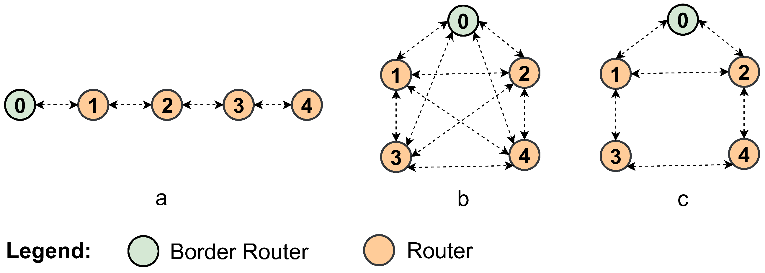
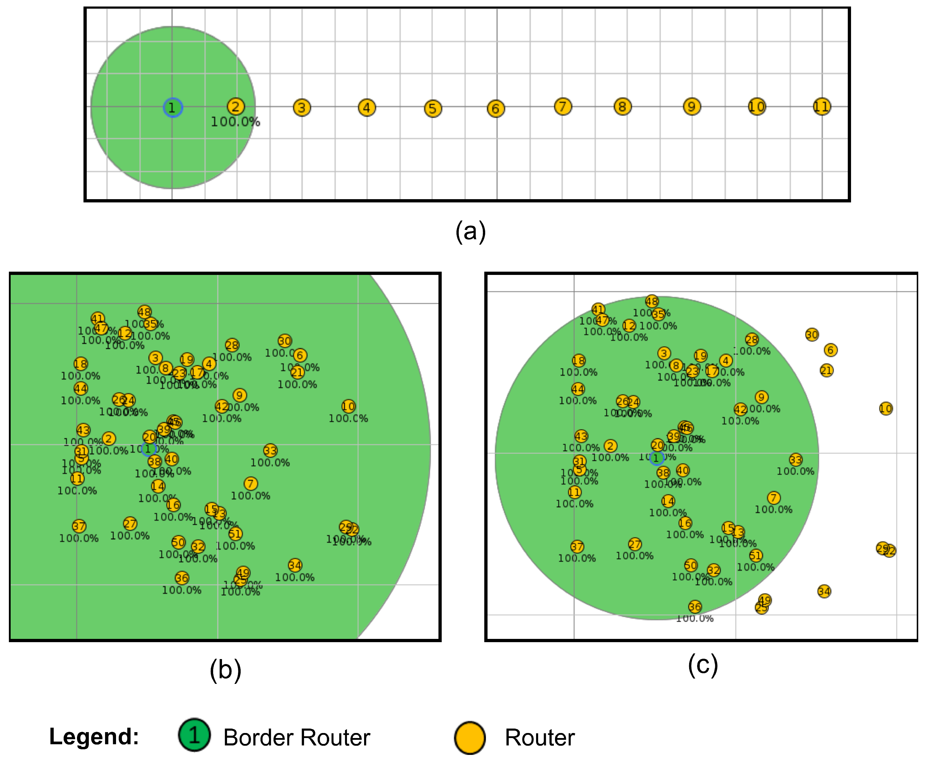
34], considering three network topologies—linear, fully connected, and mesh—as shown in
Figure 5.
3.1. Linear Network in JS1—Wi-SUN FAN
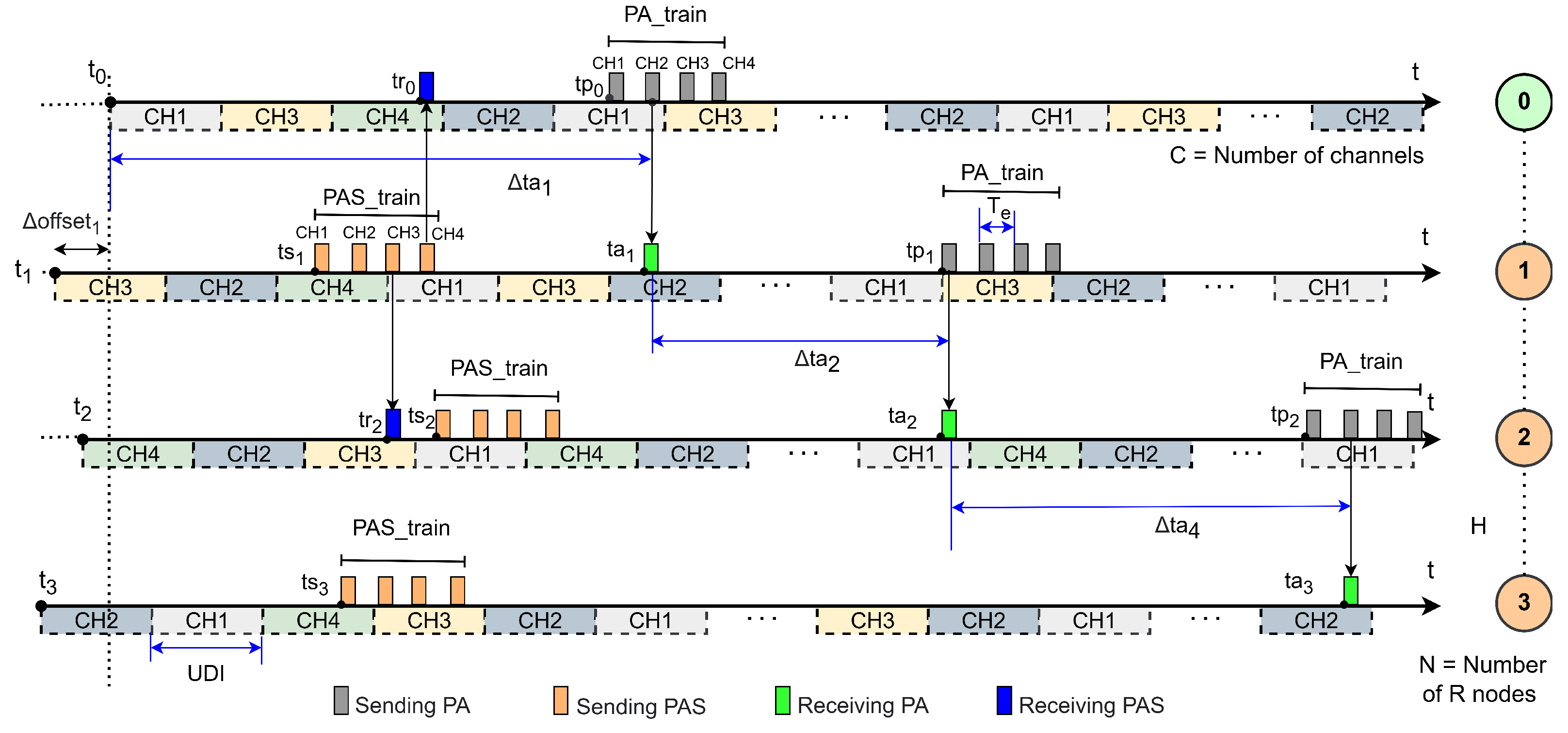
Figure 6 depicts a packet exchange and association process in a linear network topology comprising a BR (node 0, initially associated) and
R nodes (nodes 1–3) attempting to join. This worst-case scenario (
Figure 5a) has a network diameter
hops and
C available channels. Node 0 is connected at
. During association, node
j (
to
N) listens to PA packets from node
and PAS packets from non-associated node
, except node
N, which only hears PA packets from node
. Association requires sequential dependency: node
j connects only after node
.
Figure 6 shows this timeline, where node
N’s connection depends on node
’s prior association.
For each node, a sequence of channels is shown as dotted horizontal bars, with the sequence length determined by the number of channels (C). Transmissions of and are represented by gray and orange vertical bars, respectively, while receptions of PA and PAS packets are indicated by green and blue vertical bars, respectively.
In this context, node 0 (distinct from other nodes) initiates network formation at . To measure the linear network’s formation time, the time offsets () of each router node are disregarded. This alignment ensures all measurements are referenced to the Border Router’s start time.
An important point is the disregard, in our calculation, of the reception of PAS packets at time for the case of an associated node, since this does not affect the start of the time of the first at time . This situation generates an inconsistency in the trickle timer that resets the interval for . However, this has no impact, since the interval already uses . Furthermore, in the case of PAS reception in non-associated nodes, we can also disregard the generation of a consistency in the trickle timer, which suppresses the sending of the , which is not considered for our calculation.
The time required for node
j to associate with the Wi-SUN FAN network is represented by
, which is the time elapsed from the moment node
associates until the moment node
j hears a PA from node
. This can be represented as
Since
, the value of
is also 0, resulting in
. This corresponds to the time interval between the association of node 0 and the reception of the PA by node 1, and it is therefore equal to the association time of node 1. The instant
can be expressed as the sum of the start of the
, denoted by
, and the delay
until node 1 receives one of the
packets:
The value of
is determined by the interval specified in the trickle timer, which follows a continuous uniform distribution [
37] over the interval
. Therefore, the expected value of the start of
is
.
Let
be the time between the start of the
and the instant at which a PA packet is received by node 1, assuming that at least one packet will be received, in a guaranteed reception scenario occurring at most within
time units, where
C denotes the number of available channels, and
is the interval between consecutive packets of the
. Assuming that the start of the hop of node 1 is uniformly distributed over the cycle of
C channel, then
with
. Consequently, the expected value of
is given by
Considering that node
does not start sending a
until it has joined the network, this implies that the elapsed time between a node joining and the PA being sent to the next node is the same for all nodes in the network. This assumption is reasonable because, in the context of the Wi-SUN FAN algorithm, the behavior of nodes is sequential in a linear network. Therefore, the expected value of the time between node association, denoted as
in this analysis, can be assumed to be the same for all nodes in the network, i.e.,:
Using (
4) and rewriting (
1) in a convenient form, we have
From this, by solving a linear recurrence equation, the expected value of the time to form a linear network of diameter
, denoted as
, can be expressed as
3.2. Fully-Connected Network in JS1—Wi-SUN FAN
In a fully connected network, all nodes can transmit and receive directly to and from any other nodes in the network. This means that there are no restrictions on direct communication between nodes, allowing for full connectivity, as shown in
Figure 5b. In this scenario, when an unassociated node attempts to join the network, it can join through any of its neighbors that are already joined.
Let
be the time required for node
j to hear a PA packet sent by node
i. Based on this definition, the association time
in a network with
N nodes trying to associate can be expressed as
where
indicates that node
j selects the shortest PA packet reception time among all nodes
i. Now, considering the last node to join the network,
, from (
7), the expected time to form a network of
N unassociated nodes into a fully connected network can be expressed by the association time of the last node:
Considering an ideal scenario and ignoring potential issues that could interfere with the reception of PAs by the nodes, it is possible to establish a maximum limit for the time node l would take to receive a PA from the BR (). This maximum limit is determined by the trickle timer and the . Assuming that this limit exists, the maximum time for node l to receive a PA from the BR is defined as , and we have ≤ , where , with I being the interval defined by the trickle timer, C the maximum number of available channels, and the interval time between PAs in the .
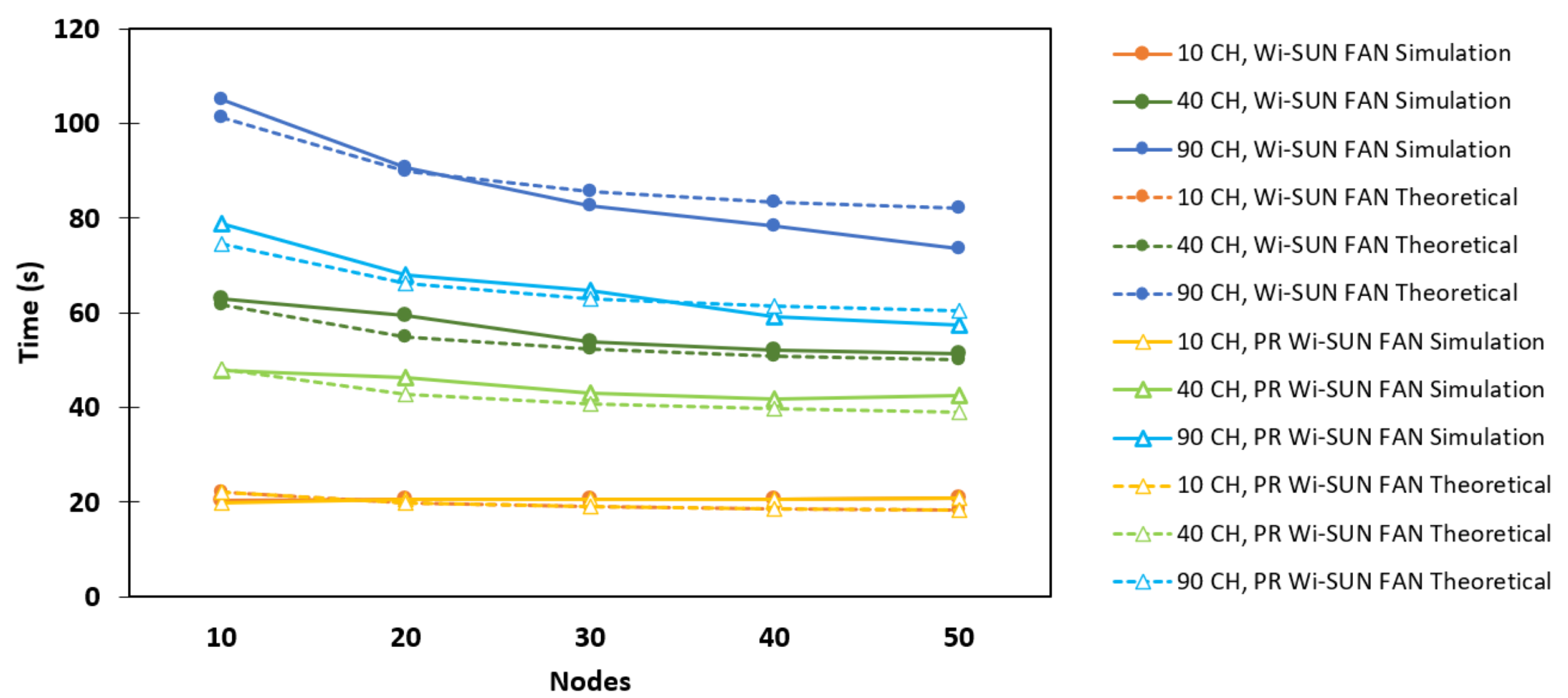
In a fully connected network, unlike in a linear network, the expected time to form the network,
, does not increase linearly with the number of nodes; instead, the expected value decreases as the number of nodes increases. That is, the value calculated by Equation (
8) tends to decrease as the number of elements in
increases. This behavior is discussed in
Section 4 in the context of the PR Wi-SUN FAN fully connected network.
3.3. Mesh Network in JS1—Wi-SUN FAN
In a mesh network, illustrated in
Figure 5c, nodes can have more than two neighbors, meaning that each node in the network can be connected to multiple other nodes. However, it is important to note that despite having multiple neighbors, a node in a mesh network can neither transmit to nor receive from any node other than its direct neighbors. For example, in
Figure 5c, node 3 can only associate with the network through nodes 1 and 4, depending on which node hears a PA first.
For a node in a mesh network, let
be the set containing the specific nodes that are within the direct communication range of that node and can send PAs to it. Given this set, (
7) can be rewritten as
and the expected time to connect the entire network can be expressed as
Since the number of elements in
is smaller than
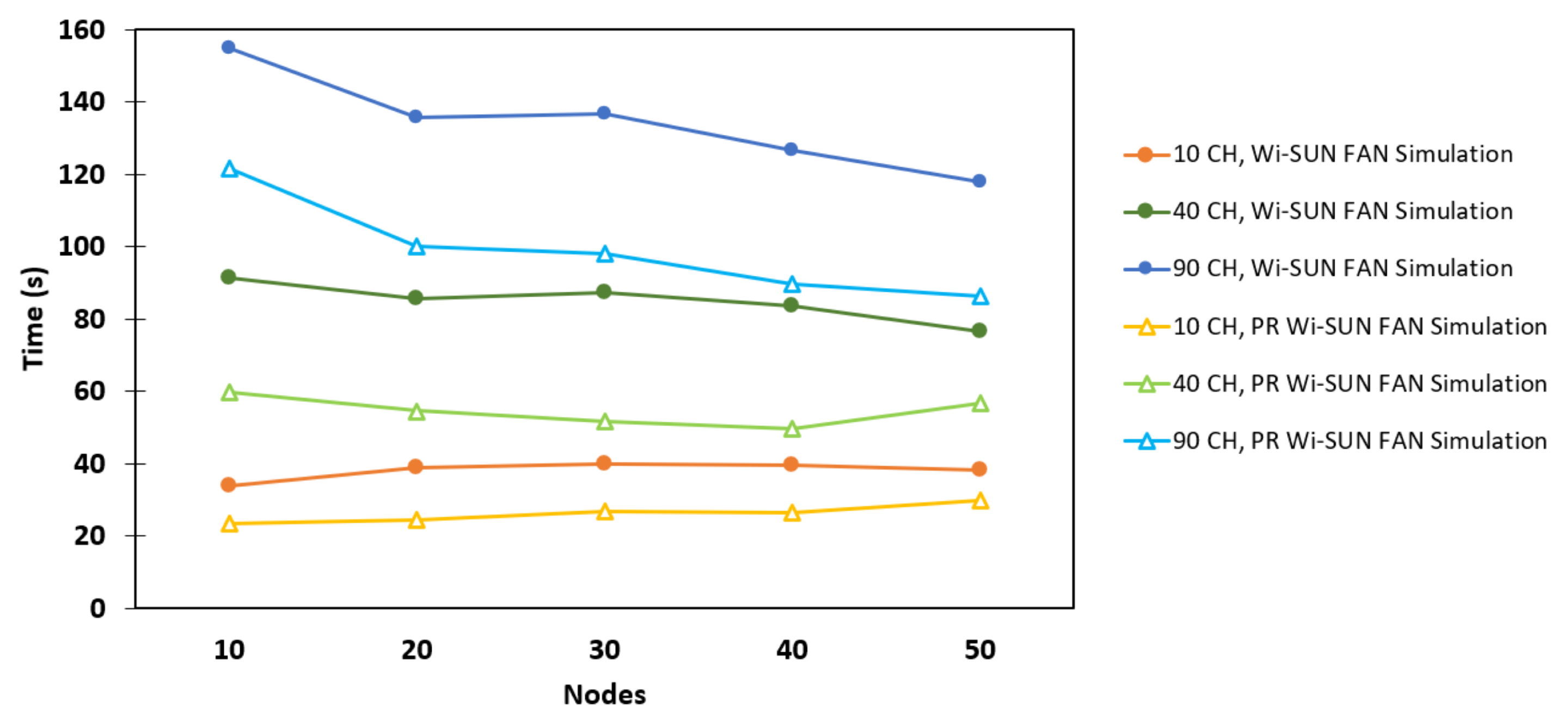
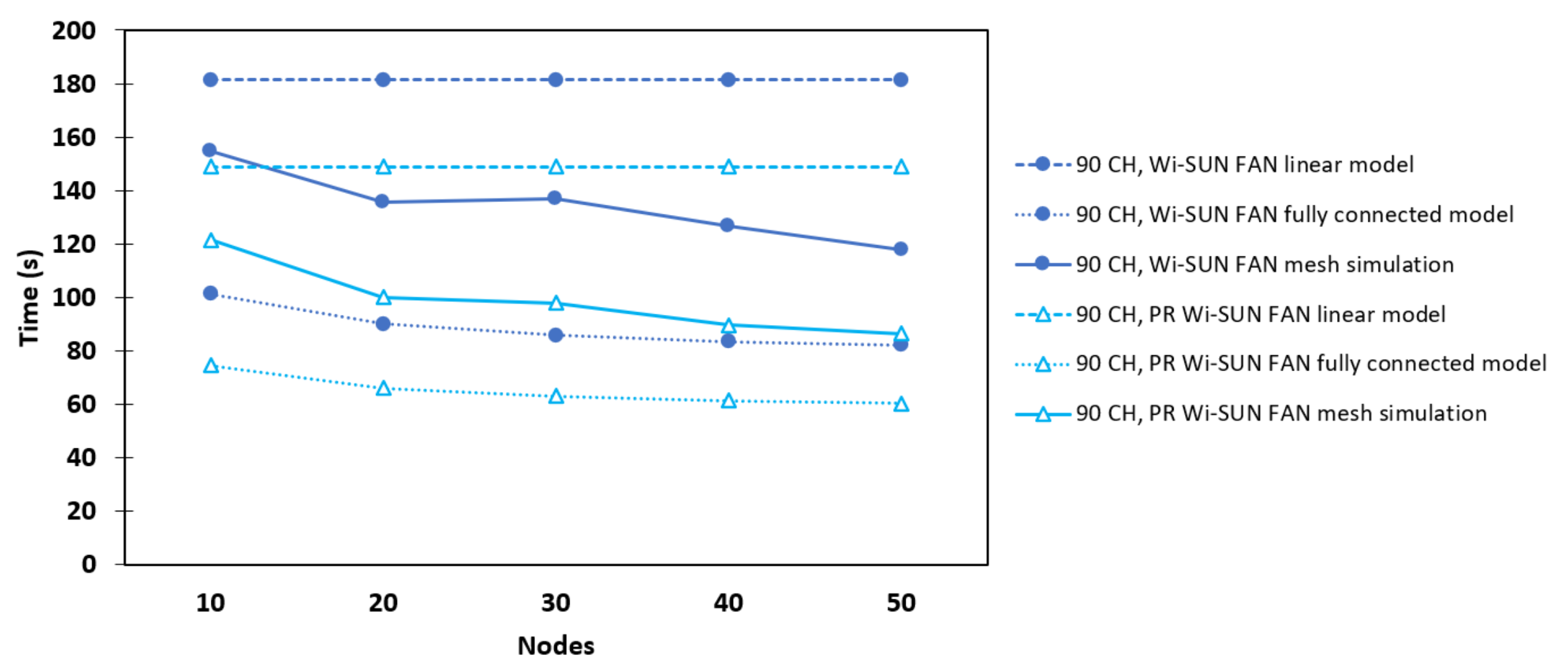
N, the expected time to form a mesh network is greater than that of a fully connected network with the same number of nodes. Furthermore, the network diameter impacts the result of Equation (
10), but since the diameter
H is smaller than the number of nodes
N, it becomes evident that
is upper-bounded by Equation (
6). That is, we should expect
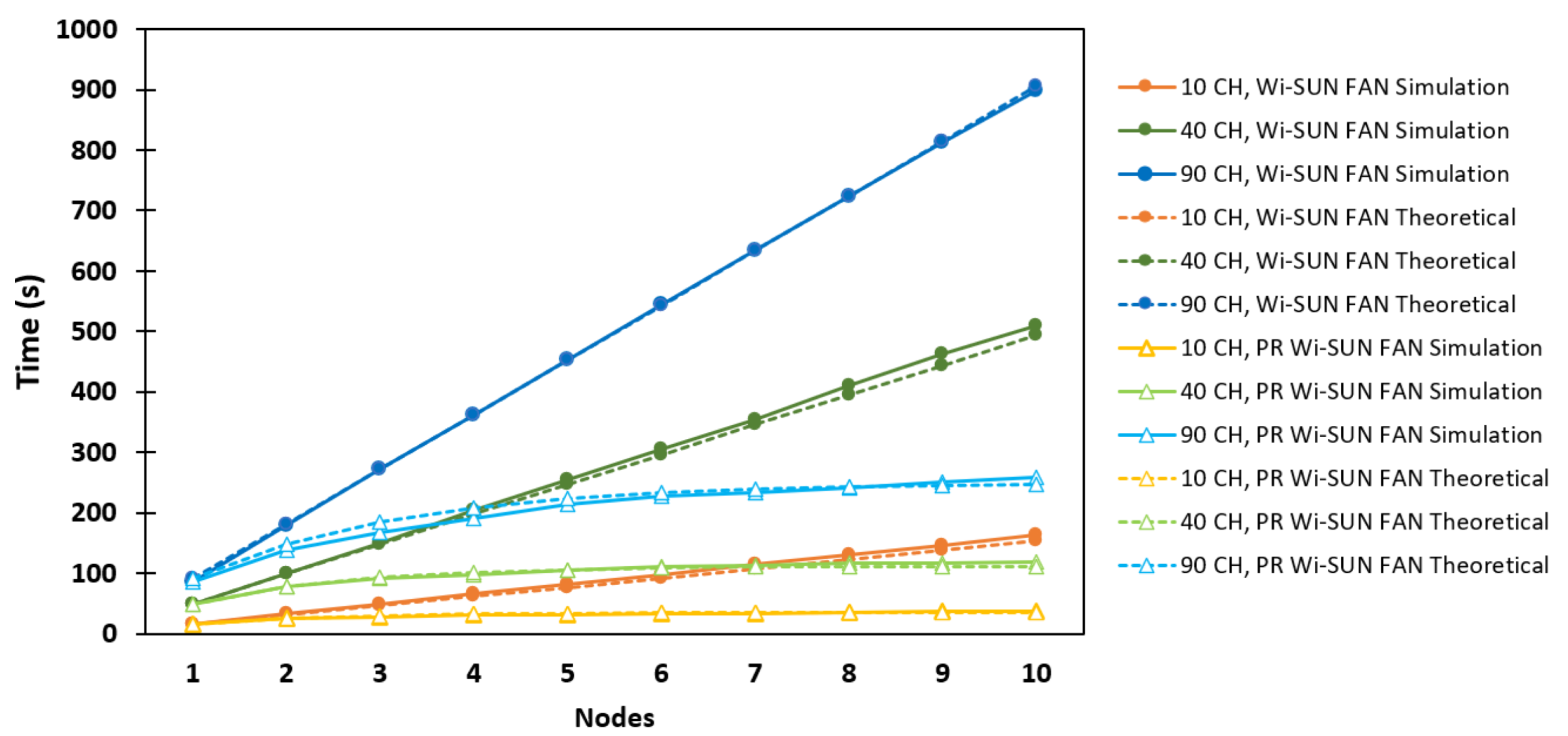
for a mesh network to lie somewhere between the values obtained for a fully connected network and a linear network. This intuitive interpretation is corroborated by the results presented in
Section 6.
5. Experimental Setup
To evaluate the performance of our proposal, a comparison was made between Wi-SUN FAN and PR Wi-SUN FAN in JS1. The Contiki-NG operating system was used, following the approach described in [
17] to implement Algorithms 1 and 2 of our proposal. Using the Cooja tool from Contiki-NG, several simulations were carried out with BR and R nodes, running on the native Cooja mote [
17]. A configuration operating in the Sub-GHz band was used, offering 90 channels and a data rate of 50 kbps in the simulator.
To reflect the asynchronous nature of Wi-SUN FAN networks [
38], three topologies were generated: linear, fully connected, and mesh. In each topology, multiple simulations were conducted by varying the activation times of the nodes through the “random seed” parameter, thereby replicating the conditions of a fixed utility service network. In all simulations, R nodes start disconnected, meaning they start from JS1. In every scenario, one BR was deployed, while the remaining N nodes were of type R. In the linear topology, 10 R nodes were deployed, each attempting to associate. In the fully connected and mesh topologies, 10 to 50 R nodes were deployed, also attempting to associate. For the
size, a maximum capacity of 50 neighbors was configured.
Channel scanning performance critically depends on the frequency of PA and PAS packet transmissions; however, since the standard does not specify the interval
for these transmissions and mandates that the UDI length remain within a defined range, multiple configurations were implemented for our selected channel function. This function generates a pseudorandom sequence whose length matches the number of channels, thereby simplifying the analysis. These configurations involve the parameters
and
.
Table 1 presents the configurations used for different numbers of channels in the implemented topologies.
These configurations ensure that PA or PAS packets are transmitted at least once across the entire pseudo-random sequence, which operates according to a round-robin cyclical schedule.
To configure the trickle timer at the beginning of the PA or PAS packet train transmission, the following parameters were used:
s,
s, and
, for both Wi-SUN FAN and PR Wi-SUN FAN, in a small-scale configuration [
14]. The only variation occurred in the linear topology of PR Wi-SUN FAN, where
was used in order to redundantly transmit PAS packets and prevent them from being quickly suppressed [
18]. This configuration aims to increase the effectiveness of storing the information of the sole neighbor in the
.
The performance of Algorithms 1 and 2 is evaluated in terms of the average time required to form a network with
nodes, including the BR and the R nodes, during network formation in JS1. To obtain the data, 100 simulations were conducted for each number of channels. The topologies were constructed using Cooja.
Figure 9 illustrates the topologies built for the maximum number of nodes used in this study.
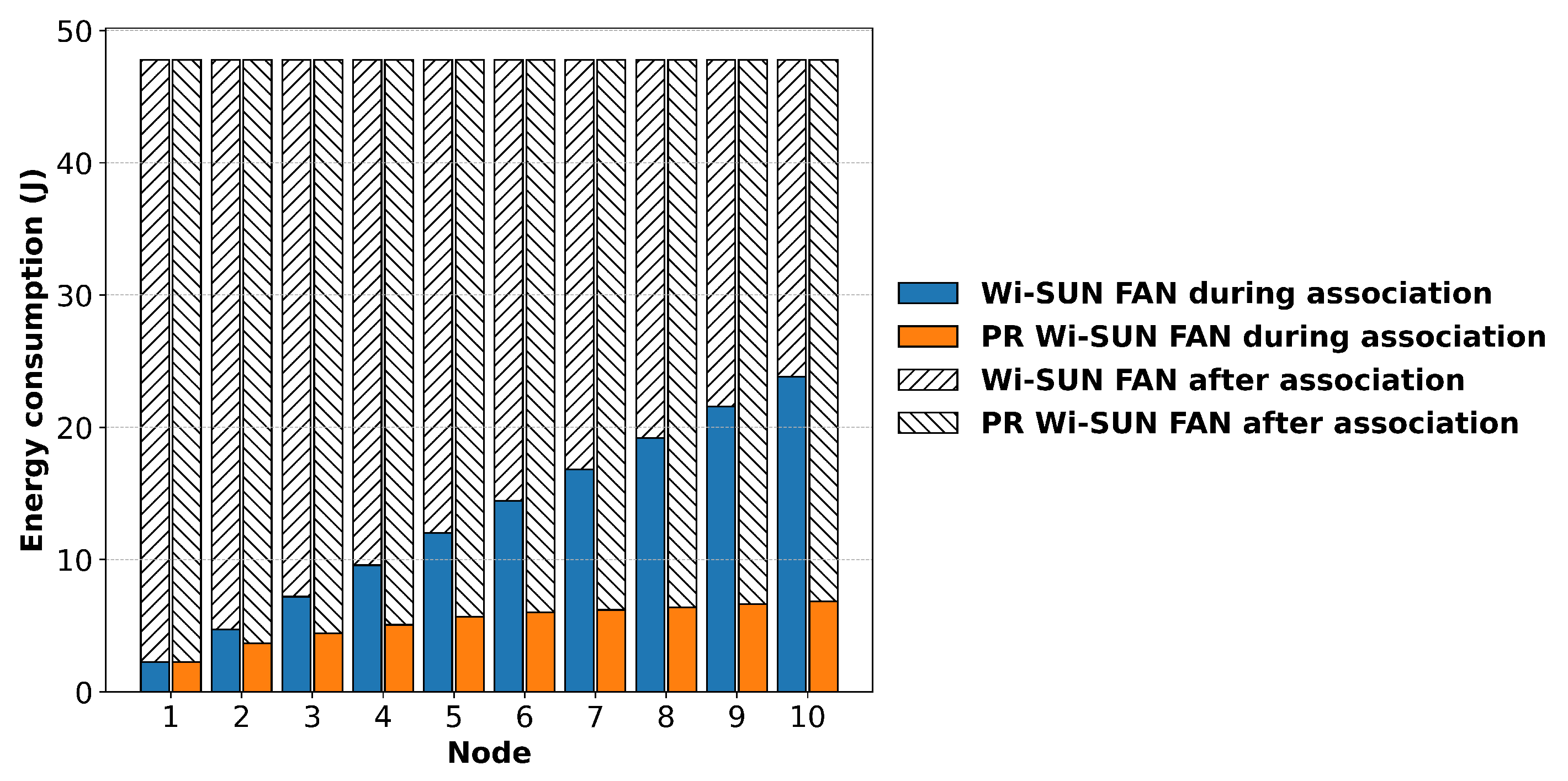
Energy Consumption
In terms of power consumption, both the BR and R nodes in Wi-SUN FAN keep their radio interfaces continuously on during the association and operation processes. For R nodes specifically, this is necessary to enable communication from other nodes positioned below them, as children. Due to their role within the Wi-SUN FAN network, R nodes are not expected to implement sleep slots, which are a common power-saving mechanism.
To estimate energy consumption, the linear network topology shown in
Figure 9a is used. Energy consumption is measured at the end of each R node’s association time (
). Therefore, the total energy consumption in JS1 of node
j,
, can be represented as
where
is the power consumed by the node with the radio on during the association phases.
BR and R nodes alternate between two modes: transmission (Tx) and reception (Rx). To estimate, for example, the value of , the power consumption in Tx and Rx modes is summed. This is calculated by multiplying the supply voltage by the current consumed in each node. For our analysis in this work, we used the following specifications for the CC1352P7 as an example: the current in Tx mode is 8 mA, in Rx mode it is 5.4 mA, and for the CPU it is 2.63 mA, with an operating voltage of 3.3 V. This results in a power consumption of approximately 52.9 mW (or 52.9 mJ/s).
