Abstract
Accurate docking of Autonomous Guided Vehicles (AGVs) is a critical requirement for efficient automated production systems in Industry 4.0, particularly for collaborative tasks with robotic arms that have a limited working range. This paper introduces a cost-effective software-upgrade solution to enhance the precision of the final docking phase without requiring new hardware. Our approach is based on a two-stage strategy: first, a switch from a global dead reckoning system to a local navigation scheme, is triggered near the docking station; second, a dedicated Takagi-Sugeno Fuzzy Logic Controller (FLC), guides the AGV to its final position with high accuracy. The core novelty of our FLC is its implementation as a gain-scheduling lookup table (LUT), which synthesizes critical state variables—heading error and distance error—from limited proximity sensor data, to robustly handle positional uncertainty and environmental variations. This method directly addresses the inadequacies of traditional odometry, whose cumulative errors become unacceptable at the critical docking point. For experimental validation, we assume the global navigation delivers the AGV to a general switching point, near the assembly station with an unknown true pose. We detail the design of the fuzzy controller and present experimental results that demonstrate a significant improvement, achieving repeatable docking accuracy within industrially acceptable tolerances.
1. Introduction
Autonomous Guided Vehicles (AGVs) [1] represent a significant application of autonomous technology, with wide utility across various sectors [2] such as manufacturing [3], agriculture, defense, and services [4]. AGVs have become a transformative force in the transportation industry [5], offering potential benefits in terms of safety, efficiency, and environmental impact. However, operating in complex environments presents challenges that necessitate the use of advanced algorithms for navigation, object detection, and decision-making.
Current systems enable AGVs to navigate safely and efficiently within production halls. Yet, achieving the necessary precision for docking operations is a critical challenge. Ensuring safety within industrial environments [6,7] and for the workers is crucial. Additionally, precise docking is vital, as emphasized in recent studies [8], for the successful execution of subsequent production processes [9], which often involve robots or collaborative robots [10].
The docking procedure [11] for an AGV presents unique challenges and requires specialized algorithms. Various sensor technologies have been applied: LiDAR for environment mapping [12], ultrasonic sensors for short-range distance measurement [13], radar for robust motion tracking [14], IMUs for orientation estimation [15], and wheel detectors [16]. These sensors facilitate environmental mapping and enhance positional accuracy [17], often through data fusion techniques [18] and the simultaneous localization and mapping (SLAM) method [19]. They also improve the precision [20] of local navigation [21] and autonomous driving of the AGV.
This research is motivated by a critical industrial constraint: the widespread deployment of existing AGV navigation systems, which are costly and logistically prohibitive to replace outright. Consequently, any enhancement must minimize hardware changes, ruling out solutions based on cameras or LiDAR [22]. The only industrially acceptable approach was a software update supplemented by low-cost proximity sensors. To address this, we developed a novel strategy where the AGV switches to a local navigation procedure upon approaching an assembly station (AS), leveraging a two-step fuzzy logic system to interpret the new sensor data [23]. This symbiosis of limited hardware change and intelligent software constitutes the core novelty of our work.
This research focuses on the analysis and implementation of an autonomous docking algorithm while approaches the AS. Docking, in this case, means stopping AGV at a particular position [24] with acceptable accuracy to cooperate with robotic arm. Therefore, an efficient local navigation algorithm is crucial for the effective operation of AGVs. The analysis covers the integration of sensor data [25], the interpretation of environmental cues, and the generation of control commands. The primary objective of the research was to develop a robust local docking algorithm that ensures a safe and efficient path [26] for the AGV to achieve accurate docking from its switching position [27] (Figure 1).
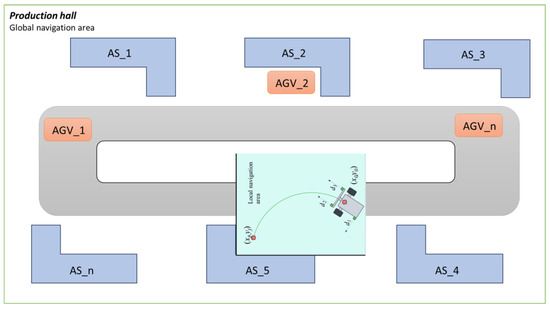
Figure 1.
Production hall with exemplary assembly stations (global navigation area).
The novelty of the proposed solution arises from the navigation scheme, where switching between global and local navigation is mandatory, the use of low-cost range finders (time-of-flight, TOF), and a fuzzy logic controller with gain scheduler to navigate toward the docking point and stop at the final position. This solution can be implemented in hardware with only a software update. The approach aims to reach the docking point with accuracy better than that of the current dead reckoning algorithm. The efficiency of the developed method was validated through experiments conducted with an AGV system and compared to the traditional dead reckoning algorithm. These experiments were designed to assess the accuracy and reliability of the AGV’s positioning during docking maneuvers, which are critical for applications such as automated warehouses and manufacturing environments.
The paper is organized as follows: the second section presents the general concept of switching between global and local navigation, the third section describes the physical architecture of the AGV, the fourth section presents the Fuzzy Logic method developed for docking functionality, the fifth section presents currently implemented docking method, the sixth section details the docking experiments conducted and the last presents general conclusions.
1.1. Switching to Local Navigation–Docking Procedure
It is important to note that this problem of docking inaccuracy is not merely a function of the navigation system’s design, but also of its interaction with the operational environment. Even if a global navigation system’s theoretical accuracy and implementation cost are deemed acceptable, its final performance is compromised by unpredictable factors such as floor surface quality, load distribution, and tire wear. These variables introduce errors that are systematic yet non-repeatable, making them difficult to model and correct through calibration alone. Therefore, a solution is required that can adapt to these changing conditions in real-time, specifically during the critical final approach.
In a conventional implementation, the global navigation system often facilitates one-way transportation of loads by AGVs to Automated Storage (AS) throughout the production hall. However, this system allows the AGV to reach the designated AS only with limited precision. Since AGVs frequently transport loads of varying weights and sizes, which may also be loaded asymmetrically, this affects the pressure distribution on each wheel. Consequently, it can lead to errors in odometry, resulting in inaccurate measurements of the distance traveled by the AGV. This precision deficit becomes a critical failure point in systems where AGVs are integrated with collaborative robots (cobots) designed to assist human operators at the AS. The cobot’s operational range is finite and predicated on the AGV docking in an exact position and orientation. Precise alignment ensures the robotic arm has its full, optimal working envelope. Imprecise docking, however, severely constricts this range. This not only hinders functionality but fundamentally compromises safety—the cornerstone of human–robot interaction. A mis-docked AGV may violate the pre-defined collaborative workspace, forcing an unsafe intervention, a work stoppage, or a time-consuming and inefficient manual redocking procedure, nullifying the benefits of automation.
For this reason, when an AGV approaches a designated AS using global navigation (odometry), it becomes necessary to switch to local navigation. The local navigation system enables the AGV to travel to the docking point, for example, based on distance measurements to the shape of the specific AS. In the case of the AGV docking system studied as part of the CoBotAGV project, it was assumed that the side walls of the AS are L-shaped (see Figure 1).
Local navigation systems are specialized for fine-tuning the AGV’s movements within a confined space (see Figure 2). This involves handling intricate maneuvers and adjustments to achieve precise docking at the exact position required for effective operation. Local navigation typically employs detailed sensor data and sophisticated algorithms to manage these precise tasks.
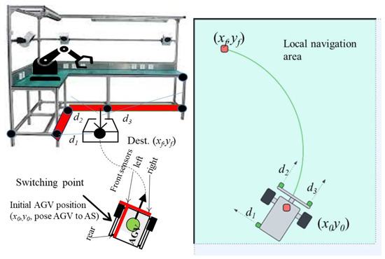
Figure 2.
General concept of local navigation area.
While this research does not delve deeply into the intricacies of the transition between global (dead reckoning, odometry) and local navigation, it is essential to recognize that this switch is an important component in ensuring the AGV’s successful docking.
Given the critical importance of achieving precision in docking, we propose implementation of a fuzzy logic-based system. This approach is suggested to enhance the effectiveness of local navigation (Figure 2) by providing a more adaptive and responsive method for handling the uncertainties and dynamic conditions inherent in the docking process. The following sections will detail how the fuzzy logic controller integrates with the AGV system to improve docking accuracy and operational reliability.
Nevertheless, it must be emphasized that effective switching between global and local modes is essential to ensure the target stopping accuracy of the vehicle at the assembly station.
1.2. Docking Procedure
The docking procedure can be now described in steps:
- Initiation and Mode Switch: The AGV navigates to a predefined switching point (, ) using its global dead reckoning system. Upon reaching this point, the navigation mode seamlessly switches from global to local. This transition is subtle from a operational perspective but fundamental from a control standpoint, as it shifts reliance from odometry to real-time proximity sensor data for final precision maneuvering.
- Relative State Estimation: In the local navigation mode, the AGV continuously acquires distance measurements (), (), and (), from its onboard proximity sensors relative to the L-shaped assembly station. This raw data is processed and fused to estimate the vehicle’s precise relative state. This state is defined by:
- Heading Error: the angular deviation from being parallel to the station.
- Lateral Error: the displacement error perpendicular to the docking direction (e.g., distance to the left wall).
- Longitudinal Error: the remaining distance to travel along the docking axis to reach the final point (, ).
- Fuzzy Logic Control: the estimated state variables (, , ) are fuzzified and fed into the Takagi-Sugeno Fuzzy Logic Controller (FLC). The FLC, operating on its rule base (implemented as a gain-scheduling lookup table), calculates the optimal PWM signals for the left and right wheels. This closed-loop control process continuously adjusts the AGV’s trajectory until the state errors are minimized.
- Docking Completion: The procedure terminates successfully when the AGV’s calculated relative position resides within the acceptable tolerance window of the target destination (xf, yf), defined as . The AGV comes to a full stop, maintaining its position until the next command is received.
2. Fuzzy Logic Controller
Logic controllers based on fuzzy logic [28] are derived from fuzzy sets, a mathematical system that analyzes analog input values in terms of logical variables that take on continuous values between 0 and 1. The fuzzy inference system that controls the AGV is composed of blocks: fuzzification, inference system including rules and defuzzification that can be seen in Figure 3 [29,30].
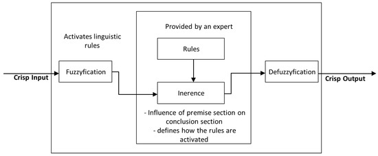
Figure 3.
Structure of fuzzy logic controller (FLC).
The control system utilizes a fuzzy logic architecture. The crisp input values are the distances measured by the onboard proximity sensors. These crisp values are fuzzified using predefined linguistic variables.
The core of the local navigation system is a fuzzy logic controller (FLC) that translates sensor data into motor commands. The FLC was selected for its ability to handle imprecise inputs and nonlinear system dynamics without requiring complex mathematical models or computationally expensive processors, thus aligning with the project’s constraint of using existing hardware [31,32]. The controller’s operation follows a standard architecture:
- Fuzzification: Crisp input values from the distance sensors are mapped into linguistic variables (e.g., “distance” is described by terms such as “very close,” “close,” “optimal,” “far,” and “very far”) using predefined membership functions. This process converts numerical sensor readings into fuzzy sets characterized by degrees of membership between 0 and 1.
- Rule Inference: A set of IF-THEN rules uses these fuzzified inputs to make inferences about the appropriate motor response. The antecedent parts of these rules evaluate the fuzzy inputs, while the consequent parts define the output for each wheel’s PWM value.
- Defuzzification: The aggregated fuzzy output sets from the rule evaluation are converted into a single, crisp value—the precise PWM duty cycle commanded to each wheel’s motor controller in case of Mamdami like system or a function for Takagi-Sugeno system [33,34].
Given the need for computational efficiency and a straightforward implementation in a dynamic industrial environment, the Takagi-Sugeno (Type 1) Fuzzy Inference System was adopted for this project. In the Takagi-Sugeno model, the consequent part of the rules is typically a linear function or a constant, which simplifies the defuzzification process to a weighted average, making it less computationally intensive than the Mamdani model. This efficiency is critical for achieving rapid, real-time control responses on low-cost hardware during the precise docking maneuver.
2.1. Preliminary Assumptions
A predefined accuracy for reaching destination point can be defined as follows:
where xf and yf are coordinates of the docking point, xref and yref are final coordinates of the AGV (after stopping), and are predefined acceptable errors. These values are determined based on the specific requirements of the collaborative task (e.g., the tolerance required for the robotic arm to successfully engage with the load).
The transition from the global navigation system (dead reckoning) to the local fuzzy logic controller (FLC) is triggered at a specific switching point . This point is defined relative to the target assembly station. Upon switching, the coordinate frame of reference for the AGV becomes local, with the origin in its corner (L-shaped). Consequently, the AGV’s position during the entire FLC-controlled docking phase is denoted and tracked relative to this local frame, ensuring the controller’s rules are applied consistently regardless of the AGV’s global position in the facility.
2.2. Fuzzy Input and Output Variables
Fuzzy controller requires linguistic variables at the input and output, so the crisp values are compared to linguistic values that are described by membership functions, e.g., “distance is close” or “distance is OK”, where “distance” is linguistic variable, “close” and “OK” are linguistic values.
The inputs to the fuzzy logic controller (FLC) are the crisp distance measurements acquired from the three proximity sensors, denoted as d1, d2, and d3. Each input variable is defined within its own universe of discourse, a numerical range determined by the operational limits of the corresponding sensor. For example, the variable “distance d1” has a universe of discourse from 2 cm to 2 m, representing its minimum and maximum reliable sensing range. Each linguistic variable (e.g., “distance d1”) is characterized by a set of linguistic values. For this implementation, the set {FAR, CLOSE, OK} was chosen to describe the AGV’s relative position to the assembly station. These values are mathematically represented by trapezoidal membership functions, as illustrated in Figure 4. The trapezoidal membership function is defined by four parameters a, b, c, and d that shapes its profile. The degree of membership for a given crisp input value x is calculated as:
where a, b, c, d are the constants that define the start of the ramp-up, the start of the core, the end of the core, and the end of the ramp-down of the trapezoid, respectively, with . Constants are usually tuned experimentally to optimize the AGV’s docking behavior, balancing responsiveness and stability.
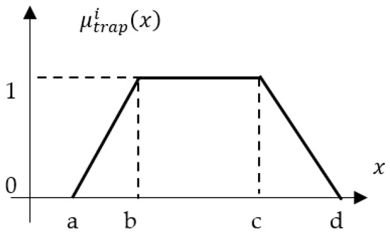
Figure 4.
Trapezoidal membership function.
Given the limited number of physical sensors, two additional linguistic variables were synthesized to provide the fuzzy controller with the necessary state information for precise docking: Alignment (heading error) and Distance Error.
Alignment (Heading Error): This linguistic variable represents the angular deviation () of the AGV with respect to the L-shaped station. It is derived indirectly from the history of readings from the left-side distance sensor d1, under the principle that a changing distance to a parallel surface indicates a rotational drift. To calculate this robustly and reduce noise, a moving average filter with an adjustable window size (e.g., windows size 5) is applied to the d1 sensor readings. The heading error at the time i is then defined:
where is a moving average at the current time step, is a moving average at the previous time step.
This error term is fuzzified into the linguistic variable “Heading Error” with the set of values {NEGATIVE, OK, POSITIVE}. A positive value indicates the AGV is rotating away from the station, while a negative value indicates it is rotating towards it.
The second linguistic variable controls the stopping point and it is labels “distance error”. It is a distance to the front of the L-shaped station. Having two distance sensors on a front bumper, the longitudinal distance error can be formulated:
The third linguistic variable controls the distance between AGV and wall, is called a lateral distance error:
Linguistic variables “distance error” is fuzzified using linguistic values {NEGATIVE, OK, POSITIVE}. All values are defined by trapezoidal membership functions.
The output of the Takagi-Sugeno fuzzy inference system is designed around two conceptual linguistic variables that govern the AGV’s movement in a form of functions. However, to better understand the concept lets introduce linguistic variables:
- “Movement” determines the translational command, with the linguistic values {BACKWARD, STOP, FORWARD}.
- “Rotation” determines the rotational command, with the linguistic values {RIGHT, NO_TURN, LEFT}.
Both variables has impact on coefficients , , , and . The output crisp values are PWML and PWMR for the left and right wheels, respectively. In the Takagi-Sugeno model used in this work, the consequent part of each fuzzy IF-THEN rule is a linear function of the input memberships and a Look Up Table (LUT). The final crisp output for each wheel is calculated as a weighted average of all rule consequents, governed by the following equations (control law):
where , are functions output directly controls left and right motors of AGV, is a constant representing the minimum PWM value required to initiate wheel rotation, overcoming static friction, , are the aggregated membership values (the fuzzy degrees of truth) for the respective input variables, , , , are constant gains tuned experimentally.
The gains determine the influence of each input variable on the motor output and are dependent on factors such as the PWM output range, the AGV’s mass, and motor characteristics. Crucially, the values of these coefficients are dynamically influenced by the current stage of the docking procedure, effectively implementing the conceptual “Movement” and “Rotation” commands.
The inference process for the conceptual output variables “Movement” and “Rotation” is optimized for real-time performance on low-cost hardware. Rather than calculating outputs dynamically, the controller references a pre-defined lookup table (LUT) with predefined coefficients , , , corresponding to every possible combination of the discretized fuzzy input states: heading error, longitudinal error and lateral error.
The design of this LUT embodies the complete set of fuzzy IF-THEN rules.
Each cell in the 3D LUT contains a gain set or parameter set: , , , for that specific operational state. Example: The cell indexed by (HEADING = OK, DX = OK, DY = NEGATIVE) might contain gains (,
,
,
), which would generate a BACKWARD command in the output functions, because the b coefficients are negative and multiply the distance error.
Each entry in the table represents the consequent of a rule, where the indices are the fuzzy values of the inputs (e.g., Heading_Error = NEGATIVE, Distance_Error = OK), and the table cell contains the resulting command pair (Movement, Rotation) (e.g., FORWARD, LEFT) The choice of these linear functions as consequents is a key feature of the Sugeno model, simplifying the defuzzification step to a simple weighted average and reducing computational overhead, which is crucial for real-time performance on low-cost hardware. The procedure can be formulated in three steps:
- State Evaluation: Fuzzify inputs to get indices.
- Gain Scheduling: Use indices to fetch gains (, , , ) from LUT.
- Control Calculation: Compute PWML and PWMR using the control law and the fetched gains.
2.3. LUT as a Gain Scheduler
It retains the speed of a LUT-based approach. The potentially complex calculation of the gains is performed offline; the online controller just performs a fast table lookup and a simple multiply-accumulate operation.
As mentioned earlier the Inputs (LUT Indices):
- Heading Error : {NEGATIVE, OK, POSITIVE}.
- Longitudinal Error : {NEGATIVE, OK, POSITIVE} (Distance to front wall).
- Lateral Error : {NEGATIVE, OK, POSITIVE} (Distance to left wall).
- Outputs (LUT Values): Each cell in the 3D LUT contains a gain set or parameter set: (, , , ) for that specific operational state. To make it readable, the 3D LUT is described in the following 3 tables for NEGATIVE (Table 1), OK (Table 2), and POSITIVE (Table 3).
 Table 1. Too Close to Front Wall (Longitudinal Error NEGATIVE).
 Table 2. At Target Distance (Longitudinal Error OK).
 Table 3. Too Far From Front Wall (Longitudinal Error POSITIVE).
To make it even more understandable, below is the real world interpretation of the rules:
- Too Close and Drifting Left (NEGATIVE, NEGATIVE): (STOP, RIGHT)
- Logic: Emergency stop to avoid collision. Turn right to correct the leftward drift and realign parallel to the left wall.
- Too Close and Parallel (OK, NEGATIVE): (BACKWARD, NO_TURN)
- Logic: Reverse straight back to reach the target distance. Since parallel, no turning is needed.
- Too Close and Drifting Right (POSITIVE, NEGATIVE): (STOP, LEFT)
- Logic: Emergency stop. Turn left to correct the rightward drift and realign.
- Target Distance and Drifting Left (NEGATIVE, OK): (FORWARD, RIGHT)
- Logic: Distance is good but not aligned. Move forward while arcing right to gradually correct heading without losing alignment.
- Target Distance and Parallel (OK, OK): (STOP, NO_TURN)
- Logic: Docking Complete. Perfectly aligned at the correct distance. Stop and hold position.
- Target Distance and Drifting Right (POSITIVE, OK): (FORWARD, LEFT)
- Logic: Mirror of the above. Move forward while arcing left to correct heading.
- Too Far and Drifting Left (NEGATIVE, POSITIVE): (FORWARD, RIGHT)
- Logic: Need to get closer. Move forward while turning right to simultaneously reduce distance and correct heading.
- Too Far and Parallel (OK, POSITIVE): (FORWARD, NO_TURN)
- Logic: Simply move straight forward to reach the target distance.
- Too Far and Drifting Right (POSITIVE, POSITIVE): (FORWARD, LEFT)
- Logic: Need to get closer. Move forward while turning left to correct the drift.
The LUT defines how the AGV should behave in every possible scenario, e.g., tuning according to any high level strategy: “aggressive” for far away, “cautious” when close to the target. The control law executes that strategy smoothly. This separation makes the system easier to design, tune, and debug.
3. Implementation of the Fuzzy Controller
For each input linguistic value, three fuzzy membership functions are defined (Figure 5): positive, ok, negative. The fuzzy controller was implemented using membership coefficients listed in Table 4. These fuzzy sets allow the system to interpret sensor readings and output appropriate motor speeds in a way that accounts for uncertainty and gradations.
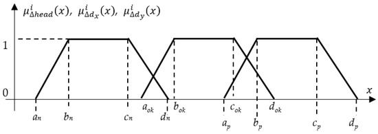
Figure 5.
Distances Membership Functions.

Table 4.
Coefficients for trapezoidal membership functions.
3.1. AGV Platform Overview
The proposed docking system was validated using a custom-built AGV platform. The AGV has a wheelbase (pitch) of 300 mm and a maximum translational velocity of 0.23 m/s. The core of the vehicle is a Raspberry Pi 4 microcontroller, which executes the high-level navigation algorithms, including the global dead reckoning and the proposed fuzzy logic controller. The AGV features a differential drive configuration, powered by two Brushless DC (BLDC) motors with integrated encoders for odometry feedback used in the global navigation phase. Each motor is driven by an H-bridge motor driver circuit, which allows for bi-directional speed control via Pulse Width Modulation (PWM) signals generated by the Raspberry Pi. This setup is illustrated in Figure 6.
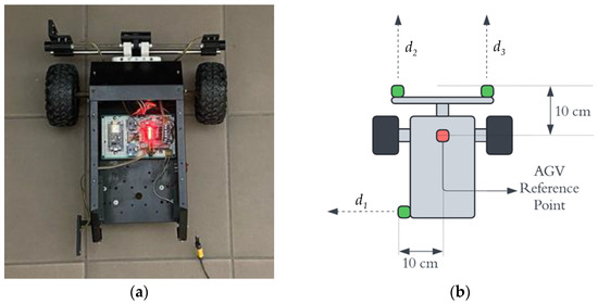
Figure 6.
Top view of the AGV (a); visualization of parameters (b).
For perception in the local navigation phase, the AGV is equipped with a suite of low-cost infrared proximity sensors. These include: a left-facing sensor for measuring lateral distance to the assembly station; two front-facing sensors (, ) for measuring longitudinal distance and calculating lateral offset. The sensors used were VL53L0X Time-of-Flight (ToF) laser ranging modules. Their stated accuracy is ± 3% of the measured distance, with a maximum range of 2 m. This choice was done due to their low cost, small form factor, and digital interface.
3.2. Actuator Characterization and PWM Calibration
A critical prerequisite for precise control was the empirical characterization of the motor response. A series of tests was conducted to determine the operational range of the PWM control signals. Minimum PWM (): The minimum value required to overcome static friction and initiate movement was determined to be (on a 0–255 scale). This ensures reliable motor engagement and was directly applied in the fuzzy control law. Maximum PWM and Velocity Calibration: The maximum PWM value was set to to prevent motor saturation. The AGV’s velocity was calibrated by measuring the time required to traverse a fixed distance of three meters, this yielded a maximum linear velocity of 230 mm/s at .
This calibration defined the effective control range for the fuzzy controller, ensuring its output commands map to predictable and safe vehicle kinematics.
3.3. Reference Points and Performance Metrics
To ensure a reliable assessment of docking performance, reference points were established. The global reference point was defined as the corner (0, 0) of the L-shaped assembly station. The AGV’s performance was measured by calculating the Euclidean error between its final position and this target. A successful docking was defined as a final position within the predefined industrially acceptable tolerances:
Furthermore, the switching point (, ) served as a critical reference for initiating the local navigation procedure. For each experimental trial, the global navigation system was tasked with delivering the AGV to this predefined starting point for the fuzzy controller, ensuring a consistent initial condition for evaluating the local algorithm’s performance across multiple runs.
This framework of reference points provided a consistent basis for comparing experimental results, enabling an accurate statistical assessment of the precision and repeatability of the proposed docking method.
3.4. Testing Setup
The proposed fuzzy logic docking controller was implemented in a Python 3.12 script and evaluated on the AGV platform described in Section 3.1. The primary performance criterion was docking accuracy—specifically, the final positional and angular error from the local navigation phase—rather than travel time or speed. The testing environment and initial conditions for the local navigation phase were defined under the following assumptions:
The target docking station was modeled as an L-shaped corner with dimensions of 350 mm, 350 mm (see Figure 7). The reference point for the final position was defined as the corner (0, 0). The switching points—where global navigation ends and the proposed local fuzzy controller takes over—were defined at four distinct starting positions (SP), given by their coordinates relative to the target corner (0, 0):
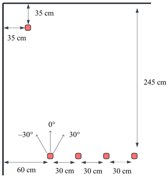
Figure 7.
Visualization of the test procedure.
- SP1 = (600 mm, 2450 mm)
- SP2 = (900 mm, 2450 mm)
- SP3 = (1200 mm, 2450 mm)
- SP4 = (1500 mm, 2450 mm)
At each switching point, the local navigation maneuver began from three initial orientations: −30°, 0°, and + 30°, with the goal of achieving a final heading of 0° (perfect alignment).
3.5. Experimental Procedure
This design of experiment resulted in a total of 12 unique test scenarios (4 switching points × 3 initial angles). Each scenario was executed three times to assess the repeatability and reliability of the fuzzy controller, yielding a total of 36 experimental runs. The AGV’s final docked position and orientation were recorded based on its onboard sensor readings for the closed-loop operation, with validation provided by an external high-accuracy measurement system to ensure ground truth accuracy.
This comprehensive testing matrix was designed to rigorously evaluate the local controller’s performance from various approach vectors, challenging its ability to compensate for both significant positional offsets and angular misalignment after the handover from global navigation.
3.6. Results
Following the experimental procedure outlined in previous section, a full series of tests was conducted. The collected data was systematically analyzed to evaluate the performance of the proposed fuzzy logic controller against the built-in dead reckoning method, which served as the baseline. All tests were executed under controlled conditions to ensure consistency and reproducibility across all trials. The detailed results for each individual test across all starting positions and initial angles are presented in Table 5 (Proposed Fuzzy Logic Controller) and Table 6 (Baseline Dead Reckoning). These tables provide a complete record of the final positional xref, yref and angular aend state for every trial, along with the calculated errors.

Table 5.
Detailed results for Fuzzy Logic Algorithm.

Table 6.
Detailed results for Dead Reckoning Algorithm.
A summary of the experimental results for all test scenarios is provided in Table 7 (Proposed Fuzzy Logic Controller) and Table 8 (Baseline Dead Reckoning). These tables catalog the final docking position , , orientation , and corresponding errors for each individual trial, organized by starting position and initial angle.

Table 7.
Mean Error and Standard Deviation of Error for Fuzzy Logic Algorithm.

Table 8.
Mean Error and Standard Deviation of Error for Dead Reckoning Algorithm.
The aggregate docking performance is visually summarized in Figure 8 (Proposed Fuzzy Logic Controller) and Figure 9 (Baseline Dead Reckoning Algorithm). In both figures, the target destination point is indicated in red, while the final positions of the AGV from all completed trials are plotted in blue. The results demonstrate a significant improvement in both precision and repeatability achieved by the fuzzy logic controller. Figure 8 shows a cluster of blue points around the red target, confirming the system’s accuracy and consistency. Figure 9 reveals a widespread and unpredictable scatter of points for the dead reckoning system, highlighting its fundamental inadequacy for the precision docking task.
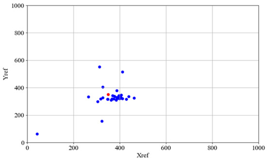
Figure 8.
Docking position for fuzzy controller–coordinates of AGV docking marked by blue dots, the docking point marked by red dot.
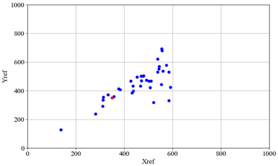
Figure 9.
Docking positions for dead reckoning algorithm–coordinates of AGV docking marked by blue dots, the docking point (, ) marked by red dot.
The overall docking performance for all experimental trials is quantitatively summarized in Table 9, which presents the calculated final positions and orientations for both the proposed fuzzy logic controller and the baseline dead reckoning method. The results demonstrate a definitive and significant general improvement in docking precision achieved by the fuzzy controller. Statistical analysis confirms that only the fuzzy controller consistently achieved performance within the predefined industrially acceptable tolerances. The average final displacement error was reduced to within the required range, and the final angular rotation was maintained at an acceptable level across all starting points and initial conditions. In contrast, the dead reckoning system exhibited substantial and unpredictable errors in both position and angle, failing to meet the required specifications in any of the conducted trials.

Table 9.
Comparison of average error value and standard deviation for all tests (fuzzy controller–bold values).
To elucidate the internal decision-making process of the fuzzy logic controller during a typical docking maneuver, the system’s inputs and outputs for a single exemplary trial are presented. Figure 10 illustrates the real-time distance measurements from the three proximity sensors (d1, d2, d3) as the AGV approaches the station. The corresponding motor control signals (PWM for the left and right wheels), generated by the fuzzy inference system, are shown in Figure 11.
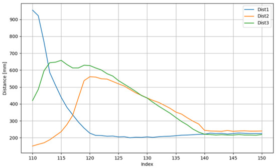
Figure 10.
Exemplary distances to walls from corresponding sensors for a trial.
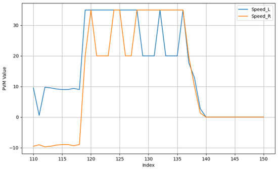
Figure 11.
PWM Output functions for both wheels for a trial.
The sensor data in Figure 10 demonstrates the system’s response to the changing environment, notably the moment the front sensors (d2, d3) detect the approaching station wall. Figure 11 reveals how the controller translates this sensory information into action: the PWM values adjust dynamically, initially to correct the vehicle’s heading and trajectory, and subsequently to reduce speed for a smooth and precise final approach until both motors are commanded to stop (PWM = 0) upon successful docking.
The most precise and repeatable results were obtained with a starting angle of 30° at starting positions SP1 and SP3. As detailed in Table 5 and Table 6, these configurations yielded the lowest absolute error and smallest standard deviation across all trials. For instance at SP1 with a 30° angle, the mean Euclidean error was minimized, with component errors of 17 mm (x-axis, SD = 15 mm) and 36 mm (y-axis, SD = 3 mm). Similarly, at SP3 with a 30° angle, the system demonstrated high repeatability, with standard deviations of 9 mm and 46 mm for the x and y coordinates, respectively. Relatively low errors were also observed with a 0° starting angle at positions SP2 and SP4. For SP2 at 0°, the mean error was 73 mm (x-axis, SD = 29 mm) and 23 mm (y-axis, SD = 6 mm), indicating consistent performance despite the increased distance.
In summary, the proposed fuzzy logic controller consistently achieved lower errors than the dead reckoning baseline. The overall mean positional error for the fuzzy controller was less than 60 mm, while the dead reckoning system exhibited errors frequently exceeding 200 mm. This represents an average improvement in accuracy of over 70%.
The fuzzy logic controller maintained a mean angular deviation below 9 degrees for all scenarios, with most under 5 degrees. Whereas, the dead reckoning system suffered from angular errors, often between 60 and 80 degrees, rendering the AGV completely misaligned at the end of its maneuver.
A practical finding of this research is that the precision of the final docking maneuver is influenced by the conditions at the switching point. The analysis demonstrates that to maximize docking accuracy, the switching point should not be chosen arbitrarily. Based on the experimental results, the following operational guideline should be considered:
The AGV should be oriented with a positive initial heading angle—approximately 30°—relative to the target station when initiating the local navigation phase. This specific approach vector consistently yielded the highest precision and repeatability across multiple starting positions (notably SP1 and SP3), as evidenced by the lowest mean errors and standard deviations reported in Table 6. This finding suggests that the rule base of the developed fuzzy logic controller is particularly effective at compensating for deviations and converging to the target when presented with this specific initial geometric relationship. Therefore, a minor pre-orientation maneuver by the global navigation system to achieve this 30° approach angle at the switching point is recommended to optimize the overall performance and reliability of the docking process.
Our fuzzy rule base and Look-Up Table (LUT) are designed to prioritize lateral alignment first (correcting heading error to become parallel to the station) and longitudinal approach second (closing the distance). A 30° angle presents a structured initial condition that perfectly suits this strategy. The rules for “HEADING = POSITIVE” (e.g., “turn LEFT”) are immediately and strongly activated, efficiently swinging the AGV into alignment.
4. Conclusions
This study addressed the critical challenge of achieving precise AGV docking in industrial environments. Although dead reckoning was a project requirement and can theoretically achieve ± 25 mm accuracy for an unloaded AGV, it proved unreliable in practice.
The proposed solution—a hybrid navigation strategy—was validated by the results. This approach requires an AGV to switch from global navigation (dead reckoning) to a local navigation scheme upon reaching the designated docking area. The local navigation is proposed with the use of a fuzzy logic controller supported by low-cost distance sensors. This architecture combines the broad-range positioning of dead reckoning with precise local correction, overcoming the latter’s fundamental limitations.
The implemented fuzzy logic controller with a gain scheduler demonstrated performance, maintaining angular alignment typically within 10 degrees—a capability good enough for docking: ± 25 mm precision target with a sufficient operational margin. Overall, the fuzzy logic–based method offers a robust, low-cost, and easily implementable software solution for Industry 4.0 environments, ensuring docking accuracy despite uncertainties in, e.g., initial position.
While this study focused on a comparison against the deployed dead reckoning baseline, a valuable direction for future work would be a comprehensive benchmarking study comparing the proposed fuzzy gain-scheduling controller against other advanced methods (e.g., PID, MPC) in a more open experimental setting, independent of specific industrial hardware constraints. Furthermore, the performance of the fuzzy controller could be further refined by employing data-driven optimization techniques, such as clustering or adaptive neuro-fuzzy inference systems (ANFIS), to automatically tune the membership functions and rule base.
Author Contributions
Conceptualization, D.G. and A.Z.; methodology, D.G.; software, Ł.G. and M.G.; validation, D.G., Ł.G. and M.G.; formal analysis, D.G., A.Z., K.P. and L.C.; investigation, Ł.G. and M.G.; resources, A.Z., Ł.G. and M.G.; data curation, Ł.G. and M.G.; writing—original draft preparation, Ł.G., M.G. and D.G.; writing—review and editing, L.C., A.Z., K.P. and D.G.; visualization, Ł.G. and M.G.; supervision, D.G.; project administration, D.G. and A.Z.; funding acquisition, D.G. and A.Z. All authors have read and agreed to the published version of the manuscript.
Funding
This research received no external funding.
Institutional Review Board Statement
Not applicable.
Informed Consent Statement
Not applicable.
Data Availability Statement
The original contributions presented in this study are included in the article material. Further inquiries can be directed to the corresponding author.
Acknowledgments
The research leading to these results received funding from the Norway Grants 2014-2021, which is operated by the National Centre for Research and Development under the project “Automated Guided Vehicles integrated with Collaborative Robots for Smart Industry Perspective” (Project Contract no.: NOR/POLNOR/CoBotAGV/0027/2019-00) and partially by the Polish Ministry of Science and Higher Education Funds for Statutory Research.
Conflicts of Interest
The authors declare no conflicts of interest.
References
- Shi, D.; Mi, H.; Collins, E.G.; Wu, J. An Indoor Low-Cost and High-Accuracy Localization Approach for AGVs. IEEE Access 2020, 8, 50085–50090. [Google Scholar]
- European Commission. Directorate-General for Internal Market, Industry, Entrepreneurship and SMEs. In A Vision for the European Industry Until 2030—Final Report of the Industry 2030 High Level Industrial Roundtable; Publications Office: Luxembourg, 2019. [Google Scholar]
- Wang, S.; Wan, J.; Li, D.; Zhang, C. Implementing Smart Factory of Industrie 4.0: An Outlook. Int. J. Distrib. Sens. Netw. 2016, 12, 3159805. [Google Scholar] [CrossRef]
- Wan, J.; Yi, M.; Li, D.; Zhang, C.; Wang, S.; Zhou, K. Mobile Services for Customization Manufacturing Systems: An Example of Industry 4.0. IEEE Access 2016, 4, 8977–8986. [Google Scholar] [CrossRef]
- Ziebinski, A.; Mrozek, D.; Cupek, R.; Grzechca, D.; Fojcik, M.; Drewniak, M.; Kyrkjebø, E.; Lin, J.C.-W.; Øvsthus, K.; Biernacki, P. Challenges Associated with Sensors and Data Fusion for AGV-Driven Smart Manufacturing. In Proceedings of the Computational Science—ICCS 2021, Cham, Switzerland, 9 June 2021; pp. 595–608. [Google Scholar]
- Maka, A.; Cupek, R.; Wierzchanowski, M. Agent-based Modeling for Warehouse Logistics Systems. In Proceedings of the 2011 UkSim 13th International Conference on Computer Modelling and Simulation, Cambridge, UK, 30 March–1 April 2011; pp. 151–155. [Google Scholar]
- Chang, T.-H.; Hsu, C.-S.; Wang, C.; Yang, L.-K. Onboard Measurement and Warning Module for Irregular Vehicle Behavior. IEEE Trans. Intell. Transp. Syst. 2008, 9, 501–513. [Google Scholar] [CrossRef]
- Roth, H.; Schilling, K. Navigation and docking manoeuvres of mobile robots in industrial environments. In Proceedings of the 24th Annual Conference of the IEEE Industrial Electronics Society, Aachen, Germany, 1 August–4 September 1998; pp. 2458–2462. [Google Scholar]
- Realyvásquez-Vargas, A.; Arredondo-Soto, K.C.; García-Alcaraz, J.L.; Márquez-Lobato, B.Y.; Cruz-García, J. Introduction and configuration of a collaborative robot in an assembly task as a means to decrease occupational risks and increase efficiency in a manufacturing company. Robot. Comput.-Integr. Manuf. 2019, 57, 315–328. [Google Scholar] [CrossRef]
- Kyrkjebø, E. Inertial Human Motion Estimation for Physical Human-Robot Interaction Using an Interaction Velocity Update to Reduce Drift. In Proceedings of the Companion of the 2018 ACM/IEEE International Conference on Human-Robot Interaction, Chicago, IL, USA, 5–8 March 2018; pp. 163–164. [Google Scholar]
- Luo, R.C.; Liao, C.T.; Lin, S.C. Multi-sensor fusion for reduced uncertainty in autonomous mobile robot docking and recharging. In Proceedings of the 2009 IEEE/RSJ International Conference on Intelligent Robots and Systems, St. Louis, MO, USA, 10–15 October 2009; pp. 2203–2208. [Google Scholar]
- Deilamsalehy, H.; Havens, T.C. Sensor fused three-dimensional localization using IMU, camera and LiDAR. In Proceedings of the 2016 IEEE SENSORS, Orlando, FL, USA, 30 October–3 November 2016; pp. 1–3. [Google Scholar]
- Ziebinski, A.; Cupek, R.; Nalepa, M. Obstacle Avoidance by a Mobile Platform Using an Ultrasound Sensor. In Proceedings of the Computational Collective Intelligence (ICCCI 2017), Nicosia, Cyprus, 27–29 September 2017; pp. 238–248. [Google Scholar]
- Kim, K.-E.; Lee, C.-J.; Pae, D.-S.; Lim, M.-T. Sensor fusion for vehicle tracking with camera and radar sensor. In Proceedings of the 2017 17th International Conference on Control, Automation and Systems (ICCAS), Jeju, Republic of Korea, 18–21 October 2017. [Google Scholar]
- Hellmers, H.; Eichhorn, A.; Norrdine, A.; Blankenbach, J. Indoor localisation for wheeled platforms based on IMU and artificially generated magnetic field. In Proceedings of the 2014 Ubiquitous Positioning Indoor Navigation and Location Based Service (UPINLBS), Corpus Christ, TX, USA, 20–21 November 2014; pp. 255–264. [Google Scholar]
- Ziebinski, A.; Bregulla, M.; Fojcik, M.; Klak, S. Monitoring and Controlling Speed for an Autonomous Mobile Platform Based on the Hall Sensor. In Proceedings of the Computational Collective Intelligence (ICCCI 2017), Nicosia, Cyprus, 27–29 September 2017; pp. 249–259. [Google Scholar]
- Liggins II, M.; Hall, D.; Llinas, J. Handbook of Multisensor Data Fusion: Theory and Practice, 2nd ed.; CRC Press: Boca Raton, FL, USA, 2017. [Google Scholar]
- Błachuta, M.; Czyba, R.; Janusz, W.; Szafrański, G. Data Fusion Algorithm for the Altitude and Vertical Speed Estimation of the VTOL Platform. J. Intell. Robot. Syst. 2014, 74, 413–420. [Google Scholar] [CrossRef]
- Wang, W.; Bao, Z.; Zheng, J.; Wang, T. Research on automated guided vehicle (AGV) path tracking control based on laser simultaneous localization and mapping (SLAM). Mech. Sci. 2025, 16, 1–24. [Google Scholar] [CrossRef]
- Biernacki, P.; Ziębiński, A.; Grzechca, D. The Adaptive Calibration Method for Single-Beam Distance Sensors. In Proceedings of the Computational Collective Intelligence (ICCCI 2021), Rhodes, Greece, 29 September–1 October 2021; pp. 721–732. [Google Scholar]
- Tokarz, K.; Czekalski, P.; Sieczkowski, W. Integration of ultrasonic and inertial methods in indoor navigation system. Theor. Appl. Inform. 2014, 26, 107–117. [Google Scholar]
- Grzechca, D.; Ziębiński, A.; Paszek, K.; Hanzel, K.; Giel, A.; Czerny, M.; Becker, A. How Accurate Can UWB and Dead Reckoning Positioning Systems Be? Comparison to SLAM Using the RPLidar System. Sensors 2020, 20, 3761. [Google Scholar] [CrossRef] [PubMed]
- Lau, H.C.W.; Cheng, E.N.M.; Lee, C.K.M.; Ho, G.T.S. A fuzzy logic approach to forecast energy consumption change in a manufacturing system. Expert Syst. Appl. 2008, 34, 1813–1824. [Google Scholar] [CrossRef]
- Lee, M.C.; Park, M.G. Artificial potential field based path planning for mobile robots using a virtual obstacle concept. In Proceedings of the 2003 IEEE/ASME International Conference on Advanced Intelligent Mechatronics (AIM 2003), Kobe, Japan, 20–24 July 2003; pp. 735–740. [Google Scholar]
- Nwoba, E.G.; Chuka-Ogwude, D.; Vadiveloo, A.; Ogbonna, J.C. 6-Process Control Strategies Applied to Microalgae-Based Biofuel Production; Woodhead Publishing: Cambridge, UK, 2022. [Google Scholar]
- Fang, B.T. Trilateration and extension to Global Positioning System navigation. J. Guid. Control Dyn. 1986, 9, 715–717. [Google Scholar] [CrossRef]
- Ziebinski, A.; Cupek, R.; Piech, A. Distributed control architecture for the autonomous mobile platform. In Proceedings of the International Conference of Computational Methods in Sciences and Engineering 2018 (ICCMSE 2018), Thessaloniki, Greece, 14–18 March 2018. [Google Scholar]
- Zadeh, L.A. Fuzzy Sets. Inf. Control 1965, 8, 338–353. [Google Scholar] [CrossRef]
- Zadeh, L.A. Outline of a New Approach to the Analysis of Complex Systems and Decision Processes. IEEE Trans. Syst. Man Cybern. 1973, SMC-3, 28–44. [Google Scholar] [CrossRef]
- Mendel, J.M. Fuzzy Logic Systems for Engineering: A Tutorial. Proc. IEEE 1995, 83, 345–377. [Google Scholar] [CrossRef]
- Villagra, J.; Herrero-Perez, D. A Comparison of Control Techniques for Robust Docking Maneuvers of an AGV. IEEE Trans. Control. Syst. Technol. 2012, 20, 1116–1123. [Google Scholar] [CrossRef]
- Kodagoda, K.R.S.; Wijesoma, W.S.; Teoh, E.K. Fuzzy speed and steering control of an AGV. IEEE Trans. Control Syst. Technol. 2002, 10, 112–120. [Google Scholar] [CrossRef]
- Mamdani, E.H. Application of Fuzzy Algorithms for Control of Simple Dynamic Plant. Proc. Inst. Electr. Eng. 1974, 121, 1585–1588. [Google Scholar] [CrossRef]
- Takagi, T.; Sugeno, M. Fuzzy Identification of Systems and Its Applications to Modeling and Control. IEEE Trans. Syst. Man Cybern. 1985, SMC-15, 116–132. [Google Scholar] [CrossRef]
Disclaimer/Publisher’s Note: The statements, opinions and data contained in all publications are solely those of the individual author(s) and contributor(s) and not of MDPI and/or the editor(s). MDPI and/or the editor(s) disclaim responsibility for any injury to people or property resulting from any ideas, methods, instructions or products referred to in the content. |
© 2025 by the authors. Licensee MDPI, Basel, Switzerland. This article is an open access article distributed under the terms and conditions of the Creative Commons Attribution (CC BY) license (https://creativecommons.org/licenses/by/4.0/).