Figure 1.
Dimensional sketch of the electromagnet, a/b [m]—length/width of the electromagnet core, δ [m]—armature clearance (air gap).
Figure 1.
Dimensional sketch of the electromagnet, a/b [m]—length/width of the electromagnet core, δ [m]—armature clearance (air gap).
Figure 2.
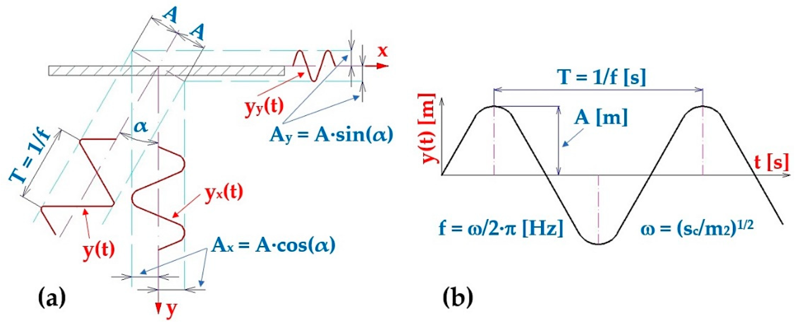
Harmonic oscillation of the vibrating conveyor trough, (a) components yx(t) [m] a yy(t) [m] of the trough deflection, (b) harmonic oscillation parameters.
Figure 2.
Harmonic oscillation of the vibrating conveyor trough, (a) components yx(t) [m] a yy(t) [m] of the trough deflection, (b) harmonic oscillation parameters.
Figure 3.
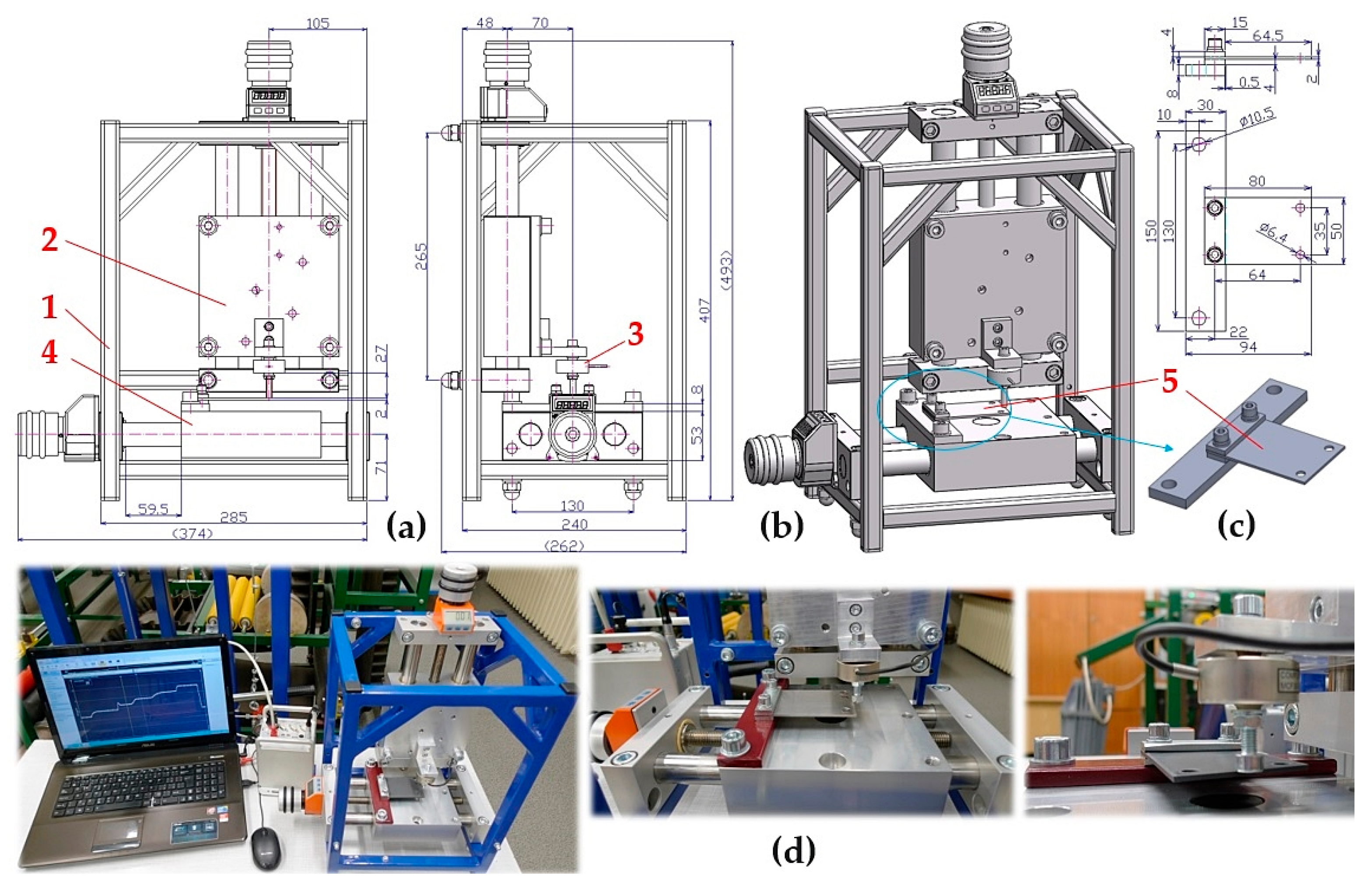
Laboratory device for detecting the magnitude of the electromagnet’s holding force: (a) 2D dimensional sketch, (b) 3D model, (c) implementation. 1—electromagnet, 2—electromagnet armature, 3—force sensor, 4—support frame.
Figure 3.
Laboratory device for detecting the magnitude of the electromagnet’s holding force: (a) 2D dimensional sketch, (b) 3D model, (c) implementation. 1—electromagnet, 2—electromagnet armature, 3—force sensor, 4—support frame.
Figure 4.
Measuring chain—a sequence of interconnected instruments and devices that enable the detection and processing of measured signals.
Figure 4.
Measuring chain—a sequence of interconnected instruments and devices that enable the detection and processing of measured signals.
Figure 5.
(a) leaf springs made of FR4 Epoxy, (b) deflection yMijk [m] of a leaf spring of length Ls [m] loaded with force FMijk [N], (c) measuring the deflection of the leaf spring on laboratory device.
Figure 5.
(a) leaf springs made of FR4 Epoxy, (b) deflection yMijk [m] of a leaf spring of length Ls [m] loaded with force FMijk [N], (c) measuring the deflection of the leaf spring on laboratory device.
Figure 6.
Laboratory device for measuring the stiffness of leaf springs, (a) dimensional sketch, (b) 3D model, (c) attachment of the leaf spring to the flat bar by a bolted connection, (d) implemented device. 1—steel frame, 2, 4—positioning table PT7312-PA, 3—MCF30-500 force transducer, 5—leaf spring.
Figure 7.
The vibrating feeder with electromagnetic vibration exciter (a) dimensional sketch and 3D model, (b) implemented measuring device. 1—steel trough, 2—steel frame, 3—leaf spring, 4—electromagnet, 5—armature of the electromagnet, 6—amplitude/frequency regulator—FQ1 DIG.
Figure 7.
The vibrating feeder with electromagnetic vibration exciter (a) dimensional sketch and 3D model, (b) implemented measuring device. 1—steel trough, 2—steel frame, 3—leaf spring, 4—electromagnet, 5—armature of the electromagnet, 6—amplitude/frequency regulator—FQ1 DIG.
Figure 8.
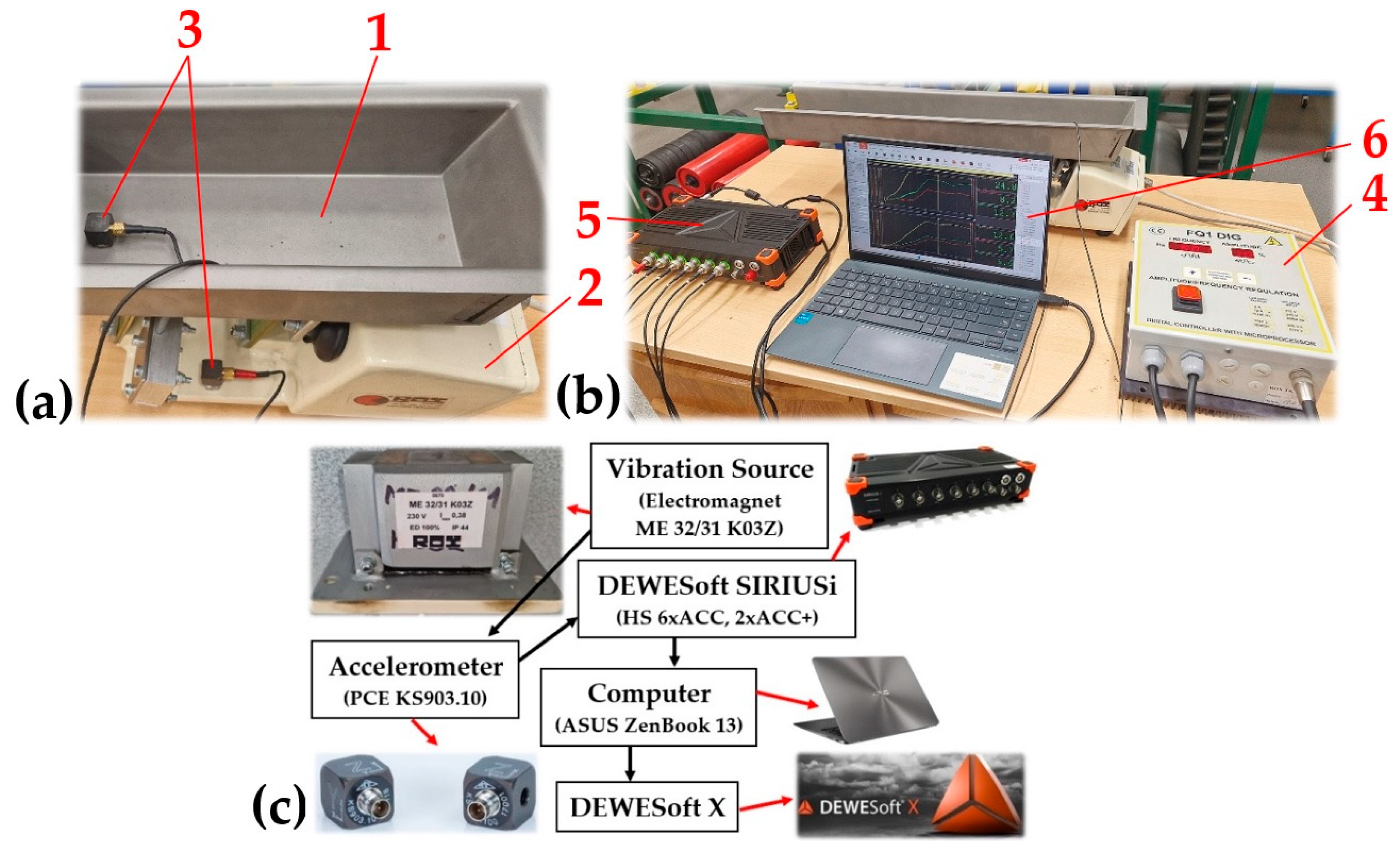
The vibrating feeder with electromagnetic vibration exciter. (a) placement of sensors on the trough and the feeder frame, (b) control unit and display computer, (c) measuring chain. 1—steel trough, 2—steel frame, 3—acceleration sensors, 4—amplitude/frequency controller, 5—measuring apparatus, 6—PC with DEWESoft X software.
Figure 11.
Measured values of the compressive force (a) FM11k [N], (b) FM21k [N], which produces the deflection yMK [mm] of the end part of the leaf spring No. 1, made of FR4 Epoxy.
Figure 11.
Measured values of the compressive force (a) FM11k [N], (b) FM21k [N], which produces the deflection yMK [mm] of the end part of the leaf spring No. 1, made of FR4 Epoxy.
Figure 12.
Measured values of the compressive force (a) FM22k [N] and (b) FM32k [N], which produces the deflection yMK [mm] of the end part of the leaf spring No. 2, made of FR4 Epoxy.
Figure 12.
Measured values of the compressive force (a) FM22k [N] and (b) FM32k [N], which produces the deflection yMK [mm] of the end part of the leaf spring No. 2, made of FR4 Epoxy.
Figure 13.
Measured values of the compressive force (a) FM35k [N] and (b) FM16k [N], which produces the deflection yMK [mm] of the end part of the leaf spring No. 5 and No. 6, made of Steel.
Figure 13.
Measured values of the compressive force (a) FM35k [N] and (b) FM16k [N], which produces the deflection yMK [mm] of the end part of the leaf spring No. 5 and No. 6, made of Steel.
Figure 15.
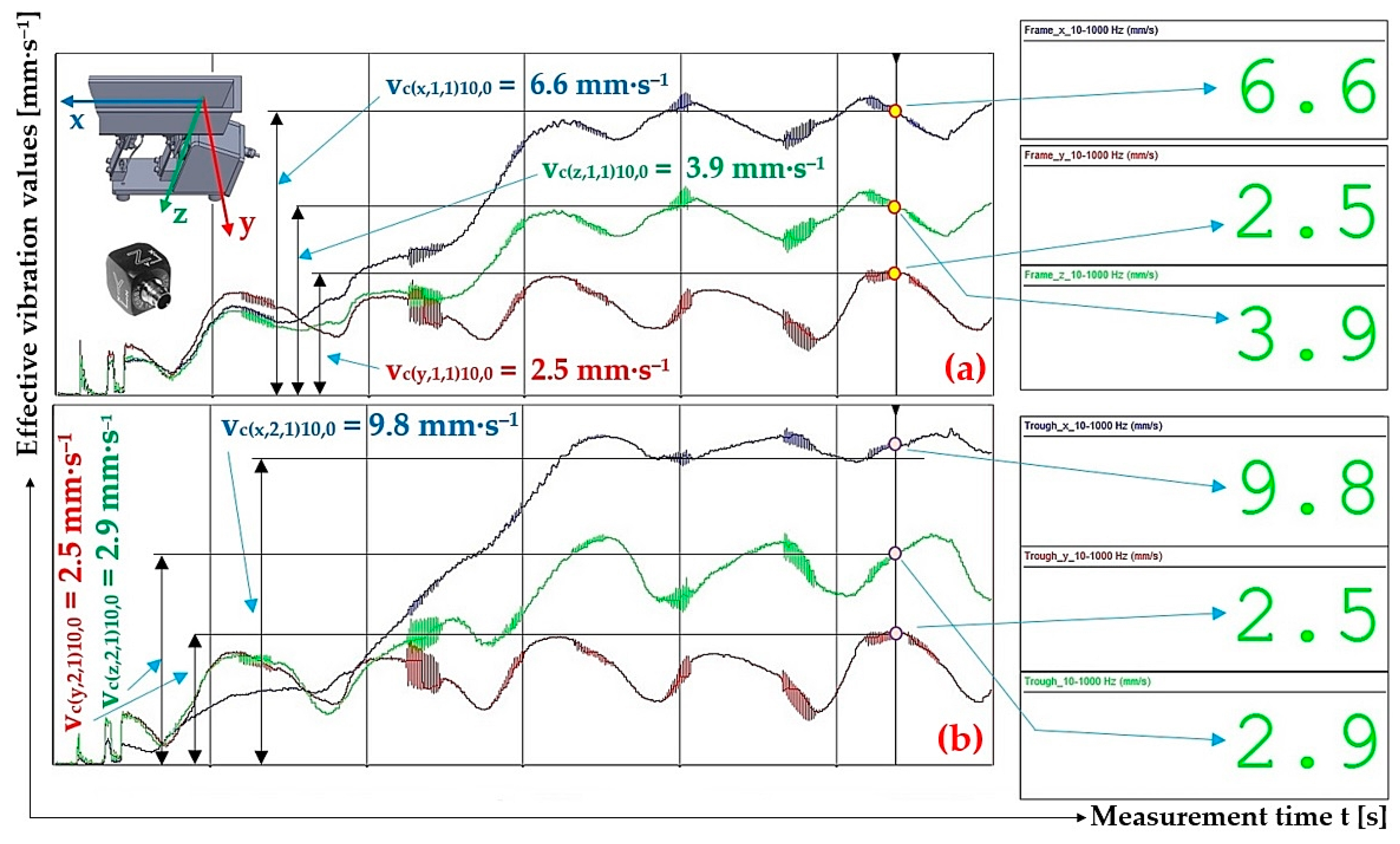
Measured values of effective vibration velocities vc(l,i,1)10,0 [mm·s−1] in three mutually perpendicular planes of (a) trough supported by 4 FR4 Epoxy leaf springs, (b) steel frame of vibrating feeder.
Figure 15.
Measured values of effective vibration velocities vc(l,i,1)10,0 [mm·s−1] in three mutually perpendicular planes of (a) trough supported by 4 FR4 Epoxy leaf springs, (b) steel frame of vibrating feeder.
Figure 16.
Measured values of the effective vibration velocity vc(x,i,1)20,2.57 [mm·s−1] in the direction of the x-axis of the trough (supported by 4 FR4 Epoxy leaf springs) and the steel frame of the vibrating feeder.
Figure 16.
Measured values of the effective vibration velocity vc(x,i,1)20,2.57 [mm·s−1] in the direction of the x-axis of the trough (supported by 4 FR4 Epoxy leaf springs) and the steel frame of the vibrating feeder.
Figure 17.
Measured values of the effective vibration velocity vc(x,i,1)30,5.099 [mm·s−1] in the direction of the x-axis of the trough (supported by 4 FR4 Epoxy leaf springs) and the steel frame of the vibrating feeder.
Figure 17.
Measured values of the effective vibration velocity vc(x,i,1)30,5.099 [mm·s−1] in the direction of the x-axis of the trough (supported by 4 FR4 Epoxy leaf springs) and the steel frame of the vibrating feeder.
Figure 18.
Measured values of the effective vibration velocity vs(x,i,2)10,0 [mm·s−1] in the direction of the x-axis of the trough (supported by 2 steel leaf springs) and the steel frame of the vibrating feeder.
Figure 18.
Measured values of the effective vibration velocity vs(x,i,2)10,0 [mm·s−1] in the direction of the x-axis of the trough (supported by 2 steel leaf springs) and the steel frame of the vibrating feeder.
Figure 19.
Measured values of the effective vibration velocity vs(x,i,2)20,2.57 [mm·s−1] in the direction of the x-axis of the trough (supported by 2 steel leaf springs) and the steel frame of the vibrating feeder.
Figure 19.
Measured values of the effective vibration velocity vs(x,i,2)20,2.57 [mm·s−1] in the direction of the x-axis of the trough (supported by 2 steel leaf springs) and the steel frame of the vibrating feeder.
Figure 20.
Measured values of the effective vibration velocity vs(x,i,2)30,5.099 [mm·s−1] in the direction of the x-axis of the trough (supported by 2 steel leaf springs) and the steel frame of the vibrating feeder.
Figure 20.
Measured values of the effective vibration velocity vs(x,i,2)30,5.099 [mm·s−1] in the direction of the x-axis of the trough (supported by 2 steel leaf springs) and the steel frame of the vibrating feeder.
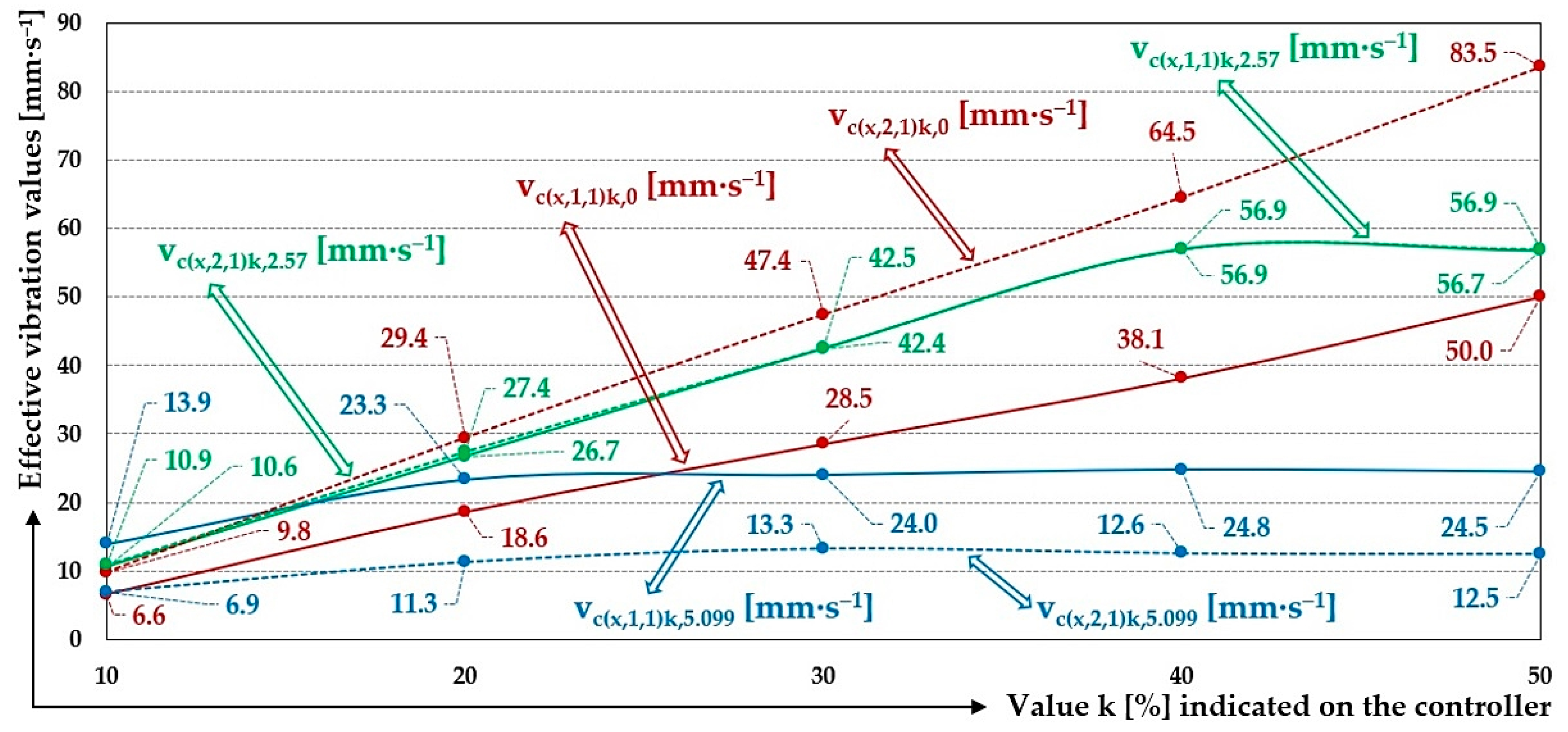
Figure 21.
Measured values of the effective vibration velocities vc(x,i,j)k,m [mm·s−1] of the oscillation of the steel frame (continuous curve) and trough (dashed curve) of the vibrating feeder with various values of k [%] and the selected material of the leaf springs FR4 Epoxy.
Figure 21.
Measured values of the effective vibration velocities vc(x,i,j)k,m [mm·s−1] of the oscillation of the steel frame (continuous curve) and trough (dashed curve) of the vibrating feeder with various values of k [%] and the selected material of the leaf springs FR4 Epoxy.
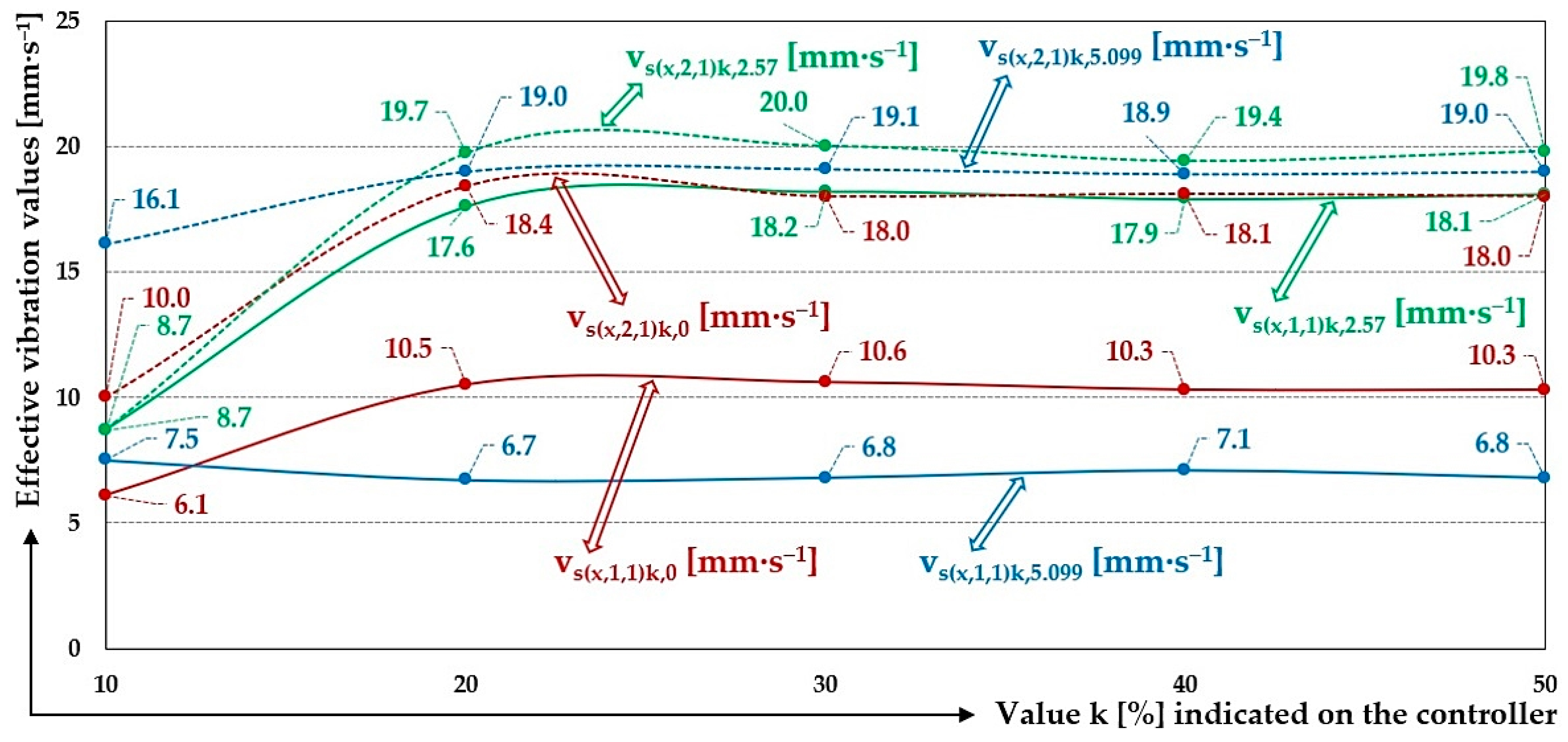
Figure 22.
Measured values of the effective vibration velocities vs(x,i,j)k,m [mm·s−1] of the oscillation of the steel frame (continuous curve) and trough (dashed curve) of the vibrating feeder with various values of k [%] and the selected material of the leaf springs steel.
Figure 22.
Measured values of the effective vibration velocities vs(x,i,j)k,m [mm·s−1] of the oscillation of the steel frame (continuous curve) and trough (dashed curve) of the vibrating feeder with various values of k [%] and the selected material of the leaf springs steel.
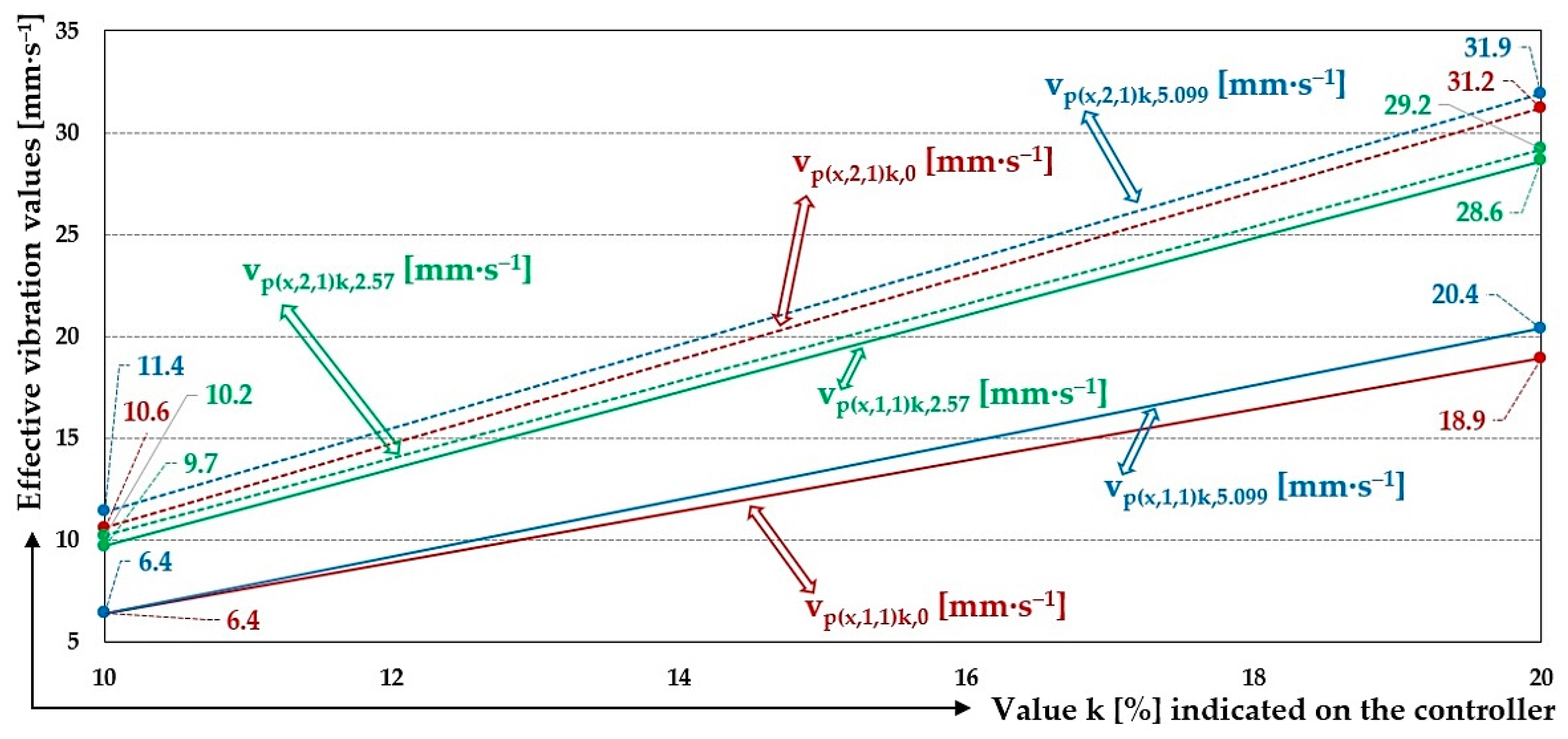
Figure 23.
Measured values of the effective vibration velocities vp(x,i,j)k,m [mm·s−1] of the oscillation of the steel frame (continuous curve) and trough (dashed curve) of the vibrating feeder with various values of k [%] and the selected material of the leaf springs Plastic PCCF.
Figure 23.
Measured values of the effective vibration velocities vp(x,i,j)k,m [mm·s−1] of the oscillation of the steel frame (continuous curve) and trough (dashed curve) of the vibrating feeder with various values of k [%] and the selected material of the leaf springs Plastic PCCF.
Table 2.
Stiffness of leaf spring No. 1 (j = 1). Thickness ts = 1.9 mm, material—FR4 Epoxy.
Table 2.
Stiffness of leaf spring No. 1 (j = 1). Thickness ts = 1.9 mm, material—FR4 Epoxy.
| k | j = 1 |
|---|
| i | 1 | 2 | 3 |
|---|
| yMk [mm] | FMijk [N] 1 | scijk [N·mm−1] | FMijk [N] 2 | scijk [N·mm−1] | FMijk [N] | scijk [N·mm−1] |
|---|
| 0 | 0 | 0 | 0 | 0 | 0 | 0 | 0 |
| 1 | 0.5 | 4.3 | 8.6 | 4.2 | 8.4 | 4.2 | 8.4 |
| 2 | 1 | 8.6 | 8.6 | 8.5 | 8.5 | 8.4 | 8.4 |
| 3 | 1.5 | 13.0 | 8.7 | 12.8 | 8.5 | 12.8 | 8.5 |
| 4 | 2 | 17.4 | 8.7 | 17.4 | 8.7 | 17.3 | 8.7 |
| 5 | 2.5 | 21.9 | 8.8 | 21.9 | 8.8 | 21.9 | 8.8 |
| 8.7 | 8.6 | 8.5 |
| 8.6 |
| 0.2 |
| 8.6 ± 0.2 |
Table 3.
Stiffness of leaf spring No. 2 (j = 2). Thickness ts = 2.3 mm, material—FR4 Epoxy.
Table 3.
Stiffness of leaf spring No. 2 (j = 2). Thickness ts = 2.3 mm, material—FR4 Epoxy.
| k | j = 2 |
|---|
| i | 1 | 2 | 3 |
|---|
| yMk [mm] | FMijk [N] | scijk [N·mm−1] | FMijk [N] 1 | scijk [N·mm−1] | FMijk [N] 2 | scijk [N·mm−1] |
|---|
| 0 | 0 | 0 | 0 | 0 | 0 | 0 | 0 |
| 1 | 0.5 | 9.5 | 19.0 | 9.1 | 18.2 | 9.2 | 18.4 |
| 2 | 1 | 19.5 | 19.5 | 19.0 | 19.0 | 18.8 | 18.8 |
| 3 | 1.5 | 29.1 | 19.4 | 28.9 | 19.3 | 28.8 | 19.2 |
| 4 | 2 | 38.7 | 19.4 | 38.5 | 19.3 | 38.4 | 19.2 |
| 5 | 2.5 | 48.5 | 19.4 | 48.6 | 19.4 | 48.4 | 19.4 |
| 19.3 | 19.0 | 19.0 |
| 19.1 |
| 0.3 |
| 19.1 ± 0.3 |
Table 4.
Stiffness of leaf spring No. 3 (j = 3). Thickness ts = 1.9 mm, material—FR4 Epoxy.
Table 4.
Stiffness of leaf spring No. 3 (j = 3). Thickness ts = 1.9 mm, material—FR4 Epoxy.
| k | j = 3 |
|---|
| i | 1 | 2 | 3 |
|---|
| yMk [mm] | FMijk [N] | scijk [N·mm−1] | FMijk [N] | scijk [N·mm−1] | FMijk [N] | scijk [N·mm−1] |
|---|
| 0 | 0 | 0 | 0 | 0 | 0 | 0 | 0 |
| 1 | 0.5 | 3.2 | 6.4 | 3.1 | 6.2 | 3.1 | 6.2 |
| 2 | 1 | 6.5 | 6.5 | 6.4 | 6.4 | 6.4 | 6.4 |
| 3 | 1.5 | 9.7 | 6.5 | 9.7 | 6.5 | 9.7 | 6.5 |
| 4 | 2 | 13.0 | 6.5 | 13.0 | 6.5 | 13.1 | 6.6 |
| 5 | 2.5 | 16.4 | 6.6 | 16.5 | 6.6 | 16.5 | 6.6 |
| 6.5 | 6.4 | 6.4 |
| 6.4 |
| 0.1.3 |
| 6.4 ± 0.1 |
Table 5.
Stiffness of leaf spring No. 4 (j = 4). Thickness ts = 2.3 mm, material—FR4 Epoxy.
Table 5.
Stiffness of leaf spring No. 4 (j = 4). Thickness ts = 2.3 mm, material—FR4 Epoxy.
| k | j = 4 |
|---|
| i | 1 | 2 | 3 |
|---|
| yMk [mm] | FMijk [N] | scijk [N·mm−1] | FMijk [N] | scijk [N·mm−1] | FMijk [N] | scijk [N·mm−1] |
|---|
| 0 | 0 | 0 | 0 | 0 | 0 | 0 | 0 |
| 1 | 0.5 | 6.8 | 13.6 | 6.5 | 13.0 | 6.5 | 13.0 |
| 2 | 1 | 13.9 | 13.9 | 13.6 | 13.6 | 13.6 | 13.6 |
| 3 | 1.5 | 20.8 | 13.9 | 20.7 | 13.8 | 20.7 | 13.8 |
| 4 | 2 | 27.9 | 14.0 | 27.7 | 13.9 | 27.7 | 13.9 |
| 5 | 2.5 | 34.9 | 14.0 | 34.8 | 13.9 | 35.0 | 14.0 |
| 13.9 | 13.6 | 13.7 |
| 13.7 |
| 0.3 |
| 13.7 ± 0.3 |
Table 6.
Stiffness of leaf spring No. 5 (j = 5). Thickness ts = 2.0 mm, material—Steel.
Table 6.
Stiffness of leaf spring No. 5 (j = 5). Thickness ts = 2.0 mm, material—Steel.
| k | j = 5 |
|---|
| i | 1 | 2 | 3 |
|---|
| yMk [mm] | FMijk [N] | scijk [N·mm−1] | FMijk [N] | scijk [N·mm−1] | FMijk [N] 1 | scijk [N·mm−1] |
|---|
| 0 | 0 | 0 | 0 | 0 | 0 | 0 | 0 |
| 1 | 0.5 | 29.9 | 59.8 | 29 | 58.0 | 29.3 | 58.6 |
| 2 | 1 | 57.4 | 57.4 | 57.6 | 57.6 | 58.6 | 58.6 |
| 3 | 1.5 | 76.7 | 51.1 | 77.5 | 51.7 | 77.6 | 51.7 |
| 4 | 2 | 98.1 | 49.1 | 97.4 | 48.7 | 95.3 | 47.7 |
| 54.3 | 54.0 | 54.1 |
| 54.1 |
| 0.3 |
| 54.1 ± 0.3 |
Table 7.
Stiffness of leaf spring No. 6 (j = 6). Thickness ts = 2.0 mm, material—Steel.
Table 7.
Stiffness of leaf spring No. 6 (j = 6). Thickness ts = 2.0 mm, material—Steel.
| k | j = 6 |
|---|
| i | 1 | 2 | 3 |
|---|
| yMk [mm] | FMijk [N] 1 | scijk [N·mm−1] | FMijk [N] | scijk [N·mm−1] | FMijk [N] | scijk [N·mm−1] |
|---|
| 0 | 0 | 0 | 0 | 0 | 0 | 0 | 0 |
| 1 | 0.5 | 28.1 | 56.9 | 28.0 | 56.0 | 28.5 | 57.0 |
| 2 | 1 | 56.9 | 51.6 | 57.1 | 57.1 | 57.0 | 57.0 |
| 3 | 1.5 | 77.4 | 46.9 | 76.5 | 51.0 | 77.2 | 51.5 |
| 4 | 2 | 93.7 | 56.2 | 92.9 | 46.5 | 96.1 | 48.1 |
| 52.9 | 52.6 | 53.4 |
| 53.0 |
| 0.7 |
| 53.0 ± 0.7 |
Table 9.
Effective vibration velocities vc(x,i,j)k,0 [mm·s−1] of the steel frame (i = 1) and trough (i = 2) measured in the “x” axis (l = x) of the coordinate system. Load weight m = 0 kg, leaf spring material FR4 Epoxy (* = c).
Table 9.
Effective vibration velocities vc(x,i,j)k,0 [mm·s−1] of the steel frame (i = 1) and trough (i = 2) measured in the “x” axis (l = x) of the coordinate system. Load weight m = 0 kg, leaf spring material FR4 Epoxy (* = c).
| * | c (FR4 Epoxy) |
|---|
| mq | 0 kg |
|---|
| i | 1—Frame | | | |
| j | 1 | 2 | 3 |
| k [%] | |
| 10 | 6.6 1 | 6.4 | 6.5 | 6.5 | 0.2 | 6.5 ± 0.2 |
| 20 | 18.6 | 18.5 | 18.6 | 18.6 | 0.1 | 18.6 ± 0.1 |
| 30 | 28.5 | 28.8 | 28.7 | 28.7 | 0.3 | 28.7 ± 0.3 |
| 40 | 38.1 | 38.8 | 38.6 | 38.5 | 0.6 | 38.5 ± 0.6 |
| 50 | 50.0 | 49.7 | 49.9 | 49.9 | 0.3 | 49.9 ± 0.3 |
| i | 2—Trough | | | |
| j | 1 | 2 | 3 |
| k [%] | |
| 10 | 9.8 2 | 10.2 | 10.1 | 10.0 | 0.4 | 10.0 ± 0.4 |
| 20 | 28.6 | 29.4 | 28.8 | 28.9 | 0.7 | 28.9 ± 0.7 |
| 30 | 47.4 | 47.8 | 47.7 | 47.6 | 0.4 | 47.6 ± 0.4 |
| 40 | 64.5 | 65.7 | 65.2 | 65.1 | 1.0 | 65.1 ± 1.0 |
| 50 | 83.5 | 83.1 | 83.4 | 83.3 | 0.4 | 83.3 ± 0.4 |
Table 10.
Effective vibration velocities vc(x,i,j)k,2.57 [mm·s−1] of the steel frame (i = 1) and trough (i = 2) measured in the “x” axis of the coordinate system. Load weight m = 2.57 kg, leaf spring material FR4 Epoxy (* = c).
Table 10.
Effective vibration velocities vc(x,i,j)k,2.57 [mm·s−1] of the steel frame (i = 1) and trough (i = 2) measured in the “x” axis of the coordinate system. Load weight m = 2.57 kg, leaf spring material FR4 Epoxy (* = c).
| * | c (FR4 Epoxy) |
|---|
| mq | 2.57 kg |
|---|
| i | 1—Frame | | | |
| j | 1 | 2 | 3 |
| k | |
| [%] | [mm·s−1] |
| 10 | 10.6 | 10.1 | 10.5 | 10.4 | 0.5 | 10.4 ± 0.5 |
| 20 | 26.7 1 | 25.9 | 26.5 | 26.4 | 0.7 | 26.4 ± 0.7 |
| 30 | 42.4 | 42.7 | 42.6 | 42.6 | 0.3 | 42.6 ± 0.3 |
| 40 | 56.9 | 56.6 | 56.8 | 56.8 | 0.3 | 56.8 ± 0.3 |
| 50 | 56.7 | 56.6 | 56.7 | 56.7 | 0.1 | 56.7 ± 0.1 |
| i | 2—Trough | | | |
| j | 1 | 2 | 3 |
| k | |
| [%] | [mm·s−1] |
| 10 | 10.9 | 10.6 | 10.5 | 10.7 | 0.4 | 10.7 ± 0.4 |
| 20 | 27.4 1 | 26.6 | 27.0 | 27.0 | 0.6 | 27.0 ± 0.6 |
| 30 | 42.5 | 43.0 | 43.1 | 42.9 | 0.6 | 42.9 ± 0.6 |
| 40 | 56.9 | 56.6 | 56.9 | 56.8 | 0.3 | 56.8 ± 0.3 |
| 50 | 56.9 | 56.6 | 56.8 | 56.8 | 0.3 | 56.8 ± 0.3 |
Table 11.
Effective vibration velocities vc(x,i,j)k,5.099 [mm·s−1] of the steel frame (i = 1) and trough (i = 2) measured in the “x” axis of the coordinate system. Load weight m = 5.099 kg, leaf spring material FR4 Epoxy (* = c).
Table 11.
Effective vibration velocities vc(x,i,j)k,5.099 [mm·s−1] of the steel frame (i = 1) and trough (i = 2) measured in the “x” axis of the coordinate system. Load weight m = 5.099 kg, leaf spring material FR4 Epoxy (* = c).
| * | c (FR4 Epoxy) |
|---|
| mq | 5.099 kg |
|---|
| i | 1—Frame | | | |
| j | 1 | 2 | 3 |
| k | |
| [%] | [mm·s−1] |
| 10 | 13.9 | 13.8 | 13.8 | 13.8 | 0.1 | 13.8 ± 0.1 |
| 20 | 23.3 | 22.8 | 23.2 | 23.1 | 0.5 | 23.1 ± 0.5 |
| 30 | 24.0 1 | 24.3 | 24.2 | 24.2 | 0.3 | 24.2 ± 0.3 |
| 40 | 24.8 | 24.6 | 24.5 | 24.6 | 0.3 | 24.6 ± 0.3 |
| 50 | 24.5 | 24.6 | 24.7 | 24.6 | 0.2 | 24.6 ± 0.2 |
| i | 2—Trough | | | |
| j | 1 | 2 | 3 |
| k | |
| [%] | [mm·s−1] |
| 10 | 6.9 | 7.2 | 7.2 | 7.1 | 0.3 | 7.1 ± 0.3 |
| 20 | 11.3 | 11.8 | 11.6 | 11.6 | 0.4 | 11.6 ± 0.4 |
| 30 | 13.3 1 | 12.9 | 13.1 | 13.1 | 0.3 | 13.1 ± 0.3 |
| 40 | 12.6 | 12.5 | 12.5 | 12.5 | 0.1 | 12.5 ± 0.1 |
| 50 | 12.5 | 12.5 | 12.5 | 12.5 | 0.0 | 12.5 ± 0.0 |
Table 12.
Effective vibration velocities vs(x,i,j)k,0 [mm·s−1] of the steel frame (i = 1) and trough (i = 2) measured in the “x” axis (l = x) of the coordinate system. Load weight m = 0 kg, leaf spring material Steel (* = s).
Table 12.
Effective vibration velocities vs(x,i,j)k,0 [mm·s−1] of the steel frame (i = 1) and trough (i = 2) measured in the “x” axis (l = x) of the coordinate system. Load weight m = 0 kg, leaf spring material Steel (* = s).
| * | s (Steel) |
|---|
| mq | 0 kg |
|---|
| i | 1—Frame | | | |
| j | 1 | 2 | 3 |
| k [%] | |
| 10 | 6.1 | 6.7 1 | 6.3 | 6.4 | 0.5 | 6.4 ± 0.5 |
| 20 | 10.5 | 10.7 | 10.7 | 10.6 | 0.2 | 10.6 ± 0.2 |
| 30 | 10.6 | 10.7 | 10.6 | 10.6 | 0.1 | 10.6 ± 0.1 |
| 40 | 10.3 | 10.7 | 10.8 | 10.6 | 0.5 | 10.6 ± 0.5 |
| 50 | 10.3 | 10.7 | 10.7 | 10.6 | 0.4 | 10.6 ± 0.4 |
| i | 2—Trough | | | |
| j | 1 | 2 | 3 |
| k [%] | |
| 10 | 10.0 | 10.0 1 | 10.0 | 10.0 | 0.0 | 10.0 ± 0.0 |
| 20 | 18.4 | 18.2 | 18.5 | 18.4 | 0.3 | 18.4 ± 0.3 |
| 30 | 18.0 | 18.1 | 18.4 | 18.2 | 0.4 | 18.2 ± 0.4 |
| 40 | 18.1 | 17.7 | 17.6 | 17.8 | 0.5 | 18.8 ± 0.5 |
| 50 | 18.0 | 17.8 | 17.3 | 17.7 | 0.6 | 17.7 ± 0.6 |
Table 13.
Effective vibration velocities vs(x,i,j)k,2.57 [mm·s−1] of the steel frame (i = 1) and trough (i = 2) measured in the “x” axis (l = x) of the coordinate system. Load weight m = 2.57 kg, leaf spring material Steel (* = s).
Table 13.
Effective vibration velocities vs(x,i,j)k,2.57 [mm·s−1] of the steel frame (i = 1) and trough (i = 2) measured in the “x” axis (l = x) of the coordinate system. Load weight m = 2.57 kg, leaf spring material Steel (* = s).
| * | s (Steel) |
|---|
| mq | 2.57 kg |
|---|
| i | 1—Frame | | | |
| j | 1 | 2 | 3 |
| k | |
| [%] | [mm·s−1] |
| 10 | 8.7 | 9.2 | 9.1 | 9.0 | 0.5 | 9.0 ± 0.5 |
| 20 | 17.6 | 19.5 1 | 19.0 | 18.7 | 1.7 | 18.7 ± 1.7 |
| 30 | 18.2 | 17.8 | 18.1 | 18.0 | 0.4 | 18.0 ± 0.4 |
| 40 | 17.9 | 18.6 | 18.4 | 18.3 | 0.6 | 18.3 ± 0.6 |
| 50 | 18.1 | 17.5 | 18.0 | 17.9 | 0.6 | 17.9 ± 0.6 |
| i | 2—Trough | | | |
| j | 1 | 2 | 3 |
| k | |
| [%] | [mm·s−1] |
| 10 | 8.7 | 8.7 | 8.7 | 8.7 | 0.0 | 8.7 ± 0.0 |
| 20 | 19.7 | 22.3 1 | 21.6 | 21.2 | 2.3 | 21.2 ± 2.3 |
| 30 | 20.0 | 19.6 | 19.9 | 19.8 | 0.4 | 19.8 ± 0.4 |
| 40 | 19.4 | 19.7 | 19.6 | 19.6 | 0.3 | 19.6 ± 0.3 |
| 50 | 19.8 | 19.8 | 19.7 | 19.8 | 0.1 | 19.8 ± 0.1 |
Table 14.
Effective vibration velocities vs(x,i,j)k,5.099 [mm·s−1] of the steel frame (i = 1) and trough (i = 2) measured in the “x” axis (l = x) of the coordinate system. Load weight m = 5.099 kg, leaf spring material—steel (* = s).
Table 14.
Effective vibration velocities vs(x,i,j)k,5.099 [mm·s−1] of the steel frame (i = 1) and trough (i = 2) measured in the “x” axis (l = x) of the coordinate system. Load weight m = 5.099 kg, leaf spring material—steel (* = s).
| * | s (Steel) |
|---|
| mq | 5.099 kg |
|---|
| i | 1—Frame | | | |
| j | 1 | 2 | 3 |
| k | |
| [%] | [mm·s−1] |
| 10 | 7.5 | 7.6 | 7.6 | 7.6 | 0.1 | 7.6 ± 0.1 |
| 20 | 6.7 | 8.5 | 7.9 | 7.7 | 1.6 | 7.7 ± 1.6 |
| 30 | 6.8 | 6.7 1 | 6.7 | 6.7 | 0.1 | 6.7 ± 0.1 |
| 40 | 7.1 | 7.0 | 7.1 | 7.1 | 0.1 | 7.1 ± 0.1 |
| 50 | 6.8 | 7.5 | 7.3 | 7.2 | 0.6 | 7.2 ± 0.6 |
| i | 2—Trough | | | |
| j | 1 | 2 | 3 |
| k | |
| [%] | [mm·s−1] |
| 10 | 16.1 | 15.9 | 16.2 | 16.1 | 0.3 | 16.1 ± 0.3 |
| 20 | 19.0 | 18.4 | 18.6 | 18.7 | 0.5 | 18.7 ± 0.5 |
| 30 | 19.1 | 19.0 1 | 19.2 | 19.1 | 0.2 | 19.1 ± 0.2 |
| 40 | 18.9 | 19.0 | 19.0 | 19.0 | 0.1 | 19.0 ± 0.1 |
| 50 | 19.0 | 19.3 | 19.2 | 19.2 | 0.3 | 19.2 ± 0.3 |
Table 15.
Effective vibration velocities vp(x,i,j)k,0 [mm·s−1] of the steel frame (i = 1) and trough (i = 2) measured in the “x” axis (l = x) of the coordinate system. Load weight m = 0 kg, leaf spring material—plastic (* = p).
Table 15.
Effective vibration velocities vp(x,i,j)k,0 [mm·s−1] of the steel frame (i = 1) and trough (i = 2) measured in the “x” axis (l = x) of the coordinate system. Load weight m = 0 kg, leaf spring material—plastic (* = p).
| * | p (Plastic PCCF) |
|---|
| mq | 0 kg |
|---|
| i | 1—Frame | | | |
| j | 1 | 2 | 3 |
| k [%] | |
| 10 | 6.4 | 6.5 | 6.5 | 6.5 | 0.1 | 6.5 ± 0.1 |
| 20 | 18.9 | 19.1 | 19.1 | 19.0 | 0.2 | 19.0 ± 0.2 |
| 30 | 32.1 | 32.5 | 32.4 | 32.3 | 0.4 | 32.3 ± 0.4 |
| i | 2—Trough | | | |
| j | 1 | 2 | 3 |
| k [%] | |
| 10 | 10.6 | 10.9 | 10.8 | 10.8 | 0.3 | 10.8 ± 0.3 |
| 20 | 31.2 | 31.3 | 31.2 | 31.2 | 0.1 | 31.2 ± 0.1 |
| 30 | 52.8 | 53.4 | 53.1 | 53.1 | 0.5 | 53.1 ± 0.5 |
Table 16.
Effective vibration velocities vp(x,i,j)k,2.57 [mm·s−1] of the steel frame (i = 1) and trough (i = 2) measured in the “x” axis (l = x) of the coordinate system. Load weight m = 2.57 kg, leaf spring material—plastic (* = p).
Table 16.
Effective vibration velocities vp(x,i,j)k,2.57 [mm·s−1] of the steel frame (i = 1) and trough (i = 2) measured in the “x” axis (l = x) of the coordinate system. Load weight m = 2.57 kg, leaf spring material—plastic (* = p).
|
*
|
p (Plastic PCCF)
|
|---|
|
mq |
2.57 kg
|
|---|
| i | 1—Frame | | | |
| j | 1 | 2 | 3 |
| k | |
| [%] | [mm·s−1] |
| 10 | 9.7 | 9.7 | 9.7 | 9.7 | 0.0 | 9.7 ± 0.0 |
| 20 | 28.6 | 27.2 | 27.9 | 27.9 | 1.1 | 27.9 ± 1.1 |
| i | 2—Trough | | | |
| j | 1 | 2 | 3 |
| k | |
| [%] | [mm·s−1] |
| 10 | 10.2 | 10.2 | 10.2 | 10.2 | 0.0 | 10.2 ± 0.0 |
| 20 | 29.2 | 28.1 | 28.8 | 28.7 | 0.9 | 28.7 ± 0.9 |
Table 17.
Effective vibration velocities vp(x,i,j)k,5.099 [mm·s−1] of the steel frame (i = 1) and trough (i = 2) measured in the “x” axis (l = x) of the coordinate system. Load weight m = 5.099 kg, leaf spring material—plastic (* = p).
Table 17.
Effective vibration velocities vp(x,i,j)k,5.099 [mm·s−1] of the steel frame (i = 1) and trough (i = 2) measured in the “x” axis (l = x) of the coordinate system. Load weight m = 5.099 kg, leaf spring material—plastic (* = p).
| * | p (Plastic PCCF) |
|---|
| mq | 5.099 kg |
|---|
| i | 1—Frame | | | |
| j | 1 | 2 | 3 |
| k | |
| [%] | [mm·s−1] |
| 10 | 6.4 | 6.1 | 6.4 | 6.3 | 0.3 | 6.3 ± 0.3 |
| 20 | 20.4 | 21.1 | 20.6 | 20.7 | 0.6 | 20.7 ± 0.6 |
| i | 2—Trough | | | |
| j | 1 | 2 | 3 |
| k | |
| [%] | [mm·s−1] |
| 10 | 11.4 | 11.0 | 11.3 | 11.2 | 0.4 | 11.2 ± 0.4 |
| 20 | 31.9 | 34.6 | 33.4 | 33.3 | 2.2 | 33.3 ± 2.2 |


